Enpirion EN5364QI 6A and EN5394QI 9A DCDC Converter w/integrated Inductor Evaluation Board
|
|
|
- Jason Jennings
- 5 years ago
- Views:
Transcription
1 Enpirion EN5364QI 6A and EN5394QI 9A DCDC Converter w/integrated Inductor Evaluation Board Introduction Thank you for choosing Enpirion, the source for Ultra small foot print power converter products. This user guide should be used together with the latest device datasheet. The EN5364QI and EN5394QI (collectively referred to as EN53x4QI in the remainder of this document) features integrated inductor, power MOSFETS, Controller, bulk of the compensation Network, and protection circuitry against system faults. This level of integration delivers a substantial reduction in footprint and part count over competing solutions. However, the evaluation board is not optimized for minimum footprint; rather for engineering ease of evaluation through programming options, clip leads, test points etc. The EN53x4QI device is feature rich and supports the following additional functions: o Margining The output voltage can be changed by ±2.5%, ±5% or ±0% about the nominal, under digital control using ternary pins MAR[:2] Margining is highly valued for system robustness verification and reliability studies. Note: POK automatically scales with margining. o Phase Lock - The internal switching frequency can be phase locked to an external clock source (or another EN53x4QI) by connecting such a clock source to pin S_IN. This feature is highly valued to keep beat frequencies (between a system sampling clock and the DC/DC converter switching frequency) out of the desired signal band. o Delay - A delayed version of the internal switching clock (or the PWM signal) is available at pin S_OUT. This may be input to another EN53x4QI device. o The delay is programmable by means of a single resistor connected between pin S_delay and. This feature allows the control of input ripple when multiple EN53x4QI devices are used on a system board. o Pre-bias operation When the device pre-bias is enabled (jumper provided), the device will monotonically ramp-up its output voltage from a pre-bias voltage level to the programmed output voltage level under control of Enable signal. The pre-bias (Back-feed) Page of 0
2 voltage may be coupled to the output via a diode. This diode (D2) is populated on the board. Back-feed voltage may be applied at BF_IN (TP8) o Parallel Mode operation Up to 4 EN53x4QI devices may be operated in parallel when load currents greater than 6A/9A is desired. In parallel mode, one device is designated the Master and up to 3 devices operate in slave mode, controlled by the Master. The PWM output of the Master is routed to slave devices. By daisy chaining the Slave devices even more devices can be operated in parallel but practical considerations, such as board layout would limit the number of slave devices to three. o Soft-Start A 5nF (C) soft-start capacitor is populated on the evaluation board for an output voltage ramp time of ~ms. This may be swapped for a different value capacitor if a different ramp time is desired. To limit the inrush current this capacitor value should be greater than 4.7nF. The output voltage rise time is ~65k*C SS. The EN53x4QI features a customer programmable output voltage by means of a resistor divider. The resistor divider allows the user to set the V OUT to any value within the range 0.6V to approximately (V IN -0.5V). `Referring to Figure, the evaluation board, as shipped is populated with a single R A, a single C A, and four possible R B resistors. A jumper selects one of the 4 R B resistors to produce a voltage of 0.804, 0.998,.2 or.8volts. You can populate more than one R B jumper position to get even higher output voltages. See Programming section in the evaluation board schematic (Figure 7). The EN53x4QI includes the bulk of the compensation network internally. However, an external phase-lead (zero) capacitor is required as part of the feedback. This network is shown in Figure -. Appropriate component values allow for optimum compensation for a given Input voltage and choice of loop bandwidth. The equations in Figure provide the details to calculate component values. MAR and MAR2 are ternary input signals. The pins are allowed to be in a low state (tied to GND), a high state (tied to V IN ), or a float state. Table- shows the margining truth table. Accordingly, the output voltage can be nominal or ±2.5%, ±5% or ±0% about the nominal. 7 out of 9 possible states of MAR[:2] are used for margining. The other two states are reserved for diagnostics. If tying MAR[,2] to V IN, a series resistor is recommended to reduce the pin input current (see Figure 2). A footprint is provided for a SMC connector (not populated) for S_IN. A clock source (3.6 to 4.4MHz) may be applied to S_IN to synchronize the device switching frequency to the external source. S_OUT will output a clock signal synchronous with the switching frequency, with a phase delay. S_OUT of one EN53x4QI may be connected to S_IN of another EN53x4QI device in different modes of operation. Page 2 of 0
3 The phase delay is set by connecting a resistor from S_delay to. The delay is approximately: Delay (nsec) = 2*[S_delay resistance in kω.] A 49.9kΩ (populated on Evaluation board) resistor value delays the clock signal by ~00nsec. EN53x4QI supports pre-bias mode operation. To use this option set the EN_PB jumper to pre-bias enable position with device powered down. When the device is subsequently powered and enabled, the output voltage will ramp monotonically from its pre-bias value to the programmed value. Pre-bias voltage may be applied to clip lead BF_IN on the evaluation board. A diode D2 is populated on the board between BF_IN and. Jumpers are provided for ease of logical high/low programming of the following signals: o Enable o Pre-bias Enable o MAR and MAR2 Margining ternary inputs o Master/Slave ternary input Enable may also be controlled using an external switching source by removing the jumper and applying the enable signal to the middle pin and ground. o Jumpers are also provided for selecting one of 4 possible output voltages. The board comes with input decoupling and reverse polarity protection to guard the device against common setup mishaps. V OUT R A C A R A = 30,000 Vin ( value in Ω) R B V FB C A = R A 6 ( C R A A in in Farads, Ω) R B = V ( V FB OUT RA V FB ) Page 3 of 0

4 Figure - : Output voltage programming and loop compensation. R A and C A correspond R7 & C20 on the board. R B corresponds to a combination of R3, R4, R6, or R8 on the board, depending on which jumpers are populated on J3. 2.5V R 00k VIN Rext 250 To Gates Vf ~ 2V D R3 3k IC Package R2 00k Figure 2: Equivalent circuit of a ternary pin (MAR, MAR2, or M/S) input buffer. To get a logic High on a ternary input, pull the pin to V IN through an external resistor R EXT. The board is populated with a 0kΩ REXT for all three ternary pins. Quick Start Guide VIN SIDE GND SIDE Figure 3 : J Mode Selection Jumpers In Figure 3, the jumper on ENA pin as shown is in disable mode. For all the J positions, when the jumper is between the middle and right pins the signal pin is connected to ground or logic low. When the jumper is between the left and middle pins, the signal pin is connected to VIN or logic High. When there is no jumper, MAR, MAR2 and M_S pins will be in Float mode, however ENA and EN_PB are internally pulled low. WARNING: complete steps through 4 before applying power to the EN53x4QI evaluation board. STEP : Set the ENA and ENA_PB jumper to the Disable Position. Select MAR, MAR2, and M/S to float (no jumper). STEP 2: Set the output voltage select jumper for the desired setting as shown below: Page 4 of 0
5 Figure 4 : J3 Voltage Selection Jumpers In Figure 4, output Voltages, from left to right, are 0.804V, 0.998V,.2V and.0v.jumper as shown, selects.2v output. Higher output voltages can be achieved by populating multiple J3 jumper positions. See Figures and 7. CAUTION: Except for ENA, NONE of the J & J3 jumpers can be changed while the EN53x4QI is enabled. Doing so could damage the part. STEP 3: Connect Power Supply to the input power connectors, VIN (+) and GND ( ) as indicated in Figure - 5 and set the power supply to the desired voltage. The compensation components for the board have been optimized for an input voltage of 5V (see Figures & 7). To optimize the board for another input voltage, calculate new values R A, C A, and R B using the equations in Figure. The caption in Figure, states which components on the PCB correspond to R A, C A, & R B. CAUTION: be mindful of the polarity. Even though the evaluation board comes with reverse polarity protection diodes, it is rarely a good idea to reverse the input polarity. STEP 4: Connect the load to the output connectors (+) and GND ( ), as indicated in Figure -5. STEP 5: Power up the board and move the ENA jumper to the enabled position. The EN53x4QI is now powered up and generating the desired output. You are free to make Efficiency, Ripple, Line/Load Regulation, Load transient, Power OK, over current limit and temperature related measurements. You may also view the delayed switching clock at S_OUT. However, you do not have a reference to measure the delay against! STEP 5A: Power Up/Down Behavior Remove ENA jumper and connect a pulse generator (output disabled) signal to the middle pin of ENA and Ground. Set the pulse amplitude to swing from 0 to 2.5 volts. Set the pulse period to 0msec., duty cycle to 50% and fast transition (<usec.) Hook up oscilloscope probes to ENA, SS, POK and with clean ground returns. Enable pulse generator output. Observe the SS capacitor and voltage ramps as ENA goes high and again as ENA goes low. STEP 6: Margining Disable device by moving the ENA jumper. Set MAR- and MAR-2 jumpers to the desired amount (percentage) voltage shift according to Table. Re-Enable device and continue as in Step 5. VIN SIDE Page 5 of 0
6 MAR- MAR-2 Output Modulation Float Float 0% Low Low -2.5% High Low +2.5% Low High -5% High High +5% Low Float -0% High Float +0% Float High 0%, Delay Bypass Float Low Reserved Table- : Margin Block Truth Table STEP 7: Phase Lock Disable device by moving ENA jumper. Power down the device. Connect a pulse generator (properly terminated and output disabled) signal between S_IN and GND. Set the pulse amplitude to swing from 0 to 2.5 volts. Set the pulse frequency to 4MHz. Connect oscilloscope probes to S_IN & S_OUT. Power up device. Enable device. Note S_OUT it is the free running switching frequency. Now enable the pulse generator output. S_OUT should be locked to S_IN with a fixed delay (depending on the value of the S_Delay resistor.) Sweep the clock frequency between 3.6 and 4.4 MHz and note the lock range at both extremes. You may next wish to observe the delay as a function of S_Delay resistor. ALWAYS power down device before changing board level components! STEP 8: Pre-Bias Operation Disable device by removing Enable jumper. Power down device. Set EN_PB jumper to logical. Connect a pulse generator (output disabled) signal to the middle pin of ENA and Ground. Set the pulse amplitude to swing from 0 to 2.5 volts. Set the pulse period to 0msec., duty cycle to 50% and fast transition (<usec.) Hook up oscilloscope probes to ENA, SS, POK and with clean ground returns. Connect a power supply (set desired voltage but output disabled) to TP8 (BF_IN.) D2 is a diode connecting BF_IN to. Turn the back feed supply on. will charge to BF_IN minus a diode drop. Set the output voltage to a level greater than the back feed voltage. Enable pulse generator output. Observe the output voltage and SS voltage in relation to the Enable pulse. Sweep the back feed voltage up and down but always less than and note device operation. Page 6 of 0

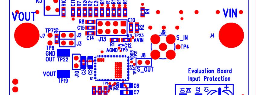
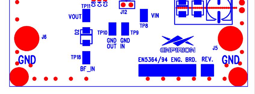
7 Figure 5 : Evaluation Board Layout. Page 7 of 0
8 Test Recommendations To guarantee measurement accuracy, the following precautions should be observed:. Make all input and output voltage measurements at the board using the test points provided. This will eliminate voltage drop across the line and load cables that can produce false readings. 2. Measure input and output current with series ammeters or accurate shunt resistors. This is especially important when measuring efficiency. 3. Use a low-loop-inductance probe shown here to measure switching signals to avoid noise coupling into the probe ground lead. J0 is a convenient point to measure output ripple and load transient deviation. Please refer to Enpirion s Output Ripple Measurement application note for more accurate ripple measurements. Figure 6 : Low-loop-inductance Oscilloscope Probe 4. The board includes a 0k pull-up for the POK signal and ready to monitor the power OK status. 5. A 5nF soft-start capacitor is populated on the board for ~msec softstart time. 6. Please consult Enpirion Applications Support if you are planning to perform any special EMI or noise measurements on this evaluation board. Input and Output Capacitors The input capacitance requirement is between 20-40uF for the EN5364QI and 30-40uF for the EN5394QI. The voltage rating should be high enough to provide adequate margin for your application. This evaluation board is populated with 2x22uF, 206, X5R capacitors. The output capacitance requirement is approximately 50uF at the voltage sensing point for the EN5364QI and approximately 00uF for the EN5394QI. The board is populated with a 47uF, 206, X5R and a 0uF,, X7R capacitor for the EN5364QI and 2 x 47uF, 206, X5R capacitor for the EN5394QI evaluation board. NOTE: Capacitors must be X5R or X7R dielectric formulations to ensure adequate capacitance over operating voltage and temperature ranges. Page 8 of 0
9 MAR2 MAR ENA EN_PB M/S VFB MAR2 MAR TP2 TP3 R R2 TP7 SS S_DEL R7 R20 R2 C TP5 EAOUT C2 TP4 TP5 TP6 R9 TP3 M/S EN_PB ENA R4 POK TP23 AVIN C0 VSENSE R R2 GND OUT J0 2 TP7 TP22 TP9 R6 206/ C3 206 TP6 C NC4 NC5 68 NC6 67 NC7 66 NC8 65 NC9 64 VSENSE 63 NC20 U EN5364QI / EN5394QI NC2 MAR2 62 NC22 MAR 6 S_DELAY 60 NC23 NC24 SS 59 OCP_ADJ 58 NC(SW) NC(SW) EAOUT 57 VFB POK 54 AVIN 53 ENABLE 52 EN_PB 5 M/S 50 S_IN 49 S_OUT 48 PVIN NC47 47 NC46 46 NC45 45 NC44 44 PVIN 43 PVIN 42 PVIN 4 PVIN 40 PVIN 39 PVIN 38 PVIN 37 PVIN 36 PVIN 35 AVIN TP2 TP20 TP4 J4 R3 J9 2 J8 S_OUT J2 2 J3 TP J C8 C4 C5 SW TP2 TP C6 TP0 GND OUT TP9 GND IN C TP8 PVIN VIN D2 J5 J6 2 J2 TP8 BF_IN Eval Board Input Protection PVIN U2 D + C S2A Sync Delay Programming S_DEL Top turn pot R5 AVIN FB C3 MAR2 MAR ENA EN_PB M/S J MAR2 MAR ENA EN_PB M/S Additional Compensation Components VFB Programming VSENSE C20 R J3 R0 C5 R3 R4 R6 R8 VFB R8 C4 EAOUT Figure 7 : Evaluation Board Schematic Page 9 of 0
10 Contact Information Enpirion, Inc. Perryville III 53 Frontage Road, Suite 20 Hampton, NJ Phone: Fax: Enpirion reserves the right to make changes in circuit design and/or specifications at any time without notice. Information furnished by Enpirion is believed to be accurate and reliable. Enpirion assumes no responsibility for its use or for infringement of patents or other third party rights, which may result from its use. Enpirion products are not authorized for use in nuclear control systems, as critical components in life support systems or equipment used in hazardous environment without the express written authority from Enpirion. Page 0 of 0
Enpirion EN6360QI 8A DC/DC Converter w/integrated Inductor Evaluation Board
 January 0 Enpirion EN660QI 8 DC/DC Converter w/integrated Inductor Evaluation Board Introduction Thank you for choosing Enpirion, the source for Ultra small foot print power converter products! The EN660QI
Enpirion EP5357xUI DC/DC Converter Module Evaluation Board
 Enpirion EP5357xUI DC/DC Converter Module Evaluation Board Introduction Thank you for choosing Altera Enpirion power products! This application note describes how to test the EP5357xUI (EP5357LUI, EP5357HUI)
EN5364QI-E. Preliminary. Feature Rich 6A Voltage Mode Synchronous Buck PWM DC-DC Converter with Integrated Inductor RoHS Compliant - Halogen Free
 Feature Rich 6A Voltage Mode Synchronous Buck PWM DC-DC Converter with Integrated Inductor RoHS Compliant - Halogen Free Description The is a Power Supply on a Chip (PwrSoC) DC to DC converter in a 68
EP5388QI 800mA Synchronous Buck Regulator With Integrated Inductor 3mm x 3mm x 1.1mm Package
 800mA Synchronous Buck Regulator With Integrated Inductor 3mm x 3mm x 1.1mm Package Product Overview The is a synchronous buck converter with integrated Inductor, PWM controller, MOSFETS, and Compensation
EN A Voltage Mode Synchronous Buck PWM DC-DC Converter with Integrated Inductor RoHS Compliant July Features. Description.
 EN5330 3A Voltage Mode Synchronous Buck PWM DC-DC Converter with Integrated Inductor RoHS Compliant July 2007 Description The EN5330 is a Power System on a Chip DC- DC converter. It is specifically designed
EP5357LUI/EP5357HUI 600mA Synchronous Buck Regulator with Integrated Inductor RoHS Compliant; Halogen Free
 600mA Synchronous Buck Regulator with Integrated Inductor RoHS Compliant; Halogen Free Description The EP5357xUI (x = L or H) is a 600mA PowerSOC. The EP5357xUI integrates MOSFET switches, control, compensation,
EN5336QI-E. 3A Voltage Mode Synchronous Buck PWM DC-DC Converter with Integrated Inductor External Feedback Output Voltage Programming
 3A Voltage Mode Synchronous Buck PWM DC-DC Converter with Integrated Inductor External Feedback Output Voltage Programming Description The is a Power System on Silicon DC- DC converter. It is specifically
Enpirion Power Datasheet EV1380QI 8A PowerSoC Highly Integrated Synchronous DC-DC DDR2/3/4/QDR TM Memory Termination
 Enpirion Power Datasheet EV1380QI 8A PowerSoC Highly Integrated Synchronous DC-DC DDR2/3/4/QDR TM Memory Termination Description The EV1380QI is a Power System on a Chip (PowerSoC) DC to DC converter in
Enpirion Power Datasheet EN5364QI 6A PowerSoC Voltage Mode Synchronous Buck PWM DC-DC Converter With Integrated Inductor
 Enpirion Power Datasheet 6A PowerSoC Voltage Mode Synchronous Buck PWM DC-DC Converter With Integrated Inductor Description Typical Application Circuit The is a Power Supply on a Chip (PwrSoC) DC to DC
EN5322QI-E. 2 A Voltage Mode Synchronous Buck PWM DC-DC Converter with Integrated Inductor. Features. General Description.
 Created on 3/12/2008 2:55:00 PM 2 A Voltage Mode Synchronous Buck PWM DC-DC Converter with Integrated Inductor March 2008 RoHS Compliant Halogen Free General Description The EN5322 is a high efficiency
Evaluation Board for ADP2118 EVAL-ADP2118
 Evaluation Board for ADP8 EVAL-ADP8 GENERAL DESCRIPTION The evaluation (demo) board provides an easy way to evaluate the ADP8 buck regulator. This data sheet describes how to quickly set up the board to
Enpirion Power Datasheet EN6360QA 8A PowerSoC Highly Integrated Synchronous DC-DC Buck with Integrated Inductor
 Enpirion Power Datasheet 8A PowerSoC Highly Integrated Synchronous DC-DC Buck with Integrated Inductor Description The is an 8A Power System on a Chip (PowerSoC) DC to DC converter with an integrated inductor,
1MHz, 3A Synchronous Step-Down Switching Voltage Regulator
 FEATURES Guaranteed 3A Output Current Efficiency up to 94% Efficiency up to 80% at Light Load (10mA) Operate from 2.8V to 5.5V Supply Adjustable Output from 0.8V to VIN*0.9 Internal Soft-Start Short-Circuit
HM2259D. 2A, 4.5V-20V Input,1MHz Synchronous Step-Down Converter. General Description. Features. Applications. Package. Typical Application Circuit
 HM2259D 2A, 4.5V-20V Input,1MHz Synchronous Step-Down Converter General Description Features HM2259D is a fully integrated, high efficiency 2A synchronous rectified step-down converter. The HM2259D operates
EN6363QI 6A PowerSoC. Evaluation board user guide enpirion power solutions. Step-Down DC-DC Switching Converter with Integrated Inductor
 Evaluation board user guide enpirion power solutions EN6363QI 6A PowerSoC Step-Down DC-DC Switching Converter with Integrated Inductor EVALUATION BOARD OVERVIEW 1 2 3 8 4 7 9 5 6 Figure 1: Evaluation Board
EN63A0QA 12A PowerSoC
 DataSheeT enpirion power solutions EN63A0QA 12A PowerSoC Step-Down DC-DC Switching Converter with Integrated Inductor DESCRIPTION The EN63A0QA is an Intel Enpirion Power System on a Chip (PowerSoC) DC-DC
CEP8101A Rev 1.0, Apr, 2014
 Wide-Input Sensorless CC/CV Step-Down DC/DC Converter FEATURES 42V Input Voltage Surge 40V Steady State Operation Up to 2.1A output current Output Voltage 2.5V to 10V Resistor Programmable Current Limit
Enpirion Power Datasheet EP5348UI 400mA PowerSoC Synchronous Buck Regulator With Integrated Inductor
 Enpirion Power Datasheet 400mA PowerSoC Synchronous Buck Regulator With Integrated Inductor Description The delivers the optimal trade-off between footprint and efficiency. It is a perfect alternative
EN63A0QI 12A PowerSoC
 DataSheeT enpirion power solutions EN63A0QI 12A PowerSoC Step-Down DC-DC Switching Converter with Integrated Inductor DESCRIPTION The EN63A0QI is an Intel Enpirion Power System on a Chip (PowerSoC) DC-DC
Features V OUT. Part Number. *Optimized PCB Layout file downloadable from to assure first pass design success.
 Enpirion Power Datasheet 6A PowerSoC Voltage Mode Synchronous Buck PWM DC-DC Converter with Integrated Inductor External Output Voltage Programming Description This Altera Enpirion solution is a Power
CEP8113A Rev 2.0, Apr, 2014
 Wide-Input Sensorless CC/CV Step-Down DC/DC Converter FEATURES 42V Input Voltage Surge 40V Steady State Operation Up to 3.5A output current Output Voltage 2.5V to 10V Resistor Programmable Current Limit
PAM2421 EVB User Guide
 EV Board User Guide AE Department 1. Revision Information PAM2421 Date Revision Description Comment 2011/09 V1.0 Initial Release 2. PAM2804 General Description The PAM2421 devices are high-performance,
HM V 2A 500KHz Synchronous Step-Down Regulator
 Features HM8114 Wide 4V to 30V Operating Input Range 2A Continuous Output Current Fixed 500KHz Switching Frequency No Schottky Diode Required Short Protection with Hiccup-Mode Built-in Over Current Limit
ACT111A. 4.8V to 30V Input, 1.5A LED Driver with Dimming Control GENERAL DESCRIPTION FEATURES APPLICATIONS TYPICAL APPLICATION CIRCUIT
 4.8V to 30V Input, 1.5A LED Driver with Dimming Control FEATURES Up to 92% Efficiency Wide 4.8V to 30V Input Voltage Range 100mV Low Feedback Voltage 1.5A High Output Capacity PWM Dimming 10kHz Maximum
Enpirion Power Datasheet EN63A0QA 12A PowerSoC Highly Integrated Synchronous Buck With Integrated Inductor
 EFFICIEY (%) Enpirion Power Datasheet 12A PowerSoC Highly Integrated Synchronous Buck With Integrated Inductor Description The is a 12A Power System on a Chip (PowerSoC) DC to DC converter with an integrated
Enpirion Power Datasheet EN5322QI 2A PowerSoC Synchronous Buck DC-DC Converter with Integrated Inductor
 Enpirion Power Datasheet EN5322QI 2A PowerSoC Synchronous Buck DC-DC Converter with Integrated Inductor General Description The EN5322 is a high efficiency synchronous buck converter with integrated inductor,
MP2313 High Efficiency 1A, 24V, 2MHz Synchronous Step Down Converter
 The Future of Analog IC Technology MP2313 High Efficiency 1A, 24V, 2MHz Synchronous Step Down Converter DESCRIPTION The MP2313 is a high frequency synchronous rectified step-down switch mode converter
UM mA, 600kHz Step-Up DC-DC Converter UM3433 SOT23-6. General Description. Rev.05 Dec /9
 General Description UM3433 600mA, 600kHz Step-Up DC-DC Converter UM3433 SOT23-6 The UM3433 is synchronous rectified, fixed frequency, step-up DC/DC converter series delivering high efficiency in a low
FEATURES DESCRIPTION APPLICATIONS PACKAGE REFERENCE
 DESCRIPTION The is a monolithic synchronous buck regulator. The device integrates 100mΩ MOSFETS that provide 2A continuous load current over a wide operating input voltage of 4.75V to 25V. Current mode
Enpirion Power Datasheet EP5388QI 800mA PowerSoC Synchronous Buck Regulator With Integrated Inductor
 Enpirion Power Datasheet 800mA PowerSoC Synchronous Buck Regulator With Integrated Inductor Product Overview The is a synchronous buck converter with integrated Inductor, PWM controller, MOSFETS, and Compensation
1.5 MHz, 600mA Synchronous Step-Down Converter
 GENERAL DESCRIPTION is a 1.5Mhz constant frequency, slope compensated current mode PWM step-down converter. The device integrates a main switch and a synchronous rectifier for high efficiency without an
4.5V to 32V Input High Current LED Driver IC For Buck or Buck-Boost Topology CN5816. Features: SHDN COMP OVP CSP CSN
 4.5V to 32V Input High Current LED Driver IC For Buck or Buck-Boost Topology CN5816 General Description: The CN5816 is a current mode fixed-frequency PWM controller for high current LED applications. The
HM V 3A 500KHz Synchronous Step-Down Regulator
 Features Wide 4V to 18V Operating Input Range 3A Continuous Output Current 500KHz Switching Frequency Short Protection with Hiccup-Mode Built-in Over Current Limit Built-in Over Voltage Protection Internal
Enpirion Power Datasheet EP53A8LQA/HQA 1A PowerSoC Voltage Mode Synchronous PWM Buck with Integrated Inductor
 Enpirion Power Datasheet EP53A8LQA/HQA 1A PowerSoC Voltage Mode Synchronous PWM Buck with Integrated Inductor Description The EP53A8LQA and EP53A8HQA are 1A PowerSoCs that are AEC-Q100 qualified for automotive
1MHz, 3A Synchronous Step-Down Switching Voltage Regulator
 FEATURES Guaranteed 3A Output Current Efficiency up to 95% Operate from 2.8V to 5.5V Supply Adjustable Output from 0.8V to VIN*0.86 Internal Soft-Start Short-Circuit and Thermal -Overload Protection 1MHz
1.5MHz, 1.5A Step-Down Converter
 1.5MHz, 1.5A Step-Down Converter General Description The is a 1.5MHz constant frequency current mode PWM step-down converter. It is ideal for portable equipment which requires very high current up to 1.5A
Features. R1 10k. 10nF. R2 3.83k
 High Efficiency 1MHz Synchronous Buck Regulator General Description The Micrel is a high efficiency 1MHz PWM synchronous buck switching regulator. The features low noise constant frequency PWM operation
DESCRIPTION FEATURES APPLICATIONS TYPICAL APPLICATION. 500KHz, 18V, 2A Synchronous Step-Down Converter
 DESCRIPTION The is a fully integrated, high-efficiency 2A synchronous rectified step-down converter. The operates at high efficiency over a wide output current load range. This device offers two operation
AT V Synchronous Buck Converter
 38V Synchronous Buck Converter FEATURES DESCRIPTION Wide 8V to 38V Operating Input Range Integrated two 140mΩ Power MOSFET Switches Feedback Voltage : 220mV Internal Soft-Start / VFB Over Voltage Protection
A7121A. AiT Semiconductor Inc. APPLICATION ORDERING INFORMATION TYPICAL APPLICATION
 DESCRIPTION The is a high efficiency monolithic synchronous buck regulator using a constant frequency, current mode architecture. Supply current with no load is 300uA and drops to
MIC33153 Evaluation Board
 4MHz 1.2A PWM Buck Regulator with HyperLight Load and Power Good General Description This board enables the evaluation of the MIC33153, a fully integrated 1.2A, 4MHz switching regulator featuring HyperLight
AT V,3A Synchronous Buck Converter
 FEATURES DESCRIPTION Wide 8V to 40V Operating Input Range Integrated 140mΩ Power MOSFET Switches Output Adjustable from 1V to 25V Up to 93% Efficiency Internal Soft-Start Stable with Low ESR Ceramic Output
idesyn id8802 2A, 23V, Synchronous Step-Down DC/DC
 2A, 23V, Synchronous Step-Down DC/DC General Description Applications The id8802 is a 340kHz fixed frequency PWM synchronous step-down regulator. The id8802 is operated from 4.5V to 23V, the generated
Enpirion Power Datasheet EC2630QI 4.5A, 27W 12V DC-DC Intermediate Voltage Bus Converter
 Enpirion Power Datasheet EC2630QI 4.5A, 27W 12V DC-DC Intermediate Voltage Bus Converter Description Altera s Enpirion EC2630QI is a high density DC-DC Intermediate Voltage Bus Converter which generates
MP V to 5.5V Input, 1.2MHz, Dual-ch LCD Bias Power Supply
 MP5610 2.7V to 5.5V Input, 1.2MHz, Dual-ch LCD Bias Power Supply DESCRIPTION The MP5610 is a dual-output converter with 2.7V-to-5.5V input for small size LCD panel bias supply. It uses peak-current mode
User s Manual. ACPL-339J Isolated Gate Driver Evaluation Board. Quick-Start. Testing Either Arm of The Half Bridge Inverter Driver (without IGBT)
") ACPL-339J Isolated Gate Driver Evaluation Board User s Manual Quick-Start Visual inspection is needed to ensure that the evaluation board is received in good condition. The default connections of the evaluation
ACPL-339J Isolated Gate Driver Evaluation Board User s Manual Quick-Start Visual inspection is needed to ensure that the evaluation board is received in good condition. The default connections of the evaluation
Engineer-to-Engineer Note
 Engineer-to-Engineer Note EE-339 a Technical notes on using Analog Devices DSPs, processors and development tools Visit our Web resources http://www.analog.com/ee-notes and http://www.analog.com/processors
MPM V-5.5V, 4A, Power Module, Synchronous Step-Down Converter with Integrated Inductor
 The Future of Analog IC Technology MPM3840 2.8V-5.5V, 4A, Power Module, Synchronous Step-Down Converter with Integrated Inductor DESCRIPTION The MPM3840 is a DC/DC module that includes a monolithic, step-down,
Purpose. Table of Contents. Purpose Introduction General Product Information Key Performance Summary Table... 3
 Purpose The RT8295A is a high-efficiency current mode synchronous step-down regulator that can deliver up to 2A output current from a wide input voltage range of 4.5V to 23V. This document explains the
The ASD5001 is available in SOT23-5 package, and it is rated for -40 to +85 C temperature range.
 General Description The ASD5001 is a high efficiency, step up PWM regulator with an integrated 1A power transistor. It is designed to operate with an input Voltage range of 1.8 to 15V. Designed for optimum
ACE726C. 500KHz, 18V, 2A Synchronous Step-Down Converter. Description. Features. Application
 Description The is a fully integrated, high-efficiency 2A synchronous rectified step-down converter. The operates at high efficiency over a wide output current load range. This device offers two operation
Enpirion Power Datasheet EP53A7LQI/EP53A7HQI 1A PowerSoC Light Load Mode Buck Regulator with Integrated Inductor
 Enpirion Power Datasheet EP53A7LQI/EP53A7HQI 1A PowerSoC Light Load Mode Buck Regulator with Integrated Inductor Description The EP53A7xQI (x = L or H) is a 1000mA PowerSOC. The EP53A7xQI integrates MOSFET
A7115. AiT Semiconductor Inc. APPLICATION ORDERING INFORMATION TYPICAL APPLICATION
 DESCRIPTION The is a high efficiency monolithic synchronous buck regulator using a constant frequency, current mode architecture. Supply current with no load is 300uA and drops to
SR A, 30V, 420KHz Step-Down Converter DESCRIPTION FEATURES APPLICATIONS TYPICAL APPLICATION
 SR2026 5A, 30V, 420KHz Step-Down Converter DESCRIPTION The SR2026 is a monolithic step-down switch mode converter with a built in internal power MOSFET. It achieves 5A continuous output current over a
600mA, 1.2MHz, Synchronous Step-Down DC-DC Converter UM3501 SOT23-5 UM3501DA DFN Features. Efficiency (%) C3 10uF
 C3 10uF") 600mA, 1.2MHz, Synchronous Step-Down DC-DC Converter UM3501 SOT23-5 UM3501DA DFN6 2.0 2.0 General Description UM3501 is a high-efficiency pulse-width-modulated (PWM) step-down DC-DC converter, capable
600mA, 1.2MHz, Synchronous Step-Down DC-DC Converter UM3501 SOT23-5 UM3501DA DFN6 2.0 2.0 General Description UM3501 is a high-efficiency pulse-width-modulated (PWM) step-down DC-DC converter, capable
Evaluation Board for Step-Down DC-to-DC Converter Solution EVAL-ADP2107
 Evaluation Board for Step-Down DC-to-DC Converter Solution FEATURES Efficiency > 95% Input voltage range: 2.7 V to 5.5 V Output voltage range: 0.8 V to VIN Maximum output current: 2.0 A Switching frequency:.2
MP1482 2A, 18V Synchronous Rectified Step-Down Converter
 The Future of Analog IC Technology MY MP48 A, 8 Synchronous Rectified Step-Down Converter DESCRIPTION The MP48 is a monolithic synchronous buck regulator. The device integrates two 30mΩ MOSFETs, and provides
AUR MHz, 1A, Step-Down DC-DC Converter. Features. Description. Applications. Package Information. Order Information
 1.5MHz, 1A, Step-Down DC-DC Converter Features High efficiency Buck Power Converter Low Quiescent Current 1A Output Current Adjustable Output Voltage from 1V to 3.3V Wide Operating Voltage Ranges : 2.5
Features. Applications. 1.2MHz Boost Converter with OVP in Thin SOT-23-6
 1.2MHz PWM Boost Converter with OVP General Description The is a 1.2MHz pulse width modulated (PWM) step-up switching regulator that is optimized for low power, high output voltage applications. With a
QUICK START GUIDE FOR DEMONSTRATION CIRCUIT 968A-D ISOLATED DC/DC POWER CONVERTER LT1952 DESCRIPTION
 QUICK START GUIDE FOR DEMONSTRATION CIRCUIT 98A-D LT9 DESCRIPTION Demonstration circuit 98A-D is isolated input to high current output /8th Brick footprint converter featuring the LT 9 switching controller.
MP2131 High Efficiency, 4 A, 5.5 V, 1.2 MHz Synchronous Step-Down Converter
 The Future of Analog IC Technology MP2131 High Efficiency, 4 A, 5.5 V, 1.2 MHz Synchronous Step-Down Converter DESCRIPTION The MP2131 is a monolithic step-down, switchmode converter with built-in internal
Features MIC2193BM. Si9803 ( 2) 6.3V ( 2) VDD OUTP COMP OUTN. Si9804 ( 2) Adjustable Output Synchronous Buck Converter
 6.3V ( 2) VDD OUTP COMP OUTN. Si9804 ( 2) Adjustable Output Synchronous Buck Converter") MIC2193 4kHz SO-8 Synchronous Buck Control IC General Description s MIC2193 is a high efficiency, PWM synchronous buck control IC housed in the SO-8 package. Its 2.9V to 14V input voltage range allows
MIC2193 4kHz SO-8 Synchronous Buck Control IC General Description s MIC2193 is a high efficiency, PWM synchronous buck control IC housed in the SO-8 package. Its 2.9V to 14V input voltage range allows
Boundary Mode Offline LED Driver Using MP4000. Application Note
 The Future of Analog IC Technology AN046 Boundary Mode Offline LED Driver Using MP4000 Boundary Mode Offline LED Driver Using MP4000 Application Note Prepared by Zheng Luo March 25, 2011 AN046 Rev. 1.0
Enpirion Power Datasheet EN5329QI 2A PowerSoC Low Profile Synchronous Buck DC-DC Converter with Integrated Inductor
 Enpirion Power Datasheet EN5329QI 2A PowerSoC Low Profile Synchronous Buck DC-DC Converter with Integrated Inductor Description The EN5329QI is a highly integrated, low profile, highly efficient, 2A synchronous
AIC2858 F. 3A 23V Synchronous Step-Down Converter
 3A 23V Synchronous Step-Down Converter FEATURES 3A Continuous Output Current Programmable Soft Start 00mΩ Internal Power MOSFET Switches Stable with Low ESR Output Ceramic Capacitors Up to 95% Efficiency
EN6340QI 4A PowerSoC. DataSheeT enpirion power solutions. Step-Down DC-DC Switching Converter with Integrated Inductor DESCRIPTION FEATURES
 DataSheeT enpirion power solutions EN6340QI 4A PowerSoC Step-Down DC-DC Switching Converter with Integrated Inductor DESCRIPTION The EN6340QI is an Intel Enpirion Power System on a Chip (PowerSoC) DC-DC
Evaluates: MAX V 16V, Dual 3A Synchronous Buck Converter. MAX17509 Evaluation Kit. General Description. Quick Start.
 General Description The MAX7509 evaluation kit (EV kit) is a fully assembled and tested circuit board to demonstrate the performance of the MAX7509, a dual 3A, high-efficiency, synchronous step-down DC-DC
TFT-LCD DC/DC Converter with Integrated Backlight LED Driver
 TFT-LCD DC/DC Converter with Integrated Backlight LED Driver Description The is a step-up current mode PWM DC/DC converter (Ch-1) built in an internal 1.6A, 0.25Ω power N-channel MOSFET and integrated
Features. RAMP Feed Forward Ramp/ Volt Sec Clamp Reference & Isolation. Voltage-Mode Half-Bridge Converter CIrcuit
 MIC3838/3839 Flexible Push-Pull PWM Controller General Description The MIC3838 and MIC3839 are a family of complementary output push-pull PWM control ICs that feature high speed and low power consumption.
Enpirion Power Datasheet EN5319QI 1.5A PowerSoC Low Profile Synchronous Buck DC-DC Converter with Integrated Inductor
 Enpirion Power Datasheet EN5319QI 1.5A PowerSoC Low Profile Synchronous Buck DC-DC Converter with Integrated Inductor Description The EN5319QI is a highly integrated, low profile, highly efficient, 1.5A
MP2497-A 3A, 50V, 100kHz Step-Down Converter with Programmable Output OVP Threshold
 The Future of Analog IC Technology MP2497-A 3A, 50V, 100kHz Step-Down Converter with Programmable Output OVP Threshold DESCRIPTION The MP2497-A is a monolithic step-down switch mode converter with a programmable
A7221A DC-DC CONVERTER/BUCK (STEP-DOWN) 600KHz, 16V, 2A SYNCHRONOUS STEP-DOWN CONVERTER
 600KHz, 16V, 2A SYNCHRONOUS STEP-DOWN CONVERTER") DESCRIPTION The is a fully integrated, high efficiency 2A synchronous rectified step-down converter. The operates at high efficiency over a wide output current load range. This device offers two operation
DESCRIPTION The is a fully integrated, high efficiency 2A synchronous rectified step-down converter. The operates at high efficiency over a wide output current load range. This device offers two operation
1A Buck/Boost Charge Pump LED Driver
 1A Buck/Boost Charge Pump LED Driver Description The Buck/Boost charge pump LED driver is designed for powering high brightness white LEDs for camera flash applications. The automatically switches modes
MP2314 High Efficiency 2A, 24V, 500kHz Synchronous Step Down Converter
 The Future of Analog IC Technology MP2314 High Efficiency 2A, 24V, 500kHz Synchronous Step Down Converter DESCRIPTION The MP2314 is a high frequency synchronous rectified step-down switch mode converter
LM3102 Demonstration Board Reference Design
 LM3102 Demonstration Board Reference Design Introduction The LM3102 Step Down Switching Regulator features all required functions to implement a cost effective, efficient buck power converter capable of
SGM6232 2A, 38V, 1.4MHz Step-Down Converter
 GENERAL DESCRIPTION The is a current-mode step-down regulator with an internal power MOSFET. This device achieves 2A continuous output current over a wide input supply range from 4.5V to 38V with excellent
ACT A CC/CV Step-Down DC/DC Converter FEATURES APPLICATIONS GENERAL DESCRIPTION. Rev 2, 14-Nov-12
 1.25A CC/CV Step-Down DC/DC Converter FEATURES 10V-30V Input Voltage 40V Transparent Input Voltage Surge Up to 1.25A Constant Output Current Output Voltage up to 12V Good EMC Performance on Single Layer
ACT8310/ A, PWM Step-Down DC/DCs in TDFN GENERAL DESCRIPTION FEATURES APPLICATIONS SYSTEM BLOCK DIAGRAM ACT8311. Rev 4, 08-Feb-2017
 1.5A, PWM Step-Down DC/DCs in TDFN FEATURES Multiple Patents Pending Up to 95% High Efficiency Up to 1.5A Guaranteed Output Current (ACT8311) 1.35MHz Constant Frequency Operation Internal Synchronous Rectifier
MIC2238. General Description. Features. Applications. Typical Application. 2.5MHz Dual Phase PWM Buck Regulator
 2.5MHz Dual Phase PWM Buck Regulator General Description The Micrel is dual output 2-phase synchronous buck (step down) PWM DC/DC switching regulator. Power conversion efficiencies of above 95% are easily
AP3403. General Description. Features. Applications. Typical Application Schematic. A Product Line of Diodes Incorporated
 General Description APPLICATION NOTE 1123 600mA STEP-DOWN DC/DC CONVERTER WITH SYNCHRONOUS RECTIFIER The is a 2.0MHz fixed frequency, current mode, PWM synchronous buck (step-down) DC-DC converter, capable
eorex EP MHz, 600mA Synchronous Step-down Converter
 1.5MHz, 600mA Synchronous Step-down Converter Features High Efficiency: Up to 96% 1.5MHz Constant Switching Frequency 600mA Output Current at V IN = 3V Integrated Main Switch and Synchronous Rectifier
Evaluation Board for ADP2114 EVAL-ADP2114
 Evaluation Board for ADP EVAL-ADP FEATURES Full-featured demo board for the ADP Standalone capability Configurable dual synchronous step-down, dc-to-dc switching regulator Dual A/ A or A/ A output or single
Designing High Power Parallel Arrays with PRMs
 APPLICATION NOTE AN:032 Designing High Power Parallel Arrays with PRMs Ankur Patel Applications Engineer August 2015 Contents Page Introduction 1 Arrays for Adaptive Loop / Master-Slave Operation 1 High
RT8086B. 3.5A, 1.2MHz, Synchronous Step-Down Converter. General Description. Features. Ordering Information RT8086B. Applications. Marking Information
 RT8086B 3.5A, 1.2MHz, Synchronous Step-Down Converter General Description The RT8086B is a high efficiency, synchronous step-down DC/DC converter. The available input voltage range is from 2.8V to 5.5V
CE8313 Series. High Efficiency 1.25MHz, 2.5A Boost Regulator APPLICATIONS:
 INTRODUCTION: The CE8313 is a high efficiency boost switching regulator especially designed for single cell lithium battery powered applications. It generates an output voltage of up to 5.5V from an input
A7108. AiT Semiconductor Inc. APPLICATION ORDERING INFORMATION TYPICAL APPLICATION
 DESCRIPTION The is a high efficiency monolithic synchronous buck regulator using a constant frequency, current mode architecture. The device is available in an adjustable version. Supply current with no
Analog Technologies. ATI2202 Step-Down DC/DC Converter ATI2202. Fixed Frequency: 340 khz
 Step-Down DC/DC Converter Fixed Frequency: 340 khz APPLICATIONS LED Drive Low Noise Voltage Source/ Current Source Distributed Power Systems Networking Systems FPGA, DSP, ASIC Power Supplies Notebook Computers
Thermally enhanced Low V FB Step-Down LED Driver ADT6780
 Thermally enhanced Low V FB Step-Down LED Driver General Description The is a thermally enhanced current mode step down LED driver. That is designed to deliver constant current to high power LEDs. The
TS mA / 1.5MHz Synchronous Buck Converter
 SOT-25 Pin Definition: 1. EN 2. Ground 3. Switching Output 4. Input 5. Feedback General Description The TS3406 is a high efficiency monolithic synchronous buck regulator using a 1.5MHz constant frequency,
23V 3A Step-Down DC/DC Converter
 23V 3A Step-Down DC/DC Converter FEATURES 3A Continuous Output Current Programmable Soft Start 100mΩ Internal Power MOSFET Switch Stable with Low ESR Output Ceramic Capacitors Up to 95% Efficiency 22µA
FAN2013 2A Low-Voltage, Current-Mode Synchronous PWM Buck Regulator
 FAN2013 2A Low-Voltage, Current-Mode Synchronous PWM Buck Regulator Features 95% Efficiency, Synchronous Operation Adjustable Output Voltage from 0.8V to V IN-1 4.5V to 5.5V Input Voltage Range Up to 2A
SGM6132 3A, 28.5V, 1.4MHz Step-Down Converter
 GENERAL DESCRIPTION The SGM6132 is a current-mode step-down regulator with an internal power MOSFET. This device achieves 3A continuous output current over a wide input supply range from 4.5V to 28.5V
MIC2245. Features. General Description. Applications. Typical Application. 4MHz PWM Synchronous Buck Regulator with LDO Standby Mode
 4MHz PWM Synchronous Buck Regulator with LDO Standby Mode General Description The Micrel is a high efficiency 4MHz pulse width modulated (PWM) synchronous buck (stepdown) regulator that features a LOWQ
Wide-Input Sensorless CC/CV Step-Down DC/DC Converter
 Wide-Input Sensorless CC/CV Step-Down DC/DC Converter FEATURES Up to 40V Input Voltage Up to 1.5A Constant Output Current Output Voltage up to 12V Patent Pending ActiveCC Constant Current Control Integrated
MIC4414/4415. General Description. Features. Applications. Typical Application. 1.5A, 4.5V to 18V, Low-Side MOSFET Driver
 MIC4414/4415 1.5A, 4.5V to 18V, Low-Side MOSFET Driver General Description The MIC4414 and MIC4415 are low-side MOSFET drivers designed to switch an N-channel enhancement type MOSFET in low-side switch
Enpirion Power Datasheet EP5368QI 600mA PowerSoC Synchronous Buck Regulator With Integrated Inductor
 Enpirion Power Datasheet 600mA PowerSoC Synchronous Buck Regulator With Integrated Inductor Description The is a synchronous buck converter with integrated Inductor, PWM controller, MOSFETS, and Compensation
Enpirion Power Datasheet EN5329QI 2A PowerSoC Low Profile Synchronous Buck DC-DC Converter with Integrated Inductor
 Enpirion Power Datasheet EN5329QI 2A PowerSoC Low Profile Synchronous Buck DC-DC Converter with Integrated Inductor Description The EN5329QI is a highly integrated, low profile, highly efficient, 2A synchronous
EUP2511. HQI Boost Converter With 2.1A Switch In Tiny SOT-23 Package FEATURES DESCRIPTION APPLICATIONS. Typical Application Circuit
 HQI Boost Converter With 2.1A Switch In Tiny SOT-23 Package DESCRIPTION The is a high performance current mode, PWM step-up converter. With an internal 2.1A, 150mΩ MOSFET, it can generate 5 at up to 900mA
AIC mA, 1.2MHz Synchronous Step-Up Converter
 700mA, 1.2MHz Synchronous Step-Up Converter FEATURES V IN Start Up Voltage: 0.9V Output Voltage Range: from 2.7V to 5.25V. Up to 94% Efficiency 1.2MHz Fixed Frequency Switching Built-in current mode compensation
Features MIC2194BM VIN EN/ UVLO CS OUTP VDD FB. 2k COMP GND. Adjustable Output Buck Converter MIC2194BM UVLO
 MIC2194 400kHz SO-8 Buck Control IC General Description s MIC2194 is a high efficiency PWM buck control IC housed in the SO-8 package. Its 2.9V to 14V input voltage range allows it to efficiently step