INSTRUCTION MANUAL FOR THE Premier Combo Plus DIGITAL TENS/EMS
|
|
|
- Linda Newman
- 5 years ago
- Views:
Transcription


1 INSTRUCTION MANUAL FOR THE Premier Combo Plus DIGITAL TENS/EMS Distributed by: V1.0 Model No.: EM-6300A Read Before Use 0434
2 Chapter INDEX Contents 1. General Description Introduction Cautions Warnings Contraindications Adverse Reactions Construction Technical Specifications Replacement Parts Accessories Graphic Symbols Operating Instructions Parameter Controls Attachment of Electrode Lead Wires Lead Wire Maintenance Electrode Options Electrode Placement Tips for Skin Care Application of Reusable self adhesive electrodes Adjusting the Controls Battery Information Maintenance, Transportation, and Storage Safety-Technical Controls Malfunctions Conformity to Safety Standards Warranty...36 Manufacturer...36 Representative in the EU Electromagnetic Compatibilityinformation Appendix
3 Chapter 1: GENERAL DESCRIPTION The Premier Combo Plus TENS/EMS is a fully digital battery operated pulse generator that sends electrical impulses to the nerves and underlying muscle groups. This unit is a combination stimulator of TENS and EMS which can be used for pain relief and muscle stimulation. The device is provided with two controllable output channels, each independent of the other. A pair of electrodes can be connected to each output channel. The intensity level and settings are controlled by press buttons EXPLANATION OF PAIN Chapter 2 : INTRODUCTION Pain is a warning system and the body s method of telling us that something is wrong. Pain is important; without it abnormal conditions may go undetected, causing damage or injury to vital parts of our bodies. Even though pain is a necessary warning signal of trauma or malfunction in the body, nature may have gone too far in its design. Aside from its value in diagnosis, long-lasting persistent pain serves no useful purpose. Pain does not begin until coded messages travel to the brain where they are decoded, analyzed, and reacted to. The pain message travels from the injured area along the small nerves leading to the spinal cord. Here the message is switched to different nerves that travel up the spinal cord to the brain. The pain message is interpreted and pain is perceived. EXPLANATION OF TENS Transcutaneous Electrical Nerve Stimulation is a non-invasive, drugfree method of controlling pain. TENS uses tiny electrical impulses sent through the skin to nerves to modify your pain perception. TENS does not cure any physiological problem; it only helps control the pain. TENS does not work for everyone; however, in most patients it is effective in reducing or eliminating the pain, allowing for a return to normal activity. 2 HOW TENS WORKS There is nothing magic about Transcutaneous Electrical Nerve Stimulation (TENS). TENS is intended to be used to relieve pain. The TENS unit sends comfortable impulses through the skin that stimulate the nerve (or nerves) in the treatment area. In many cases, this stimulation will greatly reduce or eliminate the pain sensation the patient feels. Pain relief varies by individual patient, mode selected for therapy, and the type of pain. In many patients, the reduction or elimination of pain lasts longer than the actual period of stimulation (sometimes as much as three to four times longer). In others, pain is only modified while stimulation actually occurs. You may discuss this with your physician or therapist. EXPLANATION OF EMS Electrical Muscle Stimulation is an accepted and proven way of treating muscular injuries. It works by sending electronic pulses to the muscle needing treatment; this causes the muscle to contract. It is derived from the square waveform, originally invented by John Faraday in It works by directly stimulating motor neurons which causes muscle contraction. It is widely used in hospitals and sports clinics for the treatment of muscular injuries and for the reeducation of paralyzed muscles, to prevent atrophy in affected muscles and improve muscle tone and blood circulation. HOW EMS WORKS 1. Relaxation of muscle spasms 2. Prevention or retardation of disuse atrophy 3. Increasing local blood circulation 4. Muscle re-education 5. Immediate post-surgical stimulation of calf muscles to prevent venous thrombosis 6. Maintaining or increasing range of motion The EMS units send comfortable impulses through the skin that stimulate the nerves in the treatment area. When the muscle receives this signal it contracts. As the signal strength increases, the muscle contracts as in physical exercise. Then when the pulse ceases, the muscle relaxes and the cycle starts over again, (Stimulation, Contraction and Relaxation.) Powered muscle stimulators 3
4 should only be used under medical supervision for adjunctive therapy for the treatment of medical diseases and conditions. IMPORTANT SAFETY INFORMATION Read instruction manual before operation. Be sure to comply with all CAUTIONS and WARNINGS in the manual. Failure to follow instructions can cause harm to user or device. Chapter 3 : CAUTIONS TENS 1. Federal law (USA) restricts this device to sale by or on the order of a physician. 2. Do not use this device for undiagnosed pain syndromes until consulting a physician. 3. Patients with an implanted electronic device, such as a cardiac pacemaker, implanted defibrillator, or any other metallic or electronic device should not undergo TENS treatment without first consulting a doctor. 4. Patients with heart disease, epilepsy, cancer or any other health condition should not undergo TENS treatment without first consulting a physician. 5. Stimulation delivered by this device may be sufficient to cause electrocution. Electrical current of this magnitude must not flow through the thorax or across the chest because it may cause a cardiac arrhythmia. 6. Do not place electrodes on the front of the throat as spasm of the Laryngeal and Pharyngeal muscle may occur. Stimulation over the carotid sinus (neck region) may close the airways, make breathing difficult, and may have adverse effects on the heart rhythm or blood pressure. 7. Do not place electrodes on your head or at any sites that may cause the electrical current to flow transcerebrally (through the head). 8. This device should not be used while driving, operating machinery, close to water, or during any activity in which involuntary muscle contractions may put the user at undue risk of injury Turn the TENS off before applying or removing electrodes. 10. Isolated cases of skin irritation may occur at the site of electrode placement following long term application. If this occurs, discontinue use and consult your physician. 11. If TENS therapy becomes ineffective or unpleasant, stimulation should be discontinued until its use is re-evaluated by a physician 12. Keep this device out of the reach of children. 13. The device has no AP/APG protection. Do not use it in the presence of explosive atmosphere and flammable mixture. EMS 1. Federal law (USA) restricts this device to sale by or on the order of a physician 2. Safety of powered muscle stimulators for use during pregnancy has not been established. 3. Caution should be used for patients with suspected or diagnosed heart problems. 4. Caution should be used for patients with suspected or diagnosed epilepsy. 5. Caution should be used in the presence of the following: a. When there is a tendency to hemorrhage following acute trauma or fracture; b. Following recent surgical procedures when muscle contraction may disrupt the healing process; c. Over the menstruating or pregnant uterus; and d. Over areas of the skin which lack normal sensation. 6. Some patients may experience skin irritation or hypersensitivity due to the electrical stimulation or electrical conductive medium. The irritation can usually be reduced by using an alternate conductive medium, or alternate electrode placement. 7. Electrode placement and stimulation settings should be based on the guidance of the prescribing practitioner. 8. Powered muscle stimulators should be kept out of the reach of children. 9. Powered muscle stimulators should be used only with the leads and electrodes recommended for use by the manufacturer. 10. Portable powered muscle stimulators should not be used while driving, operating machinery, or during any activity in which involuntary muscle contractions may put the user at undue risk of injury. 5
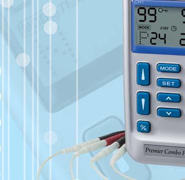
5 Chapter 4 : WARNINGS Chapter 7 : CONSTRUCTION 1. The long-term effects of chronic electrical stimulation are unknown. 2. Stimulation should not be applied over the carotid sinus nerves, particularly in patients with a known sensitivity to the carotid sinus reflex. 3. Stimulation should not be applied over the neck or mouth. Severe spasm of the laryngeal and pharyngeal muscles may occur and the contractions may be strong enough to close the airway or cause difficulty in breathing. 4. Stimulation should not be applied transthoracically in that the introduction of electrical current into the heart may cause cardiac arrhythmias. 5. Stimulation should not be applied transcerebrally. 6. Stimulation should not be applied over swollen, infected, or inflamed areas or skin eruptions, e.g., phlebitis, thrombophlebitis, varicose veins, etc. 7. Stimulation should not be applied over, or in proximity to, cancerous lesions. Chapter 5: CONTRAINDICATION Electrical stimulators should not be used on patients with cardiac demand pacemakers. Chapter 6: ADVERSE REACTIONS On rare occasions skin irritation and burns beneath the electrodes have been reported with the use of electrical stimulators. If irritation occurs, discontinue use and consult your physician. 6 FRONT (1) LEAD CONNECTOR (2) ON/OFF/PAUSE CONTROL (3) LIQUID CRYSTAL DISPLAY (4) MODE CONTROL (5) SET CONTROL (6) SETTING INCREMENT CONTROL (7) SETTING DECREMENT CONTROL (8) INTENSITY INCREMENT CONTROL (9) INTENSITY DECREMENT CONTROL 7
6 BACK BACK (10) BELT CLIP (11) BATTERY STRIP (12) BATTERY CASE SIDE (13) KEY LOCK FACILITY Liquid Crystal Display 1. INTENSITY LEVEL 2. MODE 3. SETTINGS 4. STIMULATION TYPE 5. LOW BATTERY INDICATOR 6. LOCK 8 SIDE Chapter 8 : TECHNICAL SPECIFICATIONS The technical specification details of Premier Combo Plus Digital TENS/EMS are as follows: MECHANISM TECHNICAL DESCRIPTION 01 Channel Dual, isolated between channels 02 Pulse Amplitude Adjustable, ma peak into 500 ohm load each channel. 03 Wave Form Asymmetrical Bi-Phasic Square Pulse 04 Voltage 0 to 50V (Load: 500 ohm) 05 Power source One 9 Volt Battery. 06 Size 11.8cm(L) x 6 cm(w) x 3.1cm(H) 07 Weight 157 grams with battery. 08 Pulse Rate Adjustable, from 2 to 150 Hz, 1 Hz/step 09 Pulse Width Adjustable, from 50 to 300 microseconds, 10 µs/step 10 On Time Adjustable, 2~90 seconds, 1 Sec./ step 11 Off Time Adjustable, 2~90 seconds, 1 Sec./ step 12 Ramp Time Adjustable, 1~8 seconds, 1 Sec./ step, The On time will increase and decrease in the setting value. 13 Mode Six TENS Modes: B(Burst), N(Normal),M (Modulation Rate & Width),S1( Modulation Width), S2 (Modulation Width) and P Three EMS Modes:C(Constant), S (Synchronous), A(Alternate) 14 Burst Mode Burst rate: Adjustable, 0.5 5Hz Pulse width adjustable, 50~300µs Frequency fixed = 100 Hz 15 Normal Mode The pulse rate and pulse width are adjustable. It generates continuous stimulation based on the setting value. 16 Modulation Mode Modulation mode is a combination of pulse rate and pulse width modulation. The pulse rate and width are automatically varied in a cycle pattern. The pulse width is decreased by 50% from its original setting 9
7 in 0.5 second, then the pulse rate is decreased by 50% from its original setting in 0.5 second. Total cycle time is 1 second. In this mode, pulse rate(2-150hz) and pulse width(50-300µs) are fully adjustable. 17 S1 Mode Pulse width is automatically varied in a cyclic pattern over a nominal 10 second period. Pulse width decreases over a period of 4 seconds from the initial setting to a value 40% less. The narrower pulse width continues for 1 second. It then increases over a period of 4 seconds to its initial setting. The cycle is then repeated. Pulse rate and pulse width are fully adjustable. 18 S2 Mode Pulse width is automatically varied in a cyclic pattern over a nominal 10 second period. Pulse width decreases over a period of 4 seconds from the initial setting to a value 70% less. The narrower pulse width continues for 1 second. It then increases over a period of 4 seconds to its initial setting. The cycle is then repeated. Pulse rate and pulse width are fully adjustable. 19 Constant The pulse rate and pulse width are Mode(C) adjustable. It generates continuous stimulation is delivered. 20 Synchronous Output from both channels occurs Mode(S) synchronously. The "ON" time includes "Ramp Up" and "Ramp Down" time. Therefore, the setting of ON Time should be no less than two times of the "Ramp" time in this mode. 21 Alternate The stimulation of the CH2 will occur after Mode(A) the 1st contraction of CH1 is completed. In this mode, the setting of ON Time should be no less than two times of the "Ramp" 10 time. The OFF Time should be equal to or greater than the ON Time. ON TIME Ramp up + Ramp down OFF TIME ON TIME 22 Mode P The pre-set parameters of the 24 programs are as given below: Program The pre-set parameters of the TENS 1-12 Details programs are as given below: Program Mode Pulse Rate Pulse Width Timer P1 Constant 80Hz 180µs Continue P2 Burst 2Hz 180µs Continue P3 P.W. 80Hz 70µs -180µs Continue Modulation P4 Mixed 15Hz in 3 Sec / 180µs Continue Frequency 2Hz in 3 Sec P5 Mixed 80Hz in 3 Sec / 180µs Continue Frequency 2Hz in 3 Sec P6 Constant 10Hz 180µs Continue P7 Constant 80Hz 60µs Continue P8 Constant 10Hz 200µs 30 Minutes P9 Burst 50Hz 250µs 30 Minutes P10 on Time Pause Time Frequency Pulse Width Sub- Active Pulse (sec) (sec) (Hz) (µs) Pulse Channels Polarity No CH1 & CH2 Positive No CH1 & CH2 Positive No CH1 & CH2 Positive No CH1 & CH2 Positive No CH1 & CH2 Positive No CH1 & CH2 Positive No CH1 & CH2 Positive No CH1 & CH2 Positive No CH1 & CH2 Positive 11
8 No CH1 & CH2 Positive No CH1 & CH2 Positive No CH1 & CH2 Positive No CH1 & CH2 Positive No CH1 & CH2 Positive No CH1 & CH2 Positive No CH1 & CH2 Positive No CH1 & CH2 Positive No CH1 & CH2 Positive No CH1 & CH2 Positive No CH1 & CH2 Positive No CH1 & CH2 Positive P11 Modulation 2-100Hz 260µs-150µs Continue Rate & width over 6 seconds P12 Modulation 80< - >7Hz 260µs Continue Rate & width over 6 seconds Program The pre-set parameters of the EMS Details programs are as given below: Mode SYN/ Rate Width Ramp ON Time Off Time Timer ALT (Hz) (µs) (Sec) (Sec) (Sec) (Min) P13 ACL repair/joint SYN protection back muscle P20 Muscle training SYN P21 Muscle training SYN P22 Muscle training SYN P23 Muscle training ALT P24 Muscle training ALT Timer Adjustable, from 5 to 60 minutes minutes and continue(c), 5 minutes each step 24 Patient This unit can store 60 sets of operation Compliance Meter records. Total recorded time is 999 hours. 25 Low Battery A low battery indicator will show up when Indicator the battery is low. 26 Operating Temperature:0 ~40 C Condition Relative Humidity: 30%~75% Atmosphere Pressure : 700Hpa~1060Hpa 27 Remark There may be up to a +/-10% tolerance of all parameters and +/-20% tolerance of output amplitude & voltage. P14 Spasm small SYN muscle P15 Spasm SYN Postoperative P16 Arthroscopy SYN P17 Disuse atrophy SYN P18 Shoulder SYN Subluxation P19 Range of motion SYN muscle re-education of hips 12 13

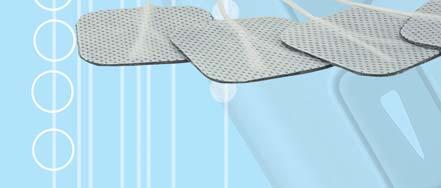
9 The waveforms of the TENS modes are as follows. 1. Burst Chapter 9 : REPLACEABLE PARTS The replaceable parts and accessories of Premier Combo Plus Digital TENS/EMS devices are as given below. Except lead wires and electrodes, please do not try to replace the other parts of a device. 2. Normal 3. Modulation PARTS 1. Lead Wires 2. Electrodes 3. Belt Clip 4. Lead Connector 5. Main PCB 6. Press Buttons 7. LCD Cover 8. 9V Battery 9. Device Case 4. S1 (Strength-Duration) Chapter 10 : ACCESSORIES Each Premier Combo Plus Digital TENS/EMS comes complete with standard accessories and the standard labels as given below: 5. S2 (Strength-Duration) I. Accessories REF. NO. DESCRIPTION Q TY 1. KF x40mm Adhesive Electrodes 4 pieces 2. KE-24 Electrodes Leads 2 pieces 3. GC-01 9 V Battery, type 6F22 1 piece 4. Instruction Manual 1 piece 5. Carrying Case 1 piece 14 15
 14. Comply with MDD 93/42/EEC requirements as amended by 2007/47/EC. Notify body Det Norske Veritas(DNV). 15. Power III.")
10 II. LABEL The label attached to the back of device contains important information about this devicemodel, supply voltage, CE number and caution. Please do not remove. 13. DC Current(DC Power source) 14. Comply with MDD 93/42/EEC requirements as amended by 2007/47/EC. Notify body Det Norske Veritas(DNV). 15. Power III. Serial Number(YYWWXXXX) The serial number of the device is put on the back of the unit. There are 8 digits in the number. The first 2 digits represent the year the unit is produced. For example, 16 means The second 2 digits means the week number. The last 4 digits means the serial number of unit produced in that week. Please always tell your distributor the serial number of the device if you have any question about the device. Chapter 11 : GRAPHIC SYMBOLS 1. Degree of Electrical Protection BF 2. Do not insert the plug into AC power supply socket. 3. Timer 4. Increment 5. Decrement 7. Consult Instructions for use 8. Manufacturer 9. Serial Number 10. Lock 11. Low Battery 12. Pause 16 Chapter 12: OPERATING INSTRUCTIONS 1) Insert the 9V battery into the device's battery compartment. Make sure that the plastic seal on the 9V battery is removed. Line up the positive and negative terminals on the battery with their corresponding terminals in the device. Make sure that the unit is turned off. 2) Insert the lead wires into the lead wire sockets on top of the device. 3) Open the electrode package. Then insert each lead wire pin into the pig tail of the electrodes 4) Place the electrode on your body as directed by your physician. 5) Turn on the power by pressing the power On/Off/Pause button. 6) Select the mode and settings as directed by your physician. 7) Slowly increase or decrease the intensity by pressing the intensity control buttons. 8) You may press the On/Off/Pause button if you want to stop treatment for a while. 9) After treatment, turn the device off by pressing the On/Off/Pause button. Chapter 13 : PARAMETER CONTROLS PULSE DURATION Wider pulse duration settings will deliver stronger stimulation for any given intensity setting. As mentioned in the Controls section, by 17
11 using a combination of intensity and pulse duration different nerve fibres are stimulated. The wider pulse duration is needed to recruit motor fibres, whereas the narrow pulse duration is used on the more sensory fibres. The choice of which pulse duration to use is partially dependent upon the Treatment Mode and Protocol selected. PULSE RATE The Pulse Rate (hertz or pulses per second) chosen depends greatly upon the type of electrode placement given to the patient. When using contiguous and dermatome electrode placements (i.e. stimulating directly through the area of pain or localized innnervation), a higher pulse rate (setting greater than 80Hz on the Pulse Rate Control) is required. The patient should not perceive individual pulses but rather have the sensation of steady continuous stimulation. When using point treatments, it has been suggested that lower pulse rates be utilized (less than 10Hz). With this setting the patient should be able to perceive individual pulses. When using multiple electrode placement strategies, such as combinations of point and contiguous electrode placements, the higher pulse rates are suggested. Despite the above recommendations, individual patients may require slight variations of the above settings, according to the nature of their condition. TREATMENT MODE Normal or Conventional TENS offers the practitioners complete control over all the various treatment parameters of the instrument. Burst Mode is analogous to the Low Rate TENS technique except the low frequency individual pulses are replaced by individual bursts of 7-10 individual pulses. It is thus a combination of Conventional TENS and Low Rate TENS. In Burst Mode, the treatment frequency is adjustable at the range between 0.5Hz ~ 5Hz. Modulated Mode attempts to minimise nerve accommodation by continuously cycling the treatment intensity. Advise the patient to increase the intensity very slowly when using modulation mode. 18 INTENSITY Each patient responds differently to different levels of intensity, due to varying degrees of tissue resistance, enervation, skin thickness, etc. Intensity instructions are therefore limited to the following settings: Perception The intensity is increased so that the patient can feel the stimulation, but there is not any muscular contraction. Slight Contraction Intensity is increased to a barely visible muscular contraction that is not strong enough to move a joint. When using low pulse rate settings, this will show as individual twitches. At higher pulse rates there will simply be increased muscle tension. Strong muscular contraction is typically not used in TENS therapy. However, muscular contraction may be useful if the pain involves a cramped or spastic muscle. The TENS can be used as a traditional muscle stimulator in the circumstances to quickly break the spasm. Use a higher pulse rate, wide pulse duration and set the intensity to visible contraction (still within patient tolerance). Twenty or thirty minutes of such a tetanized muscular contraction will generally break the spasm. In all cases, if the patient complains that the stimulation is uncomfortable, reduce intensity and/or cease stimulation. TIME DURATION The onset of pain relief should occur shortly after the intensity setting has been determined. However, in some cases, pain relief may take as long as 30 minutes to achieve, especially when using point electrode placements and slow pulse rates. TENS units are typically operated for long periods of time, with a minimum of 20 ~ 30 minutes and in some post-operation protocols, as long as 36 hours. In general, pain relief will diminish within 30 minutes of the cessation of stimulation. Pain relief obtained through point electrode placements may last longer (perhaps because of the presence of endorphins). 19
12 CONTRACTION / RELAXATION The contraction time and relaxation time of EMS is adjustable. Stimulation will commence at the contraction setting time and cease at the relaxation setting time. Then the cycle starts over again - Stimulation, Contraction and Relaxation. RAMP In order to achieve a comfortable exercise and avoid discomfort because of immediate current onset, each contraction may be ramped so that the signal comes on gradually and smoothly. The intensity of electrical current will reach the set level within the Ramp time. It will NOT reach the desired level if the ramp time is greater than the total contraction time. OUTPUT MODE The output of both channels are adjustable. Stimulation can be synchronous or alternate. Stimulation of both channels will occur at the same time when synchronus pattern is selected. In alternating mode, the stimulation from CH2 will occur after contraction of Ch1 is finished. Chapter 14 : ATTACHMENT OF ELECTRODE The wires provided with the system insert into the jack sockets located on top of the device. Holding the insulated portion of the connector, push the plug end of the wire into one of the jacks (see drawing); one or two sets of wires may be used. LEAD WIRES 20 After connecting the wires to the stimulator, attach each wire to an electrode. Use care when you plug and unplug the wires. Jerking the wire instead of holding the insulated connector body may cause wire breakage. CAUTION Do not insert the plug of the patient lead wire into any AC power supply socket. Chapter 15: LEAD WIRE MAINTENANCE Clean the wires by wiping with a damp cloth. Coating them lightly with talcum powder will reduce tangling and prolong life. Chapter 16 : ELECTRODE OPTIONS The electrodes are disposable and should be routinely replaced when they start to lose their adhesive nature. If you are unsure of your electrode adhesive properties, order replacement electrodes. Replacement electrodes should be re-ordered through or on the advice of your physician to ensure proper quality. Follow application procedures outlined in electrode packing, to maintain optimal stimulation and to prevent skin irritation. Chapter 17: ELECTRODE PLACEMENT The placement of electrodes can be one of the most important parameters in achieving success with TENS or EMS therapy. It is important that the physician experiments to determine optimum electrode placement. Every patient responds to electrical stimulation differently and their needs may vary from the conventional settings suggested here. If 21
13 the initial results are not positive, speak to your physician about alternative stimulation settings and/or electrode placements. Once an acceptable placement has been achieved, mark the electrode sites and the settings, so that effective treatment may effectively continue at home. Chapter 18: TIPS FOR SKIN CARE To avoid skin irritation, especially if you have sensitive skin, follow these suggestions: 1. Wash the area of skin where you will be placing the electrodes, using mild soap and water before applying electrodes, and after taking them off. Be sure to rinse soap off thoroughly and dry skin well. 2. Excess hair may be clipped with scissors; do not shave stimulation area. 3. Wipe the area with the skin preparation your physician has recommended. Let this dry. Apply electrodes as directed. 4. Many skin problems arise from the pulling stress from adhesive patches that are excessively stretched across the skin during application. To prevent this, apply electrodes from center outward; avoid stretching over the skin. 5. To minimize pulling stress, tape extra lengths of lead wires to the skin in a loop to prevent tugging on electrodes. 6. When removing electrodes, always remove by pulling in the direction of hair growth. 7. It may be helpful to rub skin lotion on electrode placement area when not wearing electrodes. 8. Never apply electrodes over irritated or broken skin. Chapter 19: APPLICATION OF RE-USABLE SELF Application ADHESIVE ELECTRODES 1. Clean and dry the skin at the prescribed area thoroughly with 22 soap and water prior to application of electrodes. 2. Insert the lead wire into the pin connector on the pre-wired electrodes. 3. Remove the electrodes from the protective liner and apply the electrodes firmly to the treatment site. Make sure that the unit is turned off prior to applying the electrodes. Removal 1. Turn off the unit prior to removing the electrodes. 2. Lift at the edge of electrodes and peel; do not pull on the lead wires because it may damage the electrodes. 3. Place the electrodes on the liner and remove the lead wire by twisting and pulling at the same time. Care and Storage 1. Between uses, store the electrodes in the resealable bag in a cool dry place. 2. It may be helpful to improve repeated application by spreading a few drops of cold water over the adhesive and turn the surface up to air dry. Over Saturation with water will reduce the adhesive properties. Important 1. Do not apply to broken skin. 2. The electrodes should be discarded and re-ordered from your physician when they are no longer adhering. 3. The electrodes are intended for single patient use only. 4. If irritation occurs, discontinue use and consult your physician. 5. Read the instructions for use of self-adhesive electrodes before application. 23

14 Chapter 20 : ADJUSTING THE CONTROLS 1. Power On/Off/Pause Button The power of unit can be turned on by pressing the On/Off/ Pause button. You may start to adjust the settings when the liquid crystal is light up. Press and hold for 2 seconds to switch off. To pause stimulation press the button once. To resume stimulation press the button again and stimulation will be restored in 2 seconds. If the unit is not used (buttons not pressed or output level at 0) for 5 minutes, the power will be shut off automatically. If the unit is not used(buttons not pressed or output level at 0) for 5 minutes, the power will be shut off automatically 2. Lead Connector Connection of the electrodes is made with the two-lead connector (lead wires) on the top of unit. The device must be turned off before connecting the cables. Electrodes must be in firm contact with the skin. 24 Pause 3 Mode Control There are 5 TENS modes(b, N, M, S1, S2) and 3 EMS modes (C, S, A) available. The mode is selected by pressing the Mode control. When a TENS mode is selected, the LCD shows "TENS". When EMS mode is selected, the LCD shows "EMS" 4. Set Control By pressing the "Set" control you select the setting you intend to adjust. The value is set by pressing the "Increment" or "Decrement" controls when the "Set" value is flashing. 5. Increment Control This button controls the increase of settings. 6. Decrement Control This button controls the decrease of settings. 7. Intensity Increase Control The intensity level can be increased by pressing this button. There are 99 steps of intensity adjustment control. Press the button until the desired intensity level is reached. 8. Intensity Decrease Control The intensity level can be decreased by pressing this button. There are 99 steps of intensity adjustment control. Press the button until the desired intensity level is reached. 9. Key Lock Facility Pressing the "Lock" buttons prevents the settings 25
15 being changed but the output may be stopped by pressing the "On/Off/Pause". 10. Steps to Set a TENS Program The settings can be adjusted as follows a. Turn on the Power After the electrodes are placed firmly on skin and the lead wires are plugged in the socket of device, turn the unit on by pressing the On/Off/Pause button. The settings will be displayed on the LCD screen. b. Select a Mode or a Preset Programme Select a mode by pressing the "Mode" control. The mode you selected will show up on the top of liquid crystal display. There are 5 modes of your option including - B(Burst), M(Normal), M(Modulation), S1, S2 and P. When a TENS mode is selected, it shows "TENS" on the liquid crystal display. c. Set Pulse Width Pulse Width is adjustable from 50 µs to 300 µs. Press SET control to enter this menu, then press or to adjust the setting. If no instructions regarding the pulse width are given in therapy, set the control to the suggested µs setting. d. Set Pulse Rate Pulse rate is adjustable from 2Hz to 150 Hz. Press "SET" control to enter this menu, then press " " or " " to adjust the setting. Unless otherwise instructed, set the pulse rate l to the Hz range. After a mode is selected, always press "Set" to enter next setting, and press " " or " " to adjust its value. The settings will be stored immediately after selected. There are 12 preset programs of your option on P mode. Press " " or " " to select a program desired after P mode is selected. These programs are not adjustable. e. Set Timer The treatment time is adjustable between 5-60 minutes and Continue(C). Press "SET" control to enter this menu, then press " " or " " to adjust the setting. The liquid crystal will show the balance treatment time after the stimulation is started. Output will be terminated when time is up. Turn off the unit when the output is off. Continuous End of Treatment 26 27

16 f. Adjust Intensity There are 99 steps within the intensity range. Set the desired level by pressing the " " or " " controls. Press the "Lock" button to prevent accidental changes. setting, and press or to adjust its value. The settings will be stored immediately after selected. There are 12 preset programs of your option on P mode. Press or to select a program desired after P mode is selected. These programs are not adjustable. 11. Steps to Set a EMS Program The settings can be adjusted according to the following steps. a. Turn on the Power After the electrodes are placed firmly on skin and the lead wires are plugged in the socket of device, turn the unit on by pressing the On/Off/Pause button. The settings will show up on LCD for your further adjustment. b. Select a Mode or a Preset Programme Select a mode by pressing the "Mode" control. The mode you selected will show up on the top of liquid crystal display. There are 3modes of your option including - C(Constant), S(Synchronous), A(Alternate). When an EMS mode is selected, it shows "EMS" on the liquid crystal display. After a mode is selected, always press "Set" to enter next setting, and press " " or " " to adjust its value. The settings will be stored immediately after selected. c. Set Ramp Time The ramp time controls the time taken to reach maximum and the time taken to fall to zero I order to make the contraction more comfortable. The ramp time is adjustable between 1-8 seconds. d. Set On Time The On Time controls the length of stimulation. By pressing the "Set" control, the contraction time can be adjusted. Both channels' stimulation is cycled on and off by the contraction and relaxation settings. The range is adjustable from 2 seconds to 90 seconds. The total "ON" time must be at least twice the "Ramp" time After a mode is selected, always press Set to enter next 28 29
17 e. Set Off Time The Off Time controls the length of relaxation. By pressing the "SET" control, the relaxation time can be adjusted. Both channels' stimulation is cycled on and off by the contraction and relaxation settings. The range is adjustable from 2 seconds to 90 seconds. In Alternate mode, the OFF Time should be equal or more than the ON Time. (OFF TIME ON TIME) h. Set Timer The treatment time is adjustable between 5-60 minutes and Continue(C). Press "SET" control to enter this menu, then press "Increment" or "Decrement" to adjust the setting. The liquid crystal will show the balance treatment time after the stimulation is started. Output will be terminated when time is up. Turn off the unit when the output is off. Continuous End of Treatment f. Set Pulse Width Pulse Width is adjustable from 50 µs to 300 µs. Press "SET" control to enter this menu, then press " " or " " to adjust the setting. If no instructions regarding the pulse width are given in therapy, set the control to the suggested µs setting i. Adjust Intensity There are 99 steps within the intensity range. Set the desired level by pressing the " " or " " controls. Press the "Lock" button to prevent accidental changes. g. Set Pulse Rate Pulse rate is adjustable from 2Hz to 150 Hz. Press "SET" control to enter this menu, then press " "or " " to adjust the setting. Unless otherwise instructed, set the pulse rate to the Hz range Compliance Meter The individual treatment time and total treatment time can be checked and deleted by the following steps. Sixty sets of treatment records can be stored. Total recorded time is 999 hours. Check & Delete Treatment Record Press "Mode" control and turn on the power simultaneously. The LCD will show the individual operation time. Press "Mode" control to check the accumulated treatment time. The record can be deleted by pressing the "SET" button for two seconds. 31
18 13. Check/Replace the Battery: Over time, in order to ensure the functional safety of TENS/ EMS, changing the battery is necessary. 1. Make sure that both intensity controls are switched to off position. 2. Slide the battery compartment cover and open. 3. Remove the battery from the compartment. 4. Insert the battery into the compartment. Note the polarity indicated on the battery and in the compartment. 5. Replace the battery compartment cover and press to close. PRECATIONS Individnal Record Chapter 21: BATTERY INFORMATION 1. Remove battery if equipment is not likely to be used for some time. 2. Please recycle the used battery in accordance with domestic regulation. 3. Do not throw the used battery into fire. If you use rechargeable batteries, please follow the instructions. 32 Accumulated RECHARGEABLE BATTERIES(NOT INCLUDED) Prior to the use of a new unit, the rechargeable battery should be charged according to the battery manufacturer s instructions. Before using the battery charger, read all instructions and cautionary markings on the battery and in this instruction manual. After being stored for 60 days or more, the batteries may lose their charge. After long periods of storage, batteries should be charged prior to use. BATTERY CHARGING (1) Plug the charger into any working 110 or 220/240v mains electrical outlet. The use of any attachment not supplied with the charger may result in the risk of fire, electric shock, or injury to persons. (2) Follow the battery manufacturer s instructions for charging time. (3) After the battery manufacturer s recommended charging time has been completed, unplug the charger and remove the battery. (4) Batteries should always be stored in a fully charged state. To ensure optimum battery performance, follow these guidelines: (a) Although overcharging the batteries for up to 24 hours will not damage them, repeated overcharging may decrease useful battery life. (b) Always store batteries in their charged condition. After a battery has been discharged, recharge it as soon as possible. If the battery is stored more than 60 days, it may need to be recharged. (c) Do not short the terminals of the battery. This will cause the battery to get hot and can cause permanent damage. Avoid storing the batteries in your pocket or purse where the terminals may accidentally come into contact with coins, keys or any metal objects. (d) WARNINGS: 1. Do not attempt to charge any other types of batteries in your charger, other than rechargeable batteries made 33
19 for your charger. Other types of batteries may leak or burst. 2. Do not incinerate the rechargeable battery as it may explode! Chapter 22 : MAINTENANCE, TRANSPORTATION AND STORAGE 1. Non-flammable cleaning solution is suitable for cleaning the device. Note: Do not smoke or work with open lights (for example, candles, etc.) when working with flammable liquids. 2. Stains and spots can be removed with a cleaning agent. 3. Do not submerge the device in liquids or expose it to large amounts of water. 4. Return the device to the carrying box with sponge foam to ensure that the unit is well-protected before transportation. 5. If the device is not to be used for a long period of time, remove the batteries from the battery compartment (acid may leak from used batteries and damage the device). Put the device and accessories in carrying box and keep it in cool dry place. 6. The packed device should be stored and transported under the temperature range of -20 C ~ + 60 C, relative humidity 20% ~95%, atmosphere pressure 500 hpa ~ 1060 hpa. Chapter 23: SAFETY-TECHNICAL CONTROLS For safety reasons, review the following checklist before using your Premier Combo Plus DIGITAL TENS/EMS. 1. Check the device for external damage. - deformation of the housing. - damaged or defective output sockets. 2. Check the device for defective operating elements. - legibility of inscriptions and labels. - make sure the inscriptions and labels are not distorted Check the usability of accessories. - patient cable undamaged. - electrodes undamaged. - Battery is not corroded Please consult your distributor if there are any problems with device and accessories. Chapter 24 : MALFUNCTIONS Should any malfunctions occur while using the Premier Combo Plus Digital TENS/EMS, check - whether the parameters are set to the appropriate form of therapy. Adjust the control correctly. - whether the cable is correctly connected to the device. The cables should be inserted completely into the sockets. - whether the LCD reveals the menu. If necessary, insert a new battery. - for possible damage to the cable. Change the cable if any damage is detected. * If there is any other problem, please return the device to your distributor. Do not try to repair a defective device. Chapter 25: CONFORMITY TO SAFETY STANDARDS The Premier Combo Plus DIGITAL TENS/EMS devices are in compliance with the following standards. EN :2007, IEC :2007 Medical electrical equipment - Part 1-2: General requirements for basic safety and essential performance 35
20 -Collateral standard: Electromagnetic compatibility - Requirements and tests EN :2006, IEC :2005 Medical electrical equipment - Part 1: General requirements for basic safety and essential Performance Chapter 26 : WARRANTY All Premier Combo Plus Digital TENS/EMS models carry a warranty of one year from the date of delivery. The warranty applies to the stimulator only and covers both parts and labour relating thereto. The warranty does not apply to damage resulting from failure to follow the operating instructions, accidents, abuse, alteration or disassembly by unauthorized personnel. Chapter 27: ELECTROMAGNETIC COMPATIBILITY INFORMATION The device complies with current specifications with regard to electromagnetic compatibility and is suitable for use in all premises, including those designated for private residential purposes. The radio frequency emissions of the device are extremely low and in all probability do not cause any interference with other devices in the proximity.it is recommended that you do not place the device on top of or close to other electronic devices. Should you notice any interference with other electrical devices, move the device or connect it to a different socket. Radio equipment may affect the operation of this device. Guidance and manufacturer s declaration - electromagnetic emissions The EM-6300A is intended for use in the electromagnetic environment specified below. The customer or the user of the EM-6300A should assure that it is used in such an environment. CISPR 11 Emissions test Compliance Electromagnetic environment - guidance RF emissions Group 1 The EM-6300A must emit electromagnetic energy in order to perform its intended function. Nearby electronic equipment may be affected. RF emissions Class B The EM-6300A is suitable for use in all CISPR 11 Harmonic emissions Class C IEC Voltage fluctuations Complies / flicker emissions purposes. IEC establishments other than domestic those directly connected to the public low-voltage power supply network that supplies buildings used for domestic 36 37
21 Guidance and manufacturer s declaration - electromagnetic immunity The EM-6300A is intended for use in the electromagnetic environment specified below. The customer or the user of the EM-6300A should assure that it is used in such an environment. IMMUNITY test Electrostatic discharge (ESD) IEC Power frequency (50/60 Hz) magnetic field IEC IEC test level ± 6 kv contact ± 8 kv air (>95 % dip in UT) (>95 % dip in UT) for 5 s 3 A/m Compliance level ± 6 kv contact ± 8 kv air for 5 s Not applicable Electromagnetic environment - guidance Floors should be wood, concrete or ceramic tile. If floors are covered with synthetic material, the relative humidity should be at least 30 %. Electrical fast transient/burst IEC Surge IEC ± 2 kv for power supply lines ± 1 kv line(s) to line(s) and neutral ± 2 kv for power supply lines ± 1 kv line(s) to line(s) and neutral Mains power quality should be that of a typical commercial or hospital environment. Mains power quality should be that of a typical commercial or hospital environment. Voltage dips, short <5 % UT <5 % UT Mains power quality should be that interruptions and (>95 % dip in UT) (>95 % dip in UT) of a typical commercial or hospital voltage variations on for 0,5 cycle for 0,5 cycle environment. If the user of the power supply input lines IEC % UT (60 % dip in UT) for 5 cycles 40 % UT (60 % dip in UT) for 5 cycles EM-6300A requires continued operation during power mains interruptions, it is recommended 70 % UT 70 % UT that the EM-6300A be powered (30 % dip in UT) (30 % dip in UT) from an uninterruptible power for 25 cycles for 25 cycles supply or a battery. <5 % UT <5 % UT Not applicable NOTE UT is the a.c. mains voltage prior to application of the test level. Guidance and manufacturer s declaration - electromagnetic immunity The EM-6300A is intended for use in the electromagnetic environment specified below. The customer or the user of the EM-6300A should assure that it is used in such an environment. IMMUNITY test IEC test Compliance level Electromagnetic environment. guidance Conducted RF IEC Radiated RF IEC level 3 Vrms 150 khz to 80 MHz 3 V/m 80 MHz to 2,5 GHz 3 Vrms 3 V/m Portable and mobile RF communications equipment should be used no closer to any part of the EM-6300A, including cables, than the recommended separation distance calculated from the equation applicable to the frequency of the transmitter. Recommended separation distance d = 1,2 P d = 1,2 P 80 MHz bis 800 MHz d = 2,3 P 800 MHz bis 2,5 GHz where P is the maximum output power rating of the transmitter in watts (W) according to the transmitter manufacturer and d is the recommended separation distance in meters (m). Field strengths from fixed RF transmitters, as determined by an electromagnetic site survey. Interference may occur in the vicinity of equipment marked with the following symbol: NOTE 1 At 80 MHz and 800 MHz, the higher frequency range applies. NOTE 2 These guidelines may not apply in all situations. Electromagnetic propagation is affected by absorption and reflection from structures, objects and people. a Field strengths from fixed transmitters, such as base stations for radio (cellular/cordless) telephones and land mobile radios, amateur radio, AM and FM radio broadcast and TV broadcast cannot be predicted theoretically with accuracy. To assess the electromagnetic environment due to fixed RF transmitters, an electromagnetic site survey should be considered. If the measured field strength in the location in which the EM-6300A is used exceeds the applicable RF compliance level above, the EM-6300A should be observed to verify normal operation. If abnormal performance is observed, additional measures may be necessary, such as re-orienting or relocating the EM-6300A. b Over the frequency range 150 khz to 80 MHz, field strengths should be less than 3 V/m
22 Recommended separation distances between portable and mobile RF communications equipment and the EM-6300A (Appendix I) Test Environment The EM-6300A is intended for use in an electromagnetic environment in which radiated RF disturbances are controlled. The customer or the user of the EM-6300A can help prevent electromagnetic interference by maintaining a minimum distance between portable and mobile RF communications equipment (transmitters) and the EM-6300A as recommended below, according to the maximum output power of the communications equipment. Rated maximum Separation distance according to frequency of transmitter output power of transmitter m 150KHz bis 800MHz 80MHz bis 800MHz 80MHz bis 2.5GHz W d = 1,2 P d = 1,2 P d = 2,3 P 0,01 0,12 0,12 0,23 0,1 0,38 1 1,2 10 3, ,38 0,73 1, , For transmitters rated at a maximum output power not listed above, the recommended separation distance in metres (m) can be estimated using the equation applicable to the frequency of the transmitter, where P is the maximum output power rating of the transmitter in watts (W) according to the transmitter manufacturer. NOTE 1 At 80 MHz and 800 MHz, the separation distance for the higher frequency range applies. NOTE 2 These guidelines may not apply in all situations. Electromagnetic propagation is affected by absorption and reflection from structures, objects and people
 Load: 500 ohm Pulse Rate: 150Hz Pulse Width:")


23 (Appendix II) Waveform of EM-6300A Digital TENS/EMS TENS 1. B Mode(Burst) Load: 500 ohm Pulse Rate: 150Hz Pulse Width: 300µs Scope A : VERT:10.0V/DIV HORIZ:2mS OUTPUT: Vpk-pk Pulse Rate:100Hz 2. N MODE(Normal): Load: 500 ohm Pulse Rate: 150Hz Pulse Width: 300µs Scope A : VERT:10.0V/DIV HORIZ:2mS OUTPUT: V pk-pk Pulse Rate:148.8Hz Scope B: VERT:10.0V/DIV HORIZ:50mS Pulse Rate:5.000Hz Scope B : VERT:10.0V/DIV HORIZ:100µs OUTPUT: V pk-pk Pulse Width:300µs 42 43


24 3. M MODE(-50% Pulse Width & Rate Modulation): Load:500 ohm Pulse Rate:150Hz Pulse Width:300µs 4. S1 MODE(-40% Pulse Width Modulation): Load: 500 ohm Pulse Rate: 150Hz Pulse Width: 300 µs Scope A: VERT:10.0V/DIV HORIZ:100µs OUTPUT: Vpk-pk Pulse width:300µs Scope A: VERT: 20.0V/DIV HORIZ: 200 µs OUTPUT: 50.0V pk-pk Pulse width: 184 µs Scope B: VERT:10.0V/DIV HORIZ:100µs OUTPUT: V pk-pk Pulse width:150µs Scope C: Scope B: VERT: 20.0V/DIV HORIZ: 200 µs OUTPUT: 56.9V pk-pk Pulse width: 302 µs Modulation: -50% 44 45


25 5. S2 MODE(-70% Pulse Width Modulation): Load: 500 ohm Pulse Rate : 150Hz Pulse Width: 300µs Scope A: VERT: 20.0V/DIV HORIZ: 200µs OUTPUT: 48.8Vpk-pk Pulse width: 124µs EMS 1. C MODE : Load: 500 ohm Pulse Rate : 150Hz Pulse Width: 300 µs Scope A: VERT:10.0V/DIV HORIZ: 2mS OUTPUT: V pk-pk Pulse Rate:148.8Hz Scope B: VERT: 20.0V/DIV HORIZ: 200µs OUTPUT: 56.9Vpk-pk Pulse width: 302 µs Scope B: VERT:10.0V/DIV HORIZ:100µs OUTPUT: V pk-pk PulseWidth:300µs 46 47

: Load: 500 ohm Pulse Rate :150Hz Pulse")
26 2. S MODE(Synchronous): Load:500 ohm Pulse Rate:150Hz Pulse Width:300µs Contratction Time:12 Sec Relation Time:12 Sec Ramp Time:6 Sec 3. A MODE(Alternate): Load: 500 ohm Pulse Rate :150Hz Pulse Width:300µs Contratction Time :12 Sec Relation Time:12 Sec Ramp Time: 6 Sec 48
INSTRUCTION MANUAL FOR THE. Premier TENS
 INSTRUCTION MANUAL FOR THE Premier TENS 0434 INDEX Chapter Contents Page 1. General Description... 2 2. Introduction... 2 3. Cautions... 3 4. Warnings... 4 5. Contraindications... 5 6. Adverse Reactions...
INDEX. Chapter Contents Page
 INDEX Chapter Contents Page 1. Introduction... 2 2. Cautions... 3 3. Warnings... 4 4. Contraindications... 5 5. Adverse Reactions... 5 6. General Description... 5 7. Construction... 6 8. Technical Specifications...
INSTRUCTION MANUAL FOR THE
 INSTRUCTION MANUAL FOR THE PAIN-CARE TENS Distributed by: V1.0 0434 INDEX Chapter Contents Page 1. General Description...2 2. Introduction...2 3. Cautions...3 4. Warnings...4 5. Contraindications...5 6.
Transcutaneous Electrical Nerve Stimulator TENS 212. Instruction Manual. Read before using
 Transcutaneous Electrical Nerve Stimulator TENS 212 Instruction Manual Read before using TABLE OF CONTENTS GENERAL DESCRIPTION 1 SYSTEM COMPONENTS 1 WARRANTY 1 INDICATIONS AND CONTRAINDICATIONS 2 WARNINGS
INDEX. Chapter Contents
 CMYK INDEX Chapter Contents Page Index....1 1. Introduction... 2 2. Cautions... 3 3. Warnings... 4 4. General Description... 4 5. Construction.....5 6. Technical Specifications...... 6 7. Replaceable Parts....
INDEX. Chapter Contents
 INDEX Chapter Contents Page Index....1 1. Introduction. 2 2. Cautions.. 2 3. Warnings.. 3 4. General Description... 4 5. Construction......5 6. Technical Specifications...6 7. Replaceable Parts......7
Pain Management System
 TM Pain Management System Model: ireliev Model #: ET-1313 Operating & Instruction Manual Read Before Using ireliev Pain Management System Intended Use The ireliev Pain Management System (Model # ET-1313)
INTRODUCTION. It is also intended for symptomatic relief and management of chronic, intractable pain and relief of pain associated with arthritis.
 TENS / HEAT 1 2 TABLE OF CONTENTS Introduction...4 Indications for Use...4 Safety Warning...5 Contraindications...5 Warnings...5 Precautions...6 Adverse Reactions...8 Symbol and Title...8 Environmental
Powered Traction Unit OPERATION MANUAL
 Powered Traction Unit OPERATION MANUAL CONTENTS Symbols Safety precautions Symbol for CAUTION Symbol for CONSULT INSTRUCTIONS FOR USE Symbol for SERIAL NUMBER Symbol for CATALOGUE NUMBER Symbol for AUTHORISED
This manual is valid for the TM. In TENSity 5000 TENS Stimulator. This user manual is published by Current Solutions, LLC
 INSTRUCTION MANUAL This manual is valid for the TM In TENSity 5000 TENS Stimulator This user manual is published by Current Solutions, LLC Current Solutions, LLC does not guarantee its contents and reserves
User Manual. Before Using Your WiTouch Pro Device
 User Manual Before Using Your WiTouch Pro Device Sync the Remote Control and the WiTouch Pro Device. Using the provided screwdriver, remove the back cover from the WiTouch Pro device. 2. Remove the clear
D C 01/2019 3
 D-0117968-C 01/2019 3 4 D-0117968-C 01/2019 Screw Driver Screw Driver Unplug both the Red & Blue connectors. (see above) Place a small flat head screw driver on the small orange tabs and push down while
INTRODUCTION. 4 SAFETY INSTRUCTIONS. 5 ABOUT THIS DEVICE. 6 FIRST OPERATION. 7 THE DISPLAY. 8 ATTACHING THE WRIST SLEEVE. 9 CORRECT MEASUREMENT.
 Table of contents INTRODUCTION.............................. 4 SAFETY INSTRUCTIONS........................ 5 ABOUT THIS DEVICE.......................... 6 FIRST OPERATION............................ 7
BIODEX MULTI- JOINT SYSTEM
 BIODEX MULTI- JOINT SYSTEM CONFORMANCE TO STANDARDS 850-000, 840-000, 852-000 FN: 18-139 5/18 Contact information Manufactured by: Biodex Medical Systems, Inc. 20 Ramsey Road, Shirley, New York, 11967-4704
English
 English Specifications Type Power Source Vibration Frequency Maximum Output Power Consumption Water Pressure Lighting NE134 AC120V 50/60Hz AC230V 50/60Hz 28~32kHz 8W Max. 42VA 0.1~0.5MPa (1~5kgf/cm
Guidance and Declaration - Electromagnetic Compatibility (EMC) for the Delfi PTS ii Portable Tourniquet System
 for the Delfi PTS ii Portable Tourniquet System") Guidance and Declaration - Electromagnetic Compatibility (EMC) for the Delfi TS ii ortable Tourniquet System Guidance and manufacturer s declaration electromagnetic emissions The TS ii ortable Tourniquet
Guidance and Declaration - Electromagnetic Compatibility (EMC) for the Delfi TS ii ortable Tourniquet System Guidance and manufacturer s declaration electromagnetic emissions The TS ii ortable Tourniquet
Instruction Manual. CAUTION: Federal law requires a prescription from your physician before use of this product.
 Instruction Manual Please read the Instruction Manual prior to use. CAUTION: Federal law requires a prescription from your physician before use of this product. 3504 Cragmont Dr. Suite #100 Tampa, FL 33619
Biological Safety. Electromagnetic Compatibility (EMC) Observe the following precautions related to biological safety.
 Observe the following precautions related to biological safety.") Biological Safety Observe the following precautions related to biological safety. WARNING: Non-medical (commercial) grade peripheral monitors have not been verified or validated by SonoSite as being suitable
Biological Safety Observe the following precautions related to biological safety. WARNING: Non-medical (commercial) grade peripheral monitors have not been verified or validated by SonoSite as being suitable
HeRO duet
 HeRO duet CUSTOMER SERVICE TABLE OF CONTENTS TABLE OF CONTENTS OVERVIEW OVERVIEW OVERVIEW OVERVIEW USING HeRO duet USING HeRO duet USING HeRO duet Current HeRO Score HeRO USING HeRO duet USING HeRO duet
PHYSIOFLOW Q-LINK TM
 PHYSIOFLOW Q-LINK TM Service Manual Thursday, 20 October 2016 First placing on the market : 18 January 2012 User Manual PhysioFlow Q-Link 1/17 Table of contents 1. General Information... 3 About this manual...
Nursing Beds with Dewert drive system
 Nursing Beds with Dewert drive system GB Casa Med Classic 4 / Classic (FS) Casa Med Ultra / Ultra (FS) Casa Med Classic Low Casa Med Classic (FS) 4 / Classic / Casa FS Med / Casa Classic Med Low Ultra
User Instruction Computer Assisted Local Analgesia. 337 Marion, Le Gardeur QC, Canada, J5Z 4W8
 User Instruction Computer Assisted Local Analgesia 1-800-667-9622 337 Marion, Le Gardeur QC, Canada, J5Z 4W8 USER INSTRUCTION Congratulations on your new CALAJECT! Please read these instructions thoroughly
This manual is valid for the InTENSity TM Twin Stim III TENS/EMS Combo Stimulator
 INSTRUCTION MANUAL This manual is valid for the InTENSity TM Twin Stim III TENS/EMS Combo Stimulator This user manual is published by Compass Health Brands Corp. Compass Health Brands does not guarantee
Trio*Stim. Instruction Manual
 Trio*Stim Instruction Manual Please read this manual carefully before using the Trio*Stim. This manual is comprised as an essential part of the Trio*Stim. Save this manual in a designated place for your
General Safety/EMC and Electrical Information for i-limb ultra and i-limb digits
 1. General Safety 1.1 The i-limb ultra and i-limb digits devices are electrical devices, which under certain circumstances could present an electrical shock hazard to the user. Please read the accompanying
Electromagnetic compatibility Guidance and manufacturer s declaration DIN EN :2007 (IEC :2007)
") Compressor set Equipment Under Test (EUT) Type 028 Type 047 Type 052 Type 085 Electromagnetic compatibility Guidance and manufacturer s declaration DIN EN 60601-1-2:2007 (IEC 60601-1-2:2007) 2017 PARI
Compressor set Equipment Under Test (EUT) Type 028 Type 047 Type 052 Type 085 Electromagnetic compatibility Guidance and manufacturer s declaration DIN EN 60601-1-2:2007 (IEC 60601-1-2:2007) 2017 PARI
WITH TIMER EV-503DSDT.E.N.S. FOR THE INSTRUCTION MANUAL
 INSTRUCTION MANUAL FOR THE EV-503DSDT.E.N.S. WITH TIMER 0434 INDEX Chapter Contents Page 1. Introduction 2 2. Cautions 3 3. Warnings 3 4. General Description 4 5. Construction 5 6. Adjusting the Controls
Rolyan Splint Pan OPERATION MANUAL. Item # Small Item # Large
 Rolyan Splint Pan OPERATION MANUAL Item #081544816 - Small Item #081544808 Large PLEASE READ THIS ENTIRE MANUAL BEFORE OPERATING YOUR NEW SPLINT PAN. Failure to follow these instructions could result in
INSTRUCTIONS FOR YOUR NEW PLASMAFLOW. Vascular Therapy System (Compressible Limb Sleeve Device)
") INSTRUCTIONS FOR YOUR NEW PLASMAFLOW Vascular Therapy System (Compressible Limb Sleeve Device) Customer Service Toll Free: 888-508-0712 Email: CustomerService@manamed.net Web: www.manamed.net 1511 W. Alton
INSTRUCTIONS FOR YOUR NEW PLASMAFLOW Vascular Therapy System (Compressible Limb Sleeve Device) Customer Service Toll Free: 888-508-0712 Email: CustomerService@manamed.net Web: www.manamed.net 1511 W. Alton
BodyclockStimplusManual.qx8_Layout 1 17/08/ :53 Page 1. Body Clock Stimplus. Instructions for use
 BodyclockStimplusManual.qx8_Layout 1 17/08/2012 11:53 Page 1 Body Clock Stimplus TM Instructions for use BodyclockStimplusManual.qx8_Layout 1 17/08/2012 11:53 Page 2 Acupuncture is an ancient Chinese therapy
TENSPros. Twin Stim Plus 3 rd Edition INSTRUCTION MANUAL. Combo Stimulator
 Twin Stim Plus 3 rd Edition Combo Stimulator INSTRUCTION MANUAL This manual is valid for the Twin Stim Plus 3 rd Edition Combo Stimulator This user manual is published by Roscoe Medical, Inc. Roscoe Medical,
TH008F Multi-function Infrared Forehead Thermometer
 TH008F Multi-function Infrared Forehead Thermometer Specifications Functions Temperature measurement range: Forehead mode: 34~42.2 C (93.2~108 F), Surface mode: -22~80 C (-7.6~176 F) Operating temperature
This manual is valid for the InTENSity TM Micro Combo TENS/MIC Stimulator
 INSTRUCTION MANUAL This manual is valid for the InTENSity TM Micro Combo TENS/MIC Stimulator This user manual is published by Roscoe Medical, Inc. Roscoe Medical does not guarantee its contents and reserves
(c) Medisave UK. Notice. Edition 1. i-pad Operator s Manual
 Medisave UK. Notice. Edition 1. i-pad Operator s Manual") Edition 1 Notice i-pad Operator s Manual CU Medical Systems, Inc. reserves the right to make changes on the device specifications contained in this manual at any time without prior notice or obligation
Edition 1 Notice i-pad Operator s Manual CU Medical Systems, Inc. reserves the right to make changes on the device specifications contained in this manual at any time without prior notice or obligation
TENS / EMS Dual Channel Electrical Stimulator Model GF-DF5
 TENS / EMS Dual Channel Electrical Stimulator Model GF-DF5 Operation Manual Read this manual before operating your GF-DF5 Dual Channel Electrical Stimulator. Save this manual for future use. GF-DF5-INS-LAB-RevA16
By Paul Aylett at 12:08 pm, Apr 13, 2016
 TD2 Series Content Introduction Parts Features General Warnings and Safety Using your TENS Pain Reliever Troubleshooting Positions for use Specification Compatibility EMC Maintenance and Cautions Explanation
TABLE OF CONTENTS CONVENTIONS AND GRAPHICAL SYMBOLS 1. INTRODUCTION 2 2. WARNINGS 3 3. CAUTIONS 4 4. ADDITIONAL BENEFITS 5 5. PACKAGE CONTENTS 6
 USER S MANUAL TABLE OF CONTENTS 1. INTRODUCTION 2 2. WARNINGS 3 3. CAUTIONS 4 4. ADDITIONAL BENEFITS 5 5. PACKAGE CONTENTS 6 6. USING LIVIA 6 7. CHARGING LIVIA 11 8. SPECIFICATIONS 11 9. SYSTEM CONTROLS
Wireless TENS Pain Reliever. WT1 Series
 Wireless TENS Pain Reliever WT1 Series Content Introduction Parts Features General Warnings and Safety Using your Wireless TENS Pain Reliever Troubleshooting Positions for use Mode Selection Specification
OtoRead - Technical Specifications Page 0. Technical Specifications. OtoRead D A 2017/06
 OtoRead - Technical Specifications Page 0 Technical Specifications OtoRead D-0116698-A 2017/06 OtoRead - Technical Specifications Page 1 OtoRead TM Configuration Overview The OtoReadTM is available in
USER MANUAL MHS-2500I. Please take time to read these instructions before starting to use the scale. Version /17
 USER MANUAL MHS-2500I Please take time to read these instructions before starting to use the scale Version 1.0 05/17 Contents Introduction 3 Product Specification 3 Safety Instructions 4 Explanation of
Not for print. Microphone Test Device with SONNET MTD Adapter. User Manual. Cochlear Implants NOT FOR PRINT
 Cochlear Implants Microphone Test Device with SONNET MTD Adapter User Manual AW32690_1.0 (English) Table of contents 1. Table of contents 2. INTRODUCTION 3 Product description 3 3. INTENDED USE INDICATIONS
Technical Specifications Micromedical VisualEyes 505 by Interacoustics
 VisualEyes 505 - Technical Specifications Page 0 Technical Specifications Micromedical VisualEyes 505 by Interacoustics D-0115523-B 2018/02 VisualEyes 505 - Technical Specifications Page 1 Included and
isoothe User Manual WIRELESS RECHARGEABLE TENS INV-942R
 isoothe WIRELESS RECHARGEABLE TENS Rechargeable Battery 20 Minute Treatment Timer 5 Preset Modes 15 Intensity Levels Auto Shut-Off Clinically Proven User Manual INV-942R This manual is applicable to the
: 0089 GTIN
 GTIN: 00894912002050 PRECAUTIONS PROBE Non-invasive probes are for transcutaneous use only Probe transducer tips are thin and delicate. Be careful not to drop or hit the probe tip. After use, protect the
Transcutaneous Electrical Nerve Stimulator
 Transcutaneous Electrical Nerve Stimulator Simple, effective pain relief *For the temporary relief of pain as part of current medication programme. Distributor Medi-Direct International Ltd. Unit 24, Wilford
INSTRUCTION MANUAL MULTI MODALITY ELECTRICAL STIMULATOR INTERFERENTIAL TENS EMS MICROCURRENT
 INSTRUCTION MANUAL MULTI MODALITY ELECTRICAL STIMULATOR INTERFERENTIAL TENS EMS MICROCURRENT Table of Contents 1.Safety information..... 4 1.1 General description 1.2 Medical background 1.3 Indication
SAVI SCOUT Surgical Guidance System. Console Operation Manual
 SAVI SCOUT Surgical Guidance System Console Operation Manual 2 Copyrights and Trademarks 2016 Cianna Medical, Inc. All rights reserved. Patents pending. Cianna Medical and SAVI are registered trademarks
Operating Manual Infrared thermometer
 Operating Manual Infrared thermometer Model:IT-121 Professional Fast Accurate 1 CONTENTS 1 I n t r o d u c t i o n................ 3 1.1Product intended use 3 2 Basic principle 3 3 Pr o d u c t f e a t
LG QUAD Combo INSTRUCTION MANUAL
 LG QUAD Combo INSTRUCTION MANUAL This manual is valid for the LG QUAD Combo TENS/IF/MIC/EMS Stim device This user manual is published by Current Solutions, LLC Current Solutions, LLC does not guarantee
Wireless TENS/EMS Stimulator
 Wireless TENS/EMS Stimulator Model no. WR-2605A(Rx) Indications for Use : Transcutaneous Electrical Nerve Stimulator (TENS) can be used for the following applications : For symptomatic relief of chronic
USER MANUAL M-200. Please take time to read these instructions before starting to use the scale. Version /06
 USER MANUAL M-200 Please take time to read these instructions before starting to use the scale Version 1.0 07/06 Contents Introduction 3 Product Specification 3 Safety Instructions 4 Explanation of Graphic
Technical Data. Electrocardiograph ECG-1250K TD.ECG1250_L. This technical data may be revised or replaced by Nihon Kohden at any time without notice.
 Technical Data Electrocardiograph ECG-1250K This technical data may be revised or replaced by Nihon Kohden at any time without notice. TD.ECG1250_L Specifications ECG input Input impedance: 20 MΩ Electrode
Instruction Manual for the T.I.M.E. Multitherapist
 Instruction Manual for the T.I.M.E. Multitherapist Model MT9000 www.tenscare.co.uk 1 This manual is valid for the MT9000 Combo TENS/EMS/IF/MIC Stimulator This user manual is published by Shenzhen Dongdixin
DENTAL X-RAY OPERATOR'S INSTRUCTIONS. (for USA) Wall Mount Type...WK
 Wall Mount Type...WK") M 505 DENTAL X-RAY OPERATOR'S INSTRUCTIONS (for USA) Wall Mount Type...WK WARNING This X-ray equipment may be dangerous to patient and operator unless safe exposure factors, operating instructions and
M 505 DENTAL X-RAY OPERATOR'S INSTRUCTIONS (for USA) Wall Mount Type...WK WARNING This X-ray equipment may be dangerous to patient and operator unless safe exposure factors, operating instructions and
Manual of Electronic Pulse Stimulator
 Manual of Electronic Pulse Stimulator PL-029K8B Operation Manual PL-029K8B Edition V1.0 1 Table of Contents Introduction...3 Indications for Use...3 Safety Warning... 4 Contraindications...4 Warnings...4
AS SUPER 4 digital. Elektrischer Nadelstimulator / Electrical needle stimulator. Art.-Nr
 AS SUPER 4 digital Elektrischer Nadelstimulator Electrical needle stimulator Art.-Nr. 200510 Gebrauchsanweisung Instruction Manual - Art.-Nr. 101477 20 Contents Foreword...21 Purpose for use...21 Safety
WRIST BLOOD PRESSURE MONITOR
 WRIST BLOOD PRESSURE MONITOR Instruction Manual MODEL: ABP801 www.accumed.com TABLE OF CONTENTS INTRODUCTION... 1 NOTES ON SAFETY... 1 ABOUT BLOOD PRESSURE... 3 PRECAUTIONS BEFORE US... 4 FEATURES OF THE
Body Clock Stimplus Pro
 Body Clock Stimplus Pro TM Instructions for use Acupuncture is an ancient Chinese therapy in which specific points on the body, known as acupuncture points (acupoints) are stimulated by the use of needles.
The following symbol indicates that the device is MR-unsafe:
 The following symbol indicates that the device is MR-unsafe: MR Unsafe Do not use this equipment In the MRI scan room Patient must follow the doctor s instructions and should not perform a self-assessment
Mini TENS. User Manual. Natural, drug-free pain relief. 20 Minute Treatment Single Patient Use. Model ACRL Clinically Proven
 Mini TENS Natural, drug-free pain relief 20 Minute Treatment Single Patient Use Clinically Proven User Manual Model ACRL-1000 This manual is valid for the AccuRelief Mini TENS ACRL-1000 This instruction
Table of Contents. 6.6 Operation in the Parameter Setting mode Memory checking interface In all operation interfaces...
 Table of Contents 1. Getting to know your device... 1 1.1 What is Electrical Stimulator and what can it do?..1 1.2 Important information... 2 1.3 WARNINGS... 2 1.4 CAUTIONS... 3 1.5 Adverse Reactions...
PRODUCT CODE: XT EN
 PRODUCT CODE: XT-46006-EN XM400-31A04-07 i Manufacturer Xavant Technology Pty (Ltd) Unit 102, The Tannery Industrial Park, 309 Derdepoort Rd Silverton, Pretoria, South Africa, 0184 Tel: +27 (0) 12 743
VN415/VO425 Specifications
 VN415/VO425 Specifications Item No. 8105231-1 01/2014 Contents VN415 Specifications... 1 1.1 Technical Standards:...1 1.2 System Requirements:...1 1.3 Included and Optional Parts...2 VO425 Specifications...
ENG en. Operating instructions. Iris Magneton MF Wellness therapy
 ENG en Operating instructions Iris Magneton MF Wellness therapy Edition 09 / 2012 These operating instructions constitute an accessory of the device. They must therefore be kept in a suitable place near
Z-STIM IF250 * Interferential / Russian Stimulator
 Z-STIM IF250 * Interferential / Russian Stimulator User's Guide Amrex electrotherapy equipment a division of Amrex-Zetron, Inc. *Federal law (USA) restricts this device to sale by or on the order of a
Dual Channel TENS. User Manual. Prescription Strength Pain Relief
 User Manual Dual Channel TENS Prescription Strength Pain Relief Quick and Easy Set-Up 20 Minute Treatment Timer 12 Preset Modes 100 Intensity Levels Treatment Record Log Auto Shut-Off This manual is valid
Live Pain Free, Live Good Today!
 Live Pain Free, Live Good Today! This manual is valid for the LG QUAD Combo TENS/IF/MIC/EMS Stim device This user manual is published by LGMedSupply does not guarantee its contents and reserves the right
GTIN:
 GTIN: 00894912002920 TABLE OF CONTENTS Introduction...1 Features...1 Indications for Use...1 Contraindications...1 Warnings & Precautions...2 Controls...3 Operation...4 Recharging the Battery...5 Replacing
Walkie-Talkie. User Manual and Instruction. Getting Started
 Walkie-Talkie User Manual and Instruction Getting Started Installing the AA Batteries Your radio uses 3 AA Alkaline batteries. 1. With the back of the radio facing you, lift the battery latch up to release
MedRx Avant Polar HIT AH-I-MPHITS-5 Effective 11/07/11
 INSTALLATION MANUAL 2 Contents Getting To Know Your AVANT POLAR HIT TM... 4 Setting up the System... 6 Software Installation... 7 Driver Installation Windows 7... 10 Driver Installation Windows XP... 13
Single Channel TENS. Natural, drug-free pain relief. Target-specific pain relief. Clinically Proven. User Manual. Model ACRL-2000
 Single Channel TENS Natural, drug-free pain relief Target-specific pain relief. Clinically Proven User Manual Model ACRL-2000 This manual is valid for the AccuRelief Single Channel TENS Pain Reliever ACRL-2000.
Empi Elite COMPLETE ELECTROTHERAPY SYSTEM. USER S MANUAL Read this manual carefully before operating the Elite Visit us at
 Empi Elite COMPLETE ELECTROTHERAPY SYSTEM USER S MANUAL Read this manual carefully before operating the Elite Visit us at www.djoglobal.com Table of Contents Foreword...........................................
M-400 M-410 M-420 M-430
 USER MANUAL M-400 M-410 M-420 M-430 Please take time to read these instructions before starting to use the scale Version 1.1 10/17 Contents Introduction 3 Product Specification 3 Safety Instructions 4
Amrex. MS324A * Low Volt AC Stimulator. User's Guide. electrotherapy equipment a division of Amrex-Zetron, Inc.
 MS324A * Low Volt AC Stimulator User's Guide Amrex electrotherapy equipment a division of Amrex-Zetron, Inc. *Federal law (USA) restricts this device to sale by or on the order of a licensed practitioner
Operator s Manual External Remote Controller (ERC)
") OM0000-C, 2010-07 Page 1 of 25 Table of Contents 1. SYMBOLS DEFINITION:...3 2. PRODUCT WARNINGS:...6 3. PRODUCT DESCRIPTION:...8 4. COMPONENT IDENTIFICATION:...8 5. INSTRUCTIONS FOR USE:...9 6. EMERGENCY
OM0000-C, 2010-07 Page 1 of 25 Table of Contents 1. SYMBOLS DEFINITION:...3 2. PRODUCT WARNINGS:...6 3. PRODUCT DESCRIPTION:...8 4. COMPONENT IDENTIFICATION:...8 5. INSTRUCTIONS FOR USE:...9 6. EMERGENCY
The following languages can be found on our website: French. German. Spanish. Italian. Swedish. Portuguese. Russian. Dutch.
 Manufactured By: 5580 S. Nogales Hwy. Tucson, Az 85706 USA Telephone: 800-975-7987 Fax: 520-294-6061 www.westmedinc.com PN 74586, Rev. 10 MT Promedt Consulting GmbH Altenhofstr. 80 66386 St. Ingbert, Germany
Central Blood Pressure Meter Model cbp301. Operating Manual
 Central Blood Pressure Meter Model cbp301 Operating Manual Document cbp301-009 Issue 4 September 2011 Contents Introduction... 3 Package Contents... 5 Warnings and Cautions... 6 Contraindications... 7
Empi COMPLETE ELECTROTHERAPY SYSTEM USER S MANUAL. Read this manual carefully before operating the Phoenix. Visit us at
 Empi COMPLETE ELECTROTHERAPY SYSTEM USER S MANUAL Read this manual carefully before operating the Phoenix Visit us at www.djoglobal.com Table of Contents 1. Foreword........................................
Neo Ultrasound Module Manual
 Neo Ultrasound Module Manual Installation Instructions For complete User Operating Instructions, including Cautions, Warnings, Dangers, Indications, and Contraindications, refer to the User s Manuals.
#
 INSTALLATION MANUAL 2 Contents Getting To Know Your AVANT POLAR HIT TM... 4 Setting up the System... 6 Software Installation... 7 Driver Installation Windows 7... 10 Driver Installation Windows XP... 13
H2 Check Operating Manual
 H2 Check Operating Manual Federal (USA) law restricts this device to sale by or on the order of a physician or licensed practitioner. Micro Direct, Inc. 803 Webster Street Lewiston, ME 04240 1-800-588-3381
CyMedica Orthopedics. e-vive USER S MANUAL. Read this manual carefully before operating the e-vive System. Customer Service CYM-2014
 CyMedica Orthopedics e-vive USER S MANUAL Read this manual carefully before operating the e-vive System Customer Service 1-844-CYM-2014 www.cymedicaortho.com Please log onto www.cymedicaortho.com for instructional
Relief. At Last. User Manual For an effective treatment, read the entire User Manual before using Kyrobak.
 Relief. At Last. User Manual For an effective treatment, read the entire User Manual before using Kyrobak. Contents Know Your Kyrobak 2 Safety Instructions 3 Before You Start 4 How to Use Kyrobak 5 Operating
IEC Second Edition
 Electromagnetic Compatibility of Medical Electrical Equipment Second Edition Prepared by Mr. James Conrad Presented by Dr. William A. Radasky 1 Second Edition Updates first edition on standards developed
Osmolarity System USER MANUAL FOR QUANTITATIVE MEASUREMENT OF OSMOLARITY OF OCULAR TISSUES. osdcare.com
 Osmolarity System FOR QUANTITATIVE MEASUREMENT OF OSMOLARITY OF OCULAR TISSUES USER MANUAL osdcare.com I-PEN User Guide I-PEN User Guide TABLE OF CONTENTS I-PEN I-PEN is a trademark of I-MED Pharma Inc.
Ceiling Model Ceiling Model for LEDview Plus and Heliodent Plus. Installation Requirements. New as of: English
 New as of: 03.2017 Ceiling Model Ceiling Model for LEDview Plus and Heliodent Plus Installation Requirements English Installation Requirements Ceiling Version = Dentsply Sirona Installation Requirements
Series 1. Remote. Multiple Mode Remote Controlled Electro Stimulation Control Unit. User Manual
 Series 1 Remote Multiple Mode Remote Controlled Electro Stimulation Control Unit User Manual Issue 5.0 March 2010 WELCOME 4 2 Key Features 4 WHAT'S IN THE KIT? 5 Contents 5 Quick Guide 5 Before Use 5 USING
For symptomatic relief and management of chronic, intractable pain, and relief of pain associated with arthritis. (Choose TENS program P8)
") INDICATIONS AND CONTRAINDICATIONS Read this instruction manual before operation. Be sure to comply with all CAUTIONS and WARNINGS in this manual. Failure to follow and implement according to the use and
INDICATIONS AND CONTRAINDICATIONS Read this instruction manual before operation. Be sure to comply with all CAUTIONS and WARNINGS in this manual. Failure to follow and implement according to the use and
Connevans.info. DeafEquipment.co.uk. This product may be purchased from Connevans Limited secure online store at
 Connevans.info Solutions to improve the quality of life Offering you choice Helping you choose This product may be purchased from Connevans Limited secure online store at www.deafequipment.co.uk DeafEquipment.co.uk
For symptomatic relief and management of chronic, intractable pain, and relief of pain associated with arthritis. (Choose TENS program P8)
") INDICATIONS AND CONTRAINDICATIONS Read this instruction manual before operation. Be sure to comply with all CAUTIONS and WARNINGS in this manual. Failure to follow and implement according to the use and
INDICATIONS AND CONTRAINDICATIONS Read this instruction manual before operation. Be sure to comply with all CAUTIONS and WARNINGS in this manual. Failure to follow and implement according to the use and
Therapeutic Wearable System TENS + EMS Wireless Muscle Stimulator
 Therapeutic Wearable System TENS + EMS Wireless Muscle Stimulator MODEL NO. ET-5050 Instruction Manual INDICATIONS FOR USE Your PlayMakar Therapeutic Wearable System, model # ET-5050, is intended for:
MH8001 Four Channels Pre-Programmed TENS and EMS combo device
 MH8001 Four Channels Pre-Programmed TENS and EMS combo device The MH8001 is provided with 4 controllable output channels, each independent of each other. The unit integrates EMS and TENS functions with
EP-380R User s Manual
 EasyPet EP-380R User s Manual Rechargeable Multi-Dog Remote Training System Advanced Model of 1200 Meter Remote Range Fully Waterproof & Submersible Collar Receiver Compact, Lightweight, and Convenient!
Compressor Nebulizer. Model No: 9R-021 series. Please read the instruction manual before use.
 Compressor Nebulizer Model No: 9R-021 series Please read the instruction manual before use. IMPORTANT SAFEGUARDS...... 1 1. INTRODUCTION... 6 2. PRODUCT DESCRIPTION... 7 3. OPERATION... 8 4. CLEANING...
SJM MRI Activator. Handheld Device. User's Manual. Model EX4000
 SJM MRI Activator Handheld Device User's Manual Model EX4000 Unless otherwise noted, indicates that the name is a trademark of, or licensed to, St. Jude Medical or one of its subsidiaries. ST. JUDE MEDICAL
Multi-Control Panel for built-in system. Multi Pad for NLX / imd OPERATION MANUAL OM-E0538E 001
 Multi-Control Panel for built-in system Multi Pad for NLX / imd OPERATION MANUAL OM-E0538E 001 Thank you for purchasing Multi Pad. Read this Operation Manual carefully before use for operation instructions
Pair of PMR446 Two-Way Personal Radios Model: TP391
 Pair of PMR446 Two-Way Personal Radios Model: TP391 USER MANUAL MANUALE D USO MANUEL DE L UTILISATEUR BEDIENUNGSANLEITUNG MANUAL DE USUARIO MANUAL DO USUÁRIO HANDLEIDING BRUKSANVISNING P/N:086L004722-016
TABLE OF CONTENTS
 TABLE OF CONTENTS INDICATIONS AND CONTRAINDICATIONS... 3 WARNINGS AND PRECAUTIONS... 4 WHAT'S INCLUDED...... 11 ABOUT RECHARGEABLE BATTERIES...... 12 Charging the Remote..... 13 Charging the Receiver Pod...
Nerve stimulator TWISTER
 Nerve stimulator TWISTER INSTRUCTIONS FOR USE Softwareversion 1.19 Manufacturer: Dr. Langer Medical GmbH Fabrik Sonntag, Haus 4a 79183 Waldkirch Germany Table of contents 1 Intended use... 5 2 Common
POCKET AIR. Portable Nebulizer. Instruction Manual MBPN002 / MB / MB05006
 R POCKET AIR Portable Nebulizer Instruction Manual MBPN002 / MB0500300/ MB05006 Table of Contents General information... 1 Intended Use... 2 Safety Precautions... 3 Explanation of Symbols... 4 Package