RASS-M Product catalogue. Radar Maintenance empowered by dedicated compact equipment
|
|
|
- Colleen Terry
- 5 years ago
- Views:
Transcription


1 RASS-M Product catalogue Radar Maintenance empowered by dedicated compact equipment


2 Page stability simplicity table of contents 4 1. INTRODUCTION 6 2. RASS-M HARDWARE 6 rass-m maintainability Radar maintenance empowered by dedicated compact equipment The complete radar technician toolbox! 2.1 Digital RF Analyser DRFA Antenna Measurements Receiver Measurements USB Video Recorder UVR Radar Timing Interface RTI Radar Gyroscope and Inclinometer RGI USB Power Meter UPM772
. RASS-M was developed completely independently from any radar manufacturer in order to offer you an all-round radar maintenance tool.")
 will open up the tool of interest.")

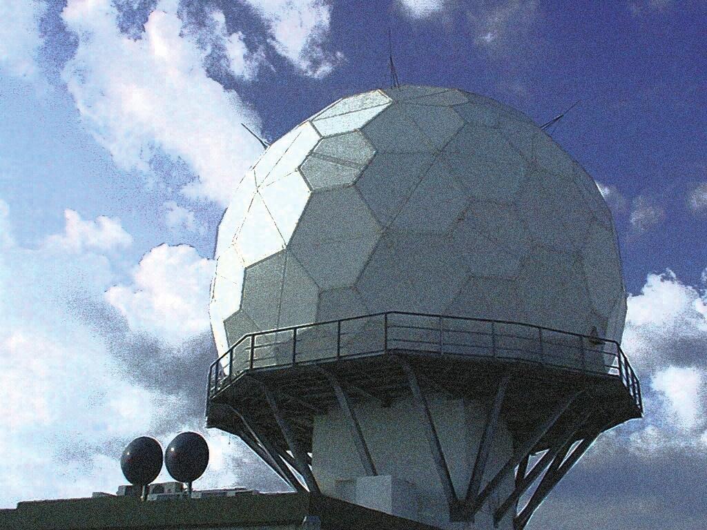
3 1. rass-m introduction RASS-M (Radar Analysis Support System for Maintenance activities) is intended for use by radar technicians during periodic check-ups of the radar under test (Primary or Secondary Surveillance Radar). RASS-M was developed completely independently from any radar manufacturer in order to offer you an all-round radar maintenance tool. The evaluation of the radar system will be completed quickly and with little interference to the controllers since the RASS-M system can be connected to signals which are already available and this under operational conditions. The RASS-M toolbox is a collection of the RASS-M software tools. A simple click on a measurement icon (button) will open up the tool of interest. In the toolbox the different software modules are arranged per hardware device and are listed in the same conceptual idea as in the RASS-S toolbox: top-down approach following the radar chain. The RASS-M toolbox is divided in 2 sections: Recording and Analysis. RASS-M stands for simplicity, stability and maintainability: Simplicity: The RASS-M software consists of the minimum number of tools to perform a measurement campaign. The RASS-M user interface is similar to that of RASS-S. The simplicity of the RASS-M hardware lies in the design of the new product line which consists of several small boxes with a similar layout (the same connectors are located in the same place on the different equipment) which are interconnected through a RASS Bus (RB) which contains the common timing signals. Stability: The RASS-M software is a simplified version of RASS-S and is a very stable software platform, that will require a minimum of updates. This makes it ideal for use with the compact RASS-M equipment and reduces the maintenance required by the limited software update cycle. Maintainability: The RASS-M software suit is based upon stand-alone tools that operate independently, allowing maintenance to be conducted on only the necessary components. The new RASS-M hardware kit consists of several lightweight, small boxes which are much smaller and lighter than the RASS-S hardware. The different RASS-M devices can be linked together through the RB (RASS Bus) connectors located on the rear of the devices. The RB provides several signals (radar timing signals, GPS data and power) that are common to the different devices. The RB concept simplifies the connection of the equipment to the radar and reduces the chance of connection errors. The Recording section includes all the recording tools of the RASS-M hardware, there is no need for a software license for the recording tools as the price of each recording tool is included in the corresponding hardware recording device. The Analysis section includes all the tools to view and analyse the RASS-M recorded data. A software license for these Analysis tools can be purchased separately. The customer can also decide not to purchase the Analysis license but to analyse the RASS-M recordings on a RASS-S workstation. The equipment on the following pages is part of the full RASS-M hardware kit. The radar technician uses RASS-M during the recurring maintenance activities to collect data and analyse the data on a basic level. If issues are found a RASS-S expert can analyse the data more thoroughly either on site or at his desk using the RASS-M Analysis package or RASS-S, as the RASS-M recorded data is fully compatible with RASS-S. The RASS-M suite has the option to be upgraded to RASS-S. Each customer can select the RASS-M configuration that best suits the maintenance needs. The full RASS-M configuration (5 devices) is delivered in a single protective pelicase and includes all the necessary accessories to use the devices in the field or on a radar site. The RASS-M workstation is delivered with a carrying bag. If the customer purchases a smaller configuration (for example to perform only antenna and gyro measurements), the items will be delivered in a trolley which can include up to 3 devices (and accessories) and the RASS-M workstation. The trolley is airline carryon friendly (be sure to check with your airline before traveling).. 4 5
SSR ATC radars and primary radars in L- and S-band.")

 Extracted HPD curve 2.1.")

4 1. 2.xrass-m hardware 2.1 Digital RF Analyser DRFA912 The Digital Rf Analyser or DRFA912 is intended for on-site performance checks of antennas and receivers of (M)SSR ATC radars and primary radars in L- and S-band. The RASS-M Extract HPD tool (part of the licensed RASS-M Analysis package) shows the pulses as they were recorded in time. Immediately you can recognize the boresights of one or more radars in such a diagram. By selecting a set of pulses and defining their stagger timing, the user can extract the fingerprint of the specific radar under test. After this fingerprinting the software will deal with extracting the different HPD curves from the recorded pulses. Stagger pattern (fingerprint of radar) Extracted HPD curve Antenna Measurements In the field the DRFA912 receives the RF signal under test and outputs digital data on the USB output port. For this purpose, the radar does not have to be taken out of its operational mode. The DRFA912 allows the user to perform Uplink recordings to evaluate the transmission antenna diagram, these recordings can be analysed with RASS-M tools or converted to RASS-S files for further analysis. The uplink recording function of the DRFA912 performs pulse detection and extracts timestamp, amplitude and pulse width of the recorded pulses.. 6 Uplink measurement result The OTD (Out of Tolerance Detection) function of the Extract HPD software will check important parameters against the EUROCONTROL standards for radar performance giving a detailed evaluation of the HPD diagram of your radar (3dB beam width, crossovers, punch-throughs (P1 > P2 outside the boresight region), 1st side lobe level,etc...). OTD parameters 7
 Receiver alignment (SUM, DELTA, SLS) for monopulse SSR systems Receiver bandwidth To perform a Bandwidth Calibration measurement, a test pulse with fixed or varying amplitude is used as")
5 2.1.2 Receiver Measurements The DRFA912 supports to measure the characteristics of the (M)SSR or PSR receiver channels, in order to investigate: RF receiver dynamic range Noise level measurement (sensitivity) Receiver alignment (SUM, DELTA, SLS) for monopulse SSR systems Receiver bandwidth To perform a Bandwidth Calibration measurement, a test pulse with fixed or varying amplitude is used as RF source. For this measurement the frequency of the test pulse is varied and the response voltage measured. Again the three monopulse channels can be checked successively and displayed in overlay to check the channels on alignment. Bandwidth Calibration For these measurements a signal generator injects RF power at the receiver input while the DRFA912 measures the resulting output voltage at the log receiver video output. To perform a Receiver Calibration measurement, RF pulses, generated at a selectable delay after the interrogation trigger and a selectable pulse width, are injected in the radar receiver. The power level of the RF pulses is decreased from a selectable maximum (up to +10dBm) in order to measure the receiver range going from saturation level down to the receiver s noise fl oor. For (M)SSR radar the three monopulse channels can be measured separately and displayed in overlay to check for channel alignment. For these systems the SUM and DELTA channels should typically perfectly align while the SLS channel typically differs. Receiver Calibration 8 9
 Technical Specifications Sample frequency 4 / 8 / 16 / 32 / 64MHz ADC resolution 14bit Triggering External / Analog / Ext pre-trigger / Ext delay / An pre-trigger /")

6 Interfaces-External Connectors Video 1/2 2x MCX Video input Rf CH1/CH2/Out SMA female RB1/2 2x DB15HD female Timing Signals and Power GPS DB9 female - GPS interface for timestamping USB USB2.0 B female (480Mbit/s high speed) Technical Specifications Sample frequency 4 / 8 / 16 / 32 / 64MHz ADC resolution 14bit Triggering External / Analog / Ext pre-trigger / Ext delay / An pre-trigger / An delay Video 1/2-2V...+2V, 1.1kΩ 3dB BW=32MHz Rf CH1/CH2 inputs Impedance 50Ω Frequency range MHz Demodulating 10.7MHz VSWR 1.15<2GHz / 1.3<4.5GHz Input power -13dBm Absolute maximum +20dBm Rf output Impedance 50Ω Frequency range MHz Max. output power <-5dBm RASS Bus: RB1/2 Timing signals TTL, 2kΩ Power in/out 400mA, 15V Connects to power supply or other RASS-M device General Specifications Power supply Through RASS Bus (via other RASS-M device) or directly via RB Power Supply Dimensions WxHxD (mm) 125x48x245 Weight 1.1kg Operating temperature 0 C C


7 1. 2.2x USB Video Recorder UVR892 Window-based Video recording: A UVR892 window-based video recording visualizes the transponder video data in great detail, along with all important side effects of the data, such as reflections, noise, FRUIT etc. Sectorial Video recording: The Sectorial Video Recorder is based on the UVR892 hardware and has been designed to create highly detailed video recordings, unlimited in both range as azimuth. The window width depends on the processing power of the PC. High-end desktops and laptops are able to record the full 360. The View Video tool (part of the licensed RASS-M Analysis package) allows you to review and investigate both window-based as sectorial video recordings. The USB Video Recorder or UVR892 digitizes the video signals of the radar. ACP/ARP generated by the antenna encoder and a trigger signal are passed to the UVR892 through the RB connection (after signal conditioning by the RTI966) so that the video signals are aligned with the appropriate timing. In RASS-M the UVR892 is used as a downlink and solar recording device: Downlink recording: The UVR892 enables the user to measure the HPD antenna pattern at reception of any (M)SSR or PSR antenna. It samples the video level signals of the input channels. The measured amplitudes are then converted to the received RF power at coupler level. To view the measured antenna diagrams, RASS-M contains a universal tool, called View HPD. The program is capable of reading, recognizing and displaying Uplink and Downlink HPD logfiles of both (M)SSR and PSR measurements. Solar recording: The UVR892 samples the noise of the sun (sun-strobe) and stores the information together with its azimuth and elevation position. By using astronomical algorithms, the solar elevation is calculated and used to build the VPD (Vertical Polar Diagram, db versus elevation) of the operational PSR. Another routine calculates the corresponding coverage diagram. The solar measurement is used as a sensitivity check-up of the complete radar system including the antenna chain. The RASS-M View VPD program (part of the licensed RASS-M Analysis package) is capable of reading and displaying PSR VPD Solar Logfiles recorded with the RASS-M hardware. It is possible to overlay antenna diagrams for comparison in up to five layers. Downlink measurement result Solar recording Video window recording 12 13


 ADC Resolution 12 bit RASS Bus: RB1/2 Timing")

8 Sector window recording Interfaces-External Connectors Ch 1/2 2x BNC - Video input RB1/2 2x DB15HD female Timing Signals and Power GPS DB9 female - GPS interface for timestamping USB USB2.0 B female (480Mbit/s high speed) Technical Specifications 2 video channels Analog input voltage -2V...+2V, 1kΩ Sampling rate 8MHz (2 channels)/16mhz (1 channel) ADC Resolution 12 bit RASS Bus: RB1/2 Timing signals TTL, 2kΩ Power in/out 300mA, 15V Connects to power supply or other RASS-M device General Specifications Dimensions WxHxD (mm) 125x48x245 Weight 1.1kg Operating temperature 0 C C. 14


9 2.3 Radar Timing Interface RTI966 ACP/ARP generated by the antenna encoder and a trigger signal are connected to the Radar Timing Interface or RTI966. The RTI966 provides the timing signals on the RB, available for all other RASS-M devices. A simple software configuration tool will allow the user to select between single ended or differential input signal and set the threshold level for ACP, ARP, trigger and OBI. RTI Configuration tool Interfaces-External Connectors In/Out DB9 male Differential Timing input In DB15HD female Single Ended Timing input RB1/2 2x DB15HD female Timing Signals and Power GPS DB9 female - GPS interface for timestamping USB USB2.0 B female (480Mbit/s high speed) Technical Specifications Differential Timing Input RS422/RS232 4 inputs or 4 outputs or 2 in- and 2 outputs Single Ended Timing Input Volt, 2kΩ Selectable trigger level, 4 inputs RASS Bus:RB1/2 Timing signals TTL, 2kΩ Power in/out 200mA, 15V Dimensions WxHxD (mm) 125x48x245 Weight 1.1kg Operating temperature 0 C C Connects to power supply or other RASS-M device General Specifications 16 17

 antenna and the data is logged in the RGI1193 s internal memory.")

10 2.4 Radar Gyroscope and Inclinometer RGI1193 Interfaces-External Connectors The Radar Gyroscope-and-Inclinometer (RGI1193) and the Radar Timing Interface (RTI966) allow you to evaluate the mechanical and structural design of the antenna support and tower under windloads, temperature, etc. The RGI1193 basically has 2 co-related functions, measuring: the quality of the encoder system the levelling of the platform The RGI1193 measures the angular velocity and planar angle of the antenna. For this purpose the device is mounted on the rotating part of the (SSR or PSR) antenna and the data is logged in the RGI1193 s internal memory. Meanwhile the RTI966 will record the ACP/ARP timing signals of the encoder under test.the rotational information data combined with the encoder signal provide essential information on encoder accuracy and platform leveling. Note that deviation on the instantaneous azimuth (= encoder error) is measured, because biases (e.g. wind-load) are simultaneously recorded at encoder and antenna level. These two signals plus their difference are shown in the software. Antenna start-up and stop are also recorded and provide information about the mechanical stiffness of the radar tower. The analysis program allows the user to view the recorded gyro and ACP measurements on a scan by scan basis over multiple revolutions. USB connector (Data and charging) Charge LED Recording LED WiFi antenna (RP-SMA) Technical Specifications Gyro Module Max. Angular Rate Resolution Configurable; ±-60 /s, ±120 /s, ±240 /s, ±720 /s 16-bit Self calibrated using radars North and time reference Inclino Module Measuring Range ±15 Sensitivity 0.01 Battery Battery Type Capacity Li-on Nominal Voltage 3.6V 2350mAh Watt-hour rating Weight 8Wh (acc. To UN38.3) 43g Built in Safety Unit (over voltage, under voltage, current limit) System runtime WiFi disabled System runtime WiFi enabled 15 hours 10 hours WiFi Type Mode Output Power bgn Access Point 17dBm Recording Sample Rate Configurable up to 1000Hz, default 200Hz Gyro-inclino Analysis software 18 Time 10 hours (at 200Hz) General Specifications Charge Temperature 10 C to 45 C Operating Temperature -20 C to 60 C Storage Temperature -40 C to 85 C Size 120x120x90 mm Weight 1240g 19

 and can operate on L/S/C/X band.")

11 2.5 USB Power Meter UPM772 Interfaces-External Connectors RF in connector SMA female Video Out connector BNC USB2.0 connector Technical Specifications RF Input Frequency Range 10MHz..10GHz Input Range typically dBm Maximum CW input power +12dBm Maximum peak input power +30dBm (2μs) Dynamic range 60dB for 10MHz to 6GHz Application range view calibration file Video Output The UPM772 is a broadband log receiver (10MHz to 10GHz) and can operate on L/S/C/X band. In the field of radar the UPM772 can be used as a pulse power meter designed for on site power measurements of the Tx and Tx driver of the radar under test. The UPM772 offers the following key features: Measure and record amplitude, shape and timing of radar pulses from SSR or PSR radars Visualisation of basic Tx power and pulse parameters such as: pulse width rise time fall time timed-sidelobes V Video Bandwidth 50MHz Rise time/fall time <20ns Transfer function Logarithmic Extra Specifications 8 bit ADC 15MHz sample rate General Specifications Power supply Through USB2.0 interface Dimensions WxHxD (mm) 135x80x30 Weight 0.2kg Charge Temperature -20 C C USB Power Meter software Output voltage 21


12 Intersoft Electronics Lammerdries-Oost Olen, Belgium Intersoft Electronics China Inventive Electronics Inc. US Office IE Asia-Pacific Pty Ltd Asia Pacific Office 23


13 IE-CD RASS-M
radar target generator RTG
 radar target generator RTG Rf target injection for primary radar The RTG (Radar Target Generator) is part of the RASS-S test equipment suite and is designed to generate primary radar returns. It can be
Radar Gyroscope and Inclinometer - RGI59x
 User Manual Edition: 003 Date: 11-Dec-12 Status: Released Issue DOCUMENT CHARACTERISTICS General User Manual Edition: 003 Edition Date: 11-December-2012 Status: Released Issue Keywords: User manual, RGI59x,
Didactical Test Interrogator - DTI529
 RASS-S Tutorial Edition: 1 Date: 03-Jan-13 Status: Draft Issue DOCUMENT CHARACTERISTICS General RASS-S Tutorial Edition: 1 Edition Date: 03-January-2013 Status: Draft Issue Keywords: User manual, DTI529,
ADS-B 1090ES Extraction
 User Manual Edition: 004 Date: 16-Aug-16 Status: Released Issue DOCUMENT CHARACTERISTICS General User Manual Edition: 004 Edition Date: 16-August-2016 Status: Released Issue Keywords: ADS-B, 1090ES, ARF800,
Reducing Test Flights Using Simulated Targets and a Carefully Chosen Set-up
 Reducing Test Flights Using Simulated Targets and a Carefully Chosen Set-up Edition: 001 Date: 18-FEB-09 Status: Released DOCUMENT DESCRIPTION Document Title Reducing Test Flights: Using Simulated Targets
S5101 Handheld Radio Communication Analyzer
 is the ideal radio tester for laboratory, production, service and maintenance use. It combines radio frequency emission, reception analysis, audio source, analyzer, etc. all into one unit. It can measure
radar performance evaluation
 radar performance evaluation A Performance Evaluation is a series of defined tests that subsequently provide a detailed analysis of the radar system at distinct levels: System Level (Level 1) This analysis
Reflectometer Series:
 Reflectometer Series: R54, R60 & R140 Vector Network Analyzers Clarke & Severn Electronics Ph +612 9482 1944 Email sales@clarke.com.au BUY NOW - www.cseonline.com.au KEY FEATURES Patent: US 9,291,657 No
Exercise 4. Angle Tracking Techniques EXERCISE OBJECTIVE
 Exercise 4 Angle Tracking Techniques EXERCISE OBJECTIVE When you have completed this exercise, you will be familiar with the principles of the following angle tracking techniques: lobe switching, conical
PROFESSIONAL RADIOFREQUENCY TECHNOLOGY SOLUTIONS
 PROFESSIONAL RADIOFREQUENCY TECHNOLOGY SOLUTIONS AIR TRAFFIC CONTROL BROADCASTING DEFENCE SCIENTIFIC INSTALLATIONS S RYMSA has been leading the market thanks to its RF technology products for more than
Modular Test Approaches for SSR Signal Analysis in IFF Applications
 Modular Test Approaches for SSR Signal Analysis in IFF Applications Military radar applications call for highly specialized test equipment Radar signal analysis applications require highly specialized
Vector Network Analyzers ZVB
 Specifications Version 05.00 Vector Network Analyzers ZVB September 2005 Specifications MEASUREMENT RANGE...3 MEASUREMENT SPEED...5 MEASUREMENT ACCURACY...6 EFFECTIVE SYSTEM DATA...8 TEST PORT OUTPUT...8
MTI Marker. User Manual. Edition: 4 Date: 07-Dec-15 Status: Released Issue
 User Manual Edition: 4 Date: 07-Dec-15 Status: Released Issue DOCUMENT CHARACTERISTICS General User Manual Edition: 4 Edition Date: 07-December-2015 Status: Released Issue Keywords: ; STG882; Static Target;
AIR ROUTE SURVEILLANCE 3D RADAR
 AIR TRAFFIC MANAGEMENT AIR ROUTE SURVEILLANCE 3D RADAR Supplying ATM systems around the world for more than 30 years indracompany.com ARSR-10D3 AIR ROUTE SURVEILLANCE 3D RADAR ARSR 3D & MSSR Antenna Medium
Model 745 Series. Berkeley Nucleonics Test, Measurement and Nuclear Instrumentation since Model 845-HP Datasheet BNC
 Model 845-HP Datasheet Model 745 Series Portable 20+ GHz Microwave Signal Generator High Power +23dBM Power Output 250 fs Digital Delay Generator BNC Berkeley Nucleonics Test, Measurement and Nuclear Instrumentation
Edition: Date: 29 May Main Report LEVEL 1 & 2 PERFORMANCE EVALUATION. NGSP S-Band PSR: DPR & (M)SSR: DTI529 - CBR
SSR: DTI529 - CBR") Edition: A Date: 29 May 2015 Status: Draft Main Report LEVEL 1 & 2 PERFORMANCE EVALUATION NGSP S-Band PSR: DPR & (M)SSR: DTI529 - CBR Level 1 & 2 Performance Evaluation Edition Date: 29 May 2015 Blank
Edition: A Date: 29 May 2015 Status: Draft Main Report LEVEL 1 & 2 PERFORMANCE EVALUATION NGSP S-Band PSR: DPR & (M)SSR: DTI529 - CBR Level 1 & 2 Performance Evaluation Edition Date: 29 May 2015 Blank
LB480A Pulse Profiling USB PowerSensor+ Data Sheet
 Key PowerSensor+ Specifications 100 MHz to 8 GHz (functional to 10 GHz) -60 dbm to +20 dbm 1.95% Total Error* 1.09:1 VSWR (-27 db Return Loss) * Measuring a well matched DUT (-20 dbm @ 1 GHz) Measurement
DSA800. No.1 RIGOL TECHNOLOGIES, INC.
 No.1 DSA800 9 khz to 1.5 GHz Frequency Range Typical -135 dbm Displayed Average Noise Level (DANL) -80 dbc/hz @10 khz offset Phase Noise Total Amplitude Uncertainty
PLANAR R54. Vector Reflectometer KEY FEATURES
 PLANAR R54 Vector Reflectometer KEY FEATURES Frequency range: 85 MHz 5.4 GHz Reflection coefficient magnitude and phase, cable loss, DTF Transmission coefficient magnitude when using two reflectometers
Spectrum Analyzers 2680 Series Features & benefits
 Data Sheet Features & benefits n Frequency range: 9 khz to 2.1 or 3.2 GHz n High Sensitivity -161 dbm/hz displayed average noise level (DANL) n Low phase noise of -98 dbc/hz @ 10 khz offset n Low level
Antenna Training and Measuring System
 Antenna Training and Measuring System LabVolt Series Datasheet Festo Didactic en 120 V - 60 Hz 05/2018 Table of Contents General Description 2 Antennas 5 Features & Benefits 7 List of Equipment 8 List
DSA700 Series Spectrum Analyzer
 DSA700 Series Spectrum Analyzer Product Features: All-Digital IF Technology Frequency Range from 100 khz up to 1 GHz Min. -155 dbm Displayed Average Noise Level (Typ.) Min.
Compact Series: S5065 & S5085 Vector Network Analyzers KEY FEATURES
 Compact Series: S5065 & S5085 Vector Network Analyzers KEY FEATURES Frequency range: 9 khz - 6.5 or 8.5 GHz Measured parameters: S11, S12, S21, S22 Wide output power adjustment range: -50 dbm to +5 dbm
Model 865 RF / Ultra Low Noise Microwave Signal Generator
 Model 865 RF / Ultra Low Noise Microwave Signal Generator Features Excellent signal purity: ultra-low phase noise and low spurious Combination of highest output power and fastest switching Powerful touch-display
R&S ZVT Vector Network Analyzer Specifications
 ZVT_dat-sw_en_0758-065-22_v0900_cover.indd Data Sheet 09.00 Test & Measurement R&S ZVT Vector Network Analyzer Specifications 06.03.205 5:50:4 CONTENTS Definitions... 3 Specifications... 4 Measurement
i-repeater Control and monitor all your repeaters through the cloud
 i-repeater Control and monitor all your repeaters through the cloud GSM, H+, 4G 800/900/1800/2100/2600Mhz Cloud control and monitoring Touch screen interface Diagrams SMA ports for internal antennas X4
LB480A Pulse Profiling USB PowerSensor+ Data Sheet
 Key PowerSensor+ Specifications 50 MHz to 8 GHz (functional to 10 GHz) - 60 dbm to +20 dbm 1.95% Total Error* 1.09:1 VSWR (-27 db Return Loss) * Measuring a well matched DUT (-20 dbm @ 1 GHz) No Zero No
Specification for Radiated susceptibility Test
 1 of 11 General Information on Radiated susceptibility test Supported frequency Range : 20MHz to 6GHz Supported Field strength : 30V/m at 3 meter distance 100V/m at 1 meter distance 2 of 11 Signal generator
MultiMaster. Base Station Test Tools. Multi Purpose Base Station Tester. Introduction. Feature
 Introduction The GenComm is a comprehensive and cost effective solution for performing base station and repeater maintenance in any environment covering all CDMA Standards including cdmaone, cdma2000 1x
Multifunctional Microwave Analyzer
 AV4958 (1MHz~20GHz) Multifunctional Microwave Analyzer Product Overview AV4958 Multifunctional Microwave Analyzer integrates multiple functions, such as tests of cable and antenna SWR, distance to fault(dtf),
LB679A CW and Pulse (Modulation) USB PowerSensor+ Data Sheet
 USB PowerSensor+ Data Sheet") Key PowerSensor+ Specifications 50 MHz to 20 GHz - 40 dbm to +20 dbm 2.8% Total Error* 1.20:1 VSWR (-21 db Return Loss) * Measuring a well matched DUT (-20 dbm @ 2 GHz) Key PowerSensor+ Capability Test
Key PowerSensor+ Specifications 50 MHz to 20 GHz - 40 dbm to +20 dbm 2.8% Total Error* 1.20:1 VSWR (-21 db Return Loss) * Measuring a well matched DUT (-20 dbm @ 2 GHz) Key PowerSensor+ Capability Test
FREQUENCY SYNTHESIZERS, SIGNAL GENERATORS
 SYNTHESIZED SIGNAL GENERATOR MG3641A/MG3642A 12 khz to 1040/2080 MHz NEW New Anritsu synthesizer technology permits frequency to be set with a resolution of 0.01 Hz across the full frequency range. And
INSTRUCTION SHEET WIDEBAND POWER SENSOR MODEL Copyright 2008 by Bird Electronic Corporation Instruction Book P/N Rev.
 INSTRUCTION SHEET WIDEBAND POWER SENSOR MODEL 5012 Copyright 2008 by Bird Electronic Corporation Instruction Book P/N 920-5012 Rev. C Description The Bird 5012 Wideband Power Sensor (WPS) is a Thruline
GMES Sentinel-1 Transponder Development
 GMES Sentinel-1 Transponder Development Paul Snoeij Evert Attema Björn Rommen Nicolas Floury Malcolm Davidson ESA/ESTEC, European Space Agency, Noordwijk, The Netherlands Outline 1. GMES Sentinel-1 overview
LB680A Pulse Profiling USB PowerSensor+ Data Sheet
 Key PowerSensor+ Specifications 50 MHz to 20 GHz - 40 dbm to +20 dbm 2.8% Total Error* 1.20:1 VSWR (-21 db Return Loss) * Measuring a well matched DUT (-20 dbm @ 2 GHz) Measurement Capability Time Gated
2400C Series Microwave Signal Generators 10 MHz to 40 GHz. Preliminary Technical Datasheet. Low Phase Noise and Fast-Switching Speed in a Single Unit
 Preliminary Technical Datasheet 2400C Series Microwave Signal Generators 10 MHz to 40 GHz Low Phase Noise and Fast-Switching Speed in a Single Unit 2400C Series Microwave Signal Generator Signal Generator
Exercise 1-3. Radar Antennas EXERCISE OBJECTIVE DISCUSSION OUTLINE DISCUSSION OF FUNDAMENTALS. Antenna types
 Exercise 1-3 Radar Antennas EXERCISE OBJECTIVE When you have completed this exercise, you will be familiar with the role of the antenna in a radar system. You will also be familiar with the intrinsic characteristics
Model 745 Series. Berkeley Nucleonics Test, Measurement and Nuclear Instrumentation since Model 845-M Specification 1.8 BNC
 Specification 1.8 Model 745 Series 0.01-20.0 GHz Low Phase Noise Synthesizer 250 fs Digital Delay Generator Berkeley Nucleonics Test, Measurement and Nuclear Instrumentation since 1963 Introduction The
Agilent 8902A Measuring Receiver
 Agilent 8902A Measuring Receiver Technical Specifications Agilent 11722A Sensor Module Agilent 11792A Sensor Module Agilent 11793A Microwave Converter Agilent 11812A Verification Kit The Agilent Technologies
Agilent 8360B Series Synthesized Swept Signal Generators 8360L Series Synthesized Swept CW Generators Data Sheet
 Agilent 8360B Series Synthesized Swept Signal Generators 8360L Series Synthesized Swept CW Generators Data Sheet 10 MHz to 110 GHz Specifications apply after full user calibration, and in coupled attenuator
Technical Datasheet GT-8550B Series USB Power Sensor 10 MHz to 26.5 GHz
 Technical Datasheet GT-8550B Series USB Power Sensor 10 MHz to 26.5 GHz PC-based Power Meter 35424-Rev.A/ US122112 GT-8550B Series USB Power Sensors GT-8550B Series USB Peak Power Sensors Advanced Power
Agilent N9923A FieldFox RF Vector Network Analyzer 2 MHz to 4/6 GHz. Data Sheet
 Agilent N9923A FieldFox RF Vector Network Analyzer 2 MHz to 4/6 GHz Data Sheet Table of Contents Definitions... 2 FieldFox RF Vector Network Analyzer... 3 Cable and Antenna Analyzer (Option 305)... External
Monopulse Antenna. Figure 2: sectional picture of an antenna array of a monopulse antenna
 Monopulse Antenna Figure 1: Principle of monopulse antenna Figure 2: sectional picture of an antenna array of a monopulse antenna Under this concept antennae are combined which are built up as an antenna
R&S ZVT Vector Network Analyzer Specifications
 R&S ZVT Vector Network Analyzer Specifications Test & Measurement Data Sheet 08.00 CONTENTS Definitions... 3 Specifications... 4 Measurement range...4 Measurement speed...5 Measurement accuracy...6 Effective
Spectrum Analyzer R&S FS300
 Spectrum Analyzer R&S FS300 9 khz to 3 GHz The new product family from Rohde & Schwarz Professional test equipment for laboratory, service and production The R&S FS300 is a highly accurate spectrum analyzer
SIGNAL RECOVERY. Model 7265 DSP Lock-in Amplifier
 Model 7265 DSP Lock-in Amplifier FEATURES 0.001 Hz to 250 khz operation Voltage and current mode inputs Direct digital demodulation without down-conversion 10 µs to 100 ks output time constants Quartz
QuickSyn Frequency Synthesizers
 QuickSyn Frequency Synthesizers The QuickSyn Advantage Our popular line of QuickSyn frequency synthesizers delivers instrumentgrade performance up to 82 GHz, increased functionality, and efficient power
PLANAR 814/1. Vector Network Analyzer
 PLANAR 814/1 Vector Network Analyzer Frequency range: 100 khz 8 GHz Measured parameters: S11, S12, S21, S22 Wide output power range: -60 dbm to +10 dbm >150 db dynamic range (1 Hz IF bandwidth) Direct
R&S ZNC Vector Network Analyzer Specifications
 ZNC3_dat-sw_en_5214-5610-22_v0300_cover.indd 1 Data Sheet 03.00 Test & Measurement R&S ZNC Vector Network Analyzer Specifications 04.09.2012 13:39:47 CONTENTS Definitions... 3 Measurement range... 4 Measurement
Agilent N1911A/N1912A P-Series Power Meters and N1921A/N1922A Wideband Power Sensors. Data sheet
 Agilent N1911A/N191A P-Series Power Meters and N191A/N19A Wideband Power Sensors Data sheet Specification Definitions There are two types of product specifications: Warranted specifications are specifications
Keysight Technologies N9320B RF Spectrum Analyzer
 Keysight Technologies N9320B RF Spectrum Analyzer 9 khz to 3.0 GHz Data Sheet Definitions and Conditions The spectrum analyzer will meet its specifications when: It is within its calibration cycle It has
PLANAR S5048 and TR5048
 PLANAR S5048 and TR5048 Vector Network Analyzers KEY FEATURES Frequency range: 20 khz 4.8 GHz COM/DCOM compatible for LabView Measured parameters: and automation programming S11, S12, S21, S22 (S5048)
Agilent N9320B RF Spectrum Analyzer
 Agilent N9320B RF Spectrum Analyzer 9 khz to 3.0 GHz Data Sheet Definitions and Conditions The spectrum analyzer will meet its specifications when: It is within its calibration cycle It has been turned
Portable Multi-Channel Recorder Model DAS240-BAT
 Data Sheet Portable Multi-Channel Recorder The DAS240-BAT measures parameters commonly found in process applications including voltage, temperature, current, resistance, frequency and pulse. It includes
ER55 EMI TEST RECEIVER Family of automatic test receivers for measurement of electromagnetic interference from 9kHz to 1GHz
 ER55 EMI TEST RECEIVER Family of automatic test receivers for measurement of electromagnetic interference from 9kHz to 1GHz Compact designed and manufactured in compliance with CISPR 16-1, For Measurements
AV4958 Multifunctional Microwave Analyzer
 AV4958 Multifunctional Microwave Analyzer Product Overview AV4958 Multifunctional Microwave Analyzer integrates multiple functions like testing of cable and antenna VSWR, distance to fault(dtf), insertion
Product Overview. Main Characteristics. (9KHz~20GHz/26.5GHz/32GHz/44GHz)
") AV4024D/E/F/G Spectrum Analyzer (9KHz~20GHz/26.5GHz/32GHz/44GHz) Product Overview AV4024D/E/F/G Spectrum Analyzer possesses many advantages: a wide frequency range, high performance, high sweep speed,
AV4024D/E/F/G Spectrum Analyzer (9KHz~20GHz/26.5GHz/32GHz/44GHz) Product Overview AV4024D/E/F/G Spectrum Analyzer possesses many advantages: a wide frequency range, high performance, high sweep speed,
JD723A/JD724B/JD726A Cable and Antenna Analyzers
 COMMUNICATIONS TEST & MEASUREMENT SOLUTIONS JD723A/JD724B/JD726A Cable and Antenna Analyzers Key Features Portable and lightweight handheld instrument. Built in wireless frequency bands as well as the
DSA800. No.2 RIGOL TECHNOLOGIES, INC. All-Digital IF Technology 9 khz GHz Frequency Range
 No.2 DSA800 All-Digital IF Technology 9 khz - 1.5 GHz Frequency Range Up to -135dBm Displayed Average Noise Level (DANL) -80dBc/Hz @ 10kHz Oset Phase Noise Total Amplitude Uncertainty < 1.5dB 100Hz Minimum
Agilent 8920A RF Communications Test Set Product Overview
 Agilent 8920A RF Communications Test Set Product Overview Cut through problems faster! The Agilent Technologies 8920A RF communications test set was designed to solve your radio testing and troubleshooting
EXTEND YOUR REACH. Copper Mountain Technologies USB VNAs. S-parameter measurement solutions from 9 khz to 110 GHz Measured parameters from S 11
 Copper Mountain Technologies USB VNAs S-parameter measurement solutions from 9 khz to 110 GHz Measured parameters from S 11 to S 44 Dynamic range as high as 162 db typ. (1 Hz IF bandwidth) Measurement
Models 1421 and 1422 User s Manual. Broadband Amplifiers
 Models 1421 and 1422 User s Manual Broadband Amplifiers 142101 Rev. A 2 Is a registered trademark of New Focus, Inc. Warranty New Focus, Inc. guarantees its products to be free of defects for one year
Antenna Trainer EAN. Technical Teaching Equipment INTRODUCTION
 Antenna Trainer EAN Technical Teaching Equipment Products Products range Units 3.-Communications INTRODUCTION Antennas are the main element of aerial communications. They are the transition between a transmission
SIGNAL GENERATORS. MG3633A 10 khz to 2700 MHz SYNTHESIZED SIGNAL GENERATOR GPIB
 SYNTHESIZED SIGNAL GENERATOR MG3633A GPIB For Evaluating of Quasi-Microwaves and Measuring High-Performance Receivers The MG3633A has excellent resolution, switching speed, signal purity, and a high output
User s Manual. CONTROL STATION COMBINER Broad Band Short Haul MHz. Document Number: INS
 User s Manual CONTROL STATION COMBINER Broad Band Short Haul 40-960MHz Document Number: INS40976-1 Company Overview RFI has been serving the needs of the wireless communications market for over 30 years.
IZT T1000 Compact Broadcast Modulator
 www.izt-labs.de IZT T1000 Compact Broadcast Modulator Fully reconfigurable, software-defined modulator platform for DAB and DVB-T/DVB-T2 VHF and UHF (selectable frequency from 30 MHz to 860 MHz in steps
G7104A Multimaster Base Station Tester
 COMMUNICATIONS TEST & MEASUREMENT SOLUTIONS G7104A Multimaster Base Station Tester Key features Multi-function integration The Multimaster has integrated all necessary functions to test and measure CDMA
DRTS-6. DRTS-6 has been designed to test: DRTS-6. Advanced Protection Relay Test Set and Measurement System
 DRTS-6 Advanced Protection Relay Test Set and Measurement System MULTI-TASKING EQUIPMENT DESIGNED FOR TESTING PROTECTION RELAYS, ENERGY METERS, TRANSDUCERS POWERFUL AND LIGHTWEIGHT HIGH ACCURACY: BETTER
RASS-R product catalogue. RAdar data analysis and display systems
 RASS-R product catalogue RAdar data analysis and display systems Product range ie test equipment The Intersoft Electronics product range covers a wide spectrum of instruments supporting radar technicians
Simple Assessment Beauvechain wind-turbine mitigation
 IE-SAWM-EBBE-0021 BAF REF: 3D/XXXX Simple Assessment Beauvechain wind-turbine mitigation EDF Luminus - Herentals Edition: 001 Date: 14-Nov-17 Status: Released Issue DOCUMENT CHARACTERISTICS General Simple
TRANSCOM Manufacturing & Education. Transcom Instruments. Product Brochure TRANSCOM INSTRUMENTS. Product Brochure.
 TRANSCOM INSTRUMENTS Product Brochure Transcom Instruments Product Brochure www.transcomwireless.com 1 Vector Signal Generator Overview Vector Signal Generator is a high performance vector signal generator.
Quick Site Testing with the 8800SX
 Quick Site Testing with the 8800SX Site Testing with the 8800SX Basic Tests 5 site testing involves several tests to verify site operation. NOTE: This is not intended to be a complete commissioning procedure.
Thruline RF Directional Wattmeters
 Portable Wattmeters BIRD S Famous ANALOG METER MODEL 43 Portable Wattmeter Power Range 100 mw - 10 kw using Bird Plug-in Elements.* Insertion VSWR with N Connectors 1.05 max. to 1000 MHz Finish Light Gray
Advanced Test Equipment Rentals ATEC (2832)
") Established 1981 Advanced Test Equipment Rentals www.atecorp.com 800-404-ATEC (2832) EMI Testing According to CSPR Publication 16 Recommendations Combining the 85685A RF preselector with the 8566B or 8568B
Established 1981 Advanced Test Equipment Rentals www.atecorp.com 800-404-ATEC (2832) EMI Testing According to CSPR Publication 16 Recommendations Combining the 85685A RF preselector with the 8566B or 8568B
Series MICROWAVE LINKS DIGITAL & ANALOG - FIXED & MOBILE. The high quality, professional and cost-effective solution
 MICROWAVE LINKS DIGITAL & ANALOG - FIXED & MOBILE Series PM The high quality, professional and cost-effective solution In 1982 ABE Elettronica introduced The Microwave Link line which was immediately successful,
Impedance 50 (75 connectors via adapters)
") VECTOR NETWORK ANALYZER PLANAR 304/1 DATA SHEET Frequency range: 300 khz to 3.2 GHz Measured parameters: S11, S21, S12, S22 Dynamic range of transmission measurement magnitude: 135 db Measurement time
VECTOR NETWORK ANALYZER PLANAR 304/1 DATA SHEET Frequency range: 300 khz to 3.2 GHz Measured parameters: S11, S21, S12, S22 Dynamic range of transmission measurement magnitude: 135 db Measurement time
GPS Time and Frequency Reference Receiver
 $ GPS Time and Frequency Reference Receiver Symmetricom s 58540A GPS time and frequency reference receiver features: Eight-channel, parallel tracking GPS engine C/A Code, L1 Carrier GPS T-RAIM satellite
Analog signal generator that meets virtually every requirement
 GENERAL PURPOSE 44434/5 FIG 1 The R&S SMA1A offers excellent performance and compact design at a favorable price. Signal Generator R&S SMA1A Analog signal generator that meets virtually every requirement
WaveStation Function/Arbitrary Waveform Generators
 Function/Arbitrary Waveform Generators Key Features High performance with 14-bit waveform generation, up to 500 MS/s sample rate and up to 512 kpts memory 2 channels on all models Large color display for
Agilent CSA Spectrum Analyzer
 Agilent CSA Spectrum Analyzer N1996A Exceptional performance... anytime, anywhere Frequency coverage Frequency range: 100 khz to 3 or 6 GHz Signal source: 10 MHz to 3 or 6 GHz Preamplifier to 3 or 6 GHz
WaveStation Function/Arbitrary Waveform Generators
 WaveStation Function/Arbitrary Waveform Generators Key Features High performance with 14-bit, 125 MS/s and 16 kpts 2 channels on all models Large 3.5 color display for easy waveform preview Over 40 built-in
Compact Series: S5048 & TR5048 Vector Network Analyzers KEY FEATURES
 Compact Series: S5048 & TR5048 Vector Network Analyzers KEY FEATURES Frequency range: 20 khz - 4.8 GHz Measured parameters: S11, S12, S21, S22 (S5048) S11, S21 (TR5048) Wide output power adjustment range:
Spectrum Analyzers U3771/3772. Handling frequencies of up to 43 GHz!! Our new microwave spectrum analyzer, ideal for field use, is now available.
 Spectrum Analyzers U3771/3772 Handling frequencies of up to 43 GHz!! Our new microwave spectrum analyzer, ideal for field use, is now available. A New Standard for Microwave and Millimeter-wave Spectrum
GT 9000 GT 9000S MICROWAVE
 Page 1 of 6 GT 9000 GT 9000S MICROWAVE Now you can get the performance you need and the capability you want, at a price you can afford. Both the Giga-tronics GT9000 Microwave Synthe- techniques.together,
2801 Multilock. Communications System Analyzer. Data Sheet. Boosting wireless efficiency
 Data Sheet 2801 Multilock Communications System Analyzer Boosting wireless efficiency A real multi-talented instrument the Willtek 2801 Multilock The Willtek 2801 Multilock is a test instrument for multiple
Exercise 1-5. Antennas in EW: Sidelobe Jamming and Space Discrimination EXERCISE OBJECTIVE
 Exercise 1-5 Antennas in EW: Sidelobe Jamming EXERCISE OBJECTIVE To demonstrate that noise jamming can be injected into a radar receiver via the sidelobes of the radar antenna. To outline the effects of
FieldFox Handheld Education Series Part 7: Precision Validation of Radar System Performance in the Field
 FieldFox Handheld Education Series Part 7: Precision Validation of Radar System Performance in the Field FieldFox Handheld Education Series Interference Testing Cable and Antenna Measurements Calibration
Precision Validation of Radar System Performance in the Field
 Precision Validation of Radar System Performance in the Field August 19, 2015 Tom Hoppin Application Specialist Component Test Division Keysight Technologies Keysight Technologies 2015 1 Precision Validation
PRODUCT CATALOG. RF Test. VIAVI Solutions. Antennas
 PRODUCT CATALOG RF Test VIAVI Solutions Antennas Table of Contents Selection Table...2 Omni Antenna G700050353, G700050354, G700050355, G700050356, G700050357...3 Dual Band Omni Antenna G700050359... 5
Superior Radar Imagery, Target Detection and Tracking SIGMA S6 RADAR PROCESSOR
 Superior Radar Imagery, Target Detection and Tracking SIGMA S6 S TA N D A R D F E AT U R E S SIGMA S6 Airport Surface Movement Radar Conventional Radar Image of Sigma S6 Ice Navigator Image of Radar Inputs
Dual Channel Function/Arbitrary Waveform Generators 4050 Series
 Data Sheet Dual Channel Function/Arbitrary Waveform Generators The Dual Channel Function/Arbitrary Waveform Generators are capable of generating stable and precise sine, square, triangle, pulse, and arbitrary
CAA-100A Cable & Antenna Analyzer + Spectrum Analyzer
 CAA-100A Cable & Antenna Analyzer + Spectrum Analyzer ShinewayTech CAA-100A cable & antenna analyzer with spectrum analyzer can test DTF/Frequency Return Loss, VSWR, Cable Loss, RF Power and Spectrum.
HMC-T2220B. Portable & Battery Operated! Portable Synthesized Signal Generator, 10 MHz to 20 GHz. Instrumentation Product Support at
 Portable, 10 MHz to 20 GHz Portable & Battery Operated! 78-250-3343 tel 78-250-3373 fax Battery Operated 20 GHz Signal Generator! The is a battery powered, portable test equipment solution designed to
MODELS WW5061/2. 50MS/s Single/Dual Channel Arbitrary Waveform Generators
 Single / Dual Channel 50MS/s waveform generator Sine waves to 25MHz, Square to 15MHz SINE OUT to 50MHz, 1Vp-p 11 Built-in popular standard waveforms 14 Bit amplitude resolution 11 digits frequency resolution
Product Overview: Main Features: AV3672A/B/C -S Vector Network Analyzer. (10MHz~13.5 GHz/26.5 GHz/43.5 GHz)
") AV3672A/B/C -S Vector Network Analyzer (10MHz~13.5 GHz/26.5 GHz/43.5 GHz) Product Overview: AV3672*-S series vector network analyzer is consist of AV3672A-S(10MHz~13.5GHz), AV3672B-S(10MHz~26.5GHz)and
AV3672A/B/C -S Vector Network Analyzer (10MHz~13.5 GHz/26.5 GHz/43.5 GHz) Product Overview: AV3672*-S series vector network analyzer is consist of AV3672A-S(10MHz~13.5GHz), AV3672B-S(10MHz~26.5GHz)and
Agilent 83711B and 83712B Synthesized CW Generators
 View at www.testequipmentdepot.com Agilent 83711B and 83712B Synthesized CW Generators Agilent 83731B and 83732B Synthesized Signal Generators Data Sheet 10 MHz to 20 GHz 1 to 20 GHz Specifications describe
Agilent 8560 EC Series Spectrum Analyzers Data Sheet
 Agilent 8560 EC Series Spectrum Analyzers Data Sheet Agilent 8560EC 30 Hz to 2.9 GHz Agilent 8561EC 30 Hz to 6.5 GHz 1 Agilent 8562EC 30 Hz to 13.2 GHz Agilent 8563EC 30 Hz to 26.5 GHz Agilent 8564EC 30
Model 855 RF / Microwave Signal Generator
 Features Very low phase noise Fast switching Phase coherent switching option 2 to 8 phase coherent outputs USB, LAN, GPIB interfaces Applications Radar simulation Quantum computing High volume automated
A DUAL-RECEIVER METHOD FOR SIMULTANEOUS MEASUREMENTS OF RADOME TRANSMISSION EFFICIENCY AND BEAM DEFLECTION
 A DUAL-RECEIVER METHOD FOR SIMULTANEOUS MEASUREMENTS OF RADOME TRANSMISSION EFFICIENCY AND BEAM DEFLECTION Robert Luna MI Technologies, 4500 River Green Parkway, Suite 200 Duluth, GA 30096 rluna@mi-technologies.com
Dual Channel Function/Arbitrary Waveform Generators 4050 Series
 Data Sheet Dual Channel Function/Arbitrary Waveform Generators The Dual Channel Function/Arbitrary Waveform Generators are capable of generating stable and precise sine, square, triangle, pulse, and arbitrary