G series. AC Servo Drive. User s Manual (V1.6), applicable to drives of software version 1.19 or above
|
|
|
- Ada Hoover
- 5 years ago
- Views:
Transcription
1 G series User s Manual 2016 (V1.6), applicable to drives of software version 1.19 or above Applicable type:all types of G-B and G2A3204 G2A3208 1
2 Safety Precautions Before product storage, installation, wiring, operation, check or maintenance, users must be familiar with and observe the following important notes to ensure safety during use of the product. 1 ELECTRIC SHOCK INJURY WARNING Warning When the driver is powered on, do not open the housing of the machine for fear of electric shock. When the housing is open, do not power on the driver for fear of touching any exposed high-voltage part. In maintenance of the driver, wait for at lest five minutes after cutting off the power, and detect both ends of the high-voltage capacitor using a voltmeter. The maintaining operation is allowed only when it is confirmed that the safe voltage range is reached. Power on only after reliable installation of the driver. Servo driver and servo motor must be reliably grounded. Do not touch the driver with wet hands for fear of electric shock. Wrong voltage or power supply polarity may cause an explosion or operational accidents. Ensure that the wire is properly insulated to avoid squeezing the wire and electric shock. 2 WARNING OF DAMAGE TO EQUIPMENT Warning Do not directly connect power to the U, V or W output ends of the driver for fear of damaging the driver. The servo motor and servo driver should be directly connected. Do not connect the U, V or W output ends of the driver to any capacitive element (e.g. noise suppression filter, pulse interference limiter, etc.) for fear of improper work of the driver. Connect the input end of the driver to a compliant power supply as required. Please verify the correctness and reliability of the cable connections before energizing. Please purchase and use motor as required, or damage to the driver or motor may occur. The rated torque of the servo motor should be higher than the effective continuous load torque. The ratio between the load inertia and servo motor inertia should be less than the recommended value. 2
3 3 FIRE WARNING Warning The driver should not be installed on the surface of a combustible and should be kept away from flammable materials. Otherwise, a fire accident may occur. Do not use it at a place which is damp, full of corrosive gas or flammable gas for fear of a fire. When any abnormal situation occurs while the driver operates, please immediately cut off the power for repair. Long-time overloaded operation of the driver may cause damage and fire. 4 ENVIRONMENTAL REQUIREMENTS Warning Parameter Conditions Humidity 90% (no condensation) Operating temperature 0 to +40 (non-condensing) Storage temperature -40 ~ +55 С Elevation Less than sea level 1,000m Vibration Air environment Less than 0.5G (4.9m/s 2 ) 10-60HZ (non-continuous operation) No corrosive, flammable gas or oil mist 3
4 Contents Chapter I Product Inspection and Installation Product Inspection Description of Servo Drive Model Servo Drive Model Installation of servo driver Installation environment conditions Installation method Mounting dimensions Attention in Installation Installation of servo motor Installation method Installation precautions Determination of motor rotation direction...10 Chapter II Wiring Wiring Instructions and Precautions Descriptions of Terminals Communication and connection terminal Function IO of CN2 terminal Motor encoder terminal CN Configuration of CN1 terminal CN1 functional descriptions Input/output Interface Types Type1 switch input interface Type2 switch input interface Type3 pulse input interface Type4 analog input interface Type5 encoder signal output interface Type6 encoder Z phase signal open-collector output interface Type7 input interface of photoelectric encoder of servo motor Connection Requirements Standard Wiring Diagram Wiring of Main Circuit G-B Series Wiring diagram of position mode G-B Series Wiring diagram of speed / torque mode G2 Series Wiring diagram of position mode G-B Series Wiring diagram of speed/torque mode...26 Chapter III Panel Operation Drive Panel Panel composition Function switching Parameter (Pn-xx) Operations Monitor/Display (Fn-xx) Operation Operation of Historical Fault Display (En-xx) Operation of Auxiliary Function (dn-xx) Brake Release Test
5 3.5.2 JOG Operation Drive initialization Drive resetting...32 Chapter IV Parameters Summary of Parameters Parameter Details Details of P0 segment parameters Details of P1 segment parameters Details of P2 segment parameters Details of P3 segment Details of P4 segment parameters Details of P5 segment parameters...50 Chapter V Operation Working Sequence Power-on sequences Timing diagram NOTES Check before Operation Position control mode Wiring Operations Setting of Electronic gear Gain adjustment Overtravel limit Speed control mode Analog input speed mode Internal speed control JOG operation Torque Control Mode...63 Chapter VI Communication Function Communication Overview Overview of Communication Parameters MODBUS Communication Protocol Code meaning Character structure Communication data structure Chapter VII Product Warranty and Maintenance...71 Appendix A Performance Indicators...72 Appendix B Definition of Motor Plug...73 Appendix C Motor Configuration Sheet MG series motors HD series motors DY series motors YH series motors SEW series motors...79 Appendix D Alarms


6 Chapter I Product Inspection and Installation 1.1 Product Inspection The product has been subject to the complete functional test before delivery. In order to prevent the product from anomaly caused by negligence in transportation, please carefully check the following items after unpacking. 1. Check whether the models of the servo drive and servo motor are the same as the ordered model. 2. Check whether the servo drive and servo motor are damaged and scratched. If damage is caused during transportation, wiring and power supply will be prohibited: 3. Check whether any component of the servo drive and servo motor is loose and whether any screw is loose or unlocked or falls off; 4. Check whether the rotor shaft of the servo motor can be rotated smoothly in a manual manner. The motor with brake cannot be rotated directly. Immediately contact the dealer in case of any failure or anomaly of the above items. 1.2 Description of Servo Drive Model (1)Naming of G-B series servo drives: (2)Naming of G2 series servo drives: 1.3 Servo Drive Model 1.4 Installation of servo driver Installation environment conditions The installation environment of the servo drive has direct effects on the normal functions and service life and thus must meet the following conditions. 1. Operation temperature: 0-40 ; operation humidity: below 40% to 80% (non-condensing). Storage temperature: -40 to 50 ; storage humidity: below 93% (non-condensing). 6
7 2. Vibration: below 0.5G. 3. Prevent rain or moisture. 4. Prevent direct exposure to sunlight. 5. Prevent erosion of oil mist and salt and intrusion of corrosive liquid, gas, dust, cotton fibers and metal chippings. 6. Keep the product away from radioactive materials and combustibles. 7. If several drives are installed in the control cabinet, pay attention to the locations and reserve sufficient space to facilitate air circulation and heat dissipation. Install a cooling fan to reduce the ambient temperature of the servo drive. The working temperature should be below 40 for long-time safe operation. 8. If the vibration source (such as punch) nearby is inevitable, please use the vibration absorber or anti-vibration rubber gasket; 9. The interference equipment nearby may cause misoperation of the servo drive due to interference to the power line and control line. Anti-interference measures such as the noise filter can be adopted to ensure normal operation of the drive. However, the leakage current will be increased by the noise filter, and an isolation transformer should be installed at the power input end of the drive Installation method The servo drive should be installed in the vertical direction, with the top upward to facilitate heat dissipation. Tighten M5 fixing screws on the back of the servo drive during installation. Refer to the figure for the installation spacing between servo drives and also between the servo drive and other equipment. In order to guarantee the performance and life of the drive, please reserve sufficient installation spacing as possible as practical. The cooling fan must be installed in the electrical control cabinet to cool the radiator of the servo drive with air flow in the vertical direction. The servo drive must be prevented from dust or iron chippings during installation of the electrical control cabinet Mounting dimensions (1)The installation and fixing dimension of G-B series are as follows: Figure 1-1 Dimension of G-B series G-B 通用型 A(mm) B(mm) C(mm) D(mm) E(mm) GA3207B GA3210 B GA3215 B GA3230 B (2) The installation and fixing dimension of G2 series are as follows: 7
 Stabilization The four screws at the back of the driver should be tightened.")
8 G2-750W is shown in the following figure: Figure 1-2 The dimension of G2-400W Attention in Installation Figure 1-3 The dimension of G2-7500W (1) Stabilization The four screws at the back of the driver should be tightened. (2) Installation clearance Required clearance between the driver and control cabinet box and between other electronic equipment should be left. Minimum clearance requirements are shown in Figure 1-4. (3) Ventilation and heat dissipation If more than one driver needs to be provided, the cooling requirements for each of them should be taken into account. Cooling fan should be provided in the electrical control cabinet, ensuring that there is wind to cool the driver at the vertical direction. The minimum clearance requirements for this purpose are shown in Figure


9 Figure 1-4 Minimum Installation Clearance Requirements Figure 1-5 Minimal Installation Clearance and Cooling Requirements for Multiple Drivers 1.5 Installation of servo motor Installation method Horizontal installation: To avoid water, oil or liquid from flowing into the port of motor line, the cable outlet should be provided at the bottom Vertical Installation: If the motor shaft is provided upward and a reducer is equipped, measures to prevent grease of the reducer from entering into the motor via the motor shaft Installation precautions 1. When the pulley is installed and removed, the motor or motor shaft must not be knocked with a hammer to prevent damage to the motor bearing and encoder. Instead, the pulley should be removed with the spiral pulling tool. 2. The motor shaft should have sufficient extension; otherwise, the motor may vibrate during operation. 3. Use loose washer to fasten the motor. 4. Do not apply excessive axial or radial force against the motor. A flexible coupling is recommended for the connection. 9
10 1.6 Determination of motor rotation direction In this manual, the motor rotation direction is defined as follows: when you face the stretched part of the motor shaft, if the rotation axis rotates counterclockwise, it is called positive rotation; otherwise, it is negative rotation. See Figure 1-6. CCW (counterclockwise) Figure 1-6 Rotation Direction of Motor CW (clockwise) 10

11 Chapter II Wiring 2.1 Wiring Instructions and Precautions 1. Wiring materials should meet the wire specifications; 2. The command cable should be less than 3m long, and the encoder cable should be less than 20m long; 3. Check whether the power supply and wiring of R, S, T, L and N are proper. It is prohibited to connect 380V power supply; 4. The phase sequence of the output terminal U, V and W of the motor must correspond to the corresponding terminals of the motor. In case of improper wiring, the motor may fail or galloping may be caused. The motor must not be reversed by changing the three terminals. This is completely different from the asynchronous motor; 5. Ensure reliable one-point grounding. 6. The absorption diode of the output signal relay should be connected properly; otherwise, signal output will fail. 7. In order to prevent misoperation caused by noise, use the isolation transformer, noise, etc. for the power supply. 8. Keep the spacing between power lines (power cores, motor lines and other strong current circuits) more than 30cm. Power lines must not be set in the same wiring tube. 9. Please provide a non-fuse circuit breaker to promptly cut off the external power supply in case of drive failure. 2.2 Descriptions of Terminals (1) G-B series Figure 2-1 Panel of G B series As shown in Figure 2-1, the power indicator shows whether the power is connected. If the power indicator is still on, it means that electricity remains in the capacitance. Please do not open the housing or start wiring operations in order to avoid electric shock. Buttons and nixie tubes are components for settings and display. Refer to Table 2.1 for designations of other terminals in the driver panel and their respective functions. 11


12 Table 2.1 The front panel of G-B series Terminal Functions Precautions for Use UVW RST LN Motor power line connecting terminal Main power supply and control power supply terminal Must be connected to the motor U, V, W RST are main power supply input terminal AC220V 50HZ,Do not connect to UVW LN are control power supply input terminal AC220V 50HZ CN1 Input and output terminal Note the definition of each port of the terminal. CN2 Motor encoder connecting terminal Note the definition of each port of the terminal. CN3 Communication serial port connecting terminal(rs232) Note the definition of each port of the terminal. PE Earthing terminal In the course of use, the motor and the drive must be grounded reliably. BPC External brake resistor terminal When the external brake resistor is used, connect brake resistor between D and P a, and D and C is short connected when the internal braking resistor is used. (2) G2 series Table 2.2 Descriptions of terminals of driver panel Terminal Functions Precautions for Use L1 L2 L3 Terminal of main power supply Three-phase AC 220V (-15% to 10%, 50/60Hz) L1C L2C Terminal of control power supply Single-phase AC 220V (-15% to 10%, 50/60Hz) 1 2 Terminal of DC reactor Part 1 and 2 are short-circuited in the factory. B1/ + B2 B3 U, V and W CN1 CN2 CN3 CN4 Terminal of braking resistor Power terminal and grounding terminal of motor Terminal of motor encoder Input and output terminal Communication terminal Connect the external braking resistor between B1/ + and B2. When the internal braking resistor is used, short-circuit B2 and B3 (B2 and B3 have been short-circuited in the factory). Corresponding to the motor terminal U, V and W. Pay attention to the terminal definitions. See 2.3 of the Specifications. Pay attention to the terminal definitions. See 2.4 of the Specifications. Pay attention to the terminal definitions. See of the Specifications Communication and connection terminal (1)G-B series communication terminal CN3 Table 2-2 G-B series communication terminal CN3 12
13 G - B communication terminal CN3 is defined as follows: Pin number signal name Function description 1 2 DGND 5V 地 3 / / 4 / / 5 / / R1OUT RS232 communication output port 7 VCC 5V T1IN RS232 communication input port (2)The signal name of G2(CN3 CN4)are as follows: Table. 2-3 Communication Interface Terminal No CN3 CANH CANL GND GND RS485+ RS485- Reserve Reserve Items CN4 CANH CANL GND GND RS485+ RS485- Built-in 120Ω resistance Function IO of CN2 terminal Figure 2-3 shows the configuration of the upper computer communication terminal CN2. CN2 is a 44-pin socket. Figure 2-3 Function IO of CN2 terminal (facing the weld piece of plug) Table 2.4 functional descriptions of CN2 terminal Definition Terminal No. Signals I/O mode Functions COM+ 18 Anode of power supply of control signal input and output Anode of the power supply of input terminal, used for driving the photoelectric coupler of the input terminal, DC12-24V, with the current no less than 100mA. 13
14 Input IO command control sequence. The input IO function involves the parameters P0-06 and P1-06 to P1-09. DI1 DI2 DI3 DI4 DI5 DI6 DI7 DI Control sequence of input IO port command Type1 Factory default: DI1: servo enabling SON Note: the SON signal is controlled according to the parameter P0-06. In the default mode, SON_ON appears at low level, and SON_OFF appears at high level. DI2: reserved DI3: reserved DI4: reserved DI5: single-end analog control direction IO DI6: mode switching DI7: SC1 (speed option 1) DI8: SC2 (speed option 2) Output IO command control sequence. The parameter DO1+ DO1- DO2+ DO2- DO3+ DO Control sequence of output IO power command Type2 P1-07 is involved in output inversion. Factory default: DO1: servo readiness signal output SRDY; DO2: servo alarm signal output ALM; DO3: 1 In the position mode, the default is the positioning DO4+ 30 output COIN; DO In the speed mode, the default is to reach the speed. DO4: mechanical brake release BRK 1 IN-PS/IN-DS is the positive end of single-end pulse input and can be connected to the 12-24V power supply, IN-PS IN-DS PULS+ PULS- SIGN+ SIGN Pulse string input sequence Type3 and PULS-/SIGN- is the negative end of single-end pulse input. 2 PULS+/SIGN+ is the positive end of differential pulse input. PULS-/SIGN- is the negative end of differential pulse input. 3 When the 5V single-end pulse input is used, PULS+/SIGN+ can be used as the positive end and PULS-/SIGN- can be used as the negative end. SAIN AGND AGND AGND AS+ AS Analog control sequence Type4 1 SAIN/AGND is used as the single-end input of analog control, and the factory default voltage range is 0-10V. 2 AS+/AS-/AGND is used as the differential input of analog control, and the factory default voltage range is from -10V to 10V. A+ 1 A- 2 A+, A-, B+, B-, Z+ and Z- are used for the B+ B- 3 4 Encoder feedback series Type5 frequency-dividing output of encoder feedback, which will be provided for the host, and can be set according to Z+ 5 the parameter P1-07 and P2-13. Z- 6 14

15 CZ DGND 7 9 Type6 CZ/DGND is used for Z signal output of the open circuit of the collector, which will be provided for the host. 2.3 Motor encoder terminal CN Configuration of CN1 terminal Figure 2-4 shows the configuration of the motor encoder terminal CN1. CN1 is a 15-pin socket CN1 functional descriptions Terminal No. Figure 2-4 Motor encoder terminal (facing the weld piece of plug) Table 2.3 Functional descriptions of motor encoder terminal CN1 Signals Code Functions 6 Power output +5V The servo motor photoelectric encoder uses +5 V power supply; when the power cable is long, use multi-core lines for 1 Power supply GND parallel connection. 2 Encoder A + input A+ Connected to servo motor photoelectric encoder A+ phase 3 Encoder A - input A- Connected to servo motor photoelectric encoder A- phase 4 Encoder B + input B+ Connected to servo motor photoelectric encoder B+ phase 5 Encoder B - input B- Connected to servo motor photoelectric encoder B- phase 10 Encoder Z + input Z+ Connected to servo motor photoelectric encoder Z+ phase 15 Encoder Z - input Z- Connected to servo motor photoelectric encoder Z- phase 14 Encoder U + input U+ Connected to servo motor photoelectric encoder U+ phase 9 Encoder U - input U- Connected to servo motor photoelectric encoder U- phase 13 Encoder V + input V+ Connected to servo motor photoelectric encoder V+ phase 8 Encoder V - input V- Connected to servo motor photoelectric encoder V- phase 12 Encoder W + input W+ Connected to servo motor photoelectric encoder W+ phase 7 Encoder W - input W- Connected to servo motor photoelectric encoder W- phase 11 Shielding FG Shielding ground line terminal 2.4 Input/output Interface Types Type1 switch input interface 15
 Fig. 2-6b: Type2 Switch Output Interface (relay) 1.")
 or relay (Fig. 2-6b). 2. External power supply is provided by the user, but note that if the power supply polarity is reversed, the servo driver would be damaged; 3.")
16 Fig. 2-5: Type1 Switch Input Interface Power supply provided by the user, input DC 12-24V from the COM + terminal, current 100mA; Note that if the current polarity is reversed, the servo driver will not work; Type2 switch input interface Fig. 2-6a: Type2 Switch Output Interface (photoelectric coupler) Fig. 2-6b: Type2 Switch Output Interface (relay) 1. The DO4 output transistor is a Darlington transistor, which will be connected to the photoelectric coupler (Fig. 2-6a) or relay (Fig. 2-6b). 2. External power supply is provided by the user, but note that if the power supply polarity is reversed, the servo driver would be damaged; 3. The output is of an open-collector, with the maximum current of 50mA, and external power supply voltage of 25V. Therefore, the load of switch output signal must meet this limit. If it exceeds this limit or the output is directly connected to the power supply, the servo driver would be damaged; 4. If the load is inductive load (e.g. relay), anti-parallel of freewheeling diode at both ends of the load is required. If the freewheeling diode is reversed, damage to the servo driver may occur; 5. The output transistor is a Darlington transistor. When the transistor is connected, the voltage drop between the collector and emitter is about 1V and does not meet the TTL low level requirements. Therefore, the transistor cannot be directly connected to the TTL integrated circuit Type3 pulse input interface 16
 of Type3 Pulse Input Interface 1.")
17 Fig. 2-7 Differential Drive Mode of Type3 Pulse Input Interface Fig. 2-7b: Single-end Drive Mode (VCC=5V, 12V and 24V) of Type3 Pulse Input Interface Fig. 2-7c: Single-end Drive Mode (VCC=24V) of Type3 Pulse Input Interface 1. In order to properly transmit pulse volume data and improve anti-jamming capability, differential drive mode (Figure 2-7a) is recommended; 2. Differential drive mode adopts AM26LS31, MC3487 or similar RS422 line driver; 3. Using single-ended driver to reduce the movement frequency. According to the pulse input circuit, the driver current is 10-15mA. The maximum voltage of the external power supply is 25V in order to determine the resistor R. Empirical data: VCC=24V. R=2K; VCC=12V. R=1K; VCC=5V. R=100Ω. 4. When the single-ended drive mode is adopted, the external power supply needs to be provided by the user. Note that if the power supply polarity is reversed, the servo driver would be damaged. 5. The pulse input mode is shown in Table 2.4. The arrow indicates the count. Table 2.5 shows the timing and parameters of pulse input. When the 2-phase input mode is used, its four-octave pulse frequency is 500kH. 6. If the pulse quantity is 24V, the port IN-PS, PULS-, IN-DS and SIGN- can be used, as shown in Fig. 2-7(c). In this case, no external resistor is required. 17
18 Positive logic: Table 2.4: Pulse input mode Pulse command form CCW CW Parameter Setting PULS Pulse train 0 symbol SIGN Command pulse + symbol CCW pulse train CW pulse train A-phase pulse train PULS SIGN PULS 1 CCW pulse/cw pulse 2 B-phase pulse train SIGN 2-phase command pulse Negative logic Pulse command form CCW CW Parameter Setting Pulse train PULS 0 symbol SIGN Command pulse + symbol CCW pulse train PULS 1 CW pulse train SIGN CCW pulse/cw pulse A-phase pulse train PULS 2 B-phase pulse train SIGN 2-phase command pulse Table 2.5: Pulse input timing and parameters Parameter Differential drive input Single-end drive input t ck > 2μS >5μS th > 1μS >2.5μS t 1 > 1μS >2.5μS t rh < 0.2μS < 0.3μS tr1 < 0.2μS < 0.3μS 18
19 t s > 1μS > 2.5μS tqck > 8μS > 10μS tqh > 4μS > 5μS tq1 > 4μS > 5μS tqrh < 0.2μS < 0.3μS t qr1 < 0.2μS < 0.3μS t qs > 1μS > 2.5μS Fig. 2-8: Time Sequence of Pulse + Symbol Input Interface (maximum pulse frequency: 500kHz) Type4 analog input interface Fig. 2-9a: Type4 Analog Differential Input Interface Fig. 2-9b: Type4 Analog Single-end Input Interface 19
20 Fig. 2-9c: Type4 Analog Differential Potentiometer Input Interface Fig. 2-9d: Type4 Analog Single-end Potentiometer Input Interface 1. The analog input interface is of differential type. Wiring can be divided into the differential and single-end type. The input impedance is 10kΩ. The input voltage range is from -10V to +10V. 2. In the differential wiring mode, the analog ground wire is connected to the negative end of input on the controller side, and the controller is connected to the drive with three wires. 3. In the single-end wiring mode, the analog ground wire is connected to the negative end of input on the drive side, and the controller is connected to the drive with two wires. 4. Differential wiring is superior to single-end wiring, and common-mode interference can be suppressed in differential wiring. 5. The input voltage should be from -10V to +10V; otherwise, the drive may be damaged. 6. It is recommended to use shielded cables in connection to reduce noise. 7. Zero offset of the analog input interface is normal and can be compensated by means of parameter adjustment. 8. The analog interface is not isolated (non-insulated) Type5 encoder signal output interface 20
 must be connected. 3. The ground wire of the controller must be reliably connected to that of the drive. 4. The output is not isolated, as shown in Fig.")

21 Fig. 2-10a: Type5 Output Signal of Photoelectric Encoder 1. The encoder signal is outputted by the differential drive (AM26LS31). 2. The ATM26LS32 receiver can be applied at the input end of the controller. The terminal resistor (about 330Ω) must be connected. 3. The ground wire of the controller must be reliably connected to that of the drive. 4. The output is not isolated, as shown in Fig. 2-10a. 5. The input end of controller may be an optocoupler for the receiving purpose, but high-speed optocoupler (e.g. 6N137) (as shown in Figure 2-10b) must be used; Fig. 2-10b: Type5 Output Signal of Photoelectric Encoder Type6 encoder Z phase signal open-collector output interface Figure 2-11: Type6 photoelectric encoder output interface 21
; otherwise, the output is OFF (cut off). 2.")

22 1. The Z-phase signal of the encoder is outputted by the open circuit of the collector. When the Z-phase signal of the encoder appears, the output is ON (connected); otherwise, the output is OFF (cut off). 2. As the Z-phase signal pulse of the host is generally narrow, use the high-speed photoelectric coupler (such as 6N137) Type7 input interface of photoelectric encoder of servo motor Figure 2-12: Type7 servo motor photoelectric encoder input interface 2.5 Connection Requirements 1. A three-phase isolation transformer is recommended to supply power, as this reduces the possibility of electric shock; 2. Noise filter is recommended to improve anti-jamming capability; 3. Please provide a non-fuse short-circuiter to promptly cut off the external power supply in case of driver failure; 4. The grounding line should be 2.5mm², as thick as possible, and is of a single-point grounding mode. The ground terminal of the servo motor and the ground terminal PE of servo driver must be connected; 5. To prevent malfunction due to interference, noise filter is recommended and note that: 1) noise filter, servo driver and the host controller should be provided as close as possible; 2) relay, AC contractor, brake and other coils should be provided with surge suppressor; 3) the power circuit cables and signal lines should not be bundled together; 6. Proper connection of the shield layer of cables; 2.6 Standard Wiring Diagram Wiring of Main Circuit (1)G-B Series (2)G2 Series 22
23 2.6.2 G-B Series Wiring diagram of position mode 23

24 Figure2-13: G-B Series Wiring diagram of position mode 24

25 2.6.3 G-B Series Wiring diagram of speed / torque mode 25


26 2.3.4 G2 Series Wiring diagram of position mode Fig. 2-13: Wiring of Position Control Mode G-B Series Wiring diagram of speed/torque mode 26
27 Fig. 2-14: Wiring of Speed/Moment Mode 27
Introduction of G-B panel Figure 3-1(b)Introduction of G2 panel Introduction of keys: G-B Button G2 Button Items Functions Set key Mode key Shift key UP key DOWN key Press Set to display")
 for one position to the left.")
28 Chapter III Panel Operation 3.1 Drive Panel Panel composition The driver panel consists of five LED digital displays and five keys,to display various states and for setting parameters. Figure 3-1(a)Introduction of G-B panel Figure 3-1(b)Introduction of G2 panel Introduction of keys: G-B Button G2 Button Items Functions Set key Mode key Shift key UP key DOWN key Press Set to display the parameter settings and set values, enter the parameter setting mode and clear the alarm. Switch basic modes: status display, auxiliary function, parameter setting and monitoring Press Shift to move the selected bit (the corresponding decimal point flashes) for one position to the left. Press UP to increase the setting. It can be used to start forward JOG operation in the auxiliary function mode. Press DOWN to reduce the setting. It can be used to start reverse JOG operation in the auxiliary function mode Function switching Press Mode key to switch the functions as follows. Read the references for the operations of each function. 28

29 Fig. 3-1: Mode Switching Diagram 3.2 Parameter (Pn-xx) Operations 1. Parameter classification Parameters are divided into 7 segments according to the functions, from P0-xx to P6-xx. The parameters within the P6 segment are internal parameters which cannot be modified without the password of the manufacturer. 2. Parameter display mode Parameter display mode: the corresponding parameter display of G2 series can be divided into two types: 1 hexadecimal display, starting from the letter H ; and 2 decimal display, with no special sign. 3. Operation case of parameter setting Fig. 3-2: Operation Case of Parameter Setting Note: This operation can be done in combination with the Shift key. The Shift key is valid in the above-mentioned menu of any level. Once the operation is done, the Shift key moves for one position to the left from the current position, and the corresponding position flashes. 3.3 Monitor/Display (Fn-xx) Operation This function is used to monitor (display) the command value set in the servo unit, the status of input and output signal and the internal status of the servo unit. The number, starting with Fn, will be displayed on the panel operation instrument. 29

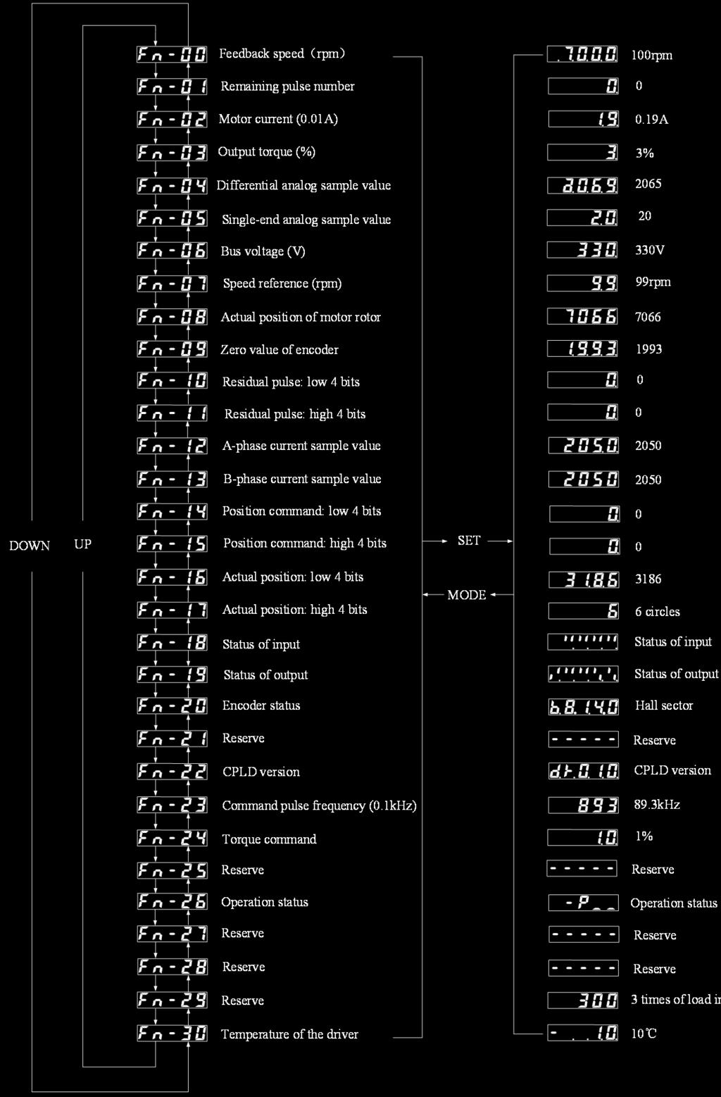
30 Fig. 3-4: Contents of Monitoring Menu 30
 Record the faults in operation of the")


 The auxiliary function is mainly used to improve")


31 (1) Operation status 3.4 Operation of Historical Fault Display (En-xx) Record the faults in operation of the servo unit and store the last four faults. The number, starting with En, will be displayed on the panel operation instrument. is displayed in case of no fault. The current fault code is displayed in case of any failure. Fig. 3-5: Operation Case of Historical Fault Menu 3.5 Operation of Auxiliary Function (dn-xx) The auxiliary function is mainly used to improve the flexibility and application of the servo motor, and includes the brake release test, JOG operation and drive initialization. The number, starting with Fdn, will be displayed on the panel operation instrument Brake Release Test At first, remove the brake resistor of the drive and set P0-02 as Then perform dn-00 operation to start the brake release test JOG Operation Fig. 3-6: Operation Case of Brake Resistor Release At first, set P0-04 in the speed mode, P0-02 password as 1234 and JOG operation speed P3-19 as the required value. Then perform dn-01operation to start JOG operation. 31
 and P0-02 initialization password with reference to the following table.")
32 Fig. 3-7 Operation Case of Speed Commissioning Drive initialization At first, set P0-01 as the corresponding motor model (see the motor configuration sheet in Appendix C) and P0-02 initialization password with reference to the following table. It is generally recommended to set the current loop bandwidth as 5K. If the electromagnetic noise of the motor is high, the P0-02 can be changed into 2.5K Drive resetting Fig. 3-8: Operation Case of Drive Initialization Drive resetting is equivalent to restart of the power supply in case of failure. Find dn-06 and press Enter. The DSP program version number will flash on the panel, and the relay actuation sound will be uttered. Thus, resetting is completed. Note: The multiplexed encoder does not support soft resetting. 32
33 Chapter IV Parameters 4.1 Summary of Parameters Parameters are divided into 7 segments: P0-P6. 60ST-M06020 (with G drive) is taken as an example of factory settings in the following table. P0 segment parameters S/N Items Default value Unit Manufacturer code 0 Version No Motor code Password Initial status display Control mode selection Alarm shield Function option Drive configuration Function option Maximum current limit of drive P1 segment parameters S/N Items Default value Unit Manufacturer code interface configuration and 1# oscilloscope channel display # and 3# oscilloscope channel display communication protocol address Command pulse filter 0 10ns 14 5 Feedback pulse bandwidth filtering number 0 10ns 15 6 Inversion of input port of low four bits Inversion of input port of high four bits Input IO port repositioning 1 Hd Input IO port repositioning 2 H657A Output port inversion Input command inversion DO3 output selection control E2PROM protection Parameter protection Input port filter 0 0.5ms MODBUS frame interval setting CAN communication baud rate CAN sending ID CAN receiving ID
34 P2 segment parameters S/N Items Default value Unit Manufacturer code 0 Position loop proportion 30 1/s 30 1 Reserve 2 Position loop feedforward 0 1% 32 3 Denominator 1 of electronic gear ratio Numerator 1 of electronic gear ratio Denominator 2 of electronic gear ratio Numerator 2 of electronic gear ratio Filter cutoff frequency of position loop feedforward 0 Hz 37 8 Filter cutoff frequency of position loop output 0 Hz 38 9 Numerator of electronic gear ratio of encoder output Positioning completion range 10 Pulse Position-tolerance detection range Pulse Oblique wave function of position command *Pulse/ms Denominator 1 of electronic gear ratio of encoder output Command pulse mode Delay time setting of release signal of output brake after switching-on of SON 0 ms Delay time setting of lock signal of output brake after switching-off of SON 0 ms Minimum speed setting corresponding to lock signal output of output brake after switching-off of SON 0 rpm Output phase inversion Position command source Primary filter cutoff frequency of position command 0 Hz Average filter time 1 of position command 0 0.5ms Average filter time 2 of position command 0 0.5ms Reserve 24 Reserve 25 Reserve 26 Reserve 27 Reserve 28 Reserve 29 Reserve P3 segment parameters S/N Items Default value Unit Manufacturer code 0 Speed loop refreshing frequency Speed loop ratio Hz 61 2 Speed loop integral time constant 1 10 ms 62 3 Speed loop ratio Speed loop integral time constant
35 S/N Items Default value Unit Manufacturer code 5 PDF coefficient % 65 6 Speed loop feedforward coefficient 0 1% 66 7 Speed detection filter -1 Hz 67 8 Speed detection filter 2-1 Hz 68 9 Cutoff frequency of speed observer 1000 Hz Compensation coefficient of speed observer 0 1% Reserve 0 1/ Speed loop output filter -1 Hz Maximum forwarding speed limit -1 rpm Maximum reversing speed limit -1 rpm Acceleration time -1 ms Deceleration time -1 ms Disabling delay time 0 ms Speed loop command source JOG speed 100 rpm Center frequency of wave trap 0 HZ Width of wave trap 0 HZ Attenuation ratio of wave trap 0 1/ Multiple of rotation inertia 30 1/ P-PI switching mode Threshold of P-PI switching speed error Temperature alarm threshold Acceleration/deceleration time setting in position mode 2*Pulse /ms Fan start-up temperature setting Fan shutdown temperature 0 89 P4 segment parameters S/N Items Default value Unit Manufacturer code 0 Positive limit of internal moment Negative limit of internal moment Positive limit of external moment Negative limit of external moment Current detection filter -1 Hz 94 5 Current loop output filter -1 Hz 95 6 Current overload value / Allowable current overload time s 97 8 Brake cycle Brake duty cycle Brake threshold voltage value
36 S/N Items Default value Unit Manufacturer code 11 Brake close voltage value Set value of overvoltage Set value of undervoltage Maximum allowable working time of braking resistor ms Command source in moment mode Basic value of software overcurrent 0 1/ Reaching of set value of moment 0 1/ Speed limit selection source in moment mode Torque complete time 0 0.5ms 109 P5 segment parameters S/N Items Default Delivery Unit value code 0 Speed amplitude limit in moment mode 100 rpm Zero offset setting of single-end analog Gain setting of single-end analog control 100 rpm/v Dead zone setting of single-end analog control 300 mv Internal speed 1 0 rpm Internal speed 2 0 rpm Internal speed 3 0 rpm Internal speed 4 0 rpm Negative pressure treatment of single-end differential analog Filter coefficient of single-end analog 990 1/ Zero drift setting of differential analog Gain of differential analog Dead zone of differential analog Filter coefficient of differential analog 990 1/ Reaching set value of speed in speed mode 0 rpm Parameter Details Details of P0 segment parameters S/N Items Functions Parameter range 0 Software version To inquire software version number, but no change is allowed Motor code 1 See the current motor model in the motor configuration sheet in Appendix C (the displayed code of the multiplexed motor is in Appendix C). 2 The parameter should be modified when various motors are used After the motor is selected, the password must be set in the Dn-02 interface to initialize motor settings; otherwise, the alarm (24) will be sent. 2 Password 1 The motor initialization password is set according to the following


37 S/N Items Functions figure. Parameter range 2 The password of braking resistor test is Initial status display 4 Control mode selection Alarm shield setting 3 The password of zero adjustment and self-test of the encoder is The offset of the displayed value corresponds to the menu Fn. Specific offsets are as follows: 0 corresponds to Fn-00, 1 to Fn-01, and so on. To set the control mode of the driver via this parameter: 0: Position mode 1: Speed mode 2: Moment mode 3: Moment and position mixed mode 4: Moment and speed mixed mode 5: Speed and position mixed mode The parameters are set based on the 5-digit display panel. The corresponding functions of each display panel are as follows ffff 5 When several alarms should be shielded, increase the shield value of the corresponding display panel. Example: To shield No. 26 and 2 alarm, the parameter should be set as : 37


38 S/N Items Functions To shield No. 37, 11 and 54 alarm, the parameter should be set as : Parameter range To shield No. 26, 11, 54 and 32 alarm, the parameter should be set as : To shield all alarms included in the parameter description, the parameter should be set as : The parameters are set based on the 5-digit display panel. The Function option 1 corresponding functions of each display panel are as follows Drive configuration The parameters are set based on the 5-digit display panel. The corresponding functions of each display panel are as follows. 7 8 Function option 2 The parameters are set based on the 5-digit display panel. The corresponding functions of each display panel are as follows. 38


39 S/N Items Functions Parameter range 9 Maximum current limit of drive Unit: 0.01A Details of P1 segment parameters S/N Items Functions 232 interface configuration and The parameters are set based on the 5-digit display panel. The 1# oscilloscope channel display corresponding functions of each display panel are as follows. Parameter range 0 1 Display of 2# and 3# oscilloscope channel The parameters are set based on the 5-digit display panel. The corresponding functions of each display panel are as follows. 39


40 S/N Items Functions Parameter range 485 serial protocol The parameters are set based on the 5-digit display panel. The corresponding functions of each display panel are as follows. 2 3 ID address of 485 ID address of 485: to set the equipment address in 485 communication Command pulse filter Feedback pulse bandwidth 5 filtering number Inversion of input port of low 6 four bits The input command is filtered, with the basic time unit of 10ns. If the parameter is set as 5, the command filtration time is 5*10ns=50ns Conclusion: the longer the command filtration time is, the better the anti-jamming performance of signal is. However, the set value must not be too large; otherwise, the normal signal will be affected. The same as the parameter P The parameters are set based on the 5-digit display panel. The corresponding functions of each display panel are as follows. 40

41 S/N Items Functions Parameter range Inversion of input port of high four bits The parameters are set based on the 5-digit display panel. The corresponding functions of each display panel are as follows. 7 8 Input IO port repositioning 1 The parameters are set based on the 5-digit display panel. The corresponding functions of each display panel are as follows. 41

42 S/N Items Functions Parameter range 9 Input IO port repositioning 2 The parameters are set based on the 5-digit display panel. The corresponding functions of each display panel are as follows. 42


43 S/N Items Functions Parameter range Output port inversion The parameters are set based on the 5-digit display panel. The corresponding functions of each display panel are as follows Input command inversion 12 DO3 output selection control Inversion of input command. 0: no inversion. 1: inversion. The parameters are set based on the 5-digit display panel. The corresponding functions of each display panel are as follows. 43


44 S/N Items Functions Parameter range 13 Write 485 data into E2PROM. 14 Parameter protection 15 Input port filter 16 MODBUS frame interval setting 17 CAN communication baud rate 18 CAN sending ID 19 CAN receiving ID 0: not write into E2PROM. 1: write into E2PROM. 0: the parameter panel can be modified. 1: the parameter panel cannot be modified. Unit: 0.5ms Valid for all input IO. Unit: 0.1ms 0: default 1.5 characters. 0: 50K 1: 100K 2: 125K 3: 250K 4: 500K 5: 1M Details of P2 segment parameters S/N Items Functions The position loop proportion is directly related to the response speed of the position loop. On the premise of no vibration or noise, the position loop gain of the mechanical system can be 0 Position loop proportion increased to accelerate the system response, and reduce the positioning error and time. If the gain is too large, the mechanical vibration may be caused and the system position may be subject to excessive adjustment. 1 Reserve 2 Position loop feedforward coefficient In the case of smooth change of position control command, the gain can be increased to increase the position follow-up error; Parameter range
45 S/N Items Functions Parameter range otherwise, the gain can be decreased to reduce rotational vibration of the mechanism. The feedforward coefficient can be set according to the percentage. 1 To set the frequency division of the position command 3 Denominator 1 of electronic gear ratio pulse (electronic gear). 2 In the position control mode, P2-03 and P2-04 parameter settings easily match a variety of pulse sources in order to achieve the desired control resolution (i.e., the angle / pulse) Numerator 1 of electronic gear ratio 3 P G = N C 4 P: number of pulses of the input command; G: electronic gear ratio, P2-04/P2-03. N: number of motor coils; C: Photoelectric encoder resolution/rotation, the system motor adopts encoder 2500 resolution. For example, if input 8000 pulses, motor operates a cycle Then N=1; P=8000; and C=2500. Thus, G=5/4. Set P2-04 as and P2-03 as 4. 4 The recommended range of electronic gear rate: 1/50 G 50 5 Denominator 2 of electronic gear ratio 6 Numerator 2 of electronic gear ratio Set the cutoff frequency (Hz) of the low-pass filter of the position loop feedforward. 7 Improve the stability of composite position control. Filter cutoff frequency of position loop The larger the parameter is, the higher the cutoff frequency of feedforward the filter is. Noise can be easily generated in motor operation, and the position may be subject to excessive adjustment. Filtration will not be done when the value is no more than 0. 8 Set the cutoff frequency (Hz) of the low-pass filter of the Filter cutoff frequency of position loop position loop output. output Filtration will not be done when the value is no more than Divide the frequency of the encoder output pulse in the integer or decimal form, in combination with P2-13. Note: The parameter should be smaller than that of P2-13 to ensure frequency-dividing output. P2-13 = frequency output of encoder P2-09 = 2 P2-13 = 5 Numerator of electronic gear ratio of Example: 2-frequency output of encoder: encoder output P2-09 = 1 The parameter is a basis to judge whether the drive is positioned in the position control mode. When the number of residual pulses in the offset counter is less than or equal to the set value, the drive positioning is completed. The signal will be 10 Positioning completion range COIN ON after positioning; otherwise, the signal will be COIN OFF. The positioning signal COIN will be outputted in the position control mode. The speed signal SCMP will be outputted in other control modes


46 S/N Items Functions Parameter range The basic unit is one pulse. AS one output port is used for position, speed and moment output, the priority of the three effective parameters is as follows: moment > speed > position. If the moment value is negative, the moment will not be outputted. If the speed value is negative, the moment will not be outputted. To output the position, the speed and moment value must be negative. In the position control mode, when the count value of the position deviation counter exceeds the value of this parameter, 11 Position-tolerance detection range the servo driver sends the position tolerance alarm. 0/30000 When the parameter is less than or equal to 0, the position offset detection will not be effective. The basic unit is 100 pulses. This function is used for smoothly filtering the position pulse 12 Oblique wave function of position input. When this function is applied, the pulse may be subject to command lagging, but will not be lost. The set value is the pulse limit within 1ms. Divide the frequency of the encoder output pulse in the integer or decimal form, in combination with P2-09. Note: The parameter should be smaller than that of P2-09 to ensure frequency-dividing output. 13 Denominator 1 of electronic gear ratio Example: 2-frequency output of encoder: of encoder output P2-09 = P2-13 = frequency output of encoder P2-09 = 2 P2-13 = 5 Command pulse input mode The command parameters are set according to the hexadecimal requirements Delay time setting of release signal of output brake after switching-on of SON Unit: ms Note: If the set value is 0, the brake signal will not act. 46
47 S/N Items Functions Parameter range 16 Delay time setting of lock signal of Unit: ms output brake after switching-off of SON Note: If the set value is 0, the brake signal will not act. Minimum speed setting corresponding 17 to lock signal output of output brake Unit: rpm after switching-off of SON 18 Inversion of encoder output phase 0: no inversion. 1: inversion. 19 Position command source 0: set the external pulse. 1: 485 sending of pulse command. 20 Primary filter cutoff frequency of position command Unit: Hz 21 Average filter time 1 of position command Unit: 0.5ms (range: 0-256) Average filter time 2 of position command Unit: 0.5ms (range: 0-256) Reserve 24 Reserve 25 Reserve 26 Reserve 27 Reserve 28 Reserve 29 Reserve Details of P3 segment S/N Items Functions 0 Speed measurement mode 0: speed loop refreshing frequency 20K 1: speed loop refreshing frequency 2K 1 Speed loop proportional gain 1 The gain can be increased to improve the speed response. If the set value is too large, vibration and noise may be easily caused. This parameter can be reduced to improve the speed response and 2 Speed loop integral time reduce the speed control error. If the set value is too small, vibration constant 1 and noise may be easily caused. The larger the parameter is, the poorer the rigidity is. 3 Speed loop proportional gain 2 It has the same effects as P3-01 and should be switched by the switch in the second segment of speed loop proportional integral control. 4 Speed loop integral time It has the same effects as P3-02 and should be switched by the switch constant 2 in the second segment of speed loop proportional integral control. 5 PDF coefficient The speed loop PI is subject to composite PDFF control, and the PDF coefficient is the composite PI control coefficient. In the case of smooth change of speed control command, the gain can 6 be increased to increase the speed follow-up error. Speed loop feedforward In the case of non-smooth change of speed control command, the coefficient gain can be decreased to reduce the operational vibration of the mechanism. The low-pass filter is used for low speed detection. 7 Speed detection filter 1 The cutoff frequency of the filter can be reduced to improve the anti-jamming performance of the system. If the set value is too small, the dynamic response of the system, and even the motor may be Parameter range %-500%
48 S/N Items Functions Parameter range abnormal. 8 Speed detection filter 2 Hz Cutoff frequency of speed observer Cutoff frequency of speed observer The higher the speed is, the stabler the observer is, but the delay in Compensation coefficient of observation may be caused. The lower the speed is, the more speed observer sensitive the observer is, but oscillation may be caused Reserve The filtration parameter has obvious effects on improvement of the stable torque and control of the operating noise of the motor. The 12 Speed loop output filter above two aspects can be improved by reducing the cutoff frequency However, the cutoff frequency must not be too low; otherwise, the system operation will be affected. 13 Maximum forwarding speed limit Maximum motor CCW speed limit, using RPM as the basic unit Maximum reversing speed limit Maximum motor CW speed limit, using RPM as the basic unit Acceleration time Set the time of motor speed increase from 0 to rated speed (unit: ms) Deceleration time Set the time of motor speed decrease from rated speed to 0 (unit: ms) Disabling delay time IO disabling delay time (unit: ms) 0: position loop output; 1: single-end analog (SAIN and AGND) input; 2: P3-19 parameter setting; 3: Differential analog (AS+ and AS-) input; 18 Speed loop command source 4: Internal speed mode: speed source--p5-04\p5-05\p5-06\p5-07, with external IO speed selection control; 5: 485 sending of speed command. Note: If Mode 1 or 3 is selected, one IO port can be multiplexed into the analog + IO control direction mode. The IO port is used in the functions similar to command inversion. 19 JOG speed Set the JOG operation speed, with the basic unit of RPM It is the set value of mechanical resonance frequency. If P3-22 is set 20 Center frequency of wave trap as 0, this function will be OFF Unit: Hz 21 Width of wave trap Filter width of wave trap Unit: Hz Refer to the filter attenuation coefficient within the filter width of the 22 Attenuation coefficient of wave wave trap. The large this value is, the smaller the attenuation trap proportion is Unit: 1/ Rotation inertia ratio Refer to the ratio of the load inertia to motor shaft inertia, in : no switching 24 P-PI switching mode 1: switch according to the set current : switch according to the external IO. 25 Threshold of P-PI switching When the P-PI switching mode (P3-24) is set as 1, set the switching speed error threshold of the set current, in 1/ Temperature alarm threshold 27 Acceleration/deceleration time in position mode The parameter setting is not valid until the temperature detection function is enabled (enable the temperature sensor through P0-07). The larger this value is, the smaller the acceleration/deceleration is, and the longer the delay time is. In this case, the operation will be 0~
49 S/N Items Functions stable. (the acceleration is 150RPM/MS is the value is set as 1 ) Parameter range 28 Fan start-up temperature setting This parameter is used to set the fan start-up temperature. 0~999 When the parameter is more than 0, the fan will be started at the temperature higher than the value of P3-28 and shut 29 Setting of fan shutdown temperature down at the temperature lower than the value of P3-29. When the parameter is 0, the fan will be kept ON. When the parameter is less than 0, the fan will be kept OFF Details of P4 segment parameters S/N Items Functions Parameter range 0 Positive limit of internal moment Unit: 1/1000. The internal torque is continuously valid Negative limit of internal moment Unit: 1/1000. The internal torque is continuously valid Positive limit of external Unit: 1/1000. The external torque and internal torque are continuously moment valid and limited according to the minimum value Negative limit of external Unit: 1/1000. The external torque and internal torque are continuously moment valid and limited according to the minimum value Current detection filter Filter the actually detected current, in Hz Current loop output filter Filter the current loop output in Hz Current overload value Set the current overload value. This value is used in combination with the allowable P4-07 overload time. If the continuous output torque of the motor is larger than the set value and the time reaches the set time of P4-07, the drive will send the overload alarm. Unit: 1/ Allowable current overload Set the allowable P4-06 overload time. time Unit: 0.1s Brake cycle Set the braking cycle of the braking resistor, in 100us Brake duty cycle Set the duty ratio of release of the braking resistor (unit: 100us). The duty ratio of the brake must be less than or equal to the set braking cycle of P Brake threshold voltage value Used to set brake threshold voltage value, unit: V. 11 Brake close voltage value Used to set brake close voltage value, unit: V. 12 Set value of overvoltage Used to set overvoltage alarm threshold, unit: V. 13 Set value of undervoltage Used to set undervoltage alarm threshold, unit: V. 14 If the time of continuous operation of the braking resistor is more than Maximum allowable working P ms, the braking resistor will send the overload alarm. Unit: time of braking resistor 10ms. 0: speed loop output; 15 1: single-end analog (SAIN and AGND) input; Command source in moment 2: value corresponding to the internal parameter P3-19. mode 3: Differential analog (AS+ and AS-) input; 5: 485 sending of moment command. 16 Basic value of overload alarm The software overcurrent alarm 12 is determined in combination with start-up P4-06 and P4-07, generally set as The rated torque of the motor is 49
50 S/N Items Functions Parameter range used as the basic value. Unit: 1/1000; 1 As one output port is used for position, speed and moment output, the priority of the three effective parameters is as follows: moment > speed > 17 Moment setting position. 2 If the moment value is negative, the moment will not be outputted. If the speed value is negative, the moment will not be outputted. To output the position, the speed and moment value must be negative. 18 0: limited by the P5-0 parameter Speed limit selection in 1: jointly limited by the P5-0 parameter and single-end input moment mode 2: jointly limited by the P5-0 parameter and differential input Torque complete time 0.5 ms Details of P5 segment parameters S/N Items Functions Parameter range 0 Speed amplitude limit in The maximum speed is limited in the moment control mode. Unit: rpm moment mode 1 The zero point of analog is mainly used to eliminate the zero drift of analog command, set as follows: SAIN is connected to AGND in the single-end mode. SAIN is connected to the positive end, while AGND is connected to the negative end of analog. The voltage between SAIN and AGND is the zero-point voltage, generally 0V. Zero drifting of single-end Select the appropriate control functions corresponding to the parameter analog control P3-18 in the speed mode and P4-15 in the moment analog mode. Select the appropriate negative pressure treatment mode according to the parameter P5-08. Adjust the parameter into the P5-01 interface and press OK. Then press UP to adjust the zero drift. Finally press OK to save the setting. Refer to AD zero adjustment Gain of single-end analog control Motor speed corresponding to the external input voltage of 1V, in rpm/v. 3 Dead zone of single-end analog control Internal speed 1 Select the internal speed 1 as the speed command in the SC1Z OFF and SC2Z OFF mode of speed control Internal speed 2 Select the internal speed 2 as the speed command in the SC1Z ON and SC2Z OFF mode of speed control. 6 Internal speed 3 Select the internal speed 3 as the speed command in the SC1Z OFF and SC2Z ON mode of speed control. 7 Internal speed 4 Select the internal speed 4 as the speed command in the SC1Z ON and SC2Z ON mode of speed control. Negative pressure treatment of single-end differential analog 8 Bit0: negative pressure treatment of single-end analog, relative to the Optional bit of negative single-end ad zero point. pressure treatment of Bit1: negative pressure treatment of differential analog, relative to the single-end differential analog differential ad zero point. Bitx bit operation instructions 50
51 S/N Items Functions Parameter range 0: no negative pressure treatment. 1: the command of negative pressure treatment is considered 0. 9 Filter coefficient of single-end analog Filter the single-end input analog. 0 indicates no filter The zero point of analog is mainly used to eliminate the zero drift of analog command, set as follows: The differential part of external analog input is connected to AS+/AS-. The voltage between AS+ and AS- is the zero-point voltage, generally 0V. 10 Zero drift of differential Select the appropriate control functions corresponding to the parameter analog control P3-18 in the speed mode and P4-15 in the moment analog mode. Select the appropriate negative pressure treatment mode according to the parameter P5-08. Adjust the parameter into the P5-10 interface and press OK. Then press UP to adjust the zero drift. Finally press OK to save the setting. Refer to AD zero adjustment. 11 Gain of differential analog Motor speed corresponding to the external input voltage of 1V, in rpm/v. 12 Dead zone of differential analog 13 Filter coefficient of differential analog Filter the differential input analog. 0 indicates no filter The parameter is a basis to judge whether the drive reaches the set speed in the speed control mode. When the actual speed is less than or equal to the set value, the drive is considered conforming. The signal will be COIN ON when the speed is conforming; otherwise, the signal will be The speed reaches the set COIN OFF. 14 value in the speed control 2 As one output port is used for position, speed and moment output, the mode. priority of the three effective parameters is as follows: moment > speed > position. 3 If the moment value is negative, the moment will not be outputted. If the speed value is negative, the moment will not be outputted. To output the position, the speed and moment value must be negative. 51
52 Chapter V Operation 5.1 Working Sequence Power-on sequences (1)G-B Series (2)G2 Series 52
 signal is OFF.")
53 1. Connect power to the main circuit power input terminals (three phases to L1, L2 and L3, single phase to L1 and L3) via the AC contactor. 2. Switch on the power L1 and L2 of the control circuit at the same time with or before the main circuit power. If only the control circuit power is connected, the servo readiness (SRDY) signal is OFF. 3.After the main circuit power is turned on, servo readiness signal (SRDY) is ON (with delay 1.5s). Then it receives servo enabling (SON) signal, servo enabling is effective, the driver output is effective and it is in the running state. If the servo enabling is ineffective, alarm may be sent, the base circuit would be shut down, and the motor is in a free state. 4. When the servo enabling is connected concurrently with the power, the base circuit is connected in 1.5 seconds. 5. Frequent connection and disconnection to the power may damage the soft-start circuit and the dynamic braking circuit. On/off frequency should be no more than five times per hour and less than 30 times a day. If the driver or motor is overheated, wait for 30 minutes after troubleshooting before connecting it to the power Timing diagram Power connection sequences and alarm sequences: 53
 Allowable frequency of servo drive If high frequency is required, check whether it is within the allowed frequency range.")
54 Fig. 6-1: Power-on Sequence Diagra m Fig. 6-2: Alarm Sequence Diagram 5.2 NOTES 1. The start/stop frequency is limited by the servo drive and motor and must meet the two conditions at the same time. 1) Allowable frequency of servo drive If high frequency is required, check whether it is within the allowed frequency range. The allowed frequency range varies along with the motor type, capacity, load inertia and motor speed. Firstly set the deceleration time to prevent too large renewable energy (in the position control mode, set the output pulse acceleration and deceleration time for the host controller). When the load inertia is m times of the motor inertia, the frequency allowed for the servo motor is as follows: Multiple of load inertia Allowed frequency m 3 > 100 times / minute; acceleration and deceleration time: 60 ms or less m 5 60 to 100 times / minute; acceleration and deceleration time: 150 ms or less m>5 < 60 times / minute; acceleration and deceleration time: 150 ms or less If it still fails to meet the requirements, reduce the internal torque limit (parameter P4-00 and P4-01) and lower down the maximum motor speed (parameter P3-13 and P3-14). 2) The allowed frequency for the servo motor varies with the load conditions, running time and other factors. Please refer to the motor manual. 2. Generally, if the multiple of load inertia is less than five times, use the motor under large inertia conditions. Main circuit over voltage or braking anomalies may occur from time to time and the countermeasures are as follows: 1) Reduce the internal torque limit (Parameter P4-00 and P4-01). 54

55 2) Reduce the maximum speed of the motor (Parameter P3-13 and P3-14). 3) Providing an additional regeneration device. 3. As the servo driver is provided with a power supply for the encoder, to ensure normal operation of the encoder, the output voltage should be maintained at 5V ± 5%. If long cables are used, voltage loss may occur. In this case, please use the multi-core encoder for power supply in order to reduce the voltage drop of the cable line. 5.3 Check before Operation After completing installation and wiring, check the following items before power connection: 1. Whether TB wiring of power terminal is correct and reliable and whether the input voltage is correct; 2. Whether power line or the motor line is short circuit or properly grounded; 3. Whether the encoder cable is connected correctly; 4. Whether the control signal terminal is properly connected? Whether the power polarity and size are correct; 5. Whether the driver and the motor are firmly fixed; 6. Whether the motor shaft is not connected to the load. 5.4 Position control mode Wiring 1. The three-phase AC220V terminal of the main circuit should be connected to the terminal L1, L2 and L3, and the single-phase AC220V terminal should be connected to the terminal L1 and L3. 2. The control voltage terminal L1C and L2C should be connected to the single-phase AC220V terminal. 3. Encoder signal connector CN1 should be properly connected with the servo motor; 4. Control signal connector CN2 should be connected as per the figure shown Operations Fig. 6-4: Simple Wiring Diagram of Position Control Mode 1. Turn on the control circuit power supply and main power and the monitor displays; 2. Set parameter values according to in the table below and write the parameters into EEPROM 55
56 Parameter No. Meanings Parameter value Default value P0-04 Control mode selection 0 0 P2-14 Pulse input mode selection To be set by the user 0 P1-04 Command pulse filter To be set by the user 0 P1-05 Feedback pulse bandwidth filtering number To be set by the user 0 P1-06 Inversion of input IO port To be set by the user 0 P1-08 Input IO port repositioning 1 To be set by the user Hd410 P1-09 Input IO port repositioning 2 To be set by the user H657A P2-00 Position loop proportion To be set by the user 30 P2-02 Position loop feedforward To be set by the user 0 P2-04 Electronic gear numerator To be set by the user 1 P2-03 Electronic gear denominator To be set by the user 1 P2-12 Smooth filter of position command To be set by the user 5000 P4-19 Invalid acceleration/deceleration control in position mode To be set by the user 0 Instructions of parameter setting: At first, set the parameter of P0-04 control as 0, select the position control mode, and set the parameter P2-14 of input command as pulse + direction, CW/CCW or AB quadrature pulse. For interference resistance in the application environment, set the appropriate number of command and feedback filters, with the basic unit of 10ns. Refer to the parameter P1-04 and P1-05 for filter setting. Secondly, relocate all input IO ports of G series. The default configuration is set in the factory. Select the appropriate repositioning mode according to the parameter P1-08 and P1-09. Refer to P1-06 for input port inversion. Again, the factory settings of pulse frequency and control speed of the system may not meet the requirements. The user can select the appropriate electronic gear ratio with reference to P2-03 and P2-04. The electronic gear ratio can be set with reference to If the host acceleration/deceleration curve cannot meet the system requirements, the user can select the appropriate function of smooth filtration of position command with reference to P2-12. Finally, disconnect the power supply and start the control motor after setting the control parameter of the upper layer of position control according to the basic parameters of the motor, including the rated current, rated torque and rated speed of the motor, relevant moment limits, etc. 3. After the alarm and anomaly are eliminated, enable the servo drive (SON-ON). Send the low-frequency pulse signal from the controller to the drive to make the motor operate at a low speed. If the motor operation cannot meet the user s requirements, relevant setting can be done according to the way of gain adjustment in Setting of Electronic gear The unit pulse command input into the device can be defined through the electronic gear to move the transmission device into any position. The gear ratio and reduction ratio of the transmission system and the wire number of the motor encoder are not required for the pulse command generated in host control. The following table describes the variables of the electronic gear. Variable Variable description Drive value C Encoder wire number 2500 Pt Encoder wire number (pulse/turn) 4*C pulses R=H/K, where: R P PC Reduction ratio Amount of movement of one command pulse Number of command pulses within one turn of load shaft H: number of motor turns; K: load shaft turns. 56
 Where, P C Number of amount of movement within one turn of load shaft Amount of movement of one pulse( P) The final result should be subject to reduction until the numerator and")
, Where, PC M P R P C Example analysis: The encoder wire number C is 2500, the reduction ratio is 0.")
57 Formula: Pitch D Electronic gear ratio( N M Screw pitch (mm) Roller diameter (mm) ( Pt) ) ( P ) ( R) C (P t = Encoder resolution,p c = Number of command pulses within one turn of load shaft,r = Reduction ratio) Where, P C Number of amount of movement within one turn of load shaft Amount of movement of one pulse( P) The final result should be subject to reduction until the numerator and denominator are no more than 32767, and the ratio should be guaranteed Electronicgear ratio ) 100; ( M N 1. Analysis of electronic gear with ball screw Ball screw: N Pt Pitch Electronicgear ratio( ), Where, PC M P R P C Example analysis: The encoder wire number C is 2500, the reduction ratio is 0.5, the pitch is 10mm, and the equivalent of one pulse is 0.001mm. The calculated electronic gear ratio is: Calculate one encoder turn Pt P 4 C t Calculate P C Pitch 10 PC P Calculate the electronic gear ratio N Pt Electronic gear ratio( ) M P R Set the numerator of the electronic gear ratio as 2 and the denominator as Analysis of electronic gear ratio with index plate C 2 1 Load on the index plate: 57


58 N Pt 360 Electronic gear ratio( ), Where, PC M P R P C o Example analysis: given that the encoder wire number is 2500, the pulse equivalent is 0.1 and the reduction ratio is 1/5, the electronic gear ratio is calculated as follows. Calculate one encoder turn Pt P 4 C t Calculate P C PC 3600 P 0.1 Calculate the electronic gear ratio N Pt Electronicgear ratio( ) M P R 1 C Set the numerator of the electronic gear ratio as 125 and the denominator as Analysis of electronic gear with conveyor belt Fig. 6-5 Working Diagram of Belt Loads on the conveyor belt: Electronic gear ratio( N Pt ), Where, PC M P R C D P Given that the encoder wire number is 2500, the reduction ratio is 1/10, the diameter of the roller screw is 200mm and the pulse equivalent is 0.001mm, the electronic gear ratio is calculated as follows. Calculate one encoder turn Pt P 4 C t Calculate P C D PC P Calculate the electronic gear ratio Electronic gear ratio( N M Pt ) P R 1 C Set the numerator of the electronic gear ratio as 2500 and the denominator as Relation Table of Electronic Gear Ratio and Motor Rotation Turns Table 6.1: The relationship between pulse number and number of rotations Number of pulses Number of motor rotations; Numerator of electronic gear ratio: Denominator of electronic gear ratio: 58
59 (P2-04) (p2-03) P2-04 P / Relation Table of Electronic Gear Ratio and Rotational Speed Input pulse frequency (Hz) Table 6.2: The relationship between pulse frequency and rotation speed Motor speed (r/min) Frequency 60 (P2-04) (p2-03) Numerator of electronic gear ratio: P2-04 Denominator of electronic gear ratio: 300k k k k k k k Gain adjustment The position and speed bandwidth must be selected according to the mechanical rigidity and application. The mechanical rigidity of the conveyor connected by the belt is low, so the bandwidth can be set as a small value. The mechanical rigidity of the ball screw driven by the reducer is medium, the bandwidth can be set as a medium value. The rigidity of the direct drive type ball screw or linear motor is high, the bandwidth can be set as a large value. If the mechanical properties are unknown, the gain can be increased gradually to increase the bandwidth until resonance occurs. Then the gain can be reduced. If one parameter of the servo gain is changed, the other parameters should be adjusted. Any parameter must not be changed significantly. Generally the following principles should be observed for servo parameter modification steps. Increase the response. P2-03 Decrease the response and inhibit the vibration and excessive adjustment. 1. Increase the proportional coefficient of the speed loop. 2. Reduce the integral time constant of the speed loop. 3. Increase the position loop gain. 1. Decrease the position loop gain. 2. Increase the integral time constant of the speed loop. 3. Reduce the position loop gain. Steps of gain adjustment of speed control: 1. Set the appropriate load moment of inertia. 2. Set the integral time constant of the speed loop as the larger value. 3. Increase the proportional coefficient of the speed loop gain while avoiding system oscillation. 4. Decrease the integral time constant of the speed loop while avoiding system oscillation. 5. If the gain cannot be increased and the expected response cannot be achieved as a result of resonance of the mechanical system, motor noise, etc., adjust the time constant of the torque filter and continue the above steps. Steps of gain adjustment of position control: 1. Set the appropriate load moment of inertia. 2. Set the integral time constant of the speed loop as the larger value. 3. Increase the proportional coefficient of the speed loop gain while avoiding system oscillation. 4. Decrease the integral time constant of the speed loop while avoiding system oscillation. 5. Increase the position loop proportion while avoiding system oscillation. 6. If the gain cannot be increased and the expected response cannot be achieved as a result of resonance of the mechanical system, motor noise, etc., adjust the time constant of the torque filter and continue the above steps. 59


60 7. If smaller positioning error and rapider positioning are required, the position feedforward can be increased properly Overtravel limit The overtravel limit function is a safety function used to enable the limit switch to stop the motor in a forced manner when the mechanical movement is beyond the design range of safety travel. Fig. 6-6 Workbench Table It is recommended to use the normally closed contact of the limit switch. The limit switch should be closed within the safety scope and open in the case of overtravel. When the limit switch is connected to Forward Drive Stop (FSTP) and Reverse Drive Stop (RSTP), this function will fail if the drive stop input function is not selected according to the parameter P1-8 and P1-9. If selected in P1-8 and P1-9 input port repositioning, the drive stop function will be enabled. 5.5 Speed control mode Analog input speed mode Fig. 6-7 Wiring Diagram of Speed Control Model Turn on the control circuit power supply and main power and the monitor displays; Set parameter values according to in the table below and write the parameters into EEPROM Parameter No. Meanings Parameter value Default value 60
61 P0-04 Control mode selection 1 0 P3-18 Speed command source To be set by the user 0 P5-08 Negative pressure treatment of analog To be set by the user 0 P5-09 Filter coefficient of single-end analog To be set by the user 990 P5-13 Filter coefficient of differential analog To be set by the user 990 P5-01 Zero adjustment parameter of single-end analog To be set by the user 0 P5-10 Zero adjustment parameter of differential analog To be set by the user 2048 P1-06 Inversion of input IO port To be set by the user 0 P1-08 Input IO port repositioning 1 To be set by the user Hd410 P1-09 Input IO port repositioning 2 To be set by the user H657A P1-12 Output IO port DO3 repositioning To be set by the user 0 P3-00 Selection of speed PI mode To be set by the user 0 P3-01 Speed loop proportion To be set by the user 100 P3-02 Speed loop integral To be set by the user 10 P3-05 PDFF coefficient of speed loop To be set by the user 1000 P3-06 Speed loop feedforward coefficient To be set by the user 0 P3-07 Speed detection filter 1 To be set by the user -1 P3-08 Speed detection filter 2 To be set by the user -1 P3-09 Cutoff frequency of speed observer To be set by the user 100 P3-10 Weight setting of detector 1 and detector 2 To be set by the user 0 P3-12 Speed loop output filter To be set by the user -1 P3-13 Setting of maximum forwarding speed To be set by the user -1 P3-14 Setting of maximum reversing speed To be set by the user -1 P3-15 Setting of acceleration time To be set by the user -1 P3-16 Setting of deceleration time To be set by the user -1 P3-19 JOG speed setting To be set by the user 100 P5-02 Gain of analog control To be set by the user 100 P5-03 Dead zone of analog control To be set by the user 300 P5-04 Internal speed 1 To be set by the user 0 P5-05 Internal speed 2 To be set by the user 0 P5-06 Internal speed 3 To be set by the user 0 P5-07 Internal speed 4 To be set by the user 0 Instructions of parameter setting: At first, set the P0-04 control mode as the speed control mode, and determine the source of command speed according to the speed command source parameter P3-18. Set the parameter P3-18 in the speed control mode. 0: the speed command comes from the PULSE and DIR terminal of CN2; 1: set the speed command source designated in the parameter P5-08 in the differential analog control mode. 2: the operation speed is the value designated in the parameter P3-19 in the JOG mode. 3: select the analog + IO port mode. 4: select the internal register model. In this case, the speed is controlled through the DI port designated in P1-08 and P1-09. Adjust specific settings with reference to the parameter P5-04 to P5-07. Remark: 1) Two-way AD mode: the zero speed locking port can be specified through P1-08 and P ) Single-end AD + direction mode: the zero speed locking port and direction control port can be specified through P1-08 and P1-09. Then, reposition the corresponding IO port according to the applied external IO port. Refer to P1-08 and P1-09 for repositioning parameters. If inversion of input IP logic level is required, refer to P1-06. If the output IO is related, refer to P1-12 to select multiple output functions of DO3, and DO1 and DO2 cannot be used to achieve the repositioning function. DO1 is used for servo readiness signal output, and DO2 for servo alarm signal output. 61
 Set the external input voltage as 0V. 2) Set P0-04 as the speed mode.")
62 Again, specific operations should be done according to the control source. Before using external AD for speed input, it is necessary to conduct the following steps for speed zero setting: 1) Set the external input voltage as 0V. 2) Set P0-04 as the speed mode. 3) Specify the parameter P3-18 as the speed command source. 4) Set the drive in the parameter setting mode. The parameter should be set through P5-01 in the single-end mode and P5-10 in the differential mode. 5) Press UP. In this case, the zero-point value will be sampled and calculated automatically by the drive. Continuously adjust the zero point several times. If the zero-point change is not large but close to 2048 (close to 0 in the single-end mode), zero adjustment can be considered successful. Press ENTER to save the zero-point value. Thus zero adjustment is finished, as shown in the following figure. Fig. 6-8 Block Chart of Zero Adjustment 6) Select the appropriate control gain and dead zone according to P5-02 and P5-03 in the single-end mode and according to P5-11 and P5-12 in the differential mode Internal speed control 1 Set the internal speed parameter P5-04 to P Select the internal speed switching IO function by IO port repositioning. Refer to the parameter P1-08 and P JOG operation 1 Set the JOG speed with reference to the parameter P Refer to Chapter III Instructions of JOG Operation of the Operation Manual. Finally, select the appropriate deceleration parameter P3-15 and P3-16 according to the host control curve. If pulse control is involved, refer to the guide of position control. Set the basic parameters of the motor according to the nameplate, such as the rated current, rated speed, rated torque and inertia. Select the appropriate inertia according to the load inertia. JOG operation will be started after the power supply is cut off. 3 After the alarm and anomaly are eliminated, enable the servo drive (SON-ON). Send the low-frequency pulse signal from the controller to the drive to make the motor operate at a low speed. If the motor operation cannot meet the user s requirements, relevant setting can be done according to the way of gain adjustment in
63 5.6 Torque Control Mode Fig. 6-9 Wiring Diagram of Torque Control Mode 1. Turn on the control circuit power supply and main power and the monitor displays; 2. Set parameter values according to in the table below and write the parameters into EEPROM Parameter No. Meanings Parameter value Default value P0-04 Control mode selection 2 0 P4-15 Torque command source To be set by the user 0 P5-08 Negative pressure treatment of analog To be set by the user 0 P5-01 Zero adjustment parameter of single-end analog To be set by the user 10 P5-02 Gain of single-end analog To be set by the user 100 P5-03 Dead zone of single-end analog To be set by the user 10 P5-09 Filter coefficient of single-end analog To be set by the user 990 P5-10 Zero adjustment parameter of differential analog To be set by the user 0 P1-06 Inversion of input IO port To be set by the user 0 P5-11 Gain of single-end analog To be set by the user 100 P5-12 Dead zone of single-end analog To be set by the user 10 P5-13 Filter coefficient of differential analog To be set by the user 990 P1-08 Input IO port repositioning 1 To be set by the user Hd410 P1-09 Input IO port repositioning 2 To be set by the user H657A P1-12 Output IO port DO3 repositioning To be set by the user 0 P4-00 CCW maximum torque limit To be set by the user 3000 P4-01 CW maximum torque limit To be set by the user 3000 P4-18 Speed limit selection in moment mode To be set by the user 0 P5-00 Speed limit of torque mode To be set by the user 500 Parameter description: At first, select the torque control mode according to the control mode parameter P0-04 and the appropriate torque source according to the torque source parameter P4-15. The analog control of the same speed mode is set in the same method. Select the negative pressure treatment of analog according to P
64 Then select the analog control mode. If zero adjustment of analog is involved, refer to zero adjustment requirements in 6.5. For repositioning of the input and output IO port, refer to the parameter P1-08 and P1-09. For IO port inversion, refer to the parameter P1-06. For DO3 repositioning of the output port, refer to the parameter P1-12. Again, several limit parameters should be set in the torque control mode, including the maximum torque limit. Set the torque limits in both directions with reference to the parameter P4-06 and P4-01. Set the speed limit of the torque mode with reference to the parameter P5-00. Finally, after setting the function parameters, set the appropriate motor parameters according to the nameplate, including the rated current, rated torque, rated speed and inertia. Start operation after the power supply is cut off. 3. After the alarm and anomaly are eliminated, enable the servo drive (SON-ON). Send the low-frequency pulse signal from the controller to the drive to make the motor operate at a low speed. If the motor operation cannot meet the user s requirements, relevant setting can be done according to the way of gain adjustment in
65 Chapter VI Communication Function 6.1 Communication Overview The G2 series general AC servo drive has the function of RS485 and 232 serial communication. With the third-party PLC or PC, this function can be used, through the Modbus protocol, to read and set the internal parameters of the drive, monitor the internal status of the drive, complete specific functions, etc. The 232 serial communication function can be applied in combination with the PC debug software to realize parameter reading, parameter setting, parameter export, parameter import, and monitoring of internal operation curve of the drive. Refer to the instructions of PC debug software for specific operations. 6.2 Overview of Communication Parameters P1-03 Drive communication address number Parameter range Default value Unit Remark None 0 is the broadcast address. When RS-485 is used, the communication address numbers of different drives on the same bus should be set according to the parameter in the communication address of the servo drive. These communication address numbers should be unique on the same bus. The drives on the same bus must have different address numbers; otherwise, abnormal communication will be caused. Refer to the following table for the parameter setting range and method. P1-02 Drive communication protocol Parameter range Default value Unit Remark None Set according to the hexadecimal requirements. When RS-485 is used, the Modbus communication protocol format, communication speed, communication mode, 485 communication ON/OFF and other functions of the servo drive should be set according to the parameter P1-02. Refer to the following table for P1-02 parameter setting. The specific parameters are displayed in sequence in the ABCD form, starting with H. A indicates the thousands place, B indicates the hundreds place, C indicates the decade place and D indicates the units place. LED bits H A- B- C D LED contents Indicate the 1: enable : ASSCI 0: 7N2 0: 4800 It can be seen in the table that hexadecimal 485 communication 0: disable can 485. be enabled or 0:RTU disabled according1: to7e1 the value of A 1:9600 and select the Modbus communication form according to the value of B, the communication protocol according to the value of C and the communication baud rate according to the value of D. In the C form, N indicates no parity check, E indicates even parity check and O indicates odd parity check. The digits 7 and 8 indicates 7bit or 8bit, followed by 1 and 2 indicating the stop bit. Example: 7N2 means the data bit width 7bit, with no parity check and 2 stop bits. 6.3 MODBUS Communication Protocol When the RS-232/485 serial communication interface is used, a unique address number must be preset in P1-03 for each servo drive. The drive is controlled by the host according to the set address number. The MODBUS communication protocol is used in communication. MODBUS can be applied in two modes: ASCII mode and RTU mode. The user can perform corresponding settings according to the parameter P1-02. The details of specific commands of MODBUS are shown below Code meaning (1) ASCII mode 65
66 Each 8-bit digit is composed of two ASCII characters. For example, 46H, a one-byte digit (hexadecimal) is expressed as ASCII 46, including 4 as the ASCII code (34H) and 6 as the ASCII code (34H). The ASCII code includes the number from 0 to 9 and letter from A to F, as shown in the following table. Character Symbol (2) RTU mode 30H 31H 32H 33H 34H 35H 36H 37H Character Symbol 8 9 A B C D E F (2) RTU mode 38H 39H 41H 42H 43H 44H 45H 46H (2) RTU mode Each 8-bit digit is composed of two 4-bit hexadecimal characters, such as 46H, a one-byte digit Character structure 10bit character box (for 7-bit characters) 11 bit character box (for 8-bit characters) Communication data structure (1) Communication data format box ASCII mode: RTU mode: STX ADR CMD DATA(n-1).. DATA(0) LRC End 1 End 0 STX ADR CMD DATA(n-1).. DATA(0) CRC End 1 Starting character : (3AH) Communication address: one byte includes two ASCII codes. Command code: one byte includes two ASCII codes. Data contents: n characters = 2*n bytes, including 4*n ASCII codes, n 12 Checksum: one byte includes two ASCII codes. End code 1: (0DH) (CR) End code 0: (0AH) (LF) The idle bus space is larger than 10ms. Communication address: one byte Command code: one byte Data contents: n characters =2*n bytes, n 12 Checksum: one byte The idle bus space is larger than 10ms. (2) Description of communication data format box The details of the communication data format box are described as follows: STX (communication start) ASCII mode: the ASCII code using : as the starting symbol of the data frame is 3AH. RTU mode: use the idle bus space of more than 10ms as the starting symbol of the data frame. ADR (communication address) Set the ADR value according to the set value of P1-03. See the limits of legal characters within the range of P1-03. ASCII mode: ADR=16, corresponding to the hexadecimal value 10H and ASCII code 31H and 30H. RTU mode: ADR=16, corresponding to the hexadecimal value 10H and RTU value 10H. CMD (command code) and DATA (data character) The data character format is related to the command code. The commonly used command codes are introduced in details as follows: 66


67 (3) Command code: 03H, N-word reading. The maximum value of N is 12. Take the starting address 0002H of No. 01H servo drive as an example. Continuously read two characters. ASCII mode: RTU mode: 67
 LRC (ASCII mode) and CRC (RTU mode) check and calculation: ASCII mode: LRC check is applied in the ASCII mode.")
.")
68 (4) Command code: 06H, one-word character. Example: write 100 (0064H) into the address 0002H of the 01H servo drive. ASCII mode: RTU mode: (5) LRC (ASCII mode) and CRC (RTU mode) check and calculation: ASCII mode: LRC check is applied in the ASCII mode. The LRC frame errors are added from ADR to the last data. The part of the result exceeding 256 is eliminated based on 256 (example: if the result is hexadecimal 128H, and the result is 28H after elimination). Then the binary complementary code is calculated. The final result is the LRC checksum. Example: read one word from the 0003H address of No. 01H servo drive. STX : ADR 0 1 CMD 0 3 Location of initial 0 data 0 68
69 Number of data LRC End 1 End F 8 (0DH) (CR) (0AH) (LF) 01H + 03H + 00H + 03H + 00H + 01H = 08H. The binary complementary code of 08H is F8h, and the final LRC is F and 8. RTU mode: CRC checksum calculation is applied in the RTU mode. Steps of CRC checksum calculation: 1.Load an FFFFH 16-bit register, named as [CRC] register. 2. Perform XOR operation of the first byte of the command information and the low byte of the 16-bit CRC register, and save the result into the CRC register. 3. Check the lowest bit (LSB) of the CRC register. If the bit is 0, move one position to the right. If the bit is 1, move the value of the CRC register one position to the right. Perform XOR operation with A001H. 4. Return to Step 3. Step 5 must not be started until Step 3 is performed more than 8 times. 5. Repeat Step 2 to 4 to next byte of the command information, until all bytes are processed. In this case, the value of the CRC register is the CRC checksum. Note: For the calculated CRC, fill the low byte and high byte of CRC in succession. End1 and End0 (communication end) ASCII mode: Use (0DH) (i.e. character \r ) and (0AH) (i.e. character \n ) to indicate the end of communication. RTU mode: If the idle bus space exceeds 10ms, the communication ends. Example: INT16U crc16(unsigned char *buf,unsigned short length) { INT16U shift,data,val; int i; shift = 0xFFFF; for(i=0;i<length;i++) { if((i % 8) == 0) data = (*buf++)<<8; val = shift ^ data; shift = shift<<1; data = data <<1; if(val&0x8000) shift = shift ^ POLY16; } return shift; } 69
70 0x3 function Address Functions Description 0x8000 Enable 0: disable 1: enable 0x8001 Working mode 0: Position mode 1: Speed mode 2: moment mode 0x8002 Position command: low 16 bits \ 0x8003 Position command: high 16 bits \ 0x8004 Speed command: low 16 bits 0x8005 Speed command: high 16 bits 0x8006 Torque command: low 16 bits 0x8007 Torque command: high 16 bits 0x8008 Maximum speed limit in position mode: low 16 bits Unit: P/0.2ms P: pulse number 0x8009 Maximum speed limit in position mode: high 16 bits Unit: P/0.2ms P: pulse number 0x800A Acceleration/deceleration limit in position mode: low 16 bits Unit: P/0.2ms/s P: pulse number 0x800B Acceleration/deceleration limit in position mode: high 16 bits Unit: P/0.2ms/s P: pulse number 0x800C Alarm register: low 16 bits 0x800D Alarm register: high 16 bits 0x800E Present speed: low 16 bits Unit: rpm 0x800F Present speed: high 16 bits Unit: rpm 0x8010 Present current: low 16 bits 0x8011 Present current: high 16 bits 0x8012 Present torque: low 16 bits 0x8013 Present torque: high 16 bits 0x6 or 0x10 commands Address Functions Description 0x8000 Enable 0: disable 1: enable 0x8001 Working mode 0: Position mode 1: Speed mode 2: moment mode 0x8002 Position command Pulse number 0x8004 Speed command Unit: rpm 0x8006 Torque command 100 indicates 0.1 time of rated torque. 0x8008 Maximum speed limit in position mode Unit: P/0.2ms P: pulse number The address (no more than 154) indicates the drive parameter (see the manufacturer code column of parameter description in Chapter IV). When P1-13=0, the data will not be written into EEPROM according to the default setting. When P1-13=1, the data will be written into EEPROM. 70
71 Chapter VII Product Warranty and Maintenance 1. WARRANTY PERIOD The Company provides one-year warranty for its products in terms of raw materials and defective workmanship from date of shipment. We provide repairing services on a free of charge basis within the warranty period. 2. EXEMPTIONS 1) Inappropriate wiring, such as incorrect polarity connection and hot plugging. 2) Unauthorized change to any internal device. 3) Using product exceeding the electrical and environmental requirements. 4) Poor dissipation of heat. 3. REPAIRING PROCEDURES Follow such procedures to apply for repairing the product: 1) Contact the Company via phone call before delivery, explaining the failure conditions. 2) Enclose a written explanation with the product, giving descriptions on the failure of the driver; the voltage, current, and the environment when the failure occurs; name, phone number and mailing address information of the contact person. 4. WARRANTY LIMITATIONS 1) The warranty is limited to devices and processes of the product (i.e. consistency). 2) The Company does not guarantee that the product is suitable for any specific purpose intended by the user, as the suitability is also subject to technical indicator requirements and use conditions. This product is not recommended for any clinical use. 5. MAINTENANCE REQUIREMENT The user should fill true information in the Maintenance Report (obtained from our company) to facilitate maintenance analysis. 71
72 Appendix A Performance Indicators Model G2A3204 G2A3208 Rated Output Power 400W 750W Input power Three-phase AC220V( -15% to +10%), 50-60HZ / single-phase AC220V (-15% to +10%), 50-60HZ Encoder Specification Incremental Encoder (2500 ppr, 5V) Control Mode 1. Position Control Mode 2, Pulse Speed Control Mode 3, CAN Control Mode4, 485 Control Mode 5 and 232 Control Mode 1. Position Control Mode 2, Speed Control Mode 3, CAN Control Mode4, 485 Control Mode 5 and 232 Control Mode Regenerative Brake External Internal or External Control Characteristics Speed Frequency Response 200HZ Speed fluctuation rate: <±3% (Load fluctuation 0-100%); <±2% (power -15% to +10%) (at Rated Speed) Speed ratio 1:5000 Pulse frequency 500KHz Input mode 1 Pulse + direction 2 CW pulse + CCW pulse 3 A/B quadrature pulse Position control Feedback Type Electronic gear ratior Feedback pulse Setting Range: / Adjustable according to the number of encoder wires Feedback from incremental pulse encoder on motor shaft Parameter Setting Type Applicable load inertia Regenerative Brake Type Installation Type Grounding Type Button on Driver or From the PC Less than 3 times of the motor inertia Resistance Consumption Brake Wall-mounting Installation Shell grounding: grounding Resistance 0.1Ω Monitoring functions Rotation speed, current position, command pulse accumulation, positional deviation, motor current, command pulse frequency, operating status, input and output terminal signal Protection functions Over-speed, main power supply overvoltage / undervoltage, overcurrent, overload, braking abnormity, encoder abnormity, position-tolerance Display and Operation 5-digit LED display panel with 4 keys Temperature Operation temperature: 0-55 / Storage temperature: -20 to 80 Working environment Humidity Vibration Less than 90% (no condensation) <90%(Non-condensing) <0.5G(4.9m S²), 10-60HZ(Non-continuous Operation) 72
73 Appendix B Definition of Motor Plug (1) Power plug Power plug (4-core AMP plug) of motor on flange 90 or below Terminal pin number Signals U- V- W- PE Power plug (4-core aerial plug) of motor on flange 100 or above Terminal pin number Signals PE U- V- W- 4-core AMP plug 4-core bent aerial plug 4-core straight aerial plug 1-U, 2-V, 3-W and 4-PE 1-PE, 2-U, 3-V and 4-W 1-U, 2-V, 3-W and 4-PE (2) Encoder plug Incremental non-multiplexed encoder (15-core AMP plug) of motor on flange 90 or below Terminal No Signal name PE 5V GND B+ Z- U+ Z+ U- A+ V+ W+ V- A- B- W- Incremental non-multiplexed encoder (15-core aerial plug) of motor on flange 110 or above Terminal No Signal name PE 5V GND A+ B+ Z+ A- B- Z- U+ V+ W+ U- V- W- Incremental multiplexed encoder (3-terminal 9-core AMP plug) Terminal No Signal name 5V GND A+ A- B+ B- Z+ Z- PE Incremental multiplexed encoder (15-core aerial plug) Terminal No Signal name PE 5V GND A+ B+ Z+ A- B- Z- Absolute encoder plug (7-core) Terminal No Signal name PE E- E+ SD- GND SD- +5V 3-terminal 15-core non-multiplexed AMP plug 15-core bent multiplexed/non-multiplexed aerial plug 3-terminal 9-core AMP plug 73
74 7-core bent aerial plug Absolute encoder 7-core straight aerial plug 74


75 Appendix C Motor Configuration Sheet Refer to Fig. 1 for the motor model setting and initialization password selection. Initialization steps are as follows. Steps Operating instructions 1 Turn on the power supply, and press M to switch to the parameter Pn Press ENTER to enter the parameter P Press and select P Press ENTER to enter the parameter and display the present parameter. According to the motor configuration sheet, set the motor code by pressing, and, such as 5 90ST-M Set 12. Display after operation 6 Press ENTER to confirm the modification and the display panel will flash. 7 Press and select P Press ENTER to enter the parameter and display the present parameter. 9 Set the initialization password by pressing, and, 9251 for the multiplexed mode and 9250 for the non-multiplexed mode. 10 Press ENTER to confirm the modification and the display panel will flash. 11 Press M to switch to the auxiliary function dn Press to enter dn Press ENTER to initialize the drive. The display panel will flash. 1 MG series motors Fig. 1 Setting of Initial Password Parameter Code Motor model Rated voltage V Rated torque N.m Rated speed r/min Rated power kw 0 130ST-D ST-M ST-M ST-M ST-M ST-M ST-M
Maxsine AC SERVO. EP100 QuickGuide. Maxsine Electric Co.,Ltd
 Maxsine EP100 QuickGuide AC SERVO Maxsine Electric Co.,Ltd 1.1 Standard wiring Position control Maxsine EP100(B) SERVO DRIVER SERVOMOTOR 3 Phase AC220V NFB MC PE R S T r CN2 U V W PE 14 5V 2 3 4 1 4 Pins
DS2 series servo drive
 DS2 series servo drive Manual WUXI XINJE ELECTRIC CO., LTD. Data No.: SC209 20110412 1.0 2 Safety notes Confirmation Do not use the drivers that are broken, lack of parts or wrong types. Installation Make
Integrated Servo Motor UCS57
 Integrated Servo Motor Introduction is a new generation of high performance digital integrated servo drive motor, which is a series of low voltage AC servo products integrated with AC servo motor and drive
User manuel. Hybrid stepper servo drive
 User manuel Hybrid stepper servo drive 1 Overview Hybridstepper servo drive system integrated servo control technology into the digital step driver. It adopts typical tricyclic control method which include
Manual. ihss57-xx. Integrate Stepper Servo Motor.
 ihss57-xx Integrate Stepper Servo Motor Manual Shenzhen Just Motion Control Electro-mechanics Co., Ltd TEL:+86-0755-26509689 FAX:+86-0755-26509289 www.jmc-motion.com Email:jmk@jmc-motion.com Address: Floor2,
VFD - D700 Series Specifications. The latest low-cost variable speed control solution for centrifugal pumps.
 VFD - D700 Series Specifications The latest low-cost variable speed control solution for centrifugal pumps. Built-in PID Control to maintain pressure, flow, measured value, and much more 125% overload
Servo Drive EP100 3A/ EP100 5A 60/80/90/110/130/180ST M. Mige Electric Co., Ltd DECLARATION
 MIGE EP100 AC SERVO User Manual Servo Drive EP100 3A/ EP100 5A 60/80/90/110/130/180ST M Mige Electric Co., Ltd DECLARATION Hangzhou Mige Electric limited company all rights reserved. Without this company's
Ambient Conditions Storage Conditions Installation Minimum Clearances and Air Flow...2 3
 CHAPTER INSTALLATION 2 AND WIRING Contents of this Chapter... Ambient Conditions..............................2 2 Storage Conditions...............................2 2 Installation.....................................2
FREQUENCY INVERTER VFR-013 QUICK START GUIDE
 FREQUENCY INVERTER VFR-013 QUICK START GUIDE Inoréa Automation & Industry 9 rue du Lugan 33130 BEGLES www.inorea.com Table of contents 1. PEOPLE SAFETY... 3 2. MATERIAL SAFETY... 3 3. NAME PLATE... 4 a.
DS2 series 220V servo driver
 DS2 series 220V servo driver Fast reference manual Xinje Electronic Co.,Ltd. Serial NO.SC209 20120312 1.0 2 DS2 series 220V servo driver user manual Safety caution Confirmation when receive products DO
HSV-180D Series AC Servo Drive Unit. User's Manual V Wuhan Huazhong Numerical Control Co., Ltd. Wuhan China
 Series HSV-180D AC Servo Drive User's Manual V2.0 2010.11 Wuhan Huazhong Numerical Control Co., LTD Wuhan China Contents 1. Safety Precautions... 5 1.1 Symbols of Safety Precautions...5 1.2 Meaning of
Committed to Premium Quality. AC Servo System Catalog
 Committed to Premium Quality AC Servo System Catalog Company Profile CONTENTS DB100 Series AC Servo System 03 Application fields 04 Servo Driver Product Description 05 Servo Motor Product Description 07
HSD2 Series Servo Drive User Manual
 HSD2 Series Servo Drive User Manual HNC Electric Limited I Thank you for purchasing our HSD2 AC servo drives. HSD2 Series AC Servo Drive This manual provides the related information about product installation,
Copyright 2014 YASKAWA ELECTRIC CORPORATION All rights reserved. No part of this publication may be reproduced, stored in a retrieval system, or
 Copyright 2014 YASKAWA ELECTRIC CORPORATION All rights reserved. No part of this publication may be reproduced, stored in a retrieval system, or transmitted, in any form, or by any means, mechanical, electronic,
SCA-SS (70V, 10A)
") Manual SCA-SS-70-10 V 2.3 01/04 page 1 SCA-SS-70-10 (70V, 10A) The servo-amplifier SCA-SS-70-10 is a powerful PWM-module for brushed DC motors with an output range up to 700 Watt. Six operation modes are
Manual SCA-SS-70-10 V 2.3 01/04 page 1 SCA-SS-70-10 (70V, 10A) The servo-amplifier SCA-SS-70-10 is a powerful PWM-module for brushed DC motors with an output range up to 700 Watt. Six operation modes are
Analog Voltage/Pulse Train Reference Type SERVOPACKs. (For Rotary Servomotors) (For Linear Servomotors) SGDV - R70 A 01 B
 (For Linear Servomotors) SGDV - R70 A 01 B") Analog Voltage/Pulse Train Reference Type SERVOPACKs SGDV- 0 (For Rotary Servomotors) SGDV- 05 (For Linear Servomotors) Model Designations SGDV - R70 A 0 B 002000 Options 002000 Base-mounted, varbish(standard)
Analog Voltage/Pulse Train Reference Type SERVOPACKs SGDV- 0 (For Rotary Servomotors) SGDV- 05 (For Linear Servomotors) Model Designations SGDV - R70 A 0 B 002000 Options 002000 Base-mounted, varbish(standard)
maxon document number:
 maxon document number: 791272-04 1 Table of contents... 2 2 Table of figures... 3 3 Introduction... 4 4 How to use this guide... 4 5 Safety Instructions... 5 6 Performance Data... 6 6.1 Motor data... 6
Troubleshooting Alarm Displays Warning Displays
 10 10.1 Alarm Displays............................................10-2 10.1.1 List of Alarms...................................................... 10-2 10.1.2 of Alarms............................................
(For Rotary Servomotors)
") MECHATROLINK-III Communications Reference SERVOPACKs SGDV- E2 (For Rotary Servomotors) Designations S G D V - 2R9 E 2 A 002 00 0 v Series SGDV SERVOPACKs with DC Power Input st+2nd+ 3rd digits 4th digit
MECHATROLINK-III Communications Reference SERVOPACKs SGDV- E2 (For Rotary Servomotors) Designations S G D V - 2R9 E 2 A 002 00 0 v Series SGDV SERVOPACKs with DC Power Input st+2nd+ 3rd digits 4th digit
Troubleshooting Alarm Displays Warning Displays
 9 9.1 Alarm Displays..............................................9-2 9.1.1 List of Alarms........................................................ 9-2 9.1.2 of Alarms..............................................
2HSS858H Low Voltage Digital Stepper Servo Drive Manual
 2HSS858H Low Voltage Digital Stepper Servo Drive anual Email:info@jmc-motion.com Address: Floor2, Building A, Hongwei Industrial Zone No.6, Liuxian 3rd Road, Shenzhen. China Shenzhen Just otion Control
MTY (81)
") This manual describes the option "d" of the SMT-BD1 amplifier: Master/slave electronic gearing. The general information about the digital amplifier commissioning are described in the standard SMT-BD1 manual.
This manual describes the option "d" of the SMT-BD1 amplifier: Master/slave electronic gearing. The general information about the digital amplifier commissioning are described in the standard SMT-BD1 manual.
For safety concerns, please fully understand the safety requirements and cautions before using.
 Preface Thanks for using SD700 series AC servo drive. VEICHI SD700 series is the general purpose high performance servo drive which adopts a series of advanced motor control algorithm and 24-bit high precision
3DM phase Digital Stepper Drive
 3DM2283 3-phase Digital Stepper Drive 150-220VAC, 0.5-8.2A peak, Auto-configuration, Low Noise Anti-Resonance provides optimal torque and nulls mid-range instability Motor auto-identification and parameter
RDrive 85 servo motors. User manual
 INTRODUCTION Rozum Robotics has designed its RDrive (RD) servo motors to enable precision motion control in industrial and commercial applications. This manual is intended for technicians and engineers
RoHS Directive-Compliant Compact Linear Actuators DRL Series. Features
 Motorized ctuators RoHS Directive-Compliant Compact Linear ctuators DRL Series In the compact linear actuator DRL Series, the drive mechanism adopts a -phase stepping motor with ball screw. This series
Single-phase or three phase AC220V (-15% ~ +10%) 50 ~ 60Hz
 50 ~ 60Hz") KT270-H Servo Drive Features: The use of DSP ( digital signal processor ) chip, greatly accelerating the speed of data acquisition and processing, the motor running with good performance. Application of
KT270-H Servo Drive Features: The use of DSP ( digital signal processor ) chip, greatly accelerating the speed of data acquisition and processing, the motor running with good performance. Application of
For more information on these functions and others please refer to the PRONET-E User s Manual.
 PRONET-E Quick Start Guide PRONET-E Quick Start Guide BASIC FUNCTIONS This guide will familiarize the user with the basic functions of the PRONET-E Servo Drive and assist with start up. The descriptions
Integrated Easy Servo
 ies 1706 Integrated Easy Servo Motor + Drive + Encoder, 18 32VDC, NEMA17, 0.6Nm Features Easy servo control technology to combine advantages of open loop stepper systems and brushless servo systems Closed
ies-2309 Integrated Easy Servo
 Datasheet of the integrated easy servo motor ies-09 ies-09 Integrated Easy Servo Motor + Drive + Encoder, 0-0VDC, NEMA, 0.9Nm Features Easy servo control technology to combine advantages of open-loop stepper
ES86 Series Closed-loop Stepper Drive + Motor System (Drive+ Motor/Encoder)
") ES86 Series Closed-loop Stepper Drive + Motor System (Drive+ Motor/Encoder) Traditional stepper motor drive systems operate open loop providing position control without feedback. However, because of this,
ES86 Series Closed-loop Stepper Drive + Motor System (Drive+ Motor/Encoder) Traditional stepper motor drive systems operate open loop providing position control without feedback. However, because of this,
STEPPING MOTOR EMULATION
 OPERATING MANUAL SERIES SMTBD1 OPTIONAL FUNCTIONS (Version 2.0) European version 2.0 STEPPING MOTOR EMULATION OPTION C This manual describes the option "C" of the SMT-BD1 amplifier: Stepping motor emulation.
EDC Quick Start Guide
 EDC Quick Start Guide BASIC FUNCTIONS This guide will familiarize the user with the basic functions of the EDC Servo Drive and assist with start up. The guide will cover the following: 1. Restoring Parameters
Datasheet of the Easy Servo Drive ES-D VDC, 8.0A Peak, Closed-loop, No Tuning
 Datasheet of the Easy Servo Drive ES-D508 0-45VDC, 8.0A Peak, Closed-loop, No Tuning Version 1. http://www.leadshine.com Features Step and direction control Closed position loop for no loss of movement
MASTER/SLAVE TENSION CONTROL
 OPERATING MANUAL SERIES SMTBD1 OPTIONAL FUNCTIONS (Version 2.0) European version 2.0 MASTER/SLAVE TENSION CONTROL OPTION E This manual describes the option "E" of the SMT-BD1 amplifier: Master / Slave
Engineering Data AC Servo Drive HA-680
 Engineering Data AC Servo Drive HA-680 QUICKLINK www.harmonicdrive.de/1110 SAFETY GUIDE For FHA series, RSF series, HA series Read this manual thoroughly before designing the application, installation,
815-BR SERVO AMPLIFIER FOR BRUSH SERVOMOTORS
 815-BR SERVO AMPLIFIER FOR BRUSH SERVOMOTORS USER GUIDE September 2004 Important Notice This document is subject to the following conditions and restrictions: This document contains proprietary information
ES86 Series Closed-loop Stepper Drive + Motor System (Drive+ Motor/Encoder)
") ES86 Series Closed-loop Stepper Drive + Motor System (Drive+ Motor/Encoder) Traditional stepper motor drive systems operate open loop providing position control without feedback. However, because of this,
ES86 Series Closed-loop Stepper Drive + Motor System (Drive+ Motor/Encoder) Traditional stepper motor drive systems operate open loop providing position control without feedback. However, because of this,
About this Manual: Chapter 1 provides a summary of the Servo System and all gains used for the Servo System loops.
 About this Manual: This guide describes the installation and startup procedures of the Servo System so that it can be efficiently put in actual operation in a short time. This guide provides detailed descriptions
General-Purpose AC Servo. MELSERVO-JE Servo amplifier INSTRUCTION MANUAL (TROUBLE SHOOTING)
") General-Purpose AC Servo MELSERVO-JE Servo amplifier INSTRUCTION MANUAL (TROUBLE SHOOTING) F Safety Instructions Please read the instructions carefully before using the equipment. To use the equipment
General-Purpose AC Servo MELSERVO-JE Servo amplifier INSTRUCTION MANUAL (TROUBLE SHOOTING) F Safety Instructions Please read the instructions carefully before using the equipment. To use the equipment
CL86T. 24~80VDC, 8.2A Peak, Closed-loop, No Tuning. Descriptions. Closed-loop. Stepper. Applications. Datasheet of the Closed-loop Stepper CL86T
 CL86T Closed-loop Stepper 24~80VDC, 8.2A Peak, Closed-loop, No Tuning Closed-loop, eliminates loss of synchronization Broader operating range higher torque and higher speed Reduced motor heating and more
S11 Adjustable Speed Drive Engineering Specification
 PART 1 - GENERAL 1.0 Scope This specification shall cover Toshiba S11 AC Variable Frequency Drives, 6 pulse for 3- phase 200-240VAC, 380-500VAC and single phase 200V to 240VAC. 1.1 References A. National
Operating Instructions
 4XH35QB151210 Small General Frequency Converter Operating Instructions 220V 0.75KW 5.5KW 400V 0.75KW 15KW Please read the instruction carefully and understand the contents so that it can be installed and
30-80V, 8.2A Peak, No Tuning, Nulls loss of Synchronization
 2-phase Hybrid Servo Drive 30-80V, 8.2A Peak, No Tuning, Nulls loss of Synchronization Closed-loop, eliminates loss of synchronization Broader operating range higher torque and higher speed Reduced motor
EC 45 flat with integrated electronics Document ID: en Operating Manual
 EC 45 flat with integrated electronics Document ID: 919801en Operating Manual Edition June 2017 The EC 45 flat with integrated electronics is a brushless, speed-controlled 1-quadrant drive. It is available
Installation Servo Drive Dimensions
 Installation Servo Drive Dimensions A B Model R88D WTA3H WTA5H A 55 160 130 50 8 149 75 5 0.8 4 1.25 WT01H WT02H WT04H A 75 160 130 63 8 149.5 75 5 1.1 8 2 WT08HH A 90 160 180 63 8 149.5 75 5 1.7 11 2
INSTALLATION AND OPERATION MANUAL IODA INPUT/OUTPUT MULTI-FUNCTION BOARD (Part No. 9668)
") INSTALLATION AND OPERATION MANUAL IODA INPUT/OUTPUT MULTI-FUNCTION BOARD (Part No. 9668) Use with Models KBDA-24D, 27D, 29, 45, 48 See Safety Warning, on page 4. RoHS The information contained in this
INSTALLATION AND OPERATION MANUAL IODA INPUT/OUTPUT MULTI-FUNCTION BOARD (Part No. 9668) Use with Models KBDA-24D, 27D, 29, 45, 48 See Safety Warning, on page 4. RoHS The information contained in this
MSS-D - AC SERVO SYSTEMS
 MSS-D - AC SERVO SYSTEMS USER MANUAL (V1.11) MasterDrive Contents HOW TO READ THE PARAMETERS?... 6 SAFETY NOTICE... 7 CHAPTER 1 PRODUCT INTRODUCTION... 11 1.1 PRODUCT INSPECTIONS... 11 1.2 PRODUCT MODEL
General-Purpose AC Servo. MELSERVO-JE Servo amplifier INSTRUCTION MANUAL (TROUBLE SHOOTING)
") General-Purpose AC Servo MELSERVO-JE Servo amplifier INSTRUCTION MANUAL (TROUBLE SHOOTING) D Safety Instructions Please read the instructions carefully before using the equipment. To use the equipment
General-Purpose AC Servo MELSERVO-JE Servo amplifier INSTRUCTION MANUAL (TROUBLE SHOOTING) D Safety Instructions Please read the instructions carefully before using the equipment. To use the equipment
Index 2. G Gain settings 4 31 Glossary of terms A 2 Grommets 2 13
 Index A A Group functions 3 9 AC reactors 5 3 Acceleration 1 15, 3 8 characteristic curves 3 26 second function 3 24 two-stage 4 19 Acceleration stop function 3 21 Access levels 3 5, 3 36, 4 25 Access
UMK M A A. RoHS-Compliant. 2-Phase Stepping Motor and Driver Package. Features. Product Number Code. Product Line
 RoHS-Compliant Stepping Motor and Package UMK Series Additional Information Technical reference Page F- The UMK Series is a -phase stepping motor (resolution: per rotation) with easy-handling AC input
Jaguar Motor Controller (Stellaris Brushed DC Motor Control Module with CAN)
") Jaguar Motor Controller (Stellaris Brushed DC Motor Control Module with CAN) 217-3367 Ordering Information Product Number Description 217-3367 Stellaris Brushed DC Motor Control Module with CAN (217-3367)
Jaguar Motor Controller (Stellaris Brushed DC Motor Control Module with CAN) 217-3367 Ordering Information Product Number Description 217-3367 Stellaris Brushed DC Motor Control Module with CAN (217-3367)
Installation Tech Note Dallas, Texas
 AMC B40A40AC Installation Tech Note Dallas, Texas May, 2010 ! CAUTION! Do NOT apply air pressure to release the collet while the servo motor is rotating. The servo motor spindle must be FULLY STOPPED before
AC Servo Drive DYN3 Series. User Manual
 AC Servo Drive DYN3 Series User Manual Rev. 1.14b December, 2012 About This Manual Thank you for purchasing the DYN3-Series AC Servo drive from DMM Technology Corp. Before the servo drive is installed
Operating Instructions
 Operating Instructions Torque Transducer Type CD9515 Series Please read instruction carefully. Important Advice: The torque transducers of type CD9515 are suitable for applications in laboratories (for
DCS Series Brush DC Servo Drive. Datasheet
 DCS Series Brush DC Servo Drive Datasheet Version DCS-2014-01 http://www.primopal.com DCS series Brush DC Servo Drives Description PrimoPal s DCS series Brush DC Servo Drive are fully digital brushed servo
PEN TYPE DIGITAL MULTIMETER OPERATION MANUAL T8211D
 PEN TYPE DIGITAL MULTIMETER OPERATION MANUAL T8211D T8211D 1 1. SAFETY INFORMATION BE EXTREMELY CAREFUL IN THE USE OF THIS METER. Improper use of this device can result in electric shock or destroy of
MTY (81)
") This manual describes the option "e" of the SMT-BD1 amplifier: Master/slave tension control application. The general information about the digital amplifier commissioning are described in the standard
This manual describes the option "e" of the SMT-BD1 amplifier: Master/slave tension control application. The general information about the digital amplifier commissioning are described in the standard
ES86 Series Closed-loop Stepper Drive + Motor System (ES-D808 Drive+ Motor/Encoder)
") ES86 Series Closed-loop Stepper Drive + Motor System (ES-D808 Drive+ Motor/Encoder) Traditional stepper motor drive systems operate open loop providing position control without feedback. However, because
ES86 Series Closed-loop Stepper Drive + Motor System (ES-D808 Drive+ Motor/Encoder) Traditional stepper motor drive systems operate open loop providing position control without feedback. However, because
DSB810A Digital DC Servo Driver Manual V1.0
 User s Manual For DSB810A Digital DC Servo Driver Version 1.0 2007 All Rights Reserved Attention: Please read this manual carefully before using the driver! The content in this manual has been carefully
EDB series AC servo system
 EDB series AC servo system User s Manual V. 2.00 Estun Limited Warranty This manual does not entitle you to any rights. Estun reserves the right to change this manual without prior notice. All rights reserved.
K2 系列 AC Servo Driver User s Manual
 K2 系列 AC Servo Driver User s Manual 2015 V1.0 http://www.acservomotor-xl.com Preface Thank you for purchasing this AC servo driver. This Manual is the user manual for K2 series products. To use this series
HA-520 Series Technical Manual
 AC Servo Driver HA-520 Series Technical Manual Thank you very much for your purchasing our HA-520 series servo driver. Be sure to use sufficient safety measures when installing and operating the equipment
Manual SCA-SS V /02 page 1
 Manual SCA-SS-30-06 V 0.9 09/02 page 1 SCA-SS-30-06 (30V, 6A) The servo amplifier SCA-SS-30-06 is a powerful servo amplifier for brushed DC motors with an output range up to 150 Watt. These operation modes
Preface. Notes. Thank you for purchasing the VTP8 series AC drive.
 Preface Thank you for purchasing the VTP8 series AC drive. The VTP8 series AC drive is a general-purpose high-performance current vector control AC drive. It can implement the control of asynchronous motor.
Servo Amplifier 4-Quadrant PWM for Brushless DC-Servomotors
 Servo Amplifier -Quadrant PWM for Brushless DC-Servomotors Series BLD 010 Operating Instructions Index Chapter 1. Description 2. Illustration 3. Specification. Dimensions. Safety notes.1 Skilled personnel.2
New Servo Concept: Junma
 New Servo Concept: Junma Junma uses the world s premier servo technology to provide unmatched performance with a quick and efficient setup. This totally new plug and play design concept requires no parameter
Servo Motor Driver. 4. Specifications: Digital Driver Model ACS806. Digital Technology, max. 80 V DC / 6.0 A, W. 1. Product Description:
 Digital Driver Model ACS806 Digital Technology, max. 80 V DC / 6.0 A, 50 400 W 1. Product Description: Leadshine's fully digital AC servo drive ACS806 is developed with 32-bit DSP based on advanced control
This section is specifically about safety matters
 6 4 ) 1 6 4 1 -, 1 8-4 6-4 1 6 4 7 + 6 1 ) 7 ) 4 ) 6 1-6 6-4. 4. 0 J E? A Thank you for choosing this Mitsubishi transistorized Inverter option. This instruction manual gives handling information and precautions
DS2 series servo drive
 DS2 series servo drive User manual WUXI XINJE ELECTRIC CO., LTD. Serial No. SC2 00 20160526 1.0 All copyrights reserved by WUXI XINJE ELECTRIC CO., LTD. Any copying, transferring or any other usage is
Integrated servo motor
 R88E-AECT@, R88S-EAD@ Integrated servo motor Motor and drive integrated for space optimization Wide range of motors from 2.55 Nm to 25 Nm 3000 rpm rated speed Peak torque 300% of rated torque IP65 protection
Danger! Warning! Caution!
 Preface Preface We appreciate your support for choosing the AS100 Series AC Servo System of ALPHA. This Manual is formulated to help you apply this product in a correct manner. It introduces the naming
Two-phase Digital Stepper Motor Driver SD Low Vibration Low Noise Low Power. Characteristics. Performance Index. Product Codes:
 Two-phase Digital Stepper Motor Driver SD-20403 Product Codes: 001700 Low Vibration Low Noise Low Power Characteristics 32-bit DSP digital control mode Low vibration. low noise. low power Flexible micro-stepping,
Troubleshooting 12. This section explains the items to check when problems occur, and troubleshooting by the use of error displays or operation state.
 Troubleshooting 12 This section explains the items to check when problems occur, and troubleshooting by the use of error displays or operation state. 12-1 Actions for Problems..........................................
6.9 Jump frequency - Avoiding frequency resonance
 E581595.9 Jump frequency - Avoiding frequency resonance : Jump frequency : Jumping width Function Resonance due to the natural frequency of the mechanical system can be avoided by jumping the resonant
MDS-CH-SP PLG Adjustment(BNP-B H)
") MELDAS Series MDS-CH-SP PLG Adjustment(BNP-B8827-016H) USA-99671-024* MITSUBISHI ELECTRIC AUTOMATION USA List of Revisions Rev Date of Revision Detail Author * 05/3/04 First Edition Created TSS AC SPINDLE
MELDAS Series MDS-CH-SP PLG Adjustment(BNP-B8827-016H) USA-99671-024* MITSUBISHI ELECTRIC AUTOMATION USA List of Revisions Rev Date of Revision Detail Author * 05/3/04 First Edition Created TSS AC SPINDLE
Connection and Operation
 Connection and Operation Names and Functions of Parts 4 1 Monitor Display LED Indicators DG60 1 5 Motor Connector Power Connector Indication Color Function When Activated OPERATI Green Power Supply Indication
Copyright / Trademarks -This manual and its contents are copyrighted. -You may not copy this manual,in whole or part,without written consent of
 Safety Precautions Observe the following notices to ensure personal safety or to prevent accidents. To ensure that you use this product correctly, read this User s Manual thoroughly before use. Make sure
USER S MANUAL. OMNUC U SERIES MODELS R88M-U (AC Servo Motors) MODELS R88D-UT (AC Servo Drivers) AC SERVO MOTORS/DRIVERS (1 to 5 kw)
 MODELS R88D-UT (AC Servo Drivers) AC SERVO MOTORS/DRIVERS (1 to 5 kw)") USER S MANUAL OMNUC U SERIES MODELS R88M-U (AC Servo Motors) MODELS R88D-UT (AC Servo Drivers) AC SERVO MOTORS/DRIVERS (1 to 5 kw) Thank you for choosing this OMNUC U-series product. Proper use and handling
USER S MANUAL OMNUC U SERIES MODELS R88M-U (AC Servo Motors) MODELS R88D-UT (AC Servo Drivers) AC SERVO MOTORS/DRIVERS (1 to 5 kw) Thank you for choosing this OMNUC U-series product. Proper use and handling
VF-nC1 Adjustable Speed Drive Engineering Specification
 PART 1 - GENERAL 1.0 Scope This specification shall cover Toshiba VF-nC1 AC Variable Frequency Drives, 6 pulse for 100V single-phase 0.1 to 0.75kW, 200V single-phase 0.2 to 2.2kW and 200V threephase 0.1
VFSC9 ELECTRONIC SPEED CONTROLLER. Mounting and operating instructions
 ELECTRONIC SPEED CONTROLLER Mounting and operating instructions Table of contents SAFETY AND PRECAUTIONS 3 PRODUCT DESCRIPTION 4 ARTICLE CODES 4 INTENDED AREA OF USE 4 TECHNICAL DATA 4 STANDARDS 5 WIRING
Manual Overview...1 2
 GETTING STARTED CHAPTER 1 Contents of this Chapter... Manual Overview.....................................1 2 Overview of this Publication..................................1 2 Who Should Read This Manual...............................1
Industrial motor controller for brushed DC motors 24 VDC
 Industrial motor controller for brushed DC motors 24 VDC Design for output currents up to 5 A Control with the following functions: - reversal of direction of rotation - open-loop speed control (external)
AZ Series. Function Edition. Closed Loop Stepping Motor and Driver Package. Operation. I/O signals. Parameter
 HM-6262 Closed Loop Stepping Motor and Driver Package Operation I/O signals Parameter AZ Series Function Edition Method of control via Modbus RTU (RS-485 communication) Method of control via industrial
Fastech Co.,Ltd. Table of Contents
 Fastech Co.,Ltd. Table of Contents 2 Before operating Thank you for purchasing Ezi-STEP. For high-speed and high-precision drive of a stepping motor, Ezi-STEP is an unique drive that adopts a new control
13. Before making a service call Trip information and remedies
 . Before making a service call Trip information and remedies.1 Trip causes/warnings and remedies When a problem arises, diagnose it in accordance with the following table. If it is found that replacement
LXM32CD18N4 motion servo drive - Lexium 32 - three-phase supply voltage 208/480V kw
 Product data sheet Characteristics LXM32CD18N4 motion servo drive - Lexium 32 - three-phase supply voltage 208/480V - 1.8 kw Main Range of product Lexium 32 Product or component type Device short name
TRANSISTORIZED INVERTER -INSTRUCTION MANUAL- ORIENTATION CONTROL / ENCODER FEEDBACK CONTROL / PULSE TRAIN INPUT FR-A5AP
 TRANSISTORIZED INVERTER -INSTRUCTION MANUAL- ORIENTATION CONTROL / ENCODER FEEDBACK CONTROL / PULSE TRAIN INPUT FR-A5AP Thank you for choosing the Mitsubishi transistorized inverter option unit. This instruction
Chapter 8 Troubleshooting
 Chapter -1 Error Processing... -1 Preliminary Checks When a Problem Occurs...-1 Precautions When...-2 Replacing the Servomotor and Servo Drive...-2-2 Alarm Table... -3-3... -7 Error Diagnosis Using the
DCS810 Brushed DC Servo Drive
 Datasheet of Brushed DC Servo Drive DCS810 DCS810 Brushed DC Servo Drive 18-80VDC, 0-20A, 20-400W Based on DSP control technology and high smooth servo control algorithm Parameter visible tuning tools,
maxon motor maxon motor control 1-Q-EC Amplifier DEC 24/1 Order numbers , , , ,
 maxon motor control 1-Q-EC Amplifier DEC 24/1 Order numbers 249630, 249631, 249632, 318305, 381510 September 2009 edition The DEC (Digital EC Controller) is a 1-quadrant amplifier for controlling electronically
Series SGMBH/SGDH USER S MANUAL AC Servodrive (400 V, 22 to 55 kw) SGMBH Servomotor SGDH SERVOPACK
 SGMBH Servomotor SGDH SERVOPACK") Series SGMBH/SGDH USER S MANUAL AC Servodrive (400 V, 22 to 55 kw) SGMBH Servomotor SGDH SERVOPACK YASKAWA YASKAWA MANUAL NO. SIE-S800-32.4 Copyright 2002 YASKAWA ELECTRIC CORPORATION All rights reserved.
Series SGMBH/SGDH USER S MANUAL AC Servodrive (400 V, 22 to 55 kw) SGMBH Servomotor SGDH SERVOPACK YASKAWA YASKAWA MANUAL NO. SIE-S800-32.4 Copyright 2002 YASKAWA ELECTRIC CORPORATION All rights reserved.
TA8435H/HQ TA8435H/HQ PWM CHOPPER-TYPE BIPOLAR STEPPING MOTOR DRIVER. FEATURES TOSHIBA BIPOLAR LINEAR INTEGRATED CIRCUIT SILICON MONOLITHIC
 TOSHIBA BIPOLAR LINEAR INTEGRATED CIRCUIT SILICON MONOLITHIC TA8435H/HQ TA8435H/HQ PWM CHOPPER-TYPE BIPOLAR STEPPING MOTOR DRIVER. The TA8435H/HQ is a PWM chopper-type sinusoidal micro-step bipolar stepping
Power Supply Device (KLTE-430D) Installation & Operation Manual
 Installation & Operation Manual") 9-25-212 modified 6-3-216 KLTE-43DInstallation&Operation (1/15) Power Supply Device (KLTE-43D) Installation & Operation Manual Sept. 25, 212 KLTE-43DInstallation&Operation (2/15) Table of Contents < Rectifier
9-25-212 modified 6-3-216 KLTE-43DInstallation&Operation (1/15) Power Supply Device (KLTE-43D) Installation & Operation Manual Sept. 25, 212 KLTE-43DInstallation&Operation (2/15) Table of Contents < Rectifier
DORNA EPS-B2 SERIES USER MANUAL AC SERVO SYSTEMS (V1.05) 1
 1") DORNA AC SERVO SYSTEMS EPS-B2 SERIES USER MANUAL (V1.05) http://en.dorna.com.cn 1 Contents HOW TO READ THE PARAMETERS?... 6 SAFETY NOTICE... 7 CHAPTER 1 PRODUCT INTRODUCTION... 11 1.1 PRODUCT INSPECTIONS...
DORNA AC SERVO SYSTEMS EPS-B2 SERIES USER MANUAL (V1.05) http://en.dorna.com.cn 1 Contents HOW TO READ THE PARAMETERS?... 6 SAFETY NOTICE... 7 CHAPTER 1 PRODUCT INTRODUCTION... 11 1.1 PRODUCT INSPECTIONS...
AMM-1022 Digital Multimeter USER`S MANUAL
 Digital Multimeter USER`S MANUAL www.tmatlantic.com CONTENTS 1. SAFETY INFORMATION.3 2. DESCRIPTION..6 3. SPECIFICATIONS.8 4. OPERATING INSTRUCTION..11 4.1 Voltage measurement...11 4.2 Current measurement
Datasheet of the Easy Servo Drive ES-D VAC or VDC, 8.2A Peak, Close-loop, No Tuning. Version
 Datasheet of the Easy Servo Drive ES-D1008 0-70 V or 30-100VDC, 8.A Peak, Close-loop, No Tuning Version 0.1.0 http://www.leadshine.com Features Step and direction control Closed position loop for no loss
Cat. No. I534-E1-02 OPERATION MANUAL SMARTSTEP A SERIES. MODELS (Servomotors) (Servo Drivers) Servomotors/Servo Drivers
 (Servo Drivers) Servomotors/Servo Drivers") Cat. No. I534-E1-02 OPERATION MANUAL SMARTSTEP A SERIES MODELS R7M-A@ (Servomotors) R7D-AP@ (Servo Drivers) Servomotors/Servo Drivers Thank you for choosing this SMARTSTEP A-series product. Proper use
Cat. No. I534-E1-02 OPERATION MANUAL SMARTSTEP A SERIES MODELS R7M-A@ (Servomotors) R7D-AP@ (Servo Drivers) Servomotors/Servo Drivers Thank you for choosing this SMARTSTEP A-series product. Proper use
Manual 2DM415. Digital Stepper Drive.
 2DM415 Digital Stepper Drive Manual Shenzhen Just Motion Control Electro-mechanics Co., Ltd TEL:+86-0755-26509689 FAX:+86-0755-26509289 www.jmc-motion.com Email:info@jmc-motion.com Address: Floor2, Building
Connection and Operation
 Connection and Operation LED Display Control Module Motor Regeneration Unit Terminals Power Connection Terminals Protective Earth Terminal Internal Potentiometer Acceleration Time Potentiometer Deceleration