144MHz direct conversion receiver with I/Q outputs for use with Software Defined Radio.
|
|
|
- Anissa Sutton
- 5 years ago
- Views:
Transcription
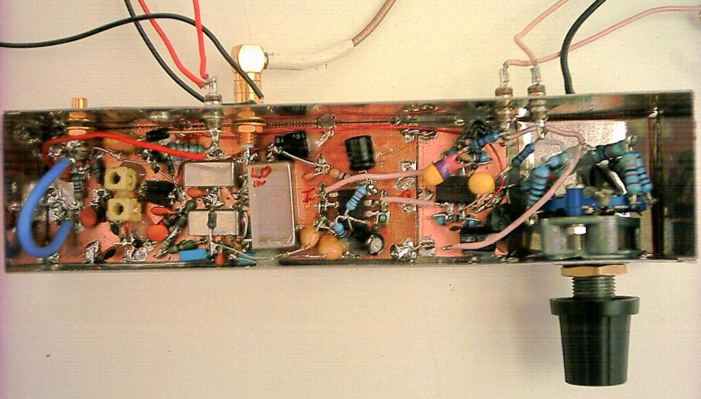
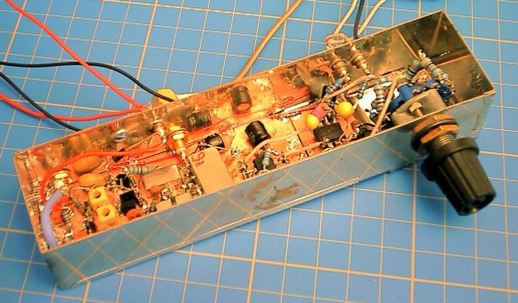
1 144MHz direct conversion receiver with I/Q outputs for use with Software Defined Radio. Overview This design is a direct conversion receiver for 144MHz with quadrature outputs for use either with a software defined radio (Reference 1) or with additional audio phasing circuitry. Quadrature outputs, generated from two 90 degree shifted local oscillators, allow SSB reception by unwanted sideband cancellation as described in Reference 2. The converter was designed with the primary aim of using it for the IF stage on microwave transverters, so a linear receiver was needed with no AGC, but a calibrated gain control to make accurate relative measurements of microwave beacons using a PC Soundcard based system for the actual level and Signal to Noise ration measurements. A straightforward gain calibration can then be used to convert these into absolute readings, making this a useful piece of test equipment for propagation studies. There is nothing inherently narrowband in the design - filtering limits the RF bandwidth to around 8MHz to eliminate strong signals from broadcast and PMR, and audio bandwidth is kept to about 20kHz, wide enough for the normal maximum soundcard sampling rate of 44100Hz. Any subsequent audio filtering for actual listening purposes is performed by the SDR software, or in separate audio processing circuitry. Operation The circuit diagram is shown in Figure 1. In the RF path two modamps, a MAR-6 and a MAR-3 amplify the RF; there is a two stage bandpass filter between them with 10MHz bandwidth. The output feeds into two SRA-1 type DBMs via a resistive splitter, with the quadrature LO signal generated using a MiniCircuits PSCQ This device guarantees less than 3 degrees phase error over 100 to 160MHz; as 144MHz is near the middle of the range we can expect a fair bit better performance here. The local oscillator is an AD9851 DDS, currently clocked at 100MHz, generating 16 to 16.67MHz followed by a X9 RF multiplier. The DDS source is not described here, but the module in a basic form is described in Reference 3. The active stages in the multiplier consist of MAR-6 modamps configured as a pair of cascaded tuned X3 stages with a final MAR-6 as amplifier/limiter, this combination forming probably the simplest tuned RF multiplier possible! (There are a couple of CW spurii generated by the DDS, but I know where they are and can ignore them). All filtering is designed to allow the LO to tune over 144 to 150MHz to cover a bit wider than the normal 2MHz narrowband segments on the microwave bands, and allow for odd LO frequencies. Multiplier output level is +10dBm drive to the quadrature hybrid. By using the internal X6 option in the AD9851 DDS Chip, the LO can be driven from a 10MHz frequency reference, producing a clock of 60MHz, but this has not been implemented yet. Hopefully spurious levels will be no worse, with none falling in the beacon bands at the lower clock frequency. The mixer outputs drive a pair of identical NE5532 opamps with a voltage gain approaching 300 (exact value a bit uncertain due to internal impedance of the mixer IF port) No clever matching, just the mixer feeding the inverting input giving 800 ohms input resistance at audio, and low pass filtering to get rid of RF leakage. The I/Q outputs feed another pair of op-amps with precisely switchable gain from 0 to 40dB in 10dB steps. Audio bandwidth is not especially tailored, but rolls off gently from about 20kHz to allow for 44100Hz sampling rate in a soundcard. The total system gain and dynamic range is based on 16 bit digitisation, and is sufficient at maximum (+40dB) to place its own thermal noise least 10dB above the quantisation noise pedestal. Strong signals
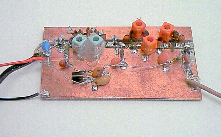
2 and extra RF gain in transverters is catered for by backing off the audio gain. For signals too strong even for this (80db S/N in 20kHz) an external (calibrated) RF attenuator can be added Construction No attempt was made to put this on a proper PCB. The converter and audio stages were built birds-nest style on a piece of unetched copper clad PCB as can be seen in Photograph 1. Plenty of decoupling and short direct wires ensure stable performance. As there is a lot of gain - particularly at audio - the whole unit was built into a tinplate box for screening Using parallel and series 1% resistors for the switchable gain stage, no especial trimming or adjustment was necessary, the traces looked well enough matched on a 'scope and as I was only after 20-25dB sideband rejection to make opposite sideband noise insignificant, tweaking wasn t necessary. 3 degrees phase error will give 25dB rejection, assuming amplitude is correct, which is about equivalent to 5% amplitude imbalance. So if I have a 'bit better' in each case the 20dB plus is easily achievable. All power rails are regulated and well filtered for operation off a portable 12V supply. The LO multiplier was made by cutting a 50 ohm microstrip line into a double sided PCB. To quickly make a 50 ohm line without etching, score two lines 2.8mm apart through the copper on the top face of the PCB for the full width, use a Stanley knife or similar making sure you penetrate the copper fully. 2.8mm width on normal 1.6mm thick fibreglass PBC gives about 50 ohms characteristic impedance. Then score two more lines about 1mm from each of these. Using a hot soldering iron, use this to soften the adhesive and with a pair of tweezers, lift up and remove the two 1mm wide strips, which will give a single 50 ohm line surrounded by copper groundplane. Drill a number of 0.8 to 1mm holes through the top ground plane to the underside and fit wire links to give a solid RF ground structure. Wire links are best fitted close to where grounding and decoupling components are connected. Cut the 50 ohm line into segments with gaps for the modamps, DC blocking capacitors and filters. Other connections around the filters are made up birds nest style. When completed and aligned, coils can be held in place with glue (a hot glue gun is a useful accessory to have around) Photograph 2 shows the completed multiplier chain. Using the downconverter. For the standalone unit for use as a receiver in the field, a simple quadrature network and loudspeaker amp can be added to make a complete receiver. A high/low pass pair of all pass networks will give 15dB sideband rejection over 400Hz to 2kHz which is good enough for listening to beacon signals on hill tops. Alternatively, look at Reference 2 for phasing type SSB networks to give an improved SSB performance. A meter driven from the audio level via a precision rectifier circuit can be added to allow quite precise signal strength measurements to be made in conjunction with the calibrated attenuator. Alternatively, take at look at the Software Defined Radio software (Ref 1) from I2PHD for another solution LO Source The DDS module as described in Ref. 3 has new PIC software, along with a rotary encoder and LCD display to give a user friendly interface. For anyone who has the original DDS board I can supply PIC software for this modification. However, the AD9850 and 9851 chips are in short supply now - they have been replaced in most cases by larger, faster, new devices in a different package. Alternatively, emulate the venerable IC202 transceiver and build a VCXO to supply the signal to the multiplier. Or use a VFO/mixer, or a synthesizer - the choice is yours!
3 Ref 1 Ref 2 RadCom series on phasing networks Feb to June Ref 3 AD9850 DDS Module RadCom, November 2000 Figure 1 Photo 1 Photo 2 Circuit Diagram RF and Audio stages. Local Oscillator multiplier
4
5
Quadrature Upconverter for Optical Comms subcarrier generation
 Quadrature Upconverter for Optical Comms subcarrier generation Andy Talbot G4JNT 2011-07-27 Basic Design Overview This source is designed for upconverting a baseband I/Q source such as from SDR transmitter
Single Conversion LF Upconverter Andy Talbot G4JNT Jan 2009
 Single Conversion LF Upconverter Andy Talbot G4JNT Jan 2009 Mark 2 Version Oct 2010, see Appendix, Page 8 This upconverter is designed to directly translate the output from a soundcard from a PC running
Alcatel White Box 24GHz Transceiver experiments and modifications
 Alcatel White Box 24GHz Transceiver experiments and modifications A set of working notes, measurements and comments PSU Need to supply : -5V up to ~ 30mA for Rx and PA modules +5.2V 1A for Rx and Tx mixer
21st Century Frequency Converters, Transverters and Radios
 21st Century Frequency Converters, Transverters and Radios Andy Talbot G4JNT www.g4jnt.com What we used to build Replace with minimum tuning, wideband integrated solutions Background The mobile phone and
Third-Method Narrowband Direct Upconverter for the LF / MF Bands
 Third-Method Narrowband Direct Upconverter for the LF / MF Bands Introduction Andy Talbot G4JNT February 2016 Previous designs for upconverters from audio generated from a soundcard to RF have been published
Technical Article A DIRECT QUADRATURE MODULATOR IC FOR 0.9 TO 2.5 GHZ WIRELESS SYSTEMS
 Introduction As wireless system designs have moved from carrier frequencies at approximately 9 MHz to wider bandwidth applications like Personal Communication System (PCS) phones at 1.8 GHz and wireless
Preliminary features of the SDR-X receiver SDR-X , PowerSDR Winrad Winrad DDS SFDR SFDR AD995 AD99 1
 Preliminary features of the SDR-X receiver The SDR-X receiver, in its full version is capable of continuously tuning the entire HF spectrum, 6m ( 50-52 MHz) band included. SSB, AM etc. demodulation, bandpass
Introduction to Receivers
 Introduction to Receivers Purpose: translate RF signals to baseband Shift frequency Amplify Filter Demodulate Why is this a challenge? Interference Large dynamic range required Many receivers must be capable
The New England Radio Discussion Society electronics course (Phase 4, cont d) Introduction to receivers
 Introduction to receivers") The New England Radio Discussion Society electronics course (Phase 4, cont d) Introduction to receivers AI2Q April 2017 REVIEW: a VFO, phase-locked loop (PLL), or direct digital synthesizer (DDS), can
The New England Radio Discussion Society electronics course (Phase 4, cont d) Introduction to receivers AI2Q April 2017 REVIEW: a VFO, phase-locked loop (PLL), or direct digital synthesizer (DDS), can
Components for modular microwave transverters. Wolf-Henning Rech DF9IC in JN48iw
 Components for modular microwave transverters Wolf-Henning Rech DF9IC in JN48iw http://www.df9ic.de Content Multiband transverter systems Filters and multiplexers PLL-disciplined oscillators Transverters
Parameter Min. Typ. Max. Units
 v4.112 Typical Applications The is ideal for: Point-to-Point and Point-to-Multi-Point Radio Military Radar, EW & ELINT Satellite Communications Functional Diagram Features General Description The is a
12kHz LIF Converter V2.43 9Mhz version
 12kHz LIF Converter V2.43 9Mhz version Please Note: This document supersedes all previously released documents and drawings on the LIF subject. This is the latest and most up-to-date document at this time.
Locked VCXOs for Stable Microwave Local Oscillators with Low Phase Noise
 Locked VCXOs for Stable Microwave Local Oscillators with Low Phase Noise Paul Wade W1GHZ 2013 w1ghz@arrl.net A good local oscillator has been a perennial problem for microwave operators. An ideal LO would
23cm PSK packet-radio RTX for 1.2Mbit/s user access Matjaz Vidmar, S53MV
 23cm PSK packet-radio RTX for 1.2Mbit/s user access --------------------------------------------------Matjaz Vidmar, S53MV 1. Why biphase PSK modulation? -----------------------------Upgrading the packet-radio
HF Amateur SSB Receiver
 HF Amateur SSB Receiver PCB Set for radio club project http://rhelectronics.net PCB for DIY HF Amateur SSB Receiver 20M The receiver is a simple syperheterodyne type with quartz crystal filter. The circuit
QUICK START GUIDE FOR DEMONSTRATION CIRCUIT 678A 40MHZ TO 900MHZ DIRECT CONVERSION QUADRATURE DEMODULATOR
 DESCRIPTION QUICK START GUIDE FOR DEMONSTRATION CIRCUIT 678A LT5517 Demonstration circuit 678A is a 40MHz to 900MHz Direct Conversion Quadrature Demodulator featuring the LT5517. The LT 5517 is a direct
A n I/Q modulator is frequently used in
 A Simplified Subharmonic I/Q Modulator This passive vector modulator uses opposite polarity diode pairs for frequency doubling to extend the range of operation By Ian Doyle M/A-COM Eurotec Operations A
HF Receivers, Part 2
 HF Receivers, Part 2 Superhet building blocks: AM, SSB/CW, FM receivers Adam Farson VA7OJ View an excellent tutorial on receivers NSARC HF Operators HF Receivers 2 1 The RF Amplifier (Preamp)! Typical
Updating KK7B, SHF,DEM or DEMI 900 and 1296 MHz. transverters
 Updating KK7B, SHF,DEM or DEMI 900 and 1296 MHz. transverters By Steve Kostro, N2CEI PREFACE: Yes, It may be hard to believe, but the original 900 and 1296 No-Tune transverter concepts have been around
MARTIN - G8JNJ ECLECTIC AETHER - ADVENTURES WITH AMATEUR RADIO
 MARTIN - G8JNJ ECLECTIC AETHER - ADVENTURES WITH AMATEUR RADIO REDUCING RTL DONGLE INTERNAL SPURII AND NOISE SIGNALS I ve recently bought quite a few RTL DVB-T RTL 2832U / Rafael Micro R820T dongles to
Locked VCXOs for Stable Microwave Local Oscillators with Low Phase Noise
 Paul Wade, W1GHZ 582 Dubray Rd, Cabot, VT 05647; w1ghz@arrl.net Locked VCXOs for Stable Microwave Local Oscillators with Low Phase Noise This Article is Reprinted from The Proceedings of Microwave Update
Module 8 Theory. dbs AM Detector Ring Modulator Receiver Chain. Functional Blocks Parameters. IRTS Region 4
 Module 8 Theory dbs AM Detector Ring Modulator Receiver Chain Functional Blocks Parameters Decibel (db) The term db or decibel is a relative unit of measurement used frequently in electronic communications
PTX-0350 RF UPCONVERTER, MHz
 PTX-0350 RF UPCONVERTER, 300 5000 MHz OPERATING MODES I/Q upconverter RF = LO + IF upconverter RF = LO - IF upconverter Synthesizer 10 MHz REFERENCE INPUT/OUTPUT EXTERNAL LOCAL OSCILLATOR INPUT I/Q BASEBAND
Low Cost Mixer for the 10.7 to 12.8 GHz Direct Broadcast Satellite Market
 Low Cost Mixer for the.7 to 12.8 GHz Direct Broadcast Satellite Market Application Note 1136 Introduction The wide bandwidth requirement in DBS satellite applications places a big performance demand on
The 144MHz Anglian 3 transverter
 The 144MHz Anglian 3 transverter A high performance 144/28MHz transverter G4DDK document issue 1 12/9/16 Introduction Anglian 3 is an update to the 144MHz Anglian 2 transverter. The Anglian 2 is no longer
RADIO RECEIVERS ECE 3103 WIRELESS COMMUNICATION SYSTEMS
 RADIO RECEIVERS ECE 3103 WIRELESS COMMUNICATION SYSTEMS FUNCTIONS OF A RADIO RECEIVER The main functions of a radio receiver are: 1. To intercept the RF signal by using the receiver antenna 2. Select the
Modification Details.
 Front end receiver modification for DRM: AKD Target Communications receiver. Model HF3. Summary. The receiver was modified and capable of receiving DRM, but performance was limited by the phase noise from
Demo board DC365A Quick Start Guide.
 August 02, 2001. Demo board DC365A Quick Start Guide. I. Introduction The DC365A demo board is intended to demonstrate the capabilities of the LT5503 RF transmitter IC. This IC incorporates a 1.2 GHz to
A 3 TO 30 MHZ HIGH-RESOLUTION SYNTHESIZER CONSISTING OF A DDS, DIVIDE-AND-MIX MODULES, AND A M/N SYNTHESIZER. Richard K. Karlquist
 A 3 TO 30 MHZ HIGH-RESOLUTION SYNTHESIZER CONSISTING OF A DDS, -AND-MIX MODULES, AND A M/N SYNTHESIZER Richard K. Karlquist Hewlett-Packard Laboratories 3500 Deer Creek Rd., MS 26M-3 Palo Alto, CA 94303-1392
THE BASICS OF RADIO SYSTEM DESIGN
 THE BASICS OF RADIO SYSTEM DESIGN Mark Hunter * Abstract This paper is intended to give an overview of the design of radio transceivers to the engineer new to the field. It is shown how the requirements
Receiver Architecture
 Receiver Architecture Receiver basics Channel selection why not at RF? BPF first or LNA first? Direct digitization of RF signal Receiver architectures Sub-sampling receiver noise problem Heterodyne receiver
Receiver Design. Prof. Tzong-Lin Wu EMC Laboratory Department of Electrical Engineering National Taiwan University 2011/2/21
 Receiver Design Prof. Tzong-Lin Wu EMC Laboratory Department of Electrical Engineering National Taiwan University 2011/2/21 MW & RF Design / Prof. T. -L. Wu 1 The receiver mush be very sensitive to -110dBm
Construction Manual 4m-Linear-Transverter XV4-15
 Construction Manual 4m-Linear-Transverter XV4-15 Holger Eckardt DF2FQ Kirchstockacherstr. 33 D-85662 Hohenbrunn 3207 Technical data exciter frequency: 21.0... 21.5 MHz RF frequency: 70.0.. 70.5 MHz supply
DEM Part Number L144-28INTCK 144 MHz Transverter Kit and complete kit
 DEM Part Number L144-28INTCK 144 MHz Transverter Kit and complete kit Power Out: Noise Figure and Gain: DC Power Requirement: 50 mw linear minimum 3.5 db NF nominal, 5 dbg maximum 12-15.5 VDC, 13.8 nominal
Feedback Loop Canceller Circuit
 Feedback Loop Canceller Circuit Bachelor Thesis Ahmad Bader Ibrahim Obeidat Supervised by Prof. Dr.-Ing. Klaus Solbach 17.11.2014 Outline: 1 Motivation 2 Circuit description 3 Tasks and objectives 4 Active
Short Term Stability Measurements of Several 10MHz Reference Sources
 Short Term Stability Measurements of Several 10MHz Reference Sources Andy Talbot G4JNT November 2013 Introduction I am fortunate in having an HP5061A Caesium Beam frequency standard that can generate a
CUSTOM INTEGRATED ASSEMBLIES
 17 CUSTOM INTEGRATED ASSEMBLIES CUSTOM INTEGRATED ASSEMBLIES Cougar offers full first-level integration capabilities, providing not just performance components but also full subsystem solutions to help
Overview of the MSA 12/30/10
 Overview of the MSA 12/30/10 Introduction The purpose of this document is to provide an overview of the capabilities and construction of the MSA to help potential builders get oriented. Much more detailed
4/30/2012. General Class Element 3 Course Presentation. Practical Circuits. Practical Circuits. Subelement G7. 2 Exam Questions, 2 Groups
 General Class Element 3 Course Presentation ti ELEMENT 3 SUB ELEMENTS General Licensing Class Subelement G7 2 Exam Questions, 2 Groups G1 Commission s Rules G2 Operating Procedures G3 Radio Wave Propagation
ALX-SSB 5 Band Filter Assembly Manual 19 November 2018
 ALX-SSB 5 Band Filter Assembly Manual 19 November 2018 Contents Theory of Operation:... 1 Figure 1... 2 Parts Included:... 4 Board Overview:... 5 Figure 2... 5 Figure 3... 5 Board Assembly:... 6 Cable
Gain Lab. Image interference during downconversion. Images in Downconversion. Course ECE 684: Microwave Metrology. Lecture Gain and TRL labs
 Gain Lab Department of Electrical and Computer Engineering University of Massachusetts, Amherst Course ECE 684: Microwave Metrology Lecture Gain and TRL labs In lab we will be constructing a downconverter.
ANALOG COMMUNICATION
 ANALOG COMMUNICATION TRAINING LAB Analog Communication Training Lab consists of six kits, one each for Modulation (ACL-01), Demodulation (ACL-02), Modulation (ACL-03), Demodulation (ACL-04), Noise power
Keysight Measuring High Impedance Sources Using the U8903B Audio Analyzer. Application Note
 Keysight Measuring High Impedance Sources Using the U8903B Audio Analyzer Application Note Introduction This note details the input impedance of the U8903B Audio Analyzer, and shows that this needs to
KWM-2/2A Transceiver THE COLLINS KWM-2/2A TRANSCEIVER
 KWM-2/2A Transceiver Click the photo to see a larger photo Click "Back" button on browser to return Courtesy of Norm - WA3KEY THE COLLINS KWM-2/2A TRANSCEIVER Unmatched for versatility, dependability and
VLF-LF Up Converter 5KHz - 500KHz. User manual. Rev HEROS technology Limited All rights reserved
 VLF-LF Up Converter 5KHz - 500KHz User manual. Rev 2016-02 Since many countries are allocating the 472 khz to 479kHZ band for experimental use by Radio Amateurs, a growing number of them as well as listeners
Automatic Tracking Filter for DDS Generator
 Riccardo Gionetti, IØFDH Via S. Bernadette, 00 Roma RM, Italy: rgionetti@virgilio.it Automatic Tracking Filter for DDS Generator Reduce spurious responses from a digital synthesizer with this filter. The
Features OBSOLETE. = +25 C, IF= 1 GHz, USB, LO = +15 dbm [1]
![Features OBSOLETE. = +25 C, IF= 1 GHz, USB, LO = +15 dbm [1]](/thumbs/82/84974573.jpg "Features OBSOLETE. = +25 C, IF= 1 GHz, USB, LO = +15 dbm [1]") v1.414 HMC141LC4 Typical Applications The HMC141LC4 is Ideal for: Point-to-Point Radio Point-to-Multi-Point Radio Test Equipment & Sensors Military End Use Functional Diagram Features Wide IF Bandwidth:
v1.414 HMC141LC4 Typical Applications The HMC141LC4 is Ideal for: Point-to-Point Radio Point-to-Multi-Point Radio Test Equipment & Sensors Military End Use Functional Diagram Features Wide IF Bandwidth:
134GHz Transverter Roger Ray G8CUB
 134GHz Transverter Roger Ray G8CUB Synthesiser 11.20 GHz x3 33.6GHz amp IF o/p 440MHz harmonic mixer Tx path Pre-amp 134GHz 20dB Simplified 134GHz transverter block diagram The idea for a 134Ghz system
Introduction Introduction to radio frequencies p. 3 What are the 'radio frequencies'? p. 3 Why are radio frequencies different? p.
 Foreword p. xi Preface p. xiii Introduction Introduction to radio frequencies p. 3 What are the 'radio frequencies'? p. 3 Why are radio frequencies different? p. 3 What this book covers p. 3 Signals and
JUMA-TRX2 DDS / Control Board description OH2NLT
 JUMA-TRX2 DDS / Control Board description OH2NLT 22.08.2007 General Key functions of the JUMA-TRX2 DDS / Control board are: - provide user interface functions with LCD display, buttons, potentiometers
4 GHz to 8.5 GHz, GaAs, MMIC, I/Q Mixer HMC525ALC4
 Data Sheet FEATURES Passive: no dc bias required Conversion loss: 8 db (typical) Input IP3: 2 dbm (typical) LO to RF isolation: 47 db (typical) IF frequency range: dc to 3. GHz RoHS compliant, 24-terminal,
Dual Band Filter Assembly Manual
 Dual Band Filter Assembly Manual 12 January 2018 Rev D Version Theory of Operation: The purpose of a Bandpass Filter is to filter out or reject all unwanted signals. The original KN-Q7A Receive Filter
Construction Manual 6m-Linear-Transverter XV6/10
 Construction Manual 6m-Linear-Transverter XV6/10 Holger Eckardt DF2FQ Kirchstockacherstr. 33 D-85662 Hohenbrunn 2606 Technical data exciter frequency: 28... 30 MHz RF frequency: 50... 52 MHz supply voltage:
Application Note Receivers MLX71120/21 With LNA1-SAW-LNA2 configuration
 Designing with MLX71120 and MLX71121 receivers using a SAW filter between LNA1 and LNA2 Scope Many receiver applications, especially those for automotive keyless entry systems require good sensitivity
FM Radio Transmitter & Receiver Modules
 Features Miniature SIL package Fully shielded Data rates up to 128kbits/sec Range up to 300 metres Single supply voltage Industry pin compatible T5-434 Temp range -20 C to +55 C No adjustable components
Low voltage high performance mixer FM IF system
 DESCRIPTION The is a low voltage high performance monolithic FM IF system incorporating a mixer/oscillator, two limiting intermediate frequency amplifiers, quadrature detector, logarithmic received signal
21 GHz to 27 GHz, GaAs, MMIC, I/Q Upconverter HMC815B
 Data Sheet 1 GHz to 7 GHz, GaAs, MMIC, I/Q Upconverter HMC1B FEATURES Conversion gain: db typical Sideband rejection: dbc typical OP1dB compression: dbm typical OIP3: 7 dbm typical LO to RF isolation:
ADI 2006 RF Seminar. Chapter II RF/IF Components and Specifications for Receivers
 ADI 2006 RF Seminar Chapter II RF/IF Components and Specifications for Receivers 1 RF/IF Components and Specifications for Receivers Fixed Gain and Variable Gain Amplifiers IQ Demodulators Analog-to-Digital
Phase Noise and Tuning Speed Optimization of a MHz Hybrid DDS-PLL Synthesizer with milli Hertz Resolution
 Phase Noise and Tuning Speed Optimization of a 5-500 MHz Hybrid DDS-PLL Synthesizer with milli Hertz Resolution BRECHT CLAERHOUT, JAN VANDEWEGE Department of Information Technology (INTEC) University of
SC5307A/SC5308A 100 khz to 6 GHz RF Downconverter. Datasheet SignalCore, Inc.
 SC5307A/SC5308A 100 khz to 6 GHz RF Downconverter Datasheet 2017 SignalCore, Inc. support@signalcore.com P RODUCT S PECIFICATIONS Definition of Terms The following terms are used throughout this datasheet
LM13600 Dual Operational Transconductance Amplifiers with Linearizing Diodes and Buffers
 LM13600 Dual Operational Transconductance Amplifiers with Linearizing Diodes and Buffers General Description The LM13600 series consists of two current controlled transconductance amplifiers each with
SC5407A/SC5408A 100 khz to 6 GHz RF Upconverter. Datasheet. Rev SignalCore, Inc.
 SC5407A/SC5408A 100 khz to 6 GHz RF Upconverter Datasheet Rev 1.2 2017 SignalCore, Inc. support@signalcore.com P R O D U C T S P E C I F I C A T I O N S Definition of Terms The following terms are used
5.5 GHz to 8.6 GHz, GaAs, MMIC, I/Q Upconverter HMC6505A
 Data Sheet FEATURES Conversion gain: db typical Sideband rejection: dbc typical Output P1dB compression at maximum gain: dbm typical Output IP3 at maximum gain: dbm typical LO to RF isolation: db typical
Modification of Alcatel 9400UX Synthesisers By Roger Ray G8CUB - Updated
 Modification of Alcatel 9400UX Synthesisers By Roger Ray G8CUB - Updated Many Alcatel Outdoor Units have been purchased, for conversion to 24GHz. For some reason the synthesiser local oscillator is not
24-bit Step Size, Resolution 3 Hz typ Exact Frequency Mode Built-in Digital Self Test 40 Lead 6x6mm SMT Package: 36mm 2. Phased Array Applications
 FRACTIONAL-N PLL WITH INTEGRATED VCO, 80-80 MHz Features RF Bandwidth: 80 to 80 MHz Ultra Low Phase Noise -110 dbc/hz in Band Typ. Figure of Merit (FOM) -22 dbc < 180 fs RMS Jitter 24-bit Step Size, Resolution
6 GHz to 10 GHz, GaAs, MMIC, I/Q Mixer HMC520A
 11 7 8 9 FEATURES Radio frequency (RF) range: 6 GHz to 1 GHz Local oscillator (LO) input frequency range: 6 GHz to 1 GHz Conversion loss: 8 db typical at 6 GHz to 1 GHz Image rejection: 23 dbc typical
PRC 320 Modifications Martin Ehrenfried G8JNJ
 PRC 320 Modifications Martin Ehrenfried G8JNJ I have deliberately not given specific cut wire here instructions, as the construction of the PRC320 does seem to vary considerably. This especially applies
G0CWA Mk2 RTL SDR RADIO SEPTEMBER 2012
 G0CWA Mk2 RTL SDR RADIO SEPTEMBER 2012 For use with RTL2832U-based DVB-T USB dongle with the Elonics E4000 tuner Hi, welcome to my latest project my improved version of my SDR radio. This is based on my
Handbook / Kit. DB 6 NT 5,7 GHz Transverter MK DB 6 NT
 Handbook / Kit DB 6 NT 5,7 GHz Transverter MK2 4.2003 DB 6 NT 5,7 GHz Transverter MK2 DB6NT 4.2003 3. Generation Indroduction In 1977 the DUBUS magazine published the first 5,7GHz SSB transverter which
Albert F. Peter AC8GY Aug. 12, 2010
 Albert F. Peter AC8GY Aug. 12, 2010 Software-defined not software-controlled radio Most of the complex signal handling uses DSP User interface through the computer Usually some form of direct conversion
OBSOLETE HMC915LP4E. GaAs MMIC MIXER w/ INTEGRATED LO AMPLIFIER, GHz. Typical Applications. Features. Functional Diagram. General Description
 v1.5 LO AMPLIFIER,.5-2.7 GHz Typical Applications The is ideal for: PCS / 3G Infrastructure Base Stations & Repeaters WiMAX & WiBro ISM & Fixed Wireless Functional Diagram Features Input IP3: +28 dbm Low
8.5 GHz to 13.5 GHz, GaAs, MMIC, I/Q Mixer HMC521ALC4
 11 7 8 9 FEATURES Downconverter, 8. GHz to 13. GHz Conversion loss: 9 db typical Image rejection: 27. dbc typical LO to RF isolation: 39 db typical Input IP3: 16 dbm typical Wide IF bandwidth: dc to 3.
SPECIFICATIONS: Subcarrier Frequency 5.5MHz adjustable, FM Modulated +/- 50KHz. 2nd 11MHz >40dB down from 5.5MHz
 Mini-kits AUDIO / SUBCARRIER KIT EME75 Version4 SPECIFICATIONS: Subcarrier Frequency 5.5MHz adjustable, FM Modulated +/- 50KHz Subcarrier Output 1.5v p-p Output @ 5.5MHz DESCRIPTION & FEATURES: The Notes
An Arduino DCR-SDR Project: Part 1
 First published in the May-Jun 2015 issue of The Canadian Amateur An Arduino DCR-SDR Project: Part 1 INTRODUCTION In this part, we ll build a simple direct conversion receiver (DCR) software defined radio
ECE 203 ELECTRIC CIRCUITS AND SYSTEMS LABORATORY SPRING No labs meet this week. Course introduction & lab safety
 ECE 203 ELECTRIC CIRCUITS AND SYSTEMS LABORATORY SPRING 2019 Week of Jan. 7 Jan. 14 Jan. 21 Jan. 28 Feb. 4 Feb. 11 Feb. 18 Feb. 25 Mar. 4 Mar. 11 Mar. 18 Mar. 25 Apr. 1 Apr. 8 Apr. 15 Topic No labs meet
Low voltage LNA, mixer and VCO 1GHz
 DESCRIPTION The is a combined RF amplifier, VCO with tracking bandpass filter and mixer designed for high-performance low-power communication systems from 800-1200MHz. The low-noise preamplifier has a
Data Sheet SC5317 & SC5318A. 6 GHz to 26.5 GHz RF Downconverter SignalCore, Inc. All Rights Reserved
 Data Sheet SC5317 & SC5318A 6 GHz to 26.5 GHz RF Downconverter www.signalcore.com 2018 SignalCore, Inc. All Rights Reserved Definition of Terms 1 Table of Contents 1. Definition of Terms... 2 2. Description...
Low-voltage mixer FM IF system
 DESCRIPTION The is a low-voltage monolithic FM IF system incorporating a mixer/oscillator, two limiting intermediate frequency amplifiers, quadrature detector, logarithmic received signal strength indicator
N3ZI Kits General Coverage Receiver, Assembly & Operations Manual (For Jun 2011 PCB ) Version 3.33, Jan 2012
 Version 3.33, Jan 2012") N3ZI Kits General Coverage Receiver, Assembly & Operations Manual (For Jun 2011 PCB ) Version 3.33, Jan 2012 Thank you for purchasing my general coverage receiver kit. You can use the photo above as a
N3ZI Kits General Coverage Receiver, Assembly & Operations Manual (For Jun 2011 PCB ) Version 3.33, Jan 2012 Thank you for purchasing my general coverage receiver kit. You can use the photo above as a
2-Tone Generator For 145Mhz
 Wolfgang Schneider, DJ8ES 2-Tone Generator For 145Mhz An RF amplifier stage is not only classified by amplification, which is as high as possible, and thus by its maximum output. What is frequently not
6.976 High Speed Communication Circuits and Systems Lecture 20 Performance Measures of Wireless Communication
 6.976 High Speed Communication Circuits and Systems Lecture 20 Performance Measures of Wireless Communication Michael Perrott Massachusetts Institute of Technology Copyright 2003 by Michael H. Perrott
PN9000 PULSED CARRIER MEASUREMENTS
 The specialist of Phase noise Measurements PN9000 PULSED CARRIER MEASUREMENTS Carrier frequency: 2.7 GHz - PRF: 5 khz Duty cycle: 1% Page 1 / 12 Introduction When measuring a pulse modulated signal the
VLF-LF-MF Up Converter
 VLF-LF-MF Up Converter 5kHz-500kHz 3.5MHz-4MHz model 350 4MHz-4.5MHz model 400 User manual. Rev 2018-01 Since many countries are allocating the 472 khz to 479kHZ band for experimental use by Radio Amateurs,
Linrad: New Possibilities for the Communications Experimenter, Part 2
 Linrad: New Possibilities for the Communications Experimenter, Part 2 From the Analog World into the Digital: How do we get the desired signal from RF to the sound card? By Leif Åsbrink, SM5BSZ Linrad
IC-R8500 Test Report. By Adam Farson VA7OJ/AB4OJ
 IC-R8500 Test Report By Adam Farson VA7OJ/AB4OJ Iss. 1, Dec. 14, 2015. Figure 1: The Icom IC-R8500. Introduction: This report presents results of an RF lab test suite performed on the IC- R8500 receiver.
Generating MSK144 directly for Beacons and Test Sources.
 Generating MSK144 directly for Beacons and Test Sources. Overview Andy Talbot G4JNT December 2016 MSK144 is a high speed data mode introduced into WSJT-X to replace FSK441 for meteor scatter (MS) and other
MK LOW PHASE NOISE T1/E1 CLOCK GENERATOR. Features. Description. Block Diagram DATASHEET. Pullable Crystal
 DATASHEET LOW PHASE NOISE T1/E1 CLOCK ENERATOR MK1581-01 Description The MK1581-01 provides synchronization and timing control for T1 and E1 based network access or multitrunk telecommunication systems.
HT-1A Dual Band CW QRP Transceiver. Kit Building Instructions
 HT-A Dual Band CW QRP Transceiver Kit Building Instructions Rev B, July 8, 08 Designed by BD4RG Exclusively distributed by CRKITS.COM and its worldwide distributors Join the group http://groups.io/g/crkits
Ten-Tec Orion Synthesizer - Design Summary. Abstract
 Ten-Tec Orion Synthesizer - Design Summary Lee Jones 7/21/04 Abstract Design details of the low phase noise, synthesized, 1 st local oscillator of the Ten-Tec model 565 Orion transceiver are presented.
Technician License Course Chapter 3 Types of Radios and Radio Circuits. Module 7
 Technician License Course Chapter 3 Types of Radios and Radio Circuits Module 7 Radio Block Diagrams Radio Circuits can be shown as functional blocks connected together. Knowing the description of common
A GOOD REGENERATIVE RECEIVER WITH SIMPLE FINE TUNING (2008)
") A GOOD REGENERATIVE RECEIVER WITH SIMPLE FINE TUNING (2008) A good SSB-CW-AM regenerative receiver with a fine tuning by moving the wooden stick with a grounded piece of PCB towards the coil. A good regenerative
A GOOD REGENERATIVE RECEIVER WITH SIMPLE FINE TUNING (2008) A good SSB-CW-AM regenerative receiver with a fine tuning by moving the wooden stick with a grounded piece of PCB towards the coil. A good regenerative
TestData Summary of 5.2GHz WLAN Direct Conversion RF Transceiver Board
 Page 1 of 16 ========================================================================================= TestData Summary of 5.2GHz WLAN Direct Conversion RF Transceiver Board =========================================================================================
TDA7000 for narrowband FM reception
 TDA7 for narrowband FM reception Author: Author: W.V. Dooremolen INTRODUCTION Today s cordless telephone sets make use of duplex communication with carrier frequencies of about.7mhz and 49MHz. In the base
= +25 C, IF = 2350 MHz, LO = +4 dbm, VDLO1, 2 = +3V, IDLO = 150 ma, VDRF = +3V, IDRF = 200mA, USB [1][2] Parameter Min. Typ. Max.
![= +25 C, IF = 2350 MHz, LO = +4 dbm, VDLO1, 2 = +3V, IDLO = 150 ma, VDRF = +3V, IDRF = 200mA, USB [1][2] Parameter Min. Typ. Max.](/thumbs/86/93858186.jpg "= +25 C, IF = 2350 MHz, LO = +4 dbm, VDLO1, 2 = +3V, IDLO = 150 ma, VDRF = +3V, IDRF = 200mA, USB [1][2] Parameter Min. Typ. Max.") v1.31 HMC677ALC5A 37 - GHz Typical Applications The HMC677ALC5A is ideal for: Point-to-Point and Point-to-Multi-Point Radio Military Radar, EW & ELINT Satellite Communications Sensors Functional Diagram
v1.31 HMC677ALC5A 37 - GHz Typical Applications The HMC677ALC5A is ideal for: Point-to-Point and Point-to-Multi-Point Radio Military Radar, EW & ELINT Satellite Communications Sensors Functional Diagram
14 MHz Single Side Band Receiver
 EPFL - LEG Laboratoires à options 8 ème semestre MHz Single Side Band Receiver. Objectives. The objective of this work is to calculate and adjust the key elements of an Upper Side Band Receiver in the
PART MAX2605EUT-T MAX2606EUT-T MAX2607EUT-T MAX2608EUT-T MAX2609EUT-T TOP VIEW IND GND. Maxim Integrated Products 1
 19-1673; Rev 0a; 4/02 EVALUATION KIT MANUAL AVAILABLE 45MHz to 650MHz, Integrated IF General Description The are compact, high-performance intermediate-frequency (IF) voltage-controlled oscillators (VCOs)
Keywords: GPS, receiver, GPS receiver, MAX2769, 2769, 1575MHz, Integrated GPS Receiver, Global Positioning System
 Maxim > Design Support > Technical Documents > User Guides > APP 3910 Keywords: GPS, receiver, GPS receiver, MAX2769, 2769, 1575MHz, Integrated GPS Receiver, Global Positioning System USER GUIDE 3910 User's
CW Modulator Using Pin Diodes
 Wolfgang Schneider, DJ8ES CW Modulator Using Pin Diodes This article describes a CW modulator for radio applications which is simple and uncomplicated from the rf technology point of view. The call sign
High performance low power mixer FM IF system
 DESCRIPTION The is a high performance monolithic low-power FM IF system incorporating a mixer/oscillator, two limiting intermediate frequency amplifiers, quadrature detector, muting, logarithmic received
24-bit Step Size, Resolution 3 Hz typ Exact Frequency Mode Built-in Digital Self Test 40 Lead 6x6 mm SMT Package: 36 mm 2. Phased Array Applications
 Features Tri-band RF Bandwidth: Ultra Low Phase Noise -105 dbc/hz in Band Typ. Figure of Merit (FOM) -227 dbc/hz < 180 fs RMS Jitter 24-bit Step Size, Resolution 3 Hz typ Exact Frequency Mode Built-in