SmartPTT PLUS 9.1. Radioserver Configurator User Guide
|
|
|
- Eugene Burns
- 5 years ago
- Views:
Transcription


1 Radioserver Configurator User Guide November 2016
2 Table of contents SmartPTT Radioserver Configurator 5 Settings 5 Radioserver 5 Redundant Radio Server 8 Licenses 14 Services 20 ARS 20 GPS 22 TMS 23 Telemetry 24 Subscriber Blacklist 24 Gateway 27 SMS Gateway 34 File Receive 40 Add-on Modules 45 Tallysman 45 Indoor Tracking 47 Event Log 55 Settings 55 Automatic Database Backup 55 Phone Calls 61 Telephone Interconnect 61 Bridging 72 Multigroups 72 Voice Notifications 74 Clients Connection 76 Web Service 76 Third-Party Applications 76 Monitoring 78 2
3 Settings 78 Automatic Database Backup 78 SNMP Service 78 Profiles 82 Subscriber Groups 87 Metadata 88 Subscribers 89 Automatic Database Backup 90 Networks 91 Control Stations 91 How to Configure Control Station Channels 100 How to Configure Control Station Talkgroups 101 How to Configure Control Station Audio Settings 102 Connect Plus 103 How to Configure Connect Plus 104 XRC Controller 106 XRT Gateway 107 Control Stations 110 Security Settings in Connect Plus 112 NAI Systems 120 How to Configure NAI System 122 How to Configure NAI Slots 122 How to Configure NAI Talkgroups 122 Security Settings 122 How to Configure Control Stations 122 Audio Settings 122 How to configure local slots 122 DDMS Settings 122 MNIS Data Gateway 122 MNIS and DDMS service settings 122 Capacity Max 163 3
4 How to Configure Capacity Max 165 Trunking Controller 170 MNIS Data Gateway 175 MNIS VRC Gateway 182 Talkgroups 187 Security Settings 188 SIP/RTP Interfaces 200 SIP/RTP gateway 202 SmartPTT Radioservers 203 Client List 232 Rules 234 Activity 238 Network Configuration 239 Log 247 Export/Import Settings 248 Statistics 250 4

5 SmartPTT Radioserver Configurator Settings In this tab you can configure the general settings of SmartPTT Radioserver: Radioserver, Licenses, Radio network services, Add-on Modules, Profiles, Subscriber groups, Metadata. Radioserver To set up the radioserver, click Radio Server in the left list of the SmartPTT Radioserver Configurator window. At that, the Radio Server window opens. 5
6 Server Role: Sets the radioserver role: Primary or Redundant. Primary radioserver can have only one redundant radioserver and vise versa. To configure the redundant radioserver settings, see the Redundant Radio Server section. Name: Radioserver alias. You cannot type more than 20 characters into this field. Interface and Port: Radioserver IP address, i.e. the IP address of the PC where the radioserver is installed. Default port is Note: If the specified port is occupied, you will see the warning icon next to the input field. Hover the mouse over the icon to see where the port is being used. Authentication: Authentication parameters required for connection to the radioserver. Select No to set anonymous authentication. Select Windows to set Windows authentication. Note: If Windows is selected, to connect, the dispatcher must use the user name and password of the account where the radioserver service was started. VoIP Listen Port: Number of a UDP port for receiving voice data from the dispatcher. Block option: Allows selecting the way how to block a radio. When Radio Disable is applied, radioserver sends the Radio Disable command to block the radio. The Deny Channel option denies the subscriber radio to work on the given channel. Note: The Deny Channel option is applicable only to IP Site Connect (direct IP connection) or NAI based configurations. Note: When the Block Radio command is sent from one radio unit to another, the radio will be blocked, even if Deny Channel is selected. Limit Radios to Service: Allows to manage the number of radios allowed in the network. Here the user can specify which radios are to be controlled by the system and which are not. o Enabled: Select to make this functionality active. o Allowed Radio Numbers: Enter ID's of the radios which are to be controlled by the system. Warning! All the radios whose ID's were not specified will be ignored by SmartPTT system. Process priority: Allows selecting the priority that the system associates with a process. By setting this parameter you can speed up or slow down SmartPTT performance. The highest possible 6

7 priority is Real time. Use it wisely! It may cause malfunctioning of the whole system. We recommend to use the Normal priority. Language: Allows selecting languages of the user interface of the SmartPTT Radioserver Configurator application. You can save changes made by clicking Save. If you want to cancel changes made, click Restore. All the changes made after the last save will be restored. To exit SmartPTT Radioserver Configurator, click Close. To view help, click Help. The radioserver is implemented as Windows service SmartPTT Radio Service. To enable saved changes you must restart the service. Service is managed using the following buttons: Start, Stop and Restart,. 7

8 Redundant Radio Server To set up the redundant radioserver, perform the following actions: 1. Click Radio Server in the left list of the SmartPTT Radioserver Configurator window. In the Radio Server window in the Server Role field select Redundant. At that the Redundant Radio Server item appears in the left list of the SmartPTT Radioserver Configurator window. 8

9 2. Click Redundant Radio Server and in the Redundant Radio Server Settings window configure the required settings. Redundancy: The redundant server can be useful in case of the primary server breakdown. Switching between the servers is made automatically. In the Network Configuration tab you can set up automatic radioserver redundancy error notifications. Attention! The redundant server is activated only on the condition that the last connection to the primary server was no later than 31 days ago. o Primary server address (host:port): The primary radioserver IP address and port. o Connection timeout (s): Time interval that starts ticking as soon as the primary server is down. If the primary server has not recovered within the specified time interval, the redundant server takes over. The least possible value is 20 seconds. o Synchronize with primary radio server: Enabling/disabling the auto synchronization of the redundant server with the primary one. Note: When Synchronize with primary server is selected, the Settings, Networks, Network Configuration and Rules tabs are unavailable for editing except for the following parameters: Server Role and 9

10 Language (Settings > Radio Server), redundant radioserver settings (Settings > Redundant Radio Server) and alarm notification settings (Network Configuration > Radio Server). o Copy Settings: Copies the primary radioserver settings to the redundant one. Note: If Synchronize with primary server is selected, the primary radioserver settings will be copied in accordance with Correspondence table. Correspondence table: Table of value and parameter replacement rules. It is available for editing only if Synchronize with primary server is selected. o Change Type: Data type to be changed: Value or Parameter. o Value/Parameter: The numerical value or the parameter name to be changed on the redundant radioserver. o Redundant Radio Server Value: The value assigned to the redundant server. To replace a certain value of all primary server parameters and add it to Correspondence table, click Add Value. In Correspondence table in the Value/Parameter field enter the value to be replaced and in the Redundant Radio Server Value field enter the replacing value. To replace a certain parameter for the redundant server and add it to Correspondence table, click Add Parameter. At that the Parameter Overriding window opens. To edit a certain value or parameter in Correspondence table, double-click the required table row and make necessary changes. To delete a value or parameter from Correspondence table, click the required value or parameter and click Delete. 10

11 To change a certain parameter value for the redundant server, perform the following actions in the Parameter Overriding window: 1. In the setting tree of the Settings or Networks tab select the required item. Note: The structure of the Settings and Networks tabs corresponds to the structure of the same SmartPTT Radioserver Configurator tabs. 11


12 2. In the Parameter drop-down list select the required parameter. 3. In the Value area either enter the value, select it in the drop-down list or select/unselect the checkbox. 4. To add the changed parameter to Correspondence table, click Add. 5. Having added all the required parameters click Finish. Attention! You must always override the Peer ID parameter for the following network topologies: NAI IP Site Connect, NAI Capacity Plus and NAI Linked Capacity Plus. The primary and redundant servers must have different Peer IDs in the mentioned topologies. 12
13 How to Set up the Redundancy in SmartPTT Radioserver Configurator and SmartPTT Dispatcher. To make the redundant server work correctly, perform the following actions: 1. Take two radioservers and define their roles: Redundant or Primary. In the settings of the redundant server enter the IP address of the primary radioserver. A primary server can be backed up only with one redundant server. If needed, configure the synchronization of the redundant server with the primary one. 2. Make sure that both radioservers are up and running. 3. Add both radioservers into the dispatch console (Settings > Radioservers). Make them both active. 4. Check that you can see both radioservers online in the Radio Fleet panel of SmartPTT Dispatcher. 13

14 Licenses In the Licenses menu you can see the services which are available to you in the SmartPTT software and install a new license if needed. Availability of the services is regulated by the license file. It contains licenses permissions to use the particular number of particular services. They'll be Those licenses are being called here as services. At the fresh start the SmartPTT software generates demo license file which works for a small period of time. You cannot extent its activity period and you should obtain a regular license file. Regular license file binds to the hardware of the primary radioserver PC or redundant radioserver PC. Hardware ID (HID) is required for the binding. To obtain hardware ID via SmartPTT Radioserver Configurator: 1. Run SmartPTT Radioserver Configurator. 14
15 2. In the Settings tab click Licenses. 3. Click the Collect button in the Activation area of the Licenses window. The code which appears in the Hardware ID field is the hardware ID. 4. Click Copy to copy the hardware ID to the clipboard. To obtain hardware ID without SmartPTT Radioserver Configurator, please, refer to the following article on the SmartPTT Technical Support Center website. When you get the license file, you should install it. To do this: 1. Run SmartPTT Radioserver Configurator. 2. In the Settings tab click Licenses. 3. Click the Change License button. 15

16 4. Open the received license file. The License Installation window will appear. Installing the right license file 16


17 5. Check the information in the License Installation window. Pay attention to the table to check if you have all the services you need. Note. If the license does not match the product or the hardware, Licensed to text will be red and the services table will be empty. Installing the w rong license file 6. To accept the license click Apply. To cancel the license installation click Cancel. 7. Click OK in the notification window, save changes and restart the radioserver. After the license installation in the Licenses window the available services will appear as they were in the License Installation window. 17


18 Different services may have different expiration date. When the service is expired, it will be written red in the table. When the expiration data approaches, you will start to get notifications at the start of SmartPTT Radioserver Configurator: 18

19 In addition, yellow triangle will appear near the dates, notifying about the approaching of the expiration date. You cannot update or upgrade to the SmartPTT software released later of the expiration date of annual support. Nevertheless, your current software will continue to operate without any limitations until the licensed services are not expired. You could also be provided with the limited technical support for the SmartPTT software. To use the newest version of the SmartPTT software with all new features, please, renew the annual support. 19

20 Services ARS ARS or registration service provides information on the availability of radio subscribers in the radio network. To set up the registration service parameters, click ARS in the list in the left area of the SmartPTT Radioserver Configurator window. At that, a new window appears on the right. Active: Select to enable the service. Use Radio Check: This setting defines the mechanism used for checking radio subscriber presence in the network. If selected, the system uses the Radio Check command. This option was implemented for radios that do not support ARS. Radio Inactivity Timeout, s: Time period, after which the radio that did not display any activity becomes potentially absent. In this case the system includes this radio into a special presence check process. Note: Radio activity includes the following events: GPS location, telemetry signal, text message or voice call. Generally, a radio can be sent 5 presence check requests successively with a 30-second interval. This parameter is called Individual Minimum Check Interval and equals 30s; it can't be changed in SmartPTT Radioserver Configurator. This parameter sets the interval between presence check requests sent to one radio. Therefore, it can be increased depending on the number of radios to check. If the radio does not respond to the presence check requests and does not display any activity, it will acquire the Offline status after the 5th unsuccessful presence check request. Global Minimum Request Interval, ms sets the minimum interval between presence check requests sent to all inactive radios in all networks. Instead of sending presence check requests to all inactive radios at one time, the system puts them on a queue and sends one presence check request to one radio at a time with the interval set in the Global Minimum Request Interval field. This method allows us to eliminate the risk of sending too many 20
21 presence check requests at one time, thus removing traffic overload on the channel and spreading network load evenly. Example There are three radios active till 10:00:00 and 10:00:02 (see pic. below). Then, for the following 600s they do not display any activity. So, the radio activity timeout for Radios 1 and 2 runs out at 10:10:00 and for Radio 3 at 10:10:02. When it happens, the system creates a pool of inactive radios. The system puts the radios on a queue and starts sending presence check requests with the interval set in the Global Minimum Request Interval field. Radio 2 responds to the presence check request and is no longer regarded as potentially offline. Radios 1 and 3 do not respond to the presence check request and do not display any activity, so the system sends another request in 30s to each radio. After the 5th presence check request, the radios get the Offline status. Automatic update of registration, h: If selected, the radio will send its ARS data to server at specified intervals. Note: We recommend to specify the automatic registration update interval larger than the radio inactivity timeout interval. 21

22 GPS GPS or location service provides coordinates of radio subscribers with a GPS receiver so you can determine their current location. To set up location service parameters, click GPS in the list in the left area of the SmartPTT Radioserver Configurator window. At that, the following window opens. Active: Select to activate the location service. Minimum location update interval, s: Minimum update time interval. If the time interval specified by the dispatcher is less than Minimum location update interval, the new value set by the dispatcher will be ignored, and subscriber location will be updated within Minimum location update interval. Minimum Request Interval, s: The minimum interval between GPS requests sent to the radios within one network. The requests can be sent automatically or initiated by the dispatcher. This method allows us to eliminate the risk of sending too many GPS requests at one time, thus removing traffic overload on the channel and spreading network load evenly. 22

23 Radio Inactivity Timeout, s: Time period, after which the radio that did not send GPS becomes potentially absent. In this case the radio receives a location update request. system includes this radio into a special presence check process. The Get Subscriber Location for Following Groups list allows you to specify location update time interval per subscriber group added in SmartPTT Radioserver Configurator under Subscriber Groups. If Allow Dispatchers to Amend Location Update Time Interval is selected, dispatchers can reduce the location update time interval configured in the table above. However, if the time interval specified by the dispatcher is less than Minimum location update interval, the new value set by the dispatcher will be ignored, and subscriber location will be updated within Minimum location update interval. If Allow Dispatchers to Amend Location Update Time Interval is not selected, dispatchers won t be able to change the time interval for location update, and location will be updated within the time interval set in the table per each group. Warning! If "Allow Dispatchers to Amend Location Update Time Interval" is not selected and there are no subscriber groups in the table, the dispatcher won't receive any subscriber location data. TMS TMS or text messaging service is used to exchange text messages between radio subscribers and SmartPTT Dispatcher. To set up the messaging service parameters, click TMS in the setting tree of the SmartPTT Radioserver Configurator window. At that, the TMS window opens. To enable the messaging service, select the Active check box. 23

24 Telemetry The telemetry service is used for transmission and processing of telemetry signals between SmartPTT Dispatcher and radio subscribers. To set up the telemetry service parameters, click Telemetry in the list in the left area of the SmartPTT Radioserver Configurator window. At that, the Telemetry Service window opens. To enable the telemetry service, select the Active check box. Subscriber Blacklist Subscriber blacklist allows managing the number of available radio subscribers and operators in the network. To create a blacklist, first it is necessary to create subscriber groups. We will need these to form a blacklist. To add a subscriber group, click Subscriber Groups in the setting tree of SmartPTT Radioserver Configurator. At that, the Subscriber Groups window opens on the right. Group Name: Any name of a subscriber group. Subscribers: The list of radio IDs that are to be included in the created group. 24

25 To configure blacklist parameters, click Subscriber Blacklist in the setting tree of SmartPTT Radioserver Configurator. At that, the following window opens. Active: Select to enable the subscriber blacklist service. Note: Subscriber Blacklist allows not only blocking certain radios, but also creating the so-called "whitelist" of radios that are allowed in the radio network. In the latter case all other radios, that is not included in the whitelist, will be blocked. To block certain groups of subscribers, choose Deny and select groups that are not permitted to communicate in MOTOTRBO network. To allow certain groups of subscribers to communicate in MOTOTRBO network, that is to create a whitelist, select Allow and mark those groups that will be available in radio network when all other radios are blocked. Blocking Retry Interval, sec: Sets a minimum time period for sending a command to block the radio added in the blacklist. Blocking Retries: Number of retries to send the Block command to the radio before confirmation comes. 25
26 To save changes, click Save and then click Restart to restart SmartPTT Radioserver. If a radio is in the blacklist and MOTORBO control station is used (MOTOTRBO control station, Capacity Plus system), then the radio will be completely unavailable. When the radio is unavailable, some actions are still available: Monitoring, Radio Check and Radio Unblocking. The dispatcher can remove the block from the radio by sending the "Unblock" command. To enable the radio without dispatcher's help, just read the codeplug of the radio in MOTOTRBO Customer Programming Software (called MOTOTRBO CPS) and then write the settings to the codeplug. To be able to process the Radio Disable command, the radio must have the Radio Disable Decode parameter selected in the codeplug. You can find it in MOTOTRBO CPS, in the Signaling Systems section. If Radio Disable Decode is not selected, the radio can't be blocked even if it is in the blacklist. When direct IP connection is used (for example, IP Site Connect) in MOTOTRBO network, radio blocking allows to block the channel only. At that, "Channel Denied" is displayed on the radio screen. The radio can change the channel and resume its operation. To enable the blocked channel, the dispatcher should send the "Unblock" command to the radio. To enable the radio without dispatcher's help, delete the blocked channel and create the channel equal to the deleted one. 26

27 Gateway gateway provides the ability to exchange digital messages between users and MOTOTRBO radio network subscribers. The following scheme displays how it is done. To be able to exchange messages between radio subscribers and users you need: 1. Create and configure account. 2. Configure the radioserver. 27
28 Create and Configure Account First of all, create your account, if you do not have one. This section describes how to do it as well as how to configure it properly. 1. Create your account. You can use your corporate server or any other server. In this example we are using gmail.com. 2. In the settings of the newly created account specify all the necessary parameters. 3. In the settings of the account in the Forwarding and POP/IMAP tab select the following items: 1) Enable POP for all (even mail that has already been downloaded). 2) Enable IMAP. 3) Save changes. 4. If you have an client (for example, Microsoft Outlook), for the outgoing messages you need the following settings: 1) Use plain text as message format. 2) Use Unicode (UTF-8) for outgoing images (with Base64 encoder). 28

29 Configure SmartPTT Radioserver Settings The radioserver configuration includes the following steps: 1. Configure gateway (activate gateway, choose the direction of text message sending). 2. Setup POP3/IMAP4 protocols for sending text messages. Gateway Configuration Select Gateway in SmartPTT Radioserver Configurator. Select the Active check box to enable the gateway service. Forward Messages to Select to enable message forwarding from radio subscribers to the addresses specified in the Recipients list. Note: When a radio subscriber sends a text message to another radio subscriber, all users whose s are given in the Recipients list will receive 1 or 2 text messages. The first one with the confirmation that the message was sent and the second with the confirmation on delivery. 29
30 Sender Name: Specify domain name, in the name of which all messages will be sent (for example, smartptt.com). Recipients: List of addresses to receive forwarded text messages. Enable Direct Message Delivery from Radio Network: Forwarding mail messages directly from radio subscribers. Enable Direct Message Delivery to Radio Network: Forwarding mail messages directly to radio subscribers. Receive protocol: Select protocol for message receiving (POP3 or IMAP4). Split Long Messages: If not selected, a long message, i.e. a message that contains more characters than allowed in one message in the radio network, addressed to a radio is trimmed to not exceed the limit (some information will be lost). If selected, the original message is split into several packages during transmission. Thus, the radio subscriber receives the message without information loss. Sender ID: When selected, the received message contains the sender address. Deferred actions: When selected, it allows to deliver an information to the offline subscriber. When subscriber becomes online, it will immediately receive it. Ignore After Line: Ignore everything after a certain string in the received message. Example: The original message: Due to technical work s on the PBX, the PI will have no telephony for the whole day.to turn off these notifications, open Personal Settings, click Manage Alerts. Clear check boxes next to unwanted notifications. If you enter To turn off in the Ignore After Line field, the radio subscribers will receive the message: Due to technical work s on the PBX, the PI will have no telephony for the whole day. 30
31 POP3 Protocol Configuration In the Receive Protocol field, select POP3 and click Settings in the left setting tree. SMTP server: Domain name of the SMTP server which is used for delivering outgoing messages (for example, smtp.gmail.com). Port: SMTP server port number. Use SSL: Select this checkbox if you need secure connection to SMTP server. Authentication: Select authentication method for SMTP server (Anonymous connect anonymously, Windows connect to the server under Windows user account, Login/Password connect with Login/Password specified). Login: address or login required by the mail server. Password: User password. Send Test Message: Click the button to check server connection. In case of successful connection and correct settings, the mail user specified above will receive a test message. POP3 Server: Specify domain name of POP3 server which is used to deliver incoming messages. 31

32 Port: Enter POP3 server port number. Enable SSL: Select this checkbox if you need a secure connection to POP3 server. Authentication: Select authentication method for POP3 server. Login: Enter address or login required by mail server. Password: User password. Polling Delay: Polling interval for the mail server. Check Connection: Click to check connection with the server. In case of successful connection, the pop-up window message shows the number of unread messages in your box. In case of connection failure, a window with connection error message opens. IMAP4 Protocol Configuration Select "IMAP4" in the drop-down list of Receive protocol and click Settings. 32
33 IMAP4 Server: Specify the domain name of IMAP4 server which is used for incoming messages delivery. Port: Enter IMAP4 server port number. Enable SSL: Select this checkbox if you need secure connection to IMAP4 server. Authentication: Select authentication method for IMAP4 server. Login: Enter address or login required by mail server. Password: User password. Polling Delay: Polling interval for the mail server. Check Connection: Click the button to check connection with the server. In case of successful connection, the pop-up window shows the number of unread mail messages in your . If connection is failed, connection error window opens. Supported Message Formats When sending an message to radio subscribers, use the following format of the message. : prefix indicating that this message is addressed to a radio subscriber or talkgroup. <ID IP> ID or IP address of the radio subscriber or subscriber group. Space indicates the beginning of the message body. Use the Split Long Messages option to guarantee that a message won't be cut. Example: 1. The message : Hello! or :77 Hello! received from the mail server will be forwarded to the radio subscriber with ID The message : Please, call to the station received from the mail server will be forwarded to the subscriber group with ID 1. The message : , , , Hello! or :9080,9081,9800,9050 Hello! received from the mail server will be forwarded to the radio subscribers with corresponding IDs. 33
34 When sending a text message from a radio subscriber to an user, use the following format. : prefix indicating that this message is addressed to an user. < _address> address of the user. Space indicates the beginning of the message body. Example: 1. The message : _address@example.com Hello! from a radio subscriber will be forwarded to the user with the address _address@example.com. 2. The message : _address1@example.com, _address2@example.com Hello! from a radio subscriber will be forwarded to the users _address1@example.com and _address2@example.com. Note: When Forward Messages to is enabled together with the options of receiving messages from radio network and from the , all messages sent or received by users will be duplicated to the specified addresses. SMS Gateway SmartPTT Radioserver has an integrated SMS Gateway service, which allows establishing communication between radios and mobile phones There are 2 possible ways to communicate between each other: 1. A radio subscriber sends an SMS to a phone subscriber. 2. A phone subscriber sends an SMS to a radio subscriber. To be able to send an SMS, it is necessary to do preliminary settings on both modem and SmartPTT Radioserver. 34

35 Configuring SmartPTT Radioserver and incoming messages Select the SMS Gateway item in SmartPTT Radioserver Configurator. Active: Select to enable SMS Gateway service. Allow SMS Delivery from Radios: Select this option if you need to forward SMS directly from subscriber radios. Allow SMS Delivery to Radios: Select this option if you need to forward SMS directly to subscriber radios. Split Long Messages: If selected, a long message, i.e. a message that contains more characters than allowed in one message in the radio network sent to a radio, will be split into several messages. If not selected, a long message addressed to a radio is trimmed to not exceed the limit (some information will be lost). Sender ID: If selected, the radio subscriber will see the phone number of the sender with the received SMS. Deferred actions: If selected, it allows to deliver an information to the offline subscriber. When subscriber becomes online, it will immediately receive it. 35
. Data bits: Number of data bits to transmit.")
36 Configuring a modem and outgoing messages Warning! To enable modem settings, stop SmartPTT Radioserver. Port name: COM port number which modem is connected to. You can find the COM port number by opening modem properties in Windows Control Panel. Speed: Data flow rate through COM port (in bits/sec). Data bits: Number of data bits to transmit. You can configure Data Bits to be 5, 6, 7, or 8. Data is transmitted as a series of five, six, seven, or eight bits (five and six bit data formats are used rarely for specialized communications equipment). Stop bits: Number of bits used to indicate the end of a byte. You can configure Stop Bits to be 1, 1.5, or 2. If Stop Bits is 1.5, the stop bit is transferred for 150% of the normal time used to transfer one bit. Both the computer and the peripheral device must be configured to transmit the same number of stop bits. 36
37 Parity: Method of detecting errors in transmission. You can configure Parity to be None, Odd or Even. If Parity is None, parity checking is not performed and the parity bit is not transmitted. If Parity is Odd, the number of mark bits in the data is counted, and the parity bit is asserted or unasserted to obtain an odd number of mark bits. If Parity is Even, the number of mark bits in the data is counted, and the parity bit is asserted or unasserted to obtain an even number of mark bits. Read timeout: Number of milliseconds before a time-out occurs when a read operation does not finish. Write timeout: Number of milliseconds before a time-out occurs when a write operation does not finish. Check Modem: Modem operation test. If a modem is detected, you will see information regarding the type of modem installed on your system. If there is no modem detected, you will see "Modem not found" message. The next step is to check settings for outgoing messages and to send a test message. Use text mode: Allows selecting Text or PDU mode for SMS sending. 37
38 There are two ways of sending and receiving SMS messages: in text mode (the check box selected) and in the protocol description unit (PDU) mode (the check box is not selected). The text mode (unavailable on some phones) is just an encoding of the bit stream represented by the PDU mode, and can be used only for English; PDU mode and Unicode are used for all languages. Unicode is the universal character encoding which provides the basis for the consistent encoding, representation and handling of text expressed in most of the world's writing systems. SMS Center for outgoing messages: SMS message center number. If the number is registered on modem s SIMcard, there is no need to fill this field. Running tests on SMS sending Make sure SMS messages can be sent to recipients from SmartPTT Radioserver. Use Test Settings to do it. First, in the field Phone Number specify the phone number where you will send the test message. Second, enter the text of the message in the field Message. And then click Send. If the message is successfully sent, you will get a confirmation notification. When modem is selected and test message is successfully sent, save the changes radioserver and restart the. After the radioserver is restarted, Check modem and Send (test message) will be unavailable. It will mean that now you are ready to send SMS messages from the radio and to the radio. To send an SMS from the mobile phone to the radio, the message forwarded to the modem number should comply with one of the following formats. : prefix indicating that this message is addressed to a radio subscriber or talkgroup. <Radio/Talkgroup IP> radio or talkgroup IP address of the recipient <Radio ID> radio ID of the recipient Space indicates the beginning of the message body. Use the Split Long Messages option to guarantee that a message won't be cut. 38
39 Example: When the radioserver gets the following message, it sends the message to subscriber 77 (or to talkgroup ID=2): To subscriber 77: : SMS text :77 SMS text To talkgroup 2: : SMS text To multiple subscribers simultaneously: : , , , SMS text :9080,9081,9082,9050 SMS text Note: When only ID is specified (with no IP address of the radio or talkgroup), SMS can be sent only to the subscriber with the specified ID. To send a group SMS, it is necessary to use a full talkgroup IP address. To send an SMS from a radio to a mobile phone, the message should comply with the following format. : prefix indicating that this message is addressed to a mobile phone. &phone number mobile phone number of the SMS recipient (symbol "&" is used instead of "+" because there is no "+" symbol on the MOTOTRBO radios). Space indicates the beginning of the message body. Example: On receiving the message :& SMS text, the radioserver sends it to the mobile radio with the phone number To several mobile subscribers simultaneously: :& ,& SMS text 39

40 File Receive File Receive service is an easy and useful tool, which allows sending files for almost all MOTOTRBO radios. This function is even more necessary in field communication characterized by the absence of the Internet connection and other channels to transmit data. In version 2.0 SmartPTT File Transfer allows receiving files without the server application or base stations. The user needs to have only a radio connected to the PC via USB port and the client application SmartPTT File Transfer version 2.0. Note: Not all networks support the new scheme of file transfer. It is possible for IP Site Connect only. For other network types use the old file transfer method, that is using control stations and server application SmartPTT File Transfer version 1.0 or 2.0. To enable this functionality the following steps should be taken: 1. Configure SmartPTT Radioserver settings. 2. Configure the radio with the help of MOTOTRBO CPS. 3. Configure routing settings for file transfer on a remote computer. 4. Configure the client application SmartPTT File Transfer 2.0. How to Configure SmartPTT Radioserver To configure the settings, select the File Receive menu item in the left setting tree of SmartPTT Radioserver Configurator. At that, the File Receive Service window opens on the right. Active: Enables the service. 40

41 Port: Port used by file receive service. Received File Folder: Field to specify the folder name where received files are to be stored. To apply the changes, save the new settings and restart the radioserver. How to Configure Radio Settings in MOTOTRBO CPS For the best file transfer rate a radio should be configured in the following way: 1. Open MOTOTRBO CPS and go to General Settings and configure the TX Preamble Duration parameter to be 60 ms. 2. Go to Network and configure the Max TX PDU Size parameter to be 500 byte. 3. Clear Data Call Confirmed for the channel where the files are to be transmitted. How to Configure Routing Settings for File Transmission To configure file transmission correctly, add information on the new route for file transmission in the routing table of the PC to which a radio is connected. The routing table is configured via Windows command line. To open the command line, run file C:\\WINDOWS \system32\cmd.exe. To add the file transmission route, use Windows command line: route p add mask Х.Х, where: route is a command to add a route; p the key for adding a route into the list of fixed routes; add adding the route; IP address of all radios available in the radio network; mask network mask; Х.Х radio IP address. 41
, the following command needs to be entered: route p add 13.0.0.0 mask 255.0.0.0 192.168.10.")
42 Example: To transmit data packets from the radio with IP address (radio IP address can be found in the MOTOTRBO CPS application, Network menu item), the following command needs to be entered: route p add mask How to Configure SmartPTT File Transfer Settings Download and install the latest version of the application SmartPTT File Transfer ( demo_versija.html). Launch the client application (Start > All Programs > SmartPTT File Transfer > SmartPTT File Transfer Client). 42


43 In the Server ID field, enter the radio ID of the IP Site Connect, which will be used for file transmission. The radio ID is set in Smart PTT Radioserver Configurator, in the NAI Control Station window. To connect to the radioserver, click Connect. 43

44 Select file to transmit (File > Select File) and click the Start File Transfer button. At that, the radio will start transmitting the file to the radioserver, and at the bottom of the window a record will appear informing about the ongoing file transmission process. As soon as the file is successfully transmitted, the corresponding notification appears at the bottom of the window. Note: For more information about the settings of SmartPTT File Transfer, please check SmartPTT File Transfer User Guide. 44
45 Add-on Modules Tallysman SmartPTT provides a more efficient radio monitoring that works in the Lone Worker mode. The option is compatible with MOTOTRBO DM/DP 3000 and 4000 series radios. SmartPTT ensures the following features for the generic option board with the Tallysman SpriteTM TW251 firmware: Mandown, i.e. activating the alarm signal if the radio position (its tilt) no longer corresponds to the parameters set for the option board in Tallysman Sprite Configurator. Heartbeat messages. Messages that provide information about subscriber presence in the radio network. If message delivery failed, SmartPTT Dispatcher is notified about the radio unavailability. The radio is also informed about radioserver unavailability (e.g., when the channel is busy). Example of the option board configuration: When the radio tilt changes, a signal is played on the radio. The signal stops after the radio is returned to its normal position. If not, an emergency alarm is sent to SmartPTT radioserver. The emergency alarm LED on the radio can be turned off by a long press on the emergency alarm button (depends on the radio MOTOTRBO CPS settings). 45
46 For proper operation of the radios with the built-in option board with the Tallysman SpriteTM TW251 firmware, do the following radio settings in MOTOTRBO CPS: enable option board on the selected channel by selecting the Option Board check box; enable the Emergency Alarm Indication option and select digital signaling system from the list in the Emergency System field. To set up a signaling system, go to Signaling Systems > Digital Emergency item. 46

47 To enable Tallysman, click Tallysman in the setting tree of SmartPTT Radioserver Configurator and select the Active check box. Heartbeat Message Port: UDP port to receive messages about the radio presence in the network. This value must match Host UDP Port in the option board configurator (the Heartbeat item, the SmartPTT GOB Configurator application). Use the default value of Response Delay, s: The time period that passes before SmartPTT radioserver sends heartbeat message confirmation to the radio. Set the value taking into consideration the network load. Otherwise, if the radio does not receive acknowledgment, the radio gets a signal about radioserver unavailability. Indoor Tracking Big organizations with huge premises require constant control over their employees' displacement inside buildings. For this purpose Indoor Tracking system was implemented. Indoor Tracking system allows getting data from special beacons and transmitting it to SmartPTT Dispatcher or any other client application using API. Contact our technical support ( for SmartPTT Client API documentation. Currently, SmartPTT system supports the following technologies and products: ibeacon technology: with the use of MOTOTRBO radios with the firmware version 2.6 and above and the beacons that support ibeacon technology, Blufi option boards (RF800) with special beacons (Connect-RTLS RF800), and Kilchherr option boards (K-TERM 44) with special beacons (K-TERM 70IC Beacon Transmitter). Note: Indoor Tracking functionality requires the corresponding license. Connect Plus systems support Indoor Tracking based on the ibeacon technology only. 47
48 The following scheme shows how SmartPTT radioserver gets subscriber location data. ibeacon-based technology scheme: Each beacon installed is transmitting at an interval ranging from a fraction of a second to some minutes the data packages of the following format: ibeacon prefix the title of the package, UUID the unique identifier of the beacon, Major the group parameter of the beacon, Minor the individual parameter of the beacon in the group, Tx power the strength of the signal, transmitting by the beacon. The radio with the preconfigured CPS settings (see below) receives the data packages from the beacons, which identifiers (UUID) are set in the CPS settings, and transmits them to SmartPTT Radioserver via repeater or control station. Blufi scheme: The RF800 beacons operate in a continual Sleep -> Transmit -> Sleep -> Transmit mode. When the beacon awakes from its sleep cycle, it transmits its allocated code for the duration of the transmit phase and then returns to its sleep phase. The portable radios function in a similar fashion except they follow a Sleep -> Listen -> Sleep -> Listen mode. When a portable radio awakes from its sleep cycle, it listens for any transmitted beacon codes for the duration of its listen phase and then determines the current active beacon. If the new active beacon is different from the previous active beacon, a beacon update status message (a special TMS message) is sent via the radio network to SmartPTT Radioserver. For more information on Blufi beacons and option boards see the manufacturer's documentation on the products. Note: Connect-RTLS RF800 option boards transmit data in special TMS messages, therefore it is necessary to have TMS enabled. 48
49 Kilchherr sheme: Each beacon installed is continually transmitting commands, like Detect, Keep Alive, Lost, which contain unique Beacon ID, set in K-Term CPS. When a radio gets closer to the beacon, the built-in option board receives Beacon ID and then transmits it with the Radio ID to SmartPTT Radioserver via repeater or control station. Further data processing can be handled by SmartPTT Dispatcher or any third party application, connected to the radioserver using API. For more information on Kilchherr beacons and option boards see the manufacturer's documentation on the products. Warning! For the Kilchherr and BluFi option boards, in network systems with MNIS service enabled, make sure that the ID set in the option board settings (where data is to be sent) should match "MNIS Application ID". In network systems without MNIS service enabled, any ID can be set in the option board settings (where data is to be sent), however, it is necessary that "Data call confirmed" should be unselected in the radio settings. In networks based on control stations it is necessary that the ID set in the option board settings should match "Radio ID" set in the control station settings. To use the Indoor Tracking feature based on the ibeacon technology, ensure that the MOTOTRBO radio meets the following requirements: the radio has the firmware version 2.6 and above, the radio supports Indoor-positioning, and the radio is configured properly in MOTOTRBO CPS. To configure the MOTOTRBO radio for use of the Indoor Tracking feature based on the ibeacon technology, do the following: 1. Launch MOTOTRBO CPS with the 13.0 version or above and make the following settings: Note: Below is a description of the Indoor settings only. The complete information on how to program the MOTOTRBO equipment step by step, see here. 49

50 To ensure that the radio supports Indoor-positioning, click the radio title in the settings tree on the left and check in the Device Information tab if the Indoor Location Tracking field has the Purchased value. 50

51 To activate GPS positioning, click General Settings in the settings tree on the left and in the Device Information tab select GPS. 51

52 To turn on the Indoor Location menu display on the radio, click Menu in the settings tree on the left and in the Menu tab select Indoor Location. 52

53 To activate Bluetooth on the radio, click Network in the settings tree on the left, click the Bluetooth tab and select Enable. 53
 of the beacons in the corresponding fields. 2. Set up Bluetooth in the radio to activate Indoor-positioning.")
54 To activate and configure the Indoor Location mode, click Indoor Location in the settings tree on the left, select Indoor Location in the tab that opened and add the beacons by specifying the names and identifiers (UUID) of the beacons in the corresponding fields. 2. Set up Bluetooth in the radio to activate Indoor-positioning. For that, with use of radio menu buttons, perform the following commands: Main Menu > Bluetooth > My Status > On. Main Menu > Bluetooth > Indoor Location > Enabled. 54

55 To enable Indoor Tracking in SmartPTT Radioserver Configurator, select Indoor Tracking in Add-on Modules and select Active. Indoor source: The Indoor-positioning technology. Specify Motorola, if you use ibeacon technology, specify BluFi or Kilchherr, if you use the BluFi or Kilchherr products respectively. Data Port: UDP port for listening to Beacon ID (applicable to Kilchherr beacons only). Minimum RSSI level: The minimum strength of the signal, that radio receives from the beacon. SmartPTT radioserver will not process the signals with the strength that is lower than the specified level (applicable to ibeacon technology only). Set list of allowed beacons: You can specify the numbers of the beacons which data must be processed by SmartPTT radioserver. If the option is not selected, the radioserver processes data from all the beacons. If you use Motorola source, specify the numbers of the beacons in the Major.Minor format, where the Major value is separated from the Minor value by a dot. Major stands for the group number of the beacons, Minor stands for the individual number of the beacon in the group. For the BluFi or Kilchherr source, specify the Beacon IDs. Event Log Event Log tracks all events from all dispatch systems connected to the radioserver. Events are registered in the event log even if SmartPTT Radioserver Configurator is closed. To activate First activate the event log by checking off Enable Event Logging. To do it, select Event Log item in the setting tree in SmartPTT Radioserver Configurator. 55

56 Then create the database for the log. Warning! To enable Event Log on the radioserver, the corresponding license should be available. Go to the Licenses section to acquire the necessary license. To create a new database, type in the Server Name and the Database Name fields, and click Create New Database. If creation is successful, a message about successful database creation is displayed. If a database is not created, the cause of failure will be displayed at the bottom of the window. Note: Database creation process at SmartPTT Radioserver is similar to the database creation process at SmartPTT Dispatcher. Note: For the database server installed together with the radioserver enter the name using the following format: Name of computer\sqlexpress (for example, MYCOMP\SQLExpress). Select Authorization Mode between the two: 56
57 Windows NT Authorization: The user who has logged into the Windows system, must be listed in the SQL server s list of users to make connection. SQL Server Authorization: You must have the login name and password of the account with SQL server access. Click Check Connection. In case of successful authorization the message "The connection is established successfully!" is displayed. If authorization fails, the cause will be displayed at the bottom of the window. To restore the event log database from the backup, select the required database backup file in the Path field and click Restore Database. Note: To set up the auto backup of the event log database, go to the Automatic Database Backup window. To optimize the event log database, click the Start button in the Optimization block. The optimization of the event log database accelerates the database query processing when getting a large amount of GPS data or events. For example, when building the Radio Activity Reports, Subscriber Locations, Events for Period and other reports in SmartPTT Dispatcher. Note: The optimizing feature is applicable only to non-optimized event log databases created before the release of SmartPTT 9.0 and higher. Before performing the optimization, ensure that the radioserver is stopped. If the event log database is optimized, the Optimization block shows the corresponding message and the Start button is inactive. 57

58 Settings To configure the radioserver event log select Settings in the Event Log menu. To access the settings you should select Active in the Event Log menu. The following settings are available to you: Event log cleanup settings: Select the proper variant. o Do not clear event log: Select to keep as much of events in the log as possible in the hard drive. o Records retention period (days): Select to enter the maximum number of the last days to be logged. Note: The following settings are available if server is running. To run it, click Run or Restart in the lower tool bar. Audio recording settings: Select the proper variant. o Record incoming calls: Select to record voice calls initiated by the subscriber. o Record outgoing calls: Select to record voice calls initiated by the dispatcher. o Audio records folder: Select the absolute path to the folder where recorded voice calls will be stored 58

59 o Audio file extension: Select the proper extension of the file. Choose between the MP3 (the default extension), OGG and WAV extensions. o Recording volume of outgoing calls: Select the volume of the recorded voice call. Set the value between 1 and 5. o Fixed sample rate (8 khz): Select to force the sample rate of the recorded voice calls (reduces size of the file). Audio records cleanup settings: Select the proper variant. o Do not delete audio records: Select to keep as much of recordings (audio files) as possible in the hard drive o Records retention period (days): Select to enter the maximum number of days to be voice-logged. Automatic Database Backup Backing up data on a regular basis helps to protect it from being erased in case of the server hardware or software failure. SmartPTT Radioserver Configurator allows user to back up the event log database automatically. In order to set up automatic backup schedule of the event log database, select Automatic Database Backup under Event Log in the setting tree of SmartPTT Radioserver Configurator. 59
60 Active: Select the check box to enable the ability to create current event log database backups in the automatic mode. Backup Folder: Full path to the file for saving the database backup. Backup Settings: Schedule for creating the current database backup: Daily: Every fixed day at the specified time (for example, every day, every third day at 9:00 a.m.). Weekly: Every fixed day of the week at the specified time (for example, every Monday, Wednesday and Friday at 11:00 p.m.). Monthly: Once a month on the fixed day of the selected month and at the specified time. Time: Sets the time for database backup. This setting is common to all database backup intervals. Backup Period: Allows you to set time period when automatic database backup is to be made according to the selected backup settings. Note: The number of stored backup files in the same folder is limited to 3. Otherwise, when creating a new copy, the old files are deleted. Note: The event log database recovery from the automatically created backup is performed manually in the Event Log window. 60

61 Phone Calls Now it is possible to make a conference call between radio subscribers, dispatchers and telephone subscribers without enabling Telephone interconnect. For this, do the following: 1. Define Deaccess code. Make sure that it matches the deaccess code specified in subscriber's radio settings. 61

62 2. Enable Allow Telephone Interconnect in the slot settings. 62

63 3. In SmartPTT Dispatcher, go to Settings > Telephone Interconnect and set up the following parameters: Select Allow Calls to Telephone Subscribers; Define your radioserver IP address and RTP ports; Under the VoIP Gateway settings enter Dial Prefix for Outgoing Calls. This must match the same prefix set in the VoIP gateway. Specify the IP address of the VoIP gateway. To save the changes, click Finish. Additional features, which are applied to telephone calls over SIP protocol: Radio ring timeout (s): Sets the time interval during which the radioserver waits for the radio subscriber to press the PTT button. 63
64 Phone ring timeout (s): Sets the time interval during which the radioserver waits for the telephone subscriber to pick up the phone. Phone call idle session timeout (s): Sets the time interval starting from the last time the radio subscriber presses the PTT button after which the telephone call will be automatically finished. This timeout must not exceed TX TimeOut Timer set in network settings in SmartPTT Radioserver Configurator and in repeater settings. Conference call idle session timeout (s): Sets the time interval starting from the last time the conference call participant presses PTT button after which the conference call will be automatically finished. Calls to be confirmed by radio subscriber: If enabled, when making a private call, group calls, All Call the telephone subscriber can hear the ring tone until the radio subscriber has pressed the PTT button. If these check boxes are not selected, the call will start immediately. Radio subscribers' notifications: Sets notifications of radio subscribers of various events with a special tone: telephone calls, beginning and end of calls. The radio subscriber can also receive messages about errors. Sound Volume Settings: Allows setting up sound volumes on a telephone and a radio during incoming or outgoing radio calls. Telephone Interconnect Telephone Interconnect service allows for communication between radio and telephone subscribers, and uses SIP and RTP protocols for signaling and voice data transmission. Voice data transmission is done in half-duplex mode. Switching between receiving and transmitting modes is carried out by voice interrupt initiated by a radio subscriber. There are several ways how to make the interconnection: A telephone subscriber makes a private call. A telephone subscriber makes a group call. A radio subscriber makes a call to a telephone subscriber. The dispatcher connects telephone and radio subscribers. The dispatcher connects a telephone subscriber and a talkgroup. To use Telephone Interconnect service, configure the radioserver and VoIP gateway settings. Also, make sure that Allow Telephone Interconnect is enabled in the network slot parameters. 64

65 Configuring SmartPTT Radioserver To configure SmartPTT Radioserver settings, go to SmartPTT Radioserver Configurator and select Telephone Interconnect as shown on the picture. Warning! To activate Telephone Interconnect, install the corresponding license. The license can be installed under Licenses. Under Radioserver Settings specify the interface that will be used for sending and receiving commands and voice data when working with VoIP gateway. SIP port: UDP or TCP port number to receive and send SIP data packets. The default value is Accordingly, the specified port must be available for incoming and outgoing traffic. 65
66 Warning! If both SmartPTT Dispatcher and SmartPTT Radioserver are installed on one computer, their SIP ports must differ. For example, 5060 for the radioserver and 5061 for the dispatch console. RTP ports: Each connection with a phone subscriber occupies two UDP ports (even port numbers are used by RTP protocol, and odd port numbers by RTCP protocol). The specified port must be available for incoming and outgoing traffic. The default range of values is from to Warning! The address and the port of the VoIP gateway must be real (NAT is not supported). If both SmartPTT Dispatcher and SmartPTT Radioserver are installed on one computer, the port ranges set in and the RTP ports fields in SmartPTT Radioserver Configurator and SmartPTT Dispatcher must differ. Transport: Allows selecting between TCP and UPD for SIP commands transmit. In Audio Codecs you can enable or disable supported audio codecs, as well as change their priorities. Currently, there are 4 audio codecs: G711A, G711Q, SPEEX и G729. When connecting to PBX the radioserver always uses the codec priorities list set in the PBX settings, while the PBX can ignore the priorities list set in the radioserver. That is why codecs used by the call initiator and the responder can be different. Permissions for Subscriber Groups: In this section you can allow or forbid particular groups of radio subscribers to make or answer telephone calls. These groups of subscribers can be created under Subscriber Groups. If the Active check box is selected, and the table is empty, communication between radio and phone subscribers will be impossible. 66

67 Incoming Calls In terms of SmartPTT system "incoming calls" are calls that are made from telephone subscribers to radio subscribers. A telephone subscriber can make two types of calls to radio subscribers. 1. Private call is a call when the radioserver calls to a radio subscriber. You can use Private call mask when making a private call. 2. Group call is a call when the radioserver calls to a talkgroup. You can use Group call mask to make a group call. A mask is a regular expression. In the following table you can find all the symbols used in masks. Symbols Description. Used for any figure [m-n] Used for any figure in the interval from m to n [a,b,c] or [abc] Used for any figure from the list T Used for any number of any figures 67
68 () Used to unite regular expressions {} Used to include everything inside the brackets into the resulting number. N Used to denote network ID. N=0 when there is only one network. Can be used only in Group Call Mask. S Used to denote Slot ID (IP Site Connect) or Site ID (Linked Capacity Plus). Can be used only in Group Call Mask. Example: Let's review sample masks: Private Call Mask: 31 or 31T Group Call Mask: 32NSST Then the dialed numbers will mean the following: 31403, i.e : private call to subscriber with ID= , i.e : wide group call to a talkgroup 13, which must be either unique for the radioserver, or located in the only network connected to the radioserver , i.e : wide group call to a talkgroup 13 located in network , i.e : local group call to a talkgroup 123 in network 1, on site 12. The S symbol can be assigned different values and they depend on the network type. Below is the list of values that can be used for the S symbol: In the IP Site Connect network the S symbol can be assigned values 1 or 2 only, which correspond to the number of the IP Site Connect slot. In the Capacity Plus network the S symbol can have only one value: 0. In the Linked Capacity Plus network the S symbol can be assigned any value. S=0 stands for a wide group call. S=1, S=2, S=any other figure stand for a local group call specifying the LCP site number. To make the All Call, use the following values: In the IP Site Connect network: S=1/2 and talkgroup ID=0. In the Capacity Plus and Linked Capacity Plus networks: S=0 and talkgroup ID=0. Incoming Calls Authentication: Receiving an incoming call from a phone/softphone, the radioserver asks for the username and password corresponding to Realm in the described setting. The calling telephone subscriber must send back the username and password specified in this setting. To activate this ability, select Enabled. 68
69 Realm: Parameter used for the incoming telephone calls authentication. Username: Username used for authentication. Password: Password used for authentication. It should correspond to the specified realm. Voice Menu Settings is used for setting up interactive voice response (IVR), i.e., a technology that allows SmartPTT system to interact with subscribers through the use of voice and DTMF tones input via keypad. If enabled and set up properly, the telephone subscriber can make a call to the radioserver and then to the required radio subscriber or talkgroup using the information heard in the voice menu file. Radioserver call number: Number to call to the radioserver. Voice Menu File: The audio file which will be played to the telephone subscriber. The sampling frequency of the audio file must be 8000 Hz. Dial Extension Timeout, s: Period in seconds when the caller can dial the ID of the radio subscriber or talkgroup after listening to the voice menu file. If the caller has not dialed the ID before the time is out, the call will be dropped. Here is the list of steps to make a call using voice menu: 1. Dial your PBX number. 2. Dial the radioserver call number. 3. Dial * to turn on DTMF mode on the telephone (not obligatory, depends on the telephone parameters). 4. Dial the private or group call mask, and then the radio subscriber or talkgroup ID. 5. Dial #. Example: The radio subscriber ID: 120. The PBX number: The radioserver call number: 10. The private call mask: 1. The telephone subscriber will call: (*) #. 69

70 Outgoing Calls Allow Calls to Default VoIP gateway: If enabled, radio subscriber calls to telephone subscribers are made automatically, using all the data given, such as IP address of the automatic exchange, Source and Destination masks, Dialing Rules. If the option is not selected, radio subscribers will need to enter the IP address and the full number of the telephone subscriber to make a call. IP address: IP address of the automatic exchange. SIP port: UDP or TCP port number to receive and send SIP data packets. The default value is Accordingly, the specified port must be available for incoming and outgoing traffic. Source mask: Must correspond to the source mask specified in the automatic exchange. It includes only figures, for example, 32%15, where % is the number of the radio subscriber. 70
71 Destination mask: Contains only figures, for example, 32%15, where % is the dialed telephone number. It is used to speed up dialing of the telephone number. TMS prefix: Used for making a call to a telephone subscriber with the help of a text message sent from a radio. TMS Prefix can contain any available symbol on the radio keyboard. Figures following the specified prefix are regarded as the telephone subscriber's number. Outgoing Calls Authentication: The setting includes parameters required for outgoing call authentication. If Realm is left blank, the specified user name and password are used in response to any authentication request from the called party. Otherwise, Realm is checked whether it corresponds to the requesting user name and password. If it matches, user name and password are sent. If not, the authentication is failed immediately. Realm: If the value is set, SmartPTT radioserver responds to authentication requests with the matching Realm value. If the value is not set, SmartPTT radioserver sends user name and password given in response to any authentication request. Username: User name used for authentication. Password: Password used for authentication. Caller name for private calls: Name of the radio subscriber that will be shown to the telephone subscriber. The percent symbol (%) will be replaced automatically by the radio number. Caller name for group calls: Name of the talkgroup that will be shown to the telephone subscriber. The percent symbol (%) will be replaced automatically by the talkgroup number. Talk permit tone for phone subscriber: If enabled, the phone subscriber will hear a special tone prompting to start speaking. 71
72 Bridging SmartPTT bridging service allows joining various network systems into a single radio network. The bridging service is implemented in the scope of SmartPTT PLUS Radioserver and provides intelligent means of redirecting voice and data streams among different network systems. To activate the Bridging service, click Bridging in the setting tree of SmartPTT Radioserver Configurator. In the opened window select the Active check box. Multigroups MultiGroups are used to organize dynamic routing of group calls between channels and different network systems. Routing of group calls can be global or limited to predefined channels. Configuration of MultiGroups does not require any bridging settings on SmartPTT Dispatcher, but Bridging must be enabled in SmartPTT Radioserver Configurator. If it is not activated, MultiGroups settings will be disabled. 72


73 To create multigroups, go to Bridging and click Multigroups. To add a new multigroup, click Add. Then open its settings by selecting it in the settings tree. Name: Name of the multigroup. Talkgroup ID: The ID of the talkgroup whose calls are to be routed. 73
74 Subscribers IDs: Radio IDs of the radio subscribers who will be included in the multigroup. Use all channels: Select this option if you want the group call to be routed globally. How it works: If a multigroup is created for a talkgroup, and a group call is made to this talkgroup, SmartPTT starts to look for all the talkgroups with this ID. Then SmartPTT checks if these groups have radio subscribers that were defined in the multigroup settings. The group call will be routed only to the talkgroups that include at least one of these radio subscribers. Use selected channels: Select this option if you want the group call to be routed within selected channels. Note: When you add, change or delete a multigroup, it is not necessary to restart the radioserver. Click Apply to activate the multigroups. Voice Notifications The main purpose of the voice notification functionality is to warn talkgroups about the fire or other emergency and to manage evacuation. However, in normal mode voice notifications can be used to transmit ordinary announcements. To create a voice notification, select the Voice Notifications item in SmartPTT Radioserver Configurator. At that, the Voice Notifications window appears on the right. To enable the service, select the Active check box. To add a voice notification, right-click on Voice Notifications and select Add. At that, the Voice Notification Settings window opens. 74

75 Set the following parameters in the Voice Notification Settings window. Name: Name of the voice notification displayed in SmartPTT Dispatcher. Sound File: Sound file in WAV format. Only monophonic files can be used as voice notifications. Play Count: Specifies how many times the voice notification will be played on the channel. To be set in the range from 1 to Play Interval, s: Specifies the interval between the voice notification plays. To be set in the range from 5 to Select channels of the hardware or/and virtual control stations in the Channels area (All Call or Group Call) that play the voice notification (after it was run in SmartPTT Dispatcher). Note: Playing voice notification on the channel corresponds to an outgoing call of SmartPTT radioserver and fully occupies the selected channel. Thus, each control station (hardware or virtual) can have only one call type to be used for playing voice notifications on the channel an all call or a group call. To delete the voice notification profile, right-click on the selected profile and click Delete. 75
76 Clients Connection SmartPTT Radioserver Configurator allows to enable support for web serviceand third-party applications. To configure the parameters common for the described above applications, click Clients Connection in the setting tree of SmartPTT Radioserver Configurator. In the Clients Connection window set the required parameters. Interface/Port: Radioserver IP address and port used for connection of the web, mobile and third-party applications to the radioserver. Codec: Outgoing audio stream compression method. Web Service This service expands SmartPTT bounds, as it allows the dispatchers to do their job without the desktop SmartPTT Dispatcher. Currently the web version provides the following functionality: Displaying radio subscribers on Google Maps, Sending TMS messages to and from radio subscribers, Getting ARS and GPS data, and Blocking and unblocking radios. For more detailed information on web client configuration, refer to SmartPTT Web Client Installation and Configuration Guide. 76
77 To enable support for web client, select the Active check box in the Web Service window of SmartPTT Radioserver Configurator. Third-Party Applications То allow access to SmartPTT API, click Third-Party Applications in the setting tree of SmartPTT Radioserver Configurator and in the Third-Party Applications window select the Active check box. Note: A special license is required to allow access to SmartPTT API. 77

78 Monitoring The Monitoring service gives an outlook for the whole radio system in the real time. With the help of this service the dispatcher can see what is happening on the channels and get information on the state of the devices. Warning! Monitoring service requires corresponding license to be installed at SmartPTT Radioserver. Licenses are installed under the Licenses section of SmartPTT Radioserver Configurator. By default, the Monitoring service is not active. Select Monitoring in the setting tree in SmartPTT Radioserver Configurator and select Active to enable it. If the Monitoring service is not activated, the radioserver and its network won't be displayed on the Monitoring panel. To create a database for the monitoring purpose, type in the Server Name and Database Name fields, and click Create New Database. If creation is successful, a message about successful database creation is displayed. If the database is not created, the cause of the issue will be displayed at the bottom of the window. Note: If the database server and SmartPTT Radioserver are installed on one computer, enter the name of the following format: Computer Name\SQLExpress (for example, MYCOMP\SQLExpress). Select Authorization Mode between the two: SQL Server Authorization: Login and Password must belong to the account with access to the SQL server. 78

79 Windows NT Authorization: The user, who has logged into the Windows system, must be listed in the SQL server user list to make connection. Click Check Connection. In case of successful authorization the message "The connection is established successfully!" is displayed. If authorization fails, the reason will appear at the bottom of the window. Note: The radioserver event log database, the Monitoring database and the Dispatcher event log database must be different. To restore the monitoring database from the backup, select the required database backup file in the Path field and click Restore Database. Note: To set up the auto backup of the monitoring database, go to the Automatic Database Backup window. Settings To configure automatic cleaning for the monitoring event log, go to the Settings section of the monitoring in SmartPTT Radioserver Configurator. At that, the following window appears. Don t Truncate Event Log: If selected, monitoring event log is not cleared automatically. Records retention period (days): If selected, the system will delete records older than the number of days set in the field. By default, it is set to 100 days. 79
80 Automatic Database Backup Backing up data on a regular basis helps to protect it from being erased in case of the server hardware or software failure. SmartPTT Radioserver Configurator allows user to back up the monitoring database automatically. In order to set up automatic backup schedule of the monitoring database, select Automatic Database Backup under Monitoring in the setting tree of SmartPTT Radioserver Configurator. Active: Select the check box to enable the ability to create current monitoring database backups in the automatic mode. Backup folder: Full path to the file for saving the database backup. Backup Settings: Schedule for creating the current database backup: Daily: Every fixed day at the specified time (for example, every day, every third day at 9:00 a.m.). Weekly: Every fixed day of the week at the specified time (for example, every Monday, Wednesday and Friday at 11:00 p.m.). Monthly: Once a month on the fixed day of the selected month and at the specified time. Backup Period: Allows you to set time period when automatic database backup is to be made according to the selected backup settings. Note: The number of stored backup files in the same folder is limited to 3. Otherwise, when creating a new copy, the old files are deleted. Note: The monitoring database recovery from the automatically created backup is performed manually in the Monitoring window. SNMP Service SNMP service allows users to monitor network-attached devices such as repeaters, routers and uninterruptible power supplies (UPS). Warning! To be able to get information about the state of a device, the user needs to have the corresponding license and an SNMP client application installed. Use versions 1 and 2 of SNMP client applications. To obtain the license, go to SmartPTT Radioserver Configurator and open the Licenses section. Check if you have the license for SmartPTT SNMP service installed, and if not install it. For more information how to install licenses, check the Licenses section. 80

81 After you have obtained the license, enable SNMP service. To do that, select Add-on Modules > Monitoring > SNMP Service. At that, the following window opens. Note: Monitoring must be activated, otherwise you won't be able to enable SNMP Service. Select the Active check box to enable the service. At that, the Interface Settings will become available. Interface: The IP address of the radioserver. Port: Port to listen to the data from the devices. By default, it is set to port

82 Then, install SNMP client application. Configure its settings to contain the IP address of the radioserver to get information on the devices, and the External Community to get information on particular device parameters. The External Community can be found in SmartPTT Radioserver Configurator in the Network Configuration tab for each device. Note: For more information how to get device parameters, read documentation or review the corresponding MIB file of the device. Profiles SmartPTT Radioserver Configurator allows creating permission profiles. The permission profiles are used to limit the operator's access to objects managed by SmartPTT Radioserver (control stations, talkgroups, services, IP Site Connect slots), and to provide additional opportunities in the organization of calls between dispatchers and radio subscribers. 82

83 To create a profile right-click Profiles in the setting tree of SmartPTT Radioserver Configurator and click Add. At that, the following window opens. Name: The profile name. The Limit Radios to Service area was designed to manage the number of radios allowed for this profile. Here the user can specify which radios are to be controlled by the profile and which are not. To make this functionality active select Enabled. Then, in the Allowed radio ID's field, enter the ID's of the radios which are to be controlled by the profile. Warning! All the radios whose ID's were not specified will be ignored by SmartPTT system. 83

84 The following scheme shows how it works: This is how this scheme can be presented in the table: Call From Call To Allowed group Unallowed Allowed Unallowed Dispatcher group radio radio Unallowed radio Allowed Not allowed Allowed Not allowed Not allowed Allowed radio Allowed Not allowed Allowed Allowed Allowed Dispatcher Allowed Not allowed Allowed Not allowed Allowed Note: When adding allowed radios make sure that the same radios are specified in Radioserver > Limit Radios to Service. Otherwise, the radios not registered in both lists will be regarded as unallowed. Upwards and downwards arrows are used for changing the order of head elements in the list. This order will be applied in SmartPTT Dispatcher, if this profile is used. 84
85 In the central list you can select all the elements which are to be controlled by the operator with this profile. If there are more than one operator on the same channel, set the unique ID for each operator. This will allow radio subscribers to make private calls to particular operators, dialing the specified ID. Note. Operator can be assigned to the particular gateway of the network via ID. Therefore, it can be available to a fewer amount of talkgroups and subscribers. To assign the ID to the profile in particular network: 1. Select the ID checkbox in particular network, 2. Double-click ID to edit it, 3. Enter the proper ID for the network. Note. If ID is unselected, Network ID will be used to identify the operator or user. In addition, it will be assigned to the gateway, for which default radio ID is assigned. For more information see the configuration settings of DDMS or VRC gateways in you networks. If several dispatchers have the same ID, they will hear each other's private calls, even if Private calls is not selected. 85

86 In Capacity Plus and Linked Capacity Plus configurations based on NAI protocol, when using control stations reserved for dispatcher private calls, a new parameter Reserved Control Station appears and the ID value matches the reserved control station ID automatically: Private calls: If enabled, it allows the dispatcher to initiate private calls to radio and telephone subscribers, and dispatchers. Listening to private calls between subscribers: If enabled, it allows the dispatcher to hear private calls made from radio subscribers to other radio subscribers, dispatchers or telephone subscribers and vice versa, read their messages. This feature is available for networks with direct connection to repeater, e.g., IP Site Connect, Capacity Plus. To allow the dispatcher to make an All Call or a group call, select the corresponding check box. If a group is selected, the dispatcher will hear all the calls made to this group. To allow the dispatcher to use services like ARS, GPS, TMS, telemetry, select the corresponding check boxes under Radio Network Services. Save changes and restart the server to apply the new profile. Note: To assign the created profile, open the dispatch console, Settings > Radioservers. 86


87 Subscriber Groups Subscriber groups are used in many places, for example, to organize dynamic bridging of private calls, or to control telephone calls, or to set different location update intervals. To add subscriber groups, click Subscriber Groups in the setting tree of SmartPTT Radioserver Configurator window. At that, Subscriber Groups window is displayed on the right. Group Name: Subscriber group name. Subscribers: The list of radio IDs, which will be included in the created group. Dynamic routing is configured in SmartPTT Dispatcher in the Route window. Select Dynamic in the Route Type list. Select the group in Subscriber Group list. Note: Routing configuration is described in details in SmartPTT Dispatcher help (Bridging). 87

88 Metadata To provide several dispatch consoles with one consistent list of subscribers it was decided to keep subscriber metadata, e.g., radio ID, radio subscriber name, and whether it supports GPS or not. This data appears in SmartPTT Dispatcher automatically as soon as the radioserver is up and running. This refers only to online radios. If a radio is offline and is added to the Subscribers list, it won't appear in SmartPTT Dispatcher. To create the database for subscribers metadata, select Metadata in SmartPTT Radioserver Configurator: Type in the Server Name and the Database Name fields, and click Create New Database. If creation is successful, a message about successful database creation is displayed. If a database is not created, the cause of failure will be displayed at the bottom of the window. Note: For the database server installed together with the radioserver enter the name using the following format: Name of computer\sqlexpress (for example, MYCOMP\SQLExpress). Select Authorization Mode between the two: SQL Server Authorization: You must have the login name and password of the account with SQL server access. Windows NT Authorization: The user who has logged into the Windows system, must be listed in the SQL server s list of users to make connection. 88

89 Click Check Connection. In case of successful authorization the message "The connection is established successfully!" is displayed. If authorization fails, the cause will be displayed at the bottom of the window. To restore the database from the backup folder, select the required database backup file in Restoring Database Backup and click Restore Database. Note: To set up the auto backup of the database, go to the Automatic Database Backup window. Subscribers To add subscriber metadata, select Subscribers: ID Input Format: Allows you to select the radio ID format to use. To add a radio to the list, click on Add. At that, a window for entering the radio ID opens up. The ID format depends on the selection in the ID Input Format section. In the Subscriber Name column enter the name of the added radio subscriber. In the GPS column select whether the radio supports GPS. To delete the radio subscriber from the database, select it in the list and click on Remove. Click Save to keep changes and restart the radioserver to see the newly added radio subscribers in the dispatch console. 89

90 Automatic Database Backup Backing up data on a regular basis helps to protect it from being erased in case of the server hardware or software failure. SmartPTT Radioserver Configurator allows user to back up the metadata database automatically. In order to set up automatic backup schedule of the metadata, select Automatic Database Backup under Metadata in the setting tree of SmartPTT Radioserver Configurator. Active: Select the check box to enable the ability to create database backups in the automatic mode. Backup folder: Full path to the file for saving the database backup. Backup Settings: Schedule for creating the current database backup: Daily: Every fixed day at the specified time (for example, every day, every third day at 9:00 a.m.). Weekly: Every fixed day of the week at the specified time (for example, every Monday, Wednesday and Friday at 11:00 p.m.). Monthly: Once a month on the fixed day of the selected month and at the specified time. Backup Period: Allows you to set time period when automatic database backup is to be made according to the selected backup settings. Note: The number of stored backup files in the same folder is limited to 3. Otherwise, when creating a new copy, the old files are deleted. 90
91 Networks This section contains the description of configuration of control stations, MOTOTRBO topologies,sip/rtp Interfaces and SmartPTT radioservers in SmartPTT Radioserver Configurator. Control stations Connect Plus NAI systems Capacity Max SIP/RTP Interfaces SmartPTT Radioservers Control Stations In this section you can configure MOTOTRBO, analog and remote control stations, which are used as a gateway to radio network. The MOTOTRBO control station is a mobile or portable MOTOTRBO radio station connected to the PC via USB and used as a gateway to radio network. 91
92 To set up the MOTOTRBO control station, right-click Control Stations in the Networks tab of SmartPTT Radioserver Configurator, point to Add and click MOTOTRBO control station. At that, a new setting window will appear. Name: Control station name. Network ID: Unique ID of the network. Control station IP address: The IP address of the control station. The following address format and range are used: ( ).( ).( ).( ). Users can use any address except 127.x.x.x in the range from 92
93 1.x.x.x to 223.x.x.x. We recommend to use the address by default, and in case of conflicts with other network interfaces you should select a different IP address. Note: If two or more control stations are connected to the computer, one of the first three octets of the IP address must be unique for each control station. Local interface: Local interface used for connection to the control station. A question mark at the beginning of the field means that the control station was not defined. Radio ID: Unique radio station identifier used during communication with it. ID is to be set in the range from 1 to It is highly recommended to use as ID. CAI Network: CAI-Network identifier. To be set in the range from 1 to 126. Use the default value of 12. CAI Network for Groups: The identifier of the group's CAI-Network. To be set in the range from 225 to 239. Use the default value of 225. Transmit Data Only: If selected, the control station is used for data transmission only and is not displayed in SmartPTT Dispatcher. Allow Telephone Interconnect: Allows you to enable voice calls to telephone subscribers. GPS: Enables location service which provides coordinates of radio subscribers. ARS: Enables registration service. Port 4005 is used as default. To register the radio in Capacity Max network, start radioserver and make a call. At that the radio will be registered in the network untill Radio Inactivity Timeout runs out and the radioserver is restarted. TMS: Enables the service for exchanging text messages amid dispatchers and radio subscribers. Port 4007 is used by default GPS Transmission Mode: Allows you to select the way how to transmit location updates: as data packet in multiple bursts or as a single CSBK (Control Signaling Block). Note: The GPS Transmission Mode parameter is not applicable to the Capacity Plus systems. Each solution has its own advantages and disadvantages: GPS Transmission Mode Advantages Data No need to configure additional settings for Disadvantages Increased traffic load on a channel receiving GPS data except for the Capacity Max settings. In the Radio Management program for all Capacity Max channels select the Trunked Channel type. 93
94 CSBK Low traffic load on a channel Increased GPS transmission frequency Not all radios support CSBK commands Not all radios support CSBK commands rate once in 15 seconds Enhanced CSBK Low traffic load on a channel Increased GPS transmission frequency rate once in 7.5 seconds To transmit location data using CSBK or Enhanced CSBK, enable CSBK Data in radio settings. Note: Enhanced CSBK can be used on Enhanced GPS channels only. Analog Call Hangtime, ms: Virtual hangtime which is used for uniting analog calls into one. This was done to not overload the event log with too many records of analog calls. During this hangtime the channel is not reserved, any one can start transmitting. 94
95 Note: Although the control station can't be seen in the Subscriber panel, you can still find it in Report Wizard and Radio Activity Report. 5 Tone Signaling: Settings for 5 Tone signaling, also known as SelectV. SelectV is used in the analog networks to arrange selective calls. As a result, the analog channel provides additional services other than all call. For example, group and private calls to the radio, blocking or unblocking the radio, checking the radio presence on the channel. Note: The current version of SmartPTT Radioserver Configurator supports SelectV signaling for MOTOTRBO DM 46xx Series radios and DP 46xx, DP 48xx Series radios used as control stations. Note: Make sure that control stations and radios operating on the analog channel are configured properly in MOTOTRBO CPS. Selective call is based on subscriber addressing, i.e., on assigning IDs to subscribers. At the beginning of each session the sound signals of different frequencies are transmitted and received by the radio. Such signals are called telegrams. Each telegram contains from one to three sequences. Every sequence may include up to 12 tones. The telegram formed in this way may include the calling subscriber or talkgroup address, the radio ID, a status message or a command. The radio receives all signals, but handles only its telegrams, i.e., telegrams addressed to this radio. Note: You can specify one or several identifiers (CAI + Radio ID or IP, MDC ID or 5 Tone ID) as a radio ID in SmartPTT Dispatcher in the Properties window. If the radio is used on the analog channel only, enter 5 Tone ID or MDC ID; the CAI and Radio ID or IP fields must be left empty. System: 5 Tone signaling system. Parameters in this section allow you to match the outgoing command from SmartPTT radioserver and the telegram number. Note: When decoded, telegrams are verified if the telegram sequences correspond to one of the definitions, and then the command of this definition is applied. To configure the command definition, use MOTOTRBO CPS (Decoder > Definitions, the Matching Encode Telegram field). To create a 5 Tone signaling system in SmartPTT Radioserver Configurator, click Add. The several signaling systems can be added for each control station. To change the control station signaling system, select the required value from the list. To delete the selected 5 Tone signaling system, click Delete. Voice Call: The telegram number conforming to the private or group voice calls. 95
96 Silent Interrogate: The telegram number which corresponds to the check command of the radio presence on the network without notifying the subscriber. Stun: The telegram number which stands for sending the Block command to the radio. Unstun: The telegram number which stands for sending the Unblock command to the radio. Emergency Off: When the radio receives the telegram number while in an emergency mode, the radio terminates the emergency mode. PTT Dekey: When the radio receives the telegram number, the radio stops the current call session. When the telegram encoding parameters are set, it is required to assign the signaling system for the channel (see the Channels tab). If necessary, the control station can be disabled from the connection list. To do this, clear the Active check box. To delete the control station, right-click Control Stations entry in the setting tree of SmartPTT Radioserver Configurator and click Delete. Analog control station Following user evaluations and to facilitate migration from analog technology to digital technology, SmartPTT has been complemented with support of analog control stations. Here you can find the configuration manual for the analog control station connected to the computer COM port via interface card. The interface card schematic is shown on the website. 96
97 To add an analog control station, right-click Control Stations in the Networks tab of SmartPTT Radioserver Configurator, point to Add and click Analog control station. At that a new setting window appears on the right. Name: Control station name. Network ID: Unique ID of the network. Serial Number: The control station serial number. Serial Port: The port to which the control station is connected. Control station control signals: Switch Pin (incoming) is set to 1 (< -3.0V) when the control station is switched on. Rx Pin (incoming) is set to 1 when a signal carrier is registered on the channel. Tx Pin (outgoing) is set to 1 to switch to transmit mode. Change the display of the control signals of the control station to the pins of the socket RS323 (see the DE-9 pin numbers in brackets), if it is different from the one that is specified. Note: The default values of the control signals are universal and usually do not require any changes. TX Time-Out Timer, s: Continuous radio transmission timeout. After this time the transmission is interrupted. 97
.")

98 Analog Call Hangtime, ms: A virtual hangtime which is used for uniting analog calls into one. This was done to not overload the event log with too many records of analog calls. During this hangtime the channel is not reserved, any one can start transmitting. In the Control Station Channels window add a channel and name it (otherwise the dispatcher displays 1:1). Audio is configured in the same way as for the control stations MOTOTORBO. Save the changes and restart the service. Note: In SmartPTT Dispatcher the operation of the analog control station is the same as for MOTOTRBO control stations in analog mode without signaling. Remote control station A remote control station is a MOTOTRBO control station located anywhere else, and not connected to the radioserver PC by a USB cable. The control station is connected to a special gateway for remote control (RG-1000) which provides IP connection to the radioserver. The remote gateway supports MOTOTRBO control stations (DM series) on both digital and analog channels. 98
99 To add a remote control station, right-click Control Stations, point to Add and select Remote MOTOTRBO Control Station. At that a new setting window appears on the right. Remote gateway IP address: The IP address of the remote gateway RG-1000 which provides control over the remote control station. XCMP Port: The port of the remote gateway, it should match the XCMP port set in the settings of the remote gateway. Local interface: The local interface used for connection to the remote gateway. 99

100 Set local ports: Local ports that can be used for connection to the gateway, if the default ports of the corresponding services are already in use. By default the system occupies local ports automatically, but you can define them manually. Other parameters of the remote control station correspond to the parameters of an ordinary MOTOTRBO control station (see here). How to Configure Control Station Channels After adding a control station, configure its channels. To set up and edit control station channels, click Channels in the setting tree of SmartPTT Radioserver Configurator. At that, the following window is displayed. To add a channel, click Add. At that, you will see a record of the added channel appear in the table. Name: Channel alias visible to SmartPTT Dispatcher. Zone: Serial number of a channel group. Information on the maximum possible number of zones and radio station channels is shown in the following table. Model Mobile radio station Maximum number of Maximum number of Maximum total number zones channels per zone of channels with display Mobile radio station with seven segment display Channel: Channel sequence number. Signaling: 5 Tone signaling system taken from the MOTOTRBO Control Station settings window. The field is available only if the MOTOTRBO control station has at least one 5 Tone signaling system. 100
101 When Auto is selected, the automatic detection of the channel type is set (analog, digital, IP Site Connect slot, etc.). The detection take place when you connect the control station. Note: If the channel type can't be determined automatically, you should specify the signaling system explicitly. selected channel will be set at the control station, when you start the radioserver. To remove a channel, click Delete. To edit channel name, zone or channel number, place the cursor on the corresponding field and make changes. How to Configure Control Station Talkgroups To set up and edit Control Station Talkgroups, click Talkgroups in the Networks tab of SmartPTT Radioserver Configuration. At that, the following window opens. To add a talkgroup, click Add. To add an all-call, click All Call The added talkgroups will also appear in the Profiles window. To change the order of groups in the list, use the Up and Down arrows. The order defined in the window will be used in SmartPTT Dispatcher. Name: Talkgroup alias displayed by the control station. ID: Talkgroup unique identifier used during communications. To be set in the range from 1 to Remove: Delete the selected talkgroup. Copy: Copy added groups to the clipboard. Paste: Paste copied groups from the clipboard. To edit talkgroup name or ID, set the cursor on the corresponding field and make changes. 101
102 How to Configure Control Station Audio Settings To select audio devices and set up VoIP parameters, click Audio in the Networks tab of SmartPTT Radioserver Configurator. The Active check box allows disabling calls for a control station if it is used to transmit data only. Audio input: An audio device to which the control station audio output is connected. Input line: Audio mixer line used for connections. The control station audio output can be connected to the line input of the audio device. Codec: Outgoing audio stream compression method. Format: Sampling frequency of an outgoing audio stream. Example: Specifications of the codec format 8000 Hz, 20 ms, 64 (86) kbps: 8000Hz is the sampling rate 20 ms is the frame size 64 kbps is the voice data bit rate 86 kbps is a full bit rate (required network bandwidth) Audio output: An audio device to which the control station audio input is connected. 102
103 Connect Plus SmartPTT PLUS supports Connect Plus multi-site trunking system, which starting from version 8.5 can be used not only for ARS, TMS and GPS functionality, but also for voice communication between the dispatcher and radio subscribers. Connect Plus network can include up to 15 repeaters (29 channels + 1 control channel) on each site. Each site must have at least one XRC Controller. It is the core of the Connect Plus network and its presence on each site is obligatory. The XRC Controller provides central call processing and real-time resource management for MOTOTRBO Connect Plus digital trunking systems. There can be two XRC Controllers per site if one of them serves as backup to the primary XRC. The secondary controller provides backup capability, but it does not increase the number of repeaters and calls that can be managed per site. XRT Gateways are required for voice communication only. MOTOTRBO Connect Plus multi-site trunking network provides extended load capacity and provides digital communication to as many as 2,900 users per site. When using Connect Plus network, SmartPTT Radioserver plays the role of a virtual repeater. The Connect Plus network configuration includes the following stages: 1. Adding new network and its basic configuration. 2. Setting up XRC Controller configurations. 3. Setting up talkgroups for group messages. 4. Setting up XRT Gateway parameters for voice communication. 5. Adding talk paths for voice calls. 103
104 How to Configure Connect Plus First of all, make sure you have the necessary license for the Connect Plus network, i.e., Connect Plus Voice Support and Connect Plus Data Support. To configure Connect Plus settings, add new Connect Plus system: right-click Connect Plus in the Networks tab of SmartPTT Radioserver Configurator and click Add. At that, the Connect Plus window opens. Active: Enables Connect Plus Network. Name: Connect Plus network name. Network ID: Unique ID of the Connect Plus network, which is used inside SmartPTT system. This is important if you have more than one Connect Plus network. Note that this ID is different from the Network ID defined in the XRC Controller codeplug. Peer ID: Unique ID of the virtual repeater in the Connect Plus network. Make sure this ID is different from the repeater ID in the Connect Plus network. 104
 and define a unique identifier for each operator.")

105 Radio ID: The identifier of the radioserver. This is the identifier radio subscribers will see at receiving private calls and text messages from the dispatcher. If there are several dispatchers, you can create a profile for each operator (Profiles) and define a unique identifier for each operator. Radio ID set in this window must correspond to the Console User ID field in the XRT Gateway settings. Interface: IP address of the virtual repeater, i.e. SmartPTT Radioserver. Specify the IP address of the PC where the radioserver is installed. UDP Start Port this is the starting port number for local UDP ports that will be used by SmartPTT radioserver for talk paths. It is recommended to use the default value of If the created Connect Plus network should not transmit voice packets, this field can be ignored. To delete the Connect Plus network, right-click the network you want to delete and click Delete. 105
106 XRC Controller The XRC Controller is necessary for transmitting registration and de-registration, GPS data, text messages. The XRC Controller is also required for making private calls, because without it, radios will be regarded as offline, and the dispatcher won't be able to make private calls. You can add only one XRC Controller per site. Right-click XRC Controller to add. At that, the following window opens: Name: XRC Controller name. This is used only in SmartPTT Radioserver Configurator. Controller Address: IP address of the XRC Controller. Port is not required in this field. In order to enable data services on the controller select PN, TMS, GPS. Controller port: Port of XRC Controller for the corresponding service. Local port: Port of the virtual repeater for the corresponding service. Note: PN Controller Port should match the port of Presence Notification service set in XRC Controller. 106

107 To be able to review the XRC Controller on the Monitoring panel in SmartPTT Dispatcher, select Monitoring and specify Controller port and Local port. If the XRC Controller is in one local network with the radioserver, leave Use NAT unchecked. If the XRC Controller is outside the local network of the radioserver, select Use NAT. Note: Make sure that general Monitoring is active. In order to send group text messages, add talkgroups. Click Talkgroups under XRC Controller. At that, the following window opens: XRT Gateway The XRT Gateway allows making voice calls and monitor call events in the Connect Plus system. You can have maximum 5 XRT Gateways working in one network. Note: To support private voice communication, it is necessary to have an XRС Controller. Otherwise, radio subscribers will be regarded as offline, and private calls will be impossible. 107
108 To add the gateway, right-click XRT VoiceGateways and click Add. At that, the following window opens. Name: XRT Gateway name, which is displayed only in SmartPTT Radioserver Configurator. Gateway Address:Port: IP address and port of the XRT Gateway. Pool IDs: It is recommended to use default values. The values must correspond to the range of IDs set in the XRT Gateway settings (Pool ID). 108

109 Username and Password: Used for authentication with the gateway and must equal the corresponding values in the XRT Gateway settings: TX Time-Out Timer, s: Time period during which the radio can transmit without interruptions. After this time is over, the transmission is interrupted. Group Call Hang Time, ms: Time during which the channel is reserved for a group call after the end of transmission. During the timeout, only the participants of the talkgroup can transmit. This parameter should match the same parameter set in the XRC Controller. Private Call Hang Time, ms: Time during which the channel is reserved for a private call after the end of transmission. During the timeout, only the participants of the private call can transmit. This parameter should match the same parameter set in the XRC Controller. Emergency Call Hang Time, ms: Time during which the channel is reserved for an emergency call after the end of transmission. During the timeout only the participants of the talkgroup can transmit. This parameter should match the same parameter set in the XRC Controller. 109
.")
110 The next step is to add talk paths. They are necessary for voice communication. For each talkgroup or/and dispatcher add a talk path. This can be done in the Talk Paths window. Group IDs should match the IDs set in the Group ID field in the XRT Gateway settings (see above). If the Group ID field is empty in the XRT Gateway settings, the user should have permission for any Group Talk Path that it validly registers with the XRT Dispatcher ID should match the ID set in the Console User ID in the XRT Gateway settings (see above). Note: When adding talk paths make sure that talk paths with the same identifiers are specified in the XRT Gateway settings. Control Stations Control stations provide voice communication like the XRT Gateway.. You can use control stations instead of the XRT Gateway or together with it to increase the number of talkpaths. One control station can be reserved for one group call or dispatcher call only. Note: To use control stations, you need a special license. To add a control station right-click on Control Stations in the Networks tab of SmartPTT Radioserver Configurator and then click Add > MOTOTRBO control station. You can also add a remote control station, for more information about a remote control station see this article. 110
111 Name: Control station name. IP address: The IP address of the control station. The following address format and range are used: ( ).(000255).( ).( ). Users can use any address except 127.x.x.x in the range from 1.x.x.x to 223.x.x.x. We recommend to use the address by default. In case of conflicts with other network interfaces select a different IP address. Local interface: Local interface used for connection to the control station. A question mark at the beginning of the field means that the control station was not defined. Note: If two or more control stations are connected to the computer, one of the first three octets of the IP address must be unique for each control station. Radio ID: The unique identifier of the control station used for communication. This Radio ID must match Radio ID set in the settings of the control station. If the control station is used for dispatcher calls, and there are more than one operator in the system, Radio ID must match the ID set in the profile of the operator for whom the control station is reserved (see Profiles). Reserved for: Allows you to define how the control station is to be used. It can be used for private calls (Dispatcher) or for group calls (Talkpath). You can use one control station per one dispatcher or per one talkpath. To allow group calls, select Group, and enter the ID of the talkgroup and its name. To allow private calls to and from the dispatcher, select Dispatcher. To make and receive private calls from the dispatcher, make sure that in the MOTOTRBO Connect Plus Option Board CPS program the Manual Dial check box is selected. 111
.")
112 To learn how to configure audio settings, see How to Configure Control Station Audio Settings. Security Settings in Connect Plus Connect Plus supports two types of privacy mechanisms Enhanced and Advanced Encryption Standard (AES). The Enhanced Privacy utilizes Motorola proprietary algorithms and therefore is not interoperable with other vendor's privacy offerings. The Enhanced Privacy provides high level of protection by means of 40-bit key length and supports multiple keys in a radio. The Advanced Encryption Standard (AES) is a specification for the encryption of electronic data established by the U.S. National Institute of Standards and Technology (NIST). The AES feature supports 256-bit key length, unlike Enhanced Privacy. Similar to Enhanced Privacy, the AES also supports multiple keys. For AES encryption a special license is required. 112
113 The Security Settings window allows you to specify the encryption keys for incoming and outgoing traffic on the digital channel. Copy: Copy encryption settings of the channel to the clipboard. Paste: Paste encryption settings of the channel from the clipboard. 113
114 Enhanced Privacy To configure Enhanced Privacy, perform the following actions: 1. In the Security Settings window of SmartPTT Radioserver Configurator add an enhanced privacy key for incoming traffic. Enter its ID and value in the corresponding fields. Note: Key ID and Key Value must match the values set in the radio settings in MOTOTRBO CPS and MOTOTRBO Network Interface Service Configuration Utility. If the values in the Key ID fields are the same, but the values? in the Key Value fields do not match, the receiving side hears only a distorted voice. If the key identifier of the transmitting side does not coincide with one of the key identifiers in the list of the receiving side, then transfer to the receiving party will not be heard. 2. In the Security window of the radio settings in MOTOTRBO CPS in the Privacy Type field select Enhanced and add the enhanced privacy key. Enter its ID and value in the corresponding fields (see the Note above). 114
115 3. In the Security window of the repeater settings in MOTOTRBO CPS in the Privacy Type field select Enhanced. 4. In the Security window of MOTOTRBO Network Interface Service Configuration Utility in the Enhanced field add the enhanced privacy key. Enter its ID and value in the corresponding fields (see the Note above) 5. In the radio settings in MOTOTRBO CPS to enable the encryption mode on the required channel select the Privacy checkbox and in the Privacy Alias field select the enhanced privacy key for this channel. 115
116 AES Privacy To configure the AES privacy, perform the following actions: 1. In the Security Settings window of SmartPTT Radioserver Configurator add an AES privacy key for incoming traffic. Enter its ID and value in the corresponding fields. Note: Key ID and Key Value must match the values set in the radio settings in MOTOTRBO CPS and in MOTOTRBO Network Interface Service Configuration Utility. If the values in the Key ID fields are the same, but the values? in the Key Value fields do not match, the receiving side hears only a distorted voice. If the key identifier of the transmitting side does not coincide with one of the key identifiers in the list of the receiving side, then transfer to the receiving party will not be heard. 116
117 2. In the Security window of the radio settings in MOTOTRBO CPS in the Privacy Type field select Enhanced and add the AES privacy key. Enter its ID and value in the corresponding fields (see the Note above). 3. In the Security window of the repeater settings in MOTOTRBO CPS in the Privacy Type field select Enhanced. 117
118 4. In the Security window of MOTOTRBO Network Interface Service Configuration Utility in the Symmetric Keys field add the AES symmetric privacy key. Enter its ID and value in the corresponding fields (see the Note above) 5. In the radio settings in MOTOTRBO CPS to enable the AES encryption mode on the required channel unselect the Privacy checkbox and in the AES Alias field select the AES privacy key. 118
119 TX Privacy Type: Allows you to select encryption mode for outgoing traffic on the side of SmartPTT Dispatcher. If No is set, radioserver does not support outbound traffic encryption. If Enhanced is set, specify the Key ID value from the Enhanced Privacy table, which will be used to encrypt outbound traffic. Select AES (Legacy Key) or AES (Symmetric Key), with the required Key ID, if you want to use AES (Legacy Key) or AES (Symmetric Key) for outgoing traffic. If TX Privacy is not set, and you have AES encryption for incoming traffic, AES (Symmetric Key) will be used for incoming traffic by default. AES (Legacy Key) AES encryption (Motorola Solutions implementation, MOTOTRBO firmware earlier than R2.4). AES (Symmetric Key) AES encryption (DMR-compliant implementation, MOTOTRBO firmware R2.4 and later). 119


120 NAI Systems SmartPTT supports MOTOTRBO Network Application Interface (NAI) protocol for networks such as IP Site Connect, Extended Range Direct Mode, Capacity Plus, and Linked Capacity Plus. NAI network configuration uses this protocol for voice, data and monitoring data transmission. Currently, you can configure four network types with the NAI protocol: 1. NAI - IP Site Connect 2. NAI - Extended Range Direct Mode 120


121 3. NAI - Capacity Plus 4. NAI - Linked Capacity Plus Note: You can install SmartPTT Radioserver, DDMS and MNIS on the same PC. 121

122 The MOTOTRBO Network Interface Service (MNIS) lets you transmit data (text messages, GPS, telemetry, etc.) without control stations. MNIS connects with the repeater system over IP and uses them to transmit and receive data packets. Note: MNIS allows data transmission only. It does not support transmission of voice calls and CSBK commands (Radio Check, Call Alert commands and so on). The Device Discovery and Mobility Service (DDMS) is a service that monitors the presence of ARS capable radio units and reports their parameters (IP address, Radio ID, etc.) to interested applications, such as SmartPTT radioserver and MNIS. How to Configure NAI System To add a NAI system, click NAI Systems > Add, and select the network type (NAI - IP Site Connect, NAI - Extended Range Direct Mode, NAI - Capacity Plus or NAI - Linked Capacity Plus): 122
123 At that, a new window with network parameters will open. The network parameters differ depending on the selected network type. Name: Name of the created system. Network ID: Unique ID of the network. The network ID must not match any ID of the other SmartPTT Radioserver networks. Peer ID: Unique ID of the radioserver in the network. This ID must not match any of the other repeater IDs in this network. Interface: Local interface of the radioserver. The radioserver plays the role of a software peer. Port: Port number of the radioserver. It should differ from the corresponding ports in other networks. Master repeater address (IP Address:Port): IP address and port number of the network Master repeater. Click Test to check connection between the radioserver and the Master repeater. Authentication key: Repeater authorization key (should be equal to the Authentication key in the repeater settings in MOTOTRBO CPS). 123
124 Voice transmission can be carried out in two ways: via repeaters and via control stations.to transmit voice via control stations, configure control station parameters and profiles for making private calls. To transmit voice via repeaters, configure virtual control station channels and talkgroups of the channel. The number of channels depends on the network type. To transmit CSBK commands use control stations for voice transfer. To transmit data and monitoring data select the corresponding check boxes. Group call hang time: Time during which the repeater reserves the channel for a group call after the end of transmission. During the timeout, only the participants of the talkgroup can transmit. Private call hang time: Time during which the repeater reserves the channel for a private call after the end of transmission. During the timeout, only the participants of the private call can transmit. Max number of telephone calls: Sets the limit on the number of simultaneous telephone calls per system. Note: Max number of telephone calls is not applicable to the NAI - Extended Range Direct Mode systems. 124
125 When selecting NAI - Link ed Capacity Plus network with voice via repeaters, the new section (Sites) appears in the settings tree: Max number of telephone calls: Sets the limit on the number of simultaneous telephone calls per site. Priority: Priorities should be set on the basis of the radioserver proximity to the site. The closer the radioserver to the site, the higher priority it should have. Thus, you will be able to reduce delay in data transmission. 125


126 The following example shows sites' location in respect to the radioserver, and talkgroups' distribution on the sites. Here, talkgroups 3, 4, 6 are assigned to Site 1; talkgroups 2, 4, 5, 6 to Site 2; talkgroups 1, 4, and 5 to Site 3. The Talkgroups tab in repeater MOTOTRBO CPS settings allows you to configure group calls as wide area calls on specific sites. By default, the repeater sends data to Site 1. Then, data goes from Site 1 to other sites. So, if you call to talkgroup 4, the total time delay will be 130 ms. 126

127 Setting up the site priorities so that sites with less time delay are associated with a higher priority allows sending data to the nearest site, from which it is distributed to other sites. Ultimately, the total time delay in case of talkgroup 4 reduces up to 70 ms. If connection with the site of the highest priority fails, the radioserver tries to work through the site of lower priority. To assign site priority, drag the site name to the desired location or use arrows on the right to the table. Note: Talkgroup distribution data is provided by the Talkgroups table on each site (repeater settings in MOTOTRBO CPS). 127
128 When selecting NAI - IP Site Connect with voice via repeaters, the Local Slots table appears. Local slots allow multiple communications at one time. To add a local slot, click the Add button above the table. Name: Name of a local slot, which will be displayed in SmartPTT Radioserver Configurator and SmartPTT Dispatcher. Peer ID: The identifier of a repeater. Slot: Selection between slots (Slot 1 or Slot 2). 128

129 To configure NAI - Extended Range Direct Mode, ensure that the following settings are specified: 1. The repeater has the corresponding license in MOTOTRBO CPS. 129


130 2. Extended Range Direct Mode has the Enabled value in MOTOTRBO CPS. 3. The SFR Mode check box is selected in the MOTOTRBO Network Interface Service Configuration Utility. 130
131 How to Configure NAI Slots After you have selected the network type, configure the slots. In order to do that, click the required slot in the Networks tab of SmartPTT Radioserver Configurator. At that, the following window appears. Note: For the NAI - Extended Range Direct Mode, NAI - Capacity Plus ornai - Linked Capacity Plus networks, there is only one slot to configure. Name: Slot name. Slot ID: Local slot identifier. This identifier is used in telephone calls (e.g., when there are many local slots to differentiate between them). Radio ID: Unique identifier of a virtual control station corresponding to the network slot. CAI Network: CAI-network identifier. Use the default value of 12 (must match MOTOTRBO CPS settings). CAI Network for Groups: CAI-network for groups identifier. Use the default value of 225 (must match MOTOTRBO CPS settings). Allow Telephone Interconnect: Enables telephone calls on the slot. Note: Allow Telephone Interconnect is not applicable to the NAI - Extended Range Direct Mode systems. Emergency alarm confirmed: Determines if the emergency alarm is allowed to be acknowledged. 131
132 Confirmation of private calls sets private calls on the current digital channel as confirmed. Allow transmit interrupt: Enables or disables the ability to interrupt a radio subscriber. Private Calls: Enables or disables the private calls confirmation. GPS Transmission Mode: Allows you to select the way how to transmit location updates: as a data packet in multiple bursts or as a single CSBK (Control Signaling Block). Each solution has its own advantages and disadvantages: GPS Transmission Mode Advantages Data No need to configure additional settings for Disadvantages Increased traffic load on a channel receiving GPS data CSBK Low traffic load on a channel Not all radios support CSBK commands Increased GPS transmission frequency Additional MNIS settings* rate once in 15 seconds Enhanced CSBK Low traffic load on a channel Not all radios support CSBK commands Increased GPS transmission frequency Additional MNIS settings* rate once in 7.5 seconds Note: The Enhanced CSBK GPS Transmission Mode is not applicable to the NAI - Extended Range Direct Mode systems. * To transmit location data using CSBK and Enhanced CSBK, configure additional MNIS settings, which include adding repeater latitude and longitude. This information is used for calculation of radio locations. 132

133 For NAI - IP Site Connect configuration specify latitude and longitude for each network system: 133

134 For NAI - Capacity Plus configuration specify latitude and longitude just in one place: For NAI - Link ed Capacity Plus configuration specify latitude and longitude for each site: 134

135 Also, to transmit location data using CSBK or Enhanced CSBK, enable CSBK Data in radio settings: Note: Remember that Enhanced CSBK can be used on Enhanced GPS channels only. 135

136 How to Configure NAI Talkgroups To configure slot groups, click Talkgroups in the Networks tab of SmartPTT Radioserver Configurator. Note: The configuration process of the virtual control station talkgroups for NAI - IP Site Connect, NAI - Extended Range Direct Mode or NAI - Capacity Plus networks is absolutely similar to the configuration of MOTOTRBO control station talkgroups. For NAI - Link ed Capacity Plus network type, parameters of wide area and local talkgroups are set in the Control Station Talkgroups window. All the configured talkgroups are displayed in SmartPTT Dispatcher. For more information about wide area and local groups of Linked Capacity Plus network see Motorola System Planer. Wide area talkgroup calls are available to the subscribers that are in the coverage area of sites designated in MOTOTRBO CPS for this talkgroup. Select check boxes in the required columns of the Talkgroups tab in the repeater MOTOTRBO CPS settings. Each column corresponds to the site where the talkgroup is available for a call. 136


137 In order to display wide area talkgroups in SmartPTT Dispatcher, add necessary talkgroups in SmartPTT Radioserver Configurator, define talkgroup identifiers that correspond to the identifiers of the wide area talkgroups in the repeater MOTOTRBO CPS settings and select Wide in the Site Number field. The talkgroups that are not specified in the repeater MOTOTRBO CPS settings are considered as local. The local talkgroup call does not go beyond the site where the call is initiated. Add the required local talkgroups in SmartPTT Radioserver Configurator, define identifiers for them and select site number from the list in the Site Number field. Note: Make sure that identifiers of wide area and local talkgroups do not match. 137

138 It is important to specify all talkgroups supported by the system in SmartPTT Radioserver Configurator. Otherwise, the operator can't initiate a call to such a talkgroup until the talkgroup member has made a group call to the operator. To add the All Call, click All Call. In NAI - Link ed Capacity Plus networks, you can add a wide All Call and a local All Call, which is limited to one site. To add a wide All Call, which available to all sites, click All Call. Make sure that Site Number is set to Wide. To add an All Call limited to one site, click All Call, and in the Site Number column select the site number where the All Call will be heard. Please note, that you do not need any IDs for local All Calls. Only dispatchers can initiate the local All Call from the dispatch console. Note: Local All Calls operate within one site in networks where voice transmission is carried out via a repeater. In hybrid networks, where voice transmission is carried out via a control station, a local All Call operates as the global All Call. 138
139 Security Settings The NAI systems (IP Site Connect, Extended Range Direct Mode, Capacity Plus, Link ed Capacity Plus) support three types of privacy mechanisms Basic, Enhanced, and Advanced Encryption Standard (AES). Both Basic and Enhanced Privacy utilize Motorola proprietary algorithms and therefore are not interoperable with other vendor s privacy offerings. The main differences between Basic and Enhanced Privacy are that the Enhanced Privacy provides higher level of protection by means of 40-bit key length. Enhanced Privacy supports multiple keys in a radio compared to one key in the case of Basic Privacy. The Advanced Encryption Standard (AES) is a specification for the encryption of electronic data established by the U.S. National Institute of Standards and Technology (NIST). The AES feature supports 256-bit key length, unlike Enhanced Privacy. Similar to Enhanced Privacy, the AES also supports multiple keys. For AES encryption a special license is required. The Security Settings window allows you to specify the encryption keys for incoming and outgoing traffic on the digital channel. 139
140 Copy: Copy encryption settings of the channel to the clipboard. Paste: Paste encryption settings of the channel from the clipboard. Basic Privacy To configure Basic Privacy, perform the following actions: 1. In the Security Settings window of SmartPTT Radioserver Configurator in the Key field specify the key for the basic encryption mode. The value ranges from 1 to 255. Note: Make sure that Key set in SmartPTT Radioserver Configurator matches Basic Privacy Key set in radio settings in MOTOTRBO CPS and MOTOTRBO Network Interface Service Configuration Utility. If basic encryption keys of receiving and transmitting sides do not match, the receiving side hears only a distorted voice. 2. In the Security window of the radio settings in MOTOTRBO CPS in the Privacy Type field select Basic. In the Basic Privacy Key field specify the key for the basic encryption mode. The value ranges from 1 to 255 (see the Note above). 140
141 3. In the Security window of the repeater settings in MOTOTRBO CPS in the Privacy Type field select Basic. 4. In the Security window of MOTOTRBO Network Interface Service Configuration Utility in the Basic Privacy Key field specify the key for the basic encryption mode. The value ranges from 1 to 255 (see the Note above). 5. In the radio settings in MOTOTRBO CPS select the Privacy checkbox to enable the encryption mode on the required channel. 141
142 Enhanced Privacy To configure Enhanced Privacy, perform the following actions: 1. In the Security Settings window of SmartPTT Radioserver Configurator add an enhanced privacy key for incoming traffic. Enter its ID and value in the corresponding fields. Note: Key ID and Key Value must match the values set in the radio settings in MOTOTRBO CPS and MOTOTRBO Network Interface Service Configuration Utility. If the values in the Key ID fields are the same, but the values? in the Key Value fields do not match, the receiving side hears only a distorted voice. If the key identifier of the transmitting side does not coincide with one of the key identifiers in the list of the receiving side, then transfer to the receiving party will not be heard. 2. In the Security window of the radio settings in MOTOTRBO CPS in the Privacy Type field select Enhanced and add the enhanced privacy key. Enter its ID and value in the corresponding fields (see the Note above). 142
143 3. In the Security window of the repeater settings in MOTOTRBO CPS in the Privacy Type field select Enhanced. 4. In the Security window of MOTOTRBO Network Interface Service Configuration Utility in the Enhanced field add the enhanced privacy key. Enter its ID and value in the corresponding fields (see the Note above) 5. In the radio settings in MOTOTRBO CPS to enable the encryption mode on the required channel select the Privacy checkbox and in the Privacy Alias field select the enhanced privacy key for this channel. 143
144 AES Privacy To configure the AES privacy, perform the following actions: 1. In the Security Settings window of SmartPTT Radioserver Configurator add an AES privacy key for incoming traffic. Enter its ID and value in the corresponding fields. Note: Key ID and Key Value must match the values set in the radio settings in MOTOTRBO CPS and in MOTOTRBO Network Interface Service Configuration Utility. If the values in the Key ID fields are the same, but the values? in the Key Value fields do not match, the receiving side hears only a distorted voice. If the key identifier of the transmitting side does not coincide with one of the key identifiers in the list of the receiving side, then transfer to the receiving party will not be heard. 144
145 2. In the Security window of the radio settings in MOTOTRBO CPS in the Privacy Type field select Enhanced and add the AES privacy key. Enter its ID and value in the corresponding fields (see the Note above). 3. In the Security window of the repeater settings in MOTOTRBO CPS in the Privacy Type field select Enhanced. 145
146 4. In the Security window of MOTOTRBO Network Interface Service Configuration Utility in the Symmetric Keys field add the AES symmetric privacy key. Enter its ID and value in the corresponding fields (see the Note above) 5. In the radio settings in MOTOTRBO CPS to enable the AES encryption mode on the required channel unselect the Privacy checkbox and in the AES Alias field select the AES privacy key. 146
147 TX Privacy Type: Allows you to select encryption mode for outgoing traffic on the side of SmartPTT Dispatcher. If No is set, radioserver does not support outbound traffic encryption. If Basic is set, the key specified in the Key field in the Basic Privacy section is used for encryption of outgoing traffic. If Enhanced is set, specify the Key ID value from the Enhanced Privacy table, which will be used to encrypt outbound traffic. Select AES (Symmetric Key) with the required Key ID, if you want to use AES (Symmetric Key) for outgoing traffic. If TX Privacy is not set, and you have AES encryption for incoming traffic, AES (Symmetric Key) will be used for incoming traffic by default. AES (Symmetric Key) AES encryption (DMR-compliant implementation, MOTOTRBO firmware R2.4 and later). 147
148 How to Configure Control Stations To transmit voice packets over control station, you need to configure its settings. Control station settings become available, when you select voice packet transmission over control stations, not repeaters. To configure the control station settings, right-click Control Stations and click Add > MOTOTRBO control station. You can also add a remote control station, for more information about a remote control station see this article. Name: Control station name. 148
149 IP Address: Local IP address of the control station. The following address format and range are used: ( ). ( ).( ).( ). Users can use any address except 127.x.x.x in the range from 1.x.x.x to 223.x.x.x. We recommend to use the address by default, and in case of conflicts with other network interfaces you should select a different IP address. Note: If two or more control stations are connected to the PC, one of the first three octets of the IP address must be unique for each control station. Radio ID: Unique radio identifier used during communication with it. In the IP Site Connect network, the ID is to be set in the range from 1 to In the NAI - Capacity Plus or NAI - Link ed Capacity Plus networks, the ID is to be set in the range from 1 to Working Channel: Select the channel and the zone to be set at the control station at the radioserver launch. Reserved for: Allows you to define how the control station is to be used. It can be used for private calls (Dispatcher) or for group calls (Talkgroup). This parameter is available only for NAI - Extended Range Direct Mode, NAI - Link ed Capacity Plus and NAI - Capacity Plus networks. You can use one control station per one dispatcher or per one talkgroup. To allow group calls, select Talkgroup. At that, the dropdown list with added talkgroups becomes enabled. To allow private calls to and from the dispatcher, select Dispatcher and add profiles one per dispatcher. In the profile, select the reserved control station. At that, ID will change and will match Radio ID set in the NAI Control Station settings. 149

150 Also, make sure the following settings are made in CPS in control stations' configurations: 1. When using for talkgroups: In General Settings, clear Private Calls. In Network under Control Station section, select Voice Only. In the Channel settings, in RX Group List, select the talkgroup, for which the control station is reserved in SmartPTT Radioserver Configurator. 150


151 2. When using for dispatcher: In General Settings, select Private Calls. In Network under Control Station section, select Voice Only. In the Channel settings, in RX Group List select None. Note: All Calls can be initiated via a control station reserved for a group. If the control station is reserved for the dispatcher, you can only listen to All Calls. 151
152 To select audio devices and set up VoIP parameters, click Audio in the Networks tab of SmartPTT Radioserver Configurator. Audio input: An audio device to which the control station audio output is connected. Input line: Audio mixer line used for connections. The control station audio output can be connected to the line input of the audio device. Codec: Outgoing audio stream compression method. Format: Sampling frequency of an outgoing audio stream. Example: Specifications of the codec format 8000 Hz, 20 ms, 64 (86) kbps: 8000Hz is the sampling rate 20 ms is the frame size 64 kbps is the voice data bit rate 86 kbps is a full bit rate (required network bandwidth) Audio output: An audio device to which the control station audio input is connected. 152
153 How to configure local slots As soon as the local slot is added to the Local Slots table, a new section appears in the settings tree. Note: Local slots become available only when Repeater is selected for voice transmission. Active: Allows you to enable or disable a local control station. Peer ID - Slot: Peer identifier and slot number. Data is taken from the Local Slot table. Name: Name of the local slot. It is used in SmartPTT Radioserver Configurator and in SmartPTT Dispatcher. Slot ID: The identifier of the local slot, which will be used for group calls. This will be used in a group call mask. It must be unique in the system. Radio ID: Unique radio identifier used during communication. It can match Radio ID of the virtual slots. CAI Network: CAI-network ID. Use the default value of 12. CAI Network for Groups: Group CAI-network ID. Use the default value of 225. Allow Telephone Interconnect: Allows telephone calls on the slot. 153
154 TX Time-Out Timer, s: Time period during which the radio can transmit without interruptions. When time is out, the transmission is interrupted. Emergency alarm confirmed: Determines if the emergency alarm is allowed to be acknowledged. Allow transmit interrupt: Enables or disables the ability to interrupt a radio subscriber. Private calls: This feature sets private calls on the current digital channel as confirmed. GPS Transmission Mode: Allows you to select the way how to transmit location updates: as a data packet in multiple bursts or as a single CSBK (Control Signaling Block). For more information see GPS Transmission Mode. To configure groups of the local slot, click Talkgroups. Configure talkgroup settings as ordinary IP Site Connect talkgroups. If you use encryption, go to Security Settings. For more information on how to configure encryption settings, see Security Settings in NAI systems. DDMS Settings The Device Discovery and Mobility Service (DDMS) is a service that monitors the presence of ARS capable radio units and reports their parameters (IP address, Radio ID, etc.) to interested applications, such as SmartPTT Radioserver and MNIS. To set up DDMS settings, click DDMS Settings. 154
.")
155 Server Address: IP address of the PC with the MOTOTRBO DDMS Administrative Client application installed on it, and port number of the DDMS server. The port number in this field must match the port number in the PortWatcher field of the MOTOTRBO DDMS Administrative Client (Interfaces > Watcher Settings). MNIS Data Gateway To configure data transport over NAI network, set up MNIS Data Gateway settings. Socket Type: Defines the software interface type to activate the connection: o Local Sock et: Select if the MOTOTRBO Network Interface Service service is running on the same computer as the SmartPTT Radioserver. o Remote Sock et: Select if the MOTOTRBO Network Interface Service service and SmartPTT Radioserver are installed on different computers. In this case, data exchange is provided by the MNIS Data Gateway Relay program. Interface: Select the proper variant of the local IP-address of the computer where MOTOTRBO Network Interface Service is running. It should match the interface in the Tunnel IP Address field of MOTOTRBO Network Interface Service Configuration Utility. 155

156 MNIS Control Interface: Type the information in the form of <IP-address:port>: o IP address: Type localhost, if MOTOTRBO Network Interface Service is running on the same computer as the SmartPTT Radioserver. If MOTOTRBO Network Interface Service and the radioserver are installed on different computers, enter the IP address of the computer where MOTOTRBO Network Interface Service is installed. o Port: Type the same value as in the MNIS Control Interface TCP Port of MOTOTRBO Network Interface Service Configuration Utility: 156


157 MNIS ID: The Common Air Interface (CAI) ID of the MNIS in the radio network. The ID is used by other calling radios when addressing MOTOTRBO Network Interface Service. Make sure MNIS ID matches the MNIS Application ID field in the General chapter of MOTOTRBO Network Interface Service Configuration Utility. It is also recommended that MNIS ID should match Radio ID in the radioserver slot settings. Location Port: The port where the radioserver will expect GPS data. TMS Port: The port where the radioserver will expect text messages. Telemetry Port: The port where the radioserver will expect telemetry data. The ports should match the ports set in the TMS UDP PORT, Telemetry UDP Port and Location Server UDP Port fields in MOTOTRBO Network Interface Service Configuration Utility (Advanced > Network). 157
, each network requires separate MNIS and DDMS services set up and running.")
158 Remote Sock et is used when you want to connect more than one network such as Capacity Plus or Linked Capacity Plus to SmartPTT Radioserver. To ensure proper functioning of all connected networks (voice and/or data transmission), each network requires separate MNIS and DDMS services set up and running. At the same time, multiple MNIS and DDMS can't be installed on one PC. To work around this problem, you should install and configure MOTOTRBO Network Interface Service Configuration Utility, MOTOTRBO DDMS Administrative Client and MNIS Data Gateway Relay applications on multiple PCs. The number of PCs depends on the number of networks (Capacity Plus or Linked Capacity Plus) connected to SmartPTT Radioserver. Thus, the transmission of voice data from repeaters to SmartPTT Radioserver is carried out directly, and data transfer via PC with MNIS Relay and the MNIS and DDMS service applications. To configure this type of connection: 1. Install and run MNIS Data Gateway Relay on the computer where MOTOTRBO Network Interface Service is running. 2. Run the MNIS Data Gateway Relay Configurator. 158

159 3. In the MNIS interface field enter the same address as it is in the Tunnel IP Address of MOTOTRBO Network Interface Service Configuration Utility. 4. In the Server interface field enter the same address as you did in the previous step. 5. In the Port type the available port of the computer. 6. Save changes and restart MNIS Data Gateway Relay. 7. In SmartPTT Radioserver Configurator double-click your network and click MNIS Data Gateway. 8. In the Socket Type field select Remote Sock et. 9. In the MNIS Control Interface field type IP address of the computer where MOTOTRBO Network Interface Service service is running and the port from the MNIS Control Interface TCP Port field of MOTOTRBO Network Interface Service Configuration Utility. 159

160 10. In the MNIS Relay Address field type IP address of the computer where MNIS Data Gateway Relay service is running and the port from the Port field of MNIS Data Gateway Relay Configurator. 11. Configure other settings as describer previously. 12. Save changes and restart radioserver. You should repeat this for every MOTOTRBO Network Interface Service data gateway you are installing. MNIS and DDMS service settings The following section describes MNIS service settings in MOTOTRBO Network Interface Service Configuration Utility and DDMS service settings in MOTOTRBO DDMS Administrative Client, which are necessary for proper data transmission over network. You should configure the following settings in the MOTOTRBO Network Interface Service Configuration Utility application: 1. In the System Operation Mode field of the General section, select a mode depending on the network type selected in SmartPTT Radioserver Configurator. If NAI - IP Site Connect is used, select Conventional. Other modes correspond to the NAI - Capacity Plus and NAI - Linked Capacity Plus networks. 160


161 2. In the Security section set the encryption keys that match the keys specified in the radio MOTOTRBO CPS settings. 3. Set up the following parameters in the Conventional/Capacity Plus/Linked Capacity Plus sections respectively: IP address and UDP port of the Master repeater in the Master IP Address and the Master IP Port fields. These values should match the values in the corresponding fields in the Master repeater MOTOTRBO CPS settings and in the network settings of SmartPTT Radioserver Configurator. Authentication key, if it is set in the repeater MOTOTRBO CPS settings. Privacy settings that match repeater encryption settings in MOTOTRBO CPS. 161
.")
162 4. It is recommended to clear the Data Call Confirmed field in the Advanced section and to specify the identifier in the MNIS LE ID field explicitly. DDMS operation is closely connected to MNIS for data exchange (MNIS serves as DDMS Watcher). DDMS filteres the registration service packets (ARS), received by the repeater, and information on the radio presence in the network is sent to all systems for further processing. Therefore, when you configure DDMS settings, make sure that: a) The PortWatcher field in MOTOTRBO DDMS Administrative Client matches the WatcherPort field in MOTOTRBO Network Interface Service Configuration Utility settings (Advanced > Network). b) The PORT SU field (Interfaces > ARS Settings) in MOTOTRBO DDMS Administrative Client matches the ARS UDP Port field in MOTOTRBO Network Interface Service Configuration Utility (Advanced > Networks). 162

163 Capacity Max Capacity Max is a trunking MOTOTRBO system that supports the European Telecommunications Standards Institute (ETSI) Digital Mobile Radio (DMR) Tier III operation. Capacity Max system represents the enhancement of the Linked Capacity Plus functionality. It can include up to 15 sites and up to 15 trunked repeaters with up to 3,000 users per site. One slot on each site is allocated as a control channel. Capacity Max also supports data revert repeaters: up to 6 per site and 12 time channels per site. Capacity Max system supports connection via control stations. The parameters of the control station correspond to the parameters of an ordinary MOTOTRBO control station. Capacity Max systems offer the following advantages: The simple and efficient system architecture that utilizes standard Internet protocol (IP) network with a centralized Capacity Max System Server (CMSS). 163

164 CMSS represents the VMware Sphere version 5.5 ESX server and includes the following virtual resources: o Trunking Controller based on the Red Hat Linux, o MNIS VRC gateway, and o Radio Management application that is used instead of MOTOTRBO Customer Programming Software (CPS) to configure the system. The system architecture also includes the MNIS Data gatewaty, which is installed separately. High security. All voice, data and control traffic within the IP network is encrypted, and all radios are securely authenticated. High level of reliability and resilience. The system can include an optional redundant server in addition to the main server and up to three alternate control channels per site. Capacity Max is compatible with all MOTOTRBO repeaters, except DR3000 series with the 8MB RAM, and all MOTOTRBO 4000 series portable and/or mobile radio stations. To configure the Capacity Max system in SmartPTT Radioserver Configurator, you will need to use the following applications: Radio Management application to get the settings of the preconfigured virtual resources, and MOTOTRBO Network Interface Service Configuration Utility to set up the MNIS Data gateway. Capacity Max configuration in SmartPTT Radioserver Configurator includes the following steps: 1. Adding new network and its basic configuration. 164
165 2. Setting up the trunking controller. 3. Setting up MNIS Data gateway settings for data transfer. 4. Setting up the MNIS VRC gateway and the talkgroups. 5. Setting up the security settings. How to Configure Capacity Max To add a new Capacity Max system, right-click Capacity Max Networks in the Networks tab of SmartPTT Radioserver Configurator and click Add. At that, Capacity Max System configuration menu appears on the right. Name: Name of the created system. Network ID: Unique ID of the network. The network ID must not match any ID of other SmartPTT radioserver networks. 165
 and define a unique identifier for each operator.")
166 Radio ID: The identifier of the radioserver. This is the identifier radio subscribers will see at receiving private calls and text messages from the dispatcher. If there are several dispatchers, you can create a profile for each operator (Profiles) and define a unique identifier for each operator. Radio ID set in this window must correspond to the value set in the Device ID field for the preconfigured radioserver device in the Radio Management application (see the Capacity Max Systems settings, sorted by the Subscriber Access Control value). Note: To open the Capacity Max System settings in the Radio Management application, click Actions > Manage > Capacity Max System Server Data or press the Ctrl+Shift+G together. Interface: The IP address of the PC where SmartPTT radioserver is installed. Presence information: Select this check box to enable connection with Trunking Controller. Data transmission: Select this check box to work with MNIS Data Gateway. Voice transmission: Select this check box to enable MNIS VRC Gateway. Allow transmit interrupt: Select this check box if you need the ability to interrupt a radio subscriber. 166
167 Prioritize calls during emergency: Sets a priority of the dispatcher call during the Emergency Call. If the check box is selected, the dispatcher call has the highest priority during the Emergency Call in relation to other calls and interrupts them in case of lack of resources. Channel Grant Waiting timer (s): Time period in seconds during which the caller expects a response from the called party (the FOACSU strategy). It is recommended to use the default value of 15 seconds that is set in the Radio Management application (see the Capacity Max Systems:... settings in the Capacity Max Features menu of the Primary_CMSS_config configuration, the Channel Grant Waiting timer field in the Timers tab). Note: To open the Capacity Max Features of the Primary_CMSS_config configuration in the Radio Management application, click Actions > Manage > Configurations or press Alt+C together. In the table that opened, select the Primary_CMSS_config item and click Edit. In the Set Categories tab that opened, click Configuration: Primary_CMSS_config > Capacity Max Features. FOACSU (Full Off Air Call Set Up) stands for the strategy of assigning the traffic channel only when the called party user has specifically answered the call. During the timeout the traffic channel is not allocated for the call. 167
.")
168 For correct work of the FOACSU private calls, make sure that it is configured in the Radio Management application (see the Capacity Max Systems:... settings in the Capacity Max Features menu of the Primary_CMSS_config configuration, the Individual Voice Call Type field in the General tab). 168

169 TX time-out timer (s): Time period during which the radio can transmit without interruptions. After this time is over, the transmission is interrupted. It is recommended to use the default value of 60 seconds, which is set in the Radio Management application (see the MNIS System settings in the MNIS menu of the Primary_CMSS_config configuration, the Transmission TOT field in the General tab). Note: To open the MNIS menu of the Primary_CMSS_config configuration in the Radio Management application, click Actions > Manage > Configurations or press Alt+C together. In the table that opened, select the Primary_CMSS_config item and click Edit. In the Set Categories tab that opened, click Configuration: Primary_CMSS_config > MNIS. GPS Transmission Mode: Allows you to select the way how to transmit location updates: as data packet in multiple bursts or as a single CSBK (Control Signaling Block). Each solution has its own advantages and disadvantages: GPS Transmission Mode Advantages Data No need to configure additional settings for Disadvantages Increased traffic load on a channel Not all radios support CSBK commands receiving GPS data CSBK Low traffic load on a channel 169
170 Increased GPS transmission frequency rate once in 15 seconds Enhanced CSBK Low traffic load on a channel Increased GPS transmission frequency Not all radios support CSBK commands rate once in 7.5 seconds Trunking Controller Trunking controller of the Capacity Max network provides the actual information about the network status (registered subscribers). To configure primary trunking controller: 1. Make sure that trunking controller is configured via the Radio Management program, in particular, you can obtain IP address and port from the Presence Server IP field. For their configuration, please refer to the Motorola Radio Management User Guide. 2. Add a new Capacity Max network or select the existing one. 3. In your Capacity Max network select Presence information to make trunking controller settings available. 170


171 4. Select the Trunking Controller menu and replace the default text remotehost:50015 in the Primary controller (IP address:port) field with IP address and port of the Presence Server from Radio Management. Capacity Max supports up to four redundant trunking controllers to keep the subscribers online when the primary controller goes offline. The order of redundancy is defined by the settings in Radio Management. To configure additional trunking controllers: 1. Make sure that redundant trunking controllers are configured in Radio Management. 171


172 2. In your Capacity Max network select Trunking controller. 3. Click Add in the Redundant controllers area. A new controller will appear in the table. 4. Change the redundant controller IP address and port according to the settings in Radio Management. Rename the controller if needed. You should name controllers differently. 172
. You cannot switch to another menu until you would change the ports.")
173 5. Add more redundant controllers if needed. Change their IP addresses and ports according to the settings in Radio Management. Note: If ports of some controllers will be the same you will see an exclamation marks near them ( ). You cannot switch to another menu until you would change the ports. You can change the order of the redundant controllers in the table. This helps to assign a new active controller in case when others disconnect from each other. To change the order of the controllers in the table: 1. Select the redundant controller. 2. Click Up or Down to move the redundant controller up and down. 173

174 To delete a redundant trunking controller from the table: 1. In your Capacity Max Network select Trunking Controller. 2. Select the redundant controller. 3. Click Remove in the Redundant controllers area. 174
175 MNIS Data Gateway To set up data transfer over Capacity Max network, set up MNIS Data Gateway settings in SmartPTT Radioserver Configurator and in the MOTOTRBO Network Interface Service Configuration Utility. To set up MNIS Data Gateway settings in SmartPTT Radioserver, click Capacity Max Networks > Capacity Max > MNIS Data Gateway. Note: The Data transmission check box in the Capacity Max window should be selected. Otherwise, the MNIS Data Gateway parameter will not be shown. Socket Type: Defines the software interface type to enable communication between processes. Select the Local Sock et value if the MOTOTRBO Network Interface Service Configuration Utility is installed on the same PC as SmartPTT Radioserver. Select Remote Sock et if MOTOTRBO Network Interface Service Configuration Utility and SmartPTT Radioserver are installed on a different PCs. In this case, information exchange between the processes is supported by the MNIS Relay application. 175
176 Interface: MOTOTRBO Network Interface Service interface. It must match the interface specified in the Radio Management application (see the MNIS System settings in the MNIS menu of the DataMNIS_Config configuration, the Gateway Tunnel IP field in the Tunnel Network tab). 176
177 MNIS Control Interface: Use localhost, if MOTOTRBO Network Interface Service Configuration Utility is installed on the same PC as the radioserver. If MOTOTRBO Network Interface Service Configuration Utility and the radioserver are installed on different PCs, enter the IP address of the PC where MOTOTRBO Network Interface Service Configuration Utility is installed. The port should match the port number specified in the Radio Management application (see the MNIS Network settings in the MNIS menu of the DataMNIS_Config configuration, the Control Interface TCP Port field in the General tab). Note: To open the MNIS menu of the DataMNIS_Config configuration in the Radio Management application, click Actions > Manage > Configurations or press Alt+C together. In the table that opened, select the DataMNIS_Config item and click Edit. In the Set Categories tab that opened, click Configuration: DataMNIS_Config > MNIS. 177

178 MNIS ID: The Common Air Interface (CAI) ID of the MNIS in the radio network. The ID is used by other calling radios when addressing MOTOTRBO Network Interface Service. Make sure MNIS ID matches the corresponding field in the Radio Management application (see the MNIS System settings in the MNIS menu of the DataMNIS_Config configuration, the Data Gateway Radio ID field in the General tab). Location Port: The port where the radioserver will expect GPS data. TMS Port: The port where the radioserver will expect text messages. Telemetry Port: The port where the radioserver will expect telemetry data. The ports should match the ports set in the corresponding fields in the Radio Management application (see the MNIS Network settings in the MNIS menu of the DataMNIS_Config configuration, the Location Server UDP Port field, the TMS UDP Port field, the Telemetry UDP Port field in the General tab). 178

179 To set up MNIS Data Gateway settings in MOTOTRBO Network Interface Service Configuration Utility, do the following: 1. Save MNIS Data Gateway settings from the Radio Management application as GWCFGX file. For that, click Radios, right click the DATA MNIS... item in the table that opened and click Export > GWCFGX... or press Ctrl+Shift+N together. In the Export GWCFGX window that opened, specify the file name and click OK. 179

180 2. Transfer the saved GWCFGX file to your PC where the MOTOTRBO Network Interface Service Configuration Utility is installed, to the Config folder that is located on the local disk C:/ProgramData/Motorola/Wireline Gateway. 180

181 3. Launch MOTOTRBO Network Interface Service Configuration Utility and click Configuration > Select Active Configuration. In the Select Configuration window that opened, select the GWCFGX file saved before and click OK. If MOTOTRBO Network Interface Service and the SmartPTT Radioserver are running on different computers, or you configure several MNIS Data Gateways, perform the following actions: 1. Install and run MNIS Data Gateway Relay on the computer where MOTOTRBO Network Interface Service is running. 2. Run the MNIS Data Gateway Relay Configurator. 3. In the MNIS interface field enter the same address as it is in the Tunnel IP Address of MOTOTRBO Network Interface Service Configuration Utility. 4. In the Server interface field enter the same address as you did in the previous step. 5. In the Port type the available port of the computer. 6. Save changes and restart MNIS Data Gateway Relay. 181
182 7. In SmartPTT Radioserver Configurator double-click your network and click MNIS Data Gateway. 8. In the Socket Type field select Remote Sock et. 9. In the MNIS Control Interface field type IP address of the computer where MOTOTRBO Network Interface Service service is running and the port from the MNIS Control Interface TCP Port field of MOTOTRBO Network Interface Service Configuration Utility. 10. In the MNIS Relay Address field type IP address of the computer where MNIS Data Gateway Relay service is running and the port from the Port field of MNIS Data Gateway Relay Configurator. 11. Configure other settings as describer previously. 12. Save changes and restart radioserver. MNIS VRC Gateway Every Capacity Max network supports up to 15 MNIS VRC gateways. The first gateway is created always exists in the network, so you can add 14 gateways more. The order of the gateways matters a lot. All newly created profiles and talkgroups for your Capacity Max network will be assigned for the first MNIS VRC Gateway in the list. Therefore, you should be careful when configure several MNIS VRC Gateways. To configure MNIS VRC gateway: 182


183 1. Make sure that VRC Gateway is configured in the Radio Management program. For more information please refer to Radio Management User Guide. 2. In your Capacity Max network select Voice Transmission to show and allow to configure MNIS VRC Gateways. 3. To add a new MNIS VRC Gateway right-click MNIS VRC Gateway and click Add. 183

184 4. Select the newly created or existing gateway. Note: By default, all new gateways obtain equal IP addresses and ports. When you select one of those, you will not be able to leave the meny until you make its IP address and port unique within the site. 5. Configure the gateway options. Name: The name of the gateway in SmartPTT Radioserver Configurator. Rename your gateway if needed. Primary gateway address and port: IP address from VRC Gateway IP and port from Server TCP port which were configured in your CMSS Network in Radio Management. 184
185 Redundant gateway address and port: IP address of VRC Gateway IP and port from Server TPC port of the additional CMS server you assign to be redundant. You can leave this field empty if you do not have redundant VRC gateway. Voice port (local): The port at which SmartPTT Radioserver will expect the voice data. Recording of voice calls between subscribers: Select this to activate voice recording feature, that allows the dispatcher to hear private calls made from radio subscribers to other radio subscribers, dispatchers or telephone subscribers. o Radio IDs for voice call recording: Enter radio IDs for which the recording should be active. Follow the example, to specify the IDs. Phone calls: Select this if you want to allow telephone calls for this gateway. o Radio IDs for phone calls: Enter radio IDs for which phone calls should be available. Follow the examples, to specify the IDs. Talk paths: You can reorganize the default gateway for radios and profiles here. o Private: Select this to view the subscriber profiles which assigned to the current gateway. Profiles can be assigned to the gateway (Active is selected), not assigned (Active is unselected) and unavailable on it (Active is unselected, profile name is discolored). If the profile is unavailable, it means that it is selected on the other gateway. By default all new profiles will be selected on the first gateway in the list and their ID will be the same as that of the first gateway in the list. 185
186 o Group: Select this to view talkgroups created for the current site. For more information see Talkgroups in the Capacity Max chapter. 186

187 Talkgroups To configure Capacity Max talkgroups, click Talkgroups. At that the following window opens. To add a talkgroup, click Add. To add an All Call, click All Call. The added talkgroups will also appear in the Profiles window. To change the order of groups in the list, use the Up and Down arrows. The order defined in the window will be used in SmartPTT Dispatcher. To copy added groups to the clipboard, click Copy. To paste copied groups from the clipboard, click Paste. To delete the selected talkgroup, click Remove. Name: Talkgroup alias displayed by the control station. ID: Talkgroup unique identifier used during communications. To be set in the ranges of , or be equal to To edit the talkgroup name or ID, set the cursor on the corresponding field and make changes. Site Number: Site number list allowed for transmitting. In the Capacity Max network the talkgroups can be only wide-area, while All Call can be wide-area or local. Note: In the Capacity Max network you can add only wide-area talkgroups, so only the Wide value is available for groups in the Site Number field. In order to display wide area talkgroups in SmartPTT Dispatcher, add necessary talkgroups in SmartPTT Radioserver Configurator, define talkgroup identifiers that correspond to the identifiers of the wide-area talkgroups in the Radio Management settings. You can add a wide-area All Call and a local All Call, which is limited to one site. To add a wide-area All Call, which is available to all sites, click All Call. Make sure that Site Number is set to Wide. To add an All Call limited to one site, click All Call, and in the Site Number field select the site number where the All Call will be heard. Please note, that you do not need any IDs for All Calls. Voice gateway: List of available voice gateways. You can assign a certain voice gateway for each talkgroup. 187

188 Note: If there are some available voice gateways, all talkgroups will use by default the first voice gateway in the list. If the talkgroup is not registered on any voice gateway, the Voice gateway field will be empty. If Voice transmission is not selected in the Capacity Max network settings, the Voice gateway column will be hidden. You should create talkgroups in accordance with the settings in the Radio Management program (see the Capacity Max Systems settings, sorted by the Talkgroup Site Association value). For more detailed information, please refer to the Motorola Radio Management User Guide. Note: To open the Capacity Max System settings in the Radio Management program, click Actions > Manage > Capacity Max System Server Data. Security Settings Capacity Max network supports two types of privacy mechanisms Enhanced and Advanced Encryption Standard (AES). The Enhanced Privacy utilizes Motorola proprietary algorithms and therefore is not interoperable with other vendor's privacy offerings. The Enhanced Privacy provides high level of protection by means of 40-bit key length and supports multiple keys in a radio. The Advanced Encryption Standard (AES) is a specification for the encryption of electronic data established by the U.S. National Institute of Standards and Technology (NIST). The AES feature supports 256-bit key length, unlike Enhanced Privacy. Similar to Enhanced Privacy, the AES also supports multiple keys. For AES encryption a special license is required. 188
189 The Security Settings window allows you to specify the encryption keys for incoming and outgoing traffic on the digital channel. Copy: Copy encryption settings of the channel to the clipboard. Paste: Paste encryption settings of the channel from the clipboard. 189
190 Enhanced Privacy To configure Enhanced Privacy, perform the following actions: 1. In the Security Settings window of SmartPTT Radioserver Configurator add an enhanced privacy key for incoming traffic. Enter its ID and value in the corresponding fields. Note: Key ID and Key Value must match the values set in the radio settings in the Radio Management program and MOTOTRBO Network Interface Service Configuration Utility. If the values in the Key ID fields are the same, but the values? in the Key Value fields do not match, the receiving side hears only a distorted voice. If the key identifier of the transmitting side does not coincide with one of the key identifiers in the list of the receiving side, then transfer to the receiving party will not be heard. 190

191 2. In the Privacy Keys tab of the Radio Management program add the enhanced privacy key. Enter its ID and value in the corresponding fields (see the Note above). 191

192 Then open the configuration of the required radio station and in the Set Categories menu click General > Security. To make the added enhanced privacy keys available for selection, add them in the selection set. To do that, in the Privacy field click the Add button. 192
193 At that the Add Keys window will open. Select the required keys, which you want to be available for selection in the Privacy Alias field when specifying the enhanced key on the channel and click OK. 3. In the Security window of the repeater settings in MOTOTRBO CPS in the Privacy Type field select Enhanced. 193
. 5.")
194 4. In the Security window of MOTOTRBO Network Interface Service Configuration Utility in the Enhanced field add the enhanced privacy key. Enter its ID and value in the corresponding fields (see the Note above). 5. In the radio settings in the Radio Management program to enable the encryption mode on the required channel select the Privacy checkbox and in the Privacy Alias field select the enhanced privacy key for this channel. 194
195 AES Privacy To configure the AES privacy, perform the following actions: 1. In the Security Settings window of SmartPTT Radioserver Configurator add an AES privacy key for incoming traffic. Enter its ID and value in the corresponding fields. Note: Key ID and Key Value must match the values set in the radio settings in the Radio Management program and in MOTOTRBO Network Interface Service Configuration Utility. If the values in the Key ID fields are the same, but the values? in the Key Value fields do not match, the receiving side hears only a distorted voice. If the key identifier of the transmitting side does not coincide with one of the key identifiers in the list of the receiving side, then transfer to the receiving party will not be heard. 195
196 2. In the Symmetric Keys tab of the Radio Management program add the AES privacy key. Enter its ID and value in the corresponding fields (see the Note above). 196

197 Then open the configuration of the required radio station and in the Set Categories menu click General > Security. To make the added AES privacy keys available for selection, add them in the selection set. To do that, in the AES field click the Add button. 197
198 At that the Add Keys window will open. Select the required keys, which you want to be available for selection in the AES Alias field when specifying the AES privacy key on the channel and click OK. 3. In the Security window of the repeater settings in MOTOTRBO CPS in the Privacy Type field select Enhanced. 198
 5.")
199 4. In the Security window of MOTOTRBO Network Interface Service Configuration Utility in the Symmetric Keys field add the AES symmetric privacy key. Enter its ID and value in the corresponding fields (see the Note above) 5. In the radio settings in the Radio Management program to enable the AES encryption mode on the required channel unselect the Privacy checkbox and in the AES Alias field select the AES privacy key. TX Privacy Type: Allows you to select encryption mode for outgoing traffic on the side of SmartPTT Dispatcher. If No is set, radioserver does not support outbound traffic encryption. If Enhanced is set, specify the Key ID value from the Enhanced Privacy table, which will be used to encrypt outbound traffic. 199
200 Select AES (Symmetric Key), with the required Key ID, if you want to use AES (Symmetric Key) for outgoing traffic. If TX Privacy is not set, and you have AES encryption for incoming traffic, AES (Symmetric Key) will be used for incoming traffic by default. AES (Symmetric Key) AES encryption (DMR-compliant implementation, MOTOTRBO firmware R2.4 and later). SIP/RTP Interfaces Backed up with Cisco special hardware, SmartPTT can operate with cable radio networks. The cable radio network interface allows converting analog voice signals into digital IP packets. So far, we have run successful tests on Cisco 2900 only. Cable radio networks allow SmartPTT to connect to analog radio systems and other systems supporting cable radio network interfaces. The dispatcher can monitor calls from and to these systems. In this version, only All Calls and Group Calls are supported. Group Calls require additional bridging configurations. Note. Cable radio network support requires a special license. To add a cable radio network interface, right-click SIP/RTP Interfaces and click Add. The following window will open: 200
201 Active: Enables the network. Name: Network name, which will be used in SmartPTT Dispatcher. Network ID: Unique ID of the network, which is used inside SmartPTT system. It is important that you have no other network with the same Network ID. Interface: A local IP address which is used as gateway between the radioserver and Cisco hardware. This IP address must also be defined in the Cisco device settings. Port: Port number used for interconnection between the radioserver and Cisco hardware. This port must not be used in any other networks. The default value is Master Peer Address (IP Address:Port): The IP address and port of the SIP/RTP device (Cisco hardware), which is used as the network master peer. Start RTP Port: This is the first RTP port is to be used by the SIP/RTP device for voice channels. The default value is No Voice Timer, ms: Time period for which the radioserver reserves the channel for a call session. If during this time period the SIP/RTP device has not sent any voice packet, the radioserver activates Call Hang Time. Call Hang Time, ms: Time period during which the radioserver reserves the channel for a call after the end of transmission. During the timeout, only the participants of the call can transmit. Send KeepAlive timer, ms: Time interval for the radioserver to send a special packet (keepalive) to the SIP/RTP device to notify that the radioserver is active and running. Idle SIP/RTP device disconnect timer, s: Time interval when the radioserver waits for a special packet (keepalive) from the SIP/RTP device to notify that the device is active and running. If the radioserver has not received this packet from the SIP/RTP device during this time period, the device gets the Offline status. 201
202 SIP/RTP gateway To set up the SIP/RTP gateway, click SIP/RTP gateway. At that, the following window will open: Active: Enables the SIP/RTP gateway. Name: Any random name of the SIP/RTP gateway. It used only in SmartPTT Radioserver Configurator. Local SIP ID: The identifier of the radioserver. This will be used as a Radio ID by radio subscribers wishing to make the incoming All Call. Peer ID: The identifier of the Cisco device. This will be used as a Radio ID for outgoing calls. TX Timeout Timer, s: Time period during which the radio can transmit without interruptions. After this time is over, the transmission is interrupted. Disconnect Timeout, s: Time period during which the channel is blocked one way after TX Timeout Timer expiration. After this time period is over, the channel becomes available for transmission. While the channel is blocked, calls going in the opposite direction are not affected. 202

203 SmartPTT Radioservers SmartPTT Bridging service allows joining two radioservers into a single radio network with the help of intelligent means of patching for voice and data streams. Thus, radio subscribers or talkgroups under control of one radioserver become available for another radioserver for voice call and data packet transmissions. Note: Currently, bridging service between two radioservers is supported with all network topologies, except for topologies with control stations. SmartPTT Bridging service allows joining radio networks, managed by two different radioservers, to cover distributed regions. The important advantages of the network are dynamic redirection of private and group calls and data packets from one radioserver to another, and short voice delay (60 ms). How to Configure SmartPTT Radioservers Configuration of bridging service between two radioservers includes: 1. Adding an external radioserver: basic configuration of the external radioserver control station configuration of the external radioserver talkgroup configuration 2. Activating bridging service 3. Configuring bridging settings in SmartPTT Dispatcher These actions are required for both joined radioservers in the system. 203
204 SmartPTT Radioservers To add a new external radioserver, right-click SmartPTT Radioservers in the setting tree of the Networks tab of SmartPTT Radioserver Configurator and click Add. Configuring SmartPTT Radioserver To configure the newly added network, click SmartPTT Radioserver 1 under SmartPTT Radioservers. At that, the following window opens. Name: SmartPTT radioserver system name. Network ID: Unique ID of the SmartPTT radioserver system. Peer ID: Unique ID of the radioserver in the network. 204
205 Warning! Peer ID must be unique. No other repeater in this network can have the same ID. Interface: IP address of the local SmartPTT Radioserver. Specify the IP address of the PC where the radioserver is installed. Port: A port number associated with the IP address of the local SmartPTT Radioserver. Warning! Port number must be unique. Link Type: Select the role of the local SmartPTT Radioserver: Peer or Master. Master Radioserver Address (IP Address:Port): IP address and port of the other SmartPTT Radioserver, which plays the role of the Master in the network. Note: Select Master in the Link Type field for one of the radioservers acting as a master, select Peer for another. If Master is selected in the Link Type field, the Master Radioserver Address field becomes dimmed. If Peer is selected in the Link Type field, make sure that the Master Radioserver Address field contains the interface and port number of the master repeater, that is the second radioserver. Messaging Delay, ms: Message exchange delay between repeaters. Group Call Hang Time, ms: Duration for which the repeater reserves the channel after the end of a group call transmission. During this time, only members of the talkgroup that the channel is reserved for can transmit. After expiration of the group call hang timer, the radio will transmit using the TX contact name (digital group) specified for this channel in MOTOTRBO CPS. Private Call Hang Time, ms: Duration for which the repeater reserves the channel after the end of a private call transmission. During this time, only members of the private call that the channel is reserved for can transmit. After the hang timer expires, the radio transmits using the TX contact name specified for this channel in MOTOTRBO CPS. Emergency Call Hang Time, ms: Duration for which the repeater reserves the channel after the end of an emergency call transmission. During this time, only members of the talkgroup that the channel is reserved for can transmit. Authentication Key: Repeater authorization key (to be equal to the Authentication key in MOTOTRBO CPS). 205
206 To delete the SmartPTT radioserver, right-click on the selected SmartPTT Radioserver system and click Delete. Control Station Configuration To set up the SmartPTT radioserver control station, right-click Control Station in the setting tree of the Networks tab SmartPTT Radioserver Configurator. At that, the following window opens. Name: Virtual control station name. Radio ID: ID of a virtual control station of the network. CAI Network: CAI-network ID. Use default value of 12. CAI Network for Groups: CAI-network for groups ID. Use default value of 225. Allow Telephone Interconnect: Allow telephone interconnect on the channel. TX Time-Out Timer, s: Continuous radio transmission timeout. After this time, transmission is interrupted. Emergency alarm confirmed: Determines if the emergency alarm is allowed to be acknowledged. 206
207 Allow transmit interrupt: Enables or disables the ability to interrupt a radio subscriber. Compressed UDP data header: Enabling this item reduces delays in data transmissions. Private calls: This feature sets private calls on the current digital channel as confirmed. Data calls: This feature enables individual packets in data calls (ARS, GPS and Text Message) on the current digital channel or personality to be confirmed. Configuring Talkgroups To configure talkgroups, click Talkgroups in the setting tree of SmartPTT Radioserver Configurator. At that, the Control Station Talkgroups window opens. Note: Configuration process of SmartPTT Radioserver control station talkgroups for this network is similar to the configuration of control station talkgroups (see Control Station > Talkgroups). Security Settings SmartPTT Radioservers support three types of privacy mechanisms Basic, Enhanced, and Advanced Encryption Standard (AES). Both Basic and Enhanced Privacy utilize Motorola proprietary algorithms and therefore are not interoperable with other vendor s privacy offerings. The main differences between Basic and Enhanced Privacy are that the Enhanced Privacy provides higher level of protection by means of 40-bit key length. Enhanced Privacy supports multiple keys in a radio compared to one key in the case of Basic Privacy. The Advanced Encryption Standard (AES) is a specification for the encryption of electronic data established by the U.S. National Institute of Standards and Technology (NIST). The AES feature supports 256-bit key length, unlike Enhanced Privacy. Similar to Enhanced Privacy, the AES also supports multiple keys. For AES encryption a special license is required. 207
208 The Security Settings window allows you to specify the encryption keys for incoming and outgoing traffic on the digital channel. Copy: Copy encryption settings of the channel to the clipboard. Paste: Paste encryption settings of the channel from the clipboard. 208


209 Basic Security To configure Basic Privacy, perform the following actions: 1. In the Security Settings window of SmartPTT Radioserver Configurator in the Key field specify the key for the basic encryption mode. The value ranges from 1 to 255. Note: Make sure that Key set in SmartPTT Radioserver Configurator matches Basic Privacy Key set in radio settings in MOTOTRBO CPS and MOTOTRBO Network Interface Service Configuration Utility. If basic encryption keys of receiving and transmitting sides do not match, the receiving side hears only a distorted voice. 2. In the Security window of the radio settings in MOTOTRBO CPS in the Privacy Type field select Basic. In the Basic Privacy Key field specify the key for the basic encryption mode. The value ranges from 1 to 255 (see the Note above). 3. In the Security window of the repeater settings in MOTOTRBO CPS in the Privacy Type field select Basic. 209


210 4. In the Security window of MOTOTRBO Network Interface Service Configuration Utility in the Basic Privacy Key field specify the key for the basic encryption mode. The value ranges from 1 to 255 (see the Note above). 5. In the radio settings in MOTOTRBO CPS select the Privacy checkbox to enable the encryption mode on the required channel. 210


211 Enhanced Privacy To configure Enhanced Privacy, perform the following actions: 1. In the Security Settings window of SmartPTT Radioserver Configurator add an enhanced privacy key for incoming traffic. Enter its ID and value in the corresponding fields. Note: Key ID and Key Value must match the values set in the radio settings in MOTOTRBO CPS and MOTOTRBO Network Interface Service Configuration Utility. If the values in the Key ID fields are the same, but the values? in the Key Value fields do not match, the receiving side hears only a distorted voice. If the key identifier of the transmitting side does not coincide with one of the key identifiers in the list of the receiving side, then transfer to the receiving party will not be heard. 2. In the Security window of the radio settings in MOTOTRBO CPS in the Privacy Type field select Enhanced and add the enhanced privacy key. Enter its ID and value in the corresponding fields (see the Note above). 211

212 3. In the Security window of the repeater settings in MOTOTRBO CPS in the Privacy Type field select Enhanced. 4. In the Security window of MOTOTRBO Network Interface Service Configuration Utility in the Enhanced field add the enhanced privacy key. Enter its ID and value in the corresponding fields (see the Note above) 5. In the radio settings in MOTOTRBO CPS to enable the encryption mode on the required channel select the Privacy checkbox and in the Privacy Alias field select the enhanced privacy key for this channel. 212

213 AES Privacy To configure the AES privacy, perform the following actions: 1. In the Security Settings window of SmartPTT Radioserver Configurator add an AES privacy key for incoming traffic. Enter its ID and value in the corresponding fields. Note: Key ID and Key Value must match the values set in the radio settings in MOTOTRBO CPS and in MOTOTRBO Network Interface Service Configuration Utility. If the values in the Key ID fields are the same, but the values? in the Key Value fields do not match, the receiving side hears only a distorted voice. If the key identifier of the transmitting side does not coincide with one of the key identifiers in the list of the receiving side, then transfer to the receiving party will not be heard. 213
. 3.")
214 2. In the Security window of the radio settings in MOTOTRBO CPS in the Privacy Type field select Enhanced and add the AES privacy key. Enter its ID and value in the corresponding fields (see the Note above). 3. In the Security window of the repeater settings in MOTOTRBO CPS in the Privacy Type field select Enhanced. 214
 5.")
215 4. In the Security window of MOTOTRBO Network Interface Service Configuration Utility in the Symmetric Keys field add the AES symmetric privacy key. Enter its ID and value in the corresponding fields (see the Note above) 5. In the radio settings in MOTOTRBO CPS to enable the AES encryption mode on the required channel unselect the Privacy checkbox and in the AES Alias field select the AES privacy key. 215
216 TX Privacy Type: Allows you to select encryption mode for outgoing traffic on the side of SmartPTT Dispatcher. If No is set, radioserver does not support outbound traffic encryption. If Basic is set, the key specified in the Key field in the Basic Privacy section is used for encryption of outgoing traffic. If Enhanced is set, specify the Key ID value from the Enhanced Privacy table, which will be used to encrypt outbound traffic. Select AES (Symmetric Key) with the required Key ID, if you want to use AES (Symmetric Key) for outgoing traffic. If TX Privacy is not set, and you have AES encryption for incoming traffic, AES (Symmetric Key) will be used for incoming traffic by default. AES (Symmetric Key) AES encryption (DMR-compliant implementation, MOTOTRBO firmware R2.4 and later). Bridging Service To activate the bridging service, click Bridging in the setting tree of SmartPTT Radioserver Configurator. In the opened window select the Active check box (see the Bridging section in the Help of SmartPTT Radioserver Configurator). Bridging Service in SmartPTT Dispatcher To set up the redirection of voice calls and data packets correctly, configure routes, route groups and profiles for the bridging service in SmartPTT Dispatcher. For more information see Bridging in the Help file of SmartPTT Dispatcher. Example The following example presents bridging configuration between two radioservers. Each of them works with the IP Site Connect network topology. User 1 (in SmartPTT Radioserver Configurator) makes the settings for direct connection of the radioserver to repeaters' network, functioning in IP Site Connect system (Network ID = 1). 216
217 The IP address and port number of the master repeater must be specified in the Master Repeater Address field (the example displays connection settings only with one repeater). In the Interface field select the IP address of the virtual repeater in the network with Network ID =

218 Slot and group settings for IP Site Connect network with Network ID = 1: 218
219 User 2 also configures the IP Site Connect network connection (Network ID = 2) in SmartPTT Radioserver Configurator. Fill in the Master Repeater Address and the Interface fields with data corresponding to the network with Network ID =
 with the Master link type and chooses the corresponding IP address in the Interface field of SmartPTT Radioserver Configurator.")
220 Slot and talkgroup settings for IP Site Connect network with Network ID = 2: Next, user 1 adds the SmartPTT radioserver (Radioserver 111) with the Master link type and chooses the corresponding IP address in the Interface field of SmartPTT Radioserver Configurator. 220
221 User 2 also adds the SmartPTT radioserver (Radioserver 211) and defines its connection type as a Peer. In the Master Radioserver Address field User 2 specifies the IP address and port number of the Master repeater. 221
222 Settings for control station and its talkgroups of the radioservers: After that, both user 1 and user 2 activate the bridging service in SmartPTT Radioserver Configurator. To apply settings, click Save and restart the service in SmartPTT Radioserver Configurator (for user 1 and user 2). 222
 with its radios and talkgroups is shown in the user 1 system as Control Station 111. In SmartPTT Dispatcher of user 2, a radio with the IP address = 12.0.1.148 is registered at Slot 211_1.")
223 In the SmartPTT Dispatcher application of user 1 (Master), a radio with the IP address = is registered at Slot 111_1. The SmartPTT radioserver (user 2) with its radios and talkgroups is shown in the user 1 system as Control Station 111. In SmartPTT Dispatcher of user 2, a radio with the IP address = is registered at Slot 211_1. SmartPTT radioserver (user 1) in respect to user 2 is displayed as Control Station
.")
224 In SmartPTT Dispatcher of user 1 set up the bridging service of voice calls and data. To do this, create a group with routes to redirect calls of all types in duplex mode (from Slot 111_1 and Slot 111_2 to Control Station 111). Make this route group active. Make similar settings in SmartPTT Dispatcher for user
: User 2 (incoming call, a radio has a corresponding indication about the incoming")
225 System verification: 1. User 1 makes a private call to the radio registered in the system of user 2. User 1 (an outgoing call): User 2 (incoming call, a radio has a corresponding indication about the incoming call): 225
226 2. A group call is initiated by the radio registered in the system of user 2. The radio, registered in the network of user 2, makes a group call. In this case, the group call is redirected to the appropriate group of Control Station 111 (user 1). 226

227 User 2: User 1: 3. A private call from the radio, listed in the system of user 2, to the radio of user 1. User 2: 227

228 User 1: 4. A call from the control station of user 1 to the control station of user 2. User 1: 228

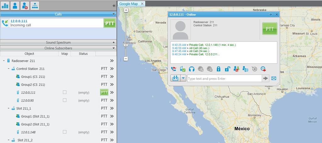
229 User 2: 229
. For more details see the Multigroups section in the Help of SmartPTT Radioserver Configurator. The following example demonstrates a call to Group 1.")
230 To redirect only group calls between two radioservers without setting up routes in SmartPTT Dispatcher, create multigroups with the list of radios, that support group call bridging in SmartPTT Radioserver Configurator (for both radioservers). For more details see the Multigroups section in the Help of SmartPTT Radioserver Configurator. The following example demonstrates a call to Group 1. Group 1 corresponds to the created Multigroup 1 with the a list of radios 95 (IP address = ) and 404 (IP address = ). The radio with the IP address = (ID = 404) initiates a group call. The radio with the IP address = (ID = 95) is also able to participate in the call due to Multigroup

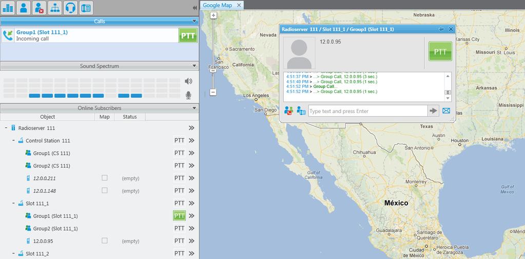
231 User 2: User 1: 231

232 Client List The Client List tab enables you to see the lists of client applications connected to the radioserver and to manage the settings of the users created to work with the web application. To open the list of client applications connected to the radioserver, click the Client List tab and click Active. Client Name: Name of the desktop version of the dispatch console, the operator's name, or web application connected to the radioserver. If Windows Authentication is enabled in SmartPTT Dispatcher > Settings > General Settings, you can also see the name of the Windows group (which, in this case, corresponds to the name of the operator) and the name of the Windows user logged into Windows. Address: The IP address of the client application. Connect Time: Time of the last session. Profile: Assigned profile to the dispatcher or to the user of the web application. Note: To assign a profile to the dispatcher, click Settings > Radioservers in SmartPTT Dispatcher. For more information about profiles see Profiles in the Help document. To connect the desktop version of the dispatch console to the radioserver, go to Settings > Radioservers in SmartPTT Dispatcher and select the radioserver to which you want to be connected. At that, in the Client List tab of SmartPTT Radioserver Configurator the connected dispatch console will show up. How to connect the user of the web application to the radioserver, please check WebClient Installation & Configuration for SmartPTT. 232

233 To open the list of users created to work with the mobile and web clients, click All (mobile and web clients). The Login list: The list of users of the SmartPTT web application. To add new user, click the Add button. In the Parameters section specify the user name in the Login field and set the password by clicking the Change password button. The user name and password are case sensitive. Profile: It contains the list of profiles created in SmartPTT Radioserver Configurator (see the Settings tab > Profiles). Assigning a profile to the user is not obligatory, but enables you to limit the user's access to objects and to provide additional opportunities in the organization of calls between user and radio subscribers. For more information about profiles see Profiles in the Help document. Allow voice calls: Select it to enable the user to make voice calls. To edit the parameters of the existing user, click this user in the Login list, and edit the necessary fields in the Parameters section. To delete user, click this user in the Login list, and click the Delete button. To save the changes, click the Save button in the bottom right corner of the SmartPTT Radioserver Configurator. 233

234 Rules SmartPTT Radioserver allows you to set up rules to perform automatic actions (playback sounds, send messages, play predefined voice notifications) based on conditions specified in the Rules tab in SmartPTT Radioserver Configurator. To set up rules, open the Rules tab in SmartPTT Radioserver Configurator. Events on radios: Allows you to create rules related to subscriber radios. Events on Dispatcher: Allows you to create rules related to SmartPTT Dispatcher. 234

235 To create a new rule for events on radios, click Events on radios and then click Add. To change the existing rule, click Modify or double-click on the rule name in the list of rules. Name: Any name of the rule. Active: If selected, the rule will be used in the system. Under Conditions you can select criteria of the rule. Condition name Direction Operation Equal to Value Incoming, Outgoing 235
236 Condition name Event Type Operation Equal to, Not equal to Value ARS, Call, Message, Telemetry, Alarm, Block Date Between Period of time Additional Information Equal to, Contains Any additional information, e. g. text messages, titles and description of tasks, participants of a group call. Control Station Equal to, Contains Control station name Talkgroup Equal to, Contains Talkgroup name Subscriber Equal to, Not equal to Subscriber ID Status Equal to, Not equal to One of system statuses of events Duration Equal to, Not equal to, Greater than, Greater Duration of time (seconds) than or equal to, Less than, Less than or equal to, Between 236

237 To create a new rule for events on SmartPTT Dispatcher, click Events on Dispatcher and then click Add. To change the existing rule, click Modify or double-click on the rule name in the list of rules. Connection to Radioserver: If Lost is selected, the system performs predefined actions when the connection between SmartPTT radioserver and the last dispatch console is terminated. If Restored is selected, the system performs predefined actions when the first dispatch console connects SmartPTT radioserver. Timeout (s): Time period in seconds, after which the SmartPTT radioserver performs actions defined under the Actions area. Under Actions you can define actions, which the system will perform when the rule conditions are fulfilled: Play Sound: When selected, you can specify the path to the folder with the audio file to play, and select a subscriber or a talkgroup to whom you want it to be sent. Supported audio file formats are MP3, OGG, WAV. Send Message: When selected, you can type a text message, select recipients (subscribers or a talkgroup), and the Send Message to Initiator option. Start Voice Notification: When selected, you can specify the notification to play (to learn how to create a voice notification, see Voice Notifications). If the rule conditions were fulfilled at the moment when the operator 237

238 played a voice notification, the voice notification specified in the rule actions won't play. To avoid this, select Stop Current Voice Notification. You can also specify which notification must be stopped. Activity The Activity tab displays events that happen in the radio network. Mostly, it is used for debugging purposes, but it can be useful for system administrators as well. To open Activity, click the Activity tab in SmartPTT Radioserver Configurator. There are six types of events logged: Registration, Messages, Locations, Telemetry, Calls, Other (includes connection or disconnection of slots or control stations), You can enter the radio ID into the Radio ID field to view the events related to the particular subscriber. You should select one or several of those chekboxes to view events in the list. All events are listed in the table with the following columns: Date/Time: The date and time of the event, Type: The one of the listed types above, System: The network where event happened, Event: The brief description of the event and its status. You can apply the following settings for the list of events: Auto Scroll: Select to make auto refresh of the list of events. When a new event will happen in the system, it will occur in the top of the list. 238

239 Clear Activity Log: Click to remove all events from the table. Events will be kept in the log files, they would be unavailable in the table of the Activity tab. Example: sending GPS Network Configuration In the Network Configuration tab you can set up elements of the networks used in the system. The added elements will be displayed in the Topology tab of SmartPTT Dispatcher. You can also set up sending of alarm notifications to predefined addresses. Note: This tab is available only if there is a license for monitoring. If you have it, make sure you have selected the Active check box in the Monitoring window. To add elements of the network, select the network in the list. The supported network elements include: repeaters, routers, UPS and location. To add devices, open the context menu by right-clicking on the existing network. Radioservers are added automatically with the name Server. To delete the created object, right-click on the object and then click Remove Repeater, Remove Device or Remove Location respectively. 239

240 Adding Repeater To add a repeater, click Add Repeater in the context menu. At that, the window for setting up repeater parameters will open. Peer ID: Unique identifier of the repeater. Name: Any random name of the repeater. The name will be used in the Topology tab in SmartPTT Dispatcher. If the name is not set, the name from the repeater codeplug will be displayed. Description: Random description of the repeater. SNMP Parameters: Here you can set up the community name, which is used as a password for the external SNMP client to connect to the repeater. o Active: Enable/Disable the external SNMP client. o Community: Community name used as a password for the external SNMP client to connect to the repeater. In the Alarm Notifications tab you can set up automatic notification of alarms or errors occurred in the repeater. You can have the notifications sent to your address, to your cell phone, to an SNMP client or to radio subscribers. 240
 Eaton9130 (UPS) Huawei Router UPS ATS-Convers Supermicro Server.")
241 Adding UPS and Routers and other devices The supported devices include a router and an uninterruptible power supply (UPS). To add a device, click Add Device in the context menu. At that, the following window will open. Type: Device type. There are the following devices to choose from: Cisco2900 (router) Eaton9130 (UPS) Huawei Router UPS ATS-Convers Supermicro Server. This server allows you to receive information about the state of the radioserver and errors occurred on the radioserver. To be able to receive alarms from the radioserver, add Supermicro Server. If there are any alarms on the radioserver, you will see them in Monitoring event log in SmartPTT Dispatcher. Apc 5000 Unknown (for other devices not specified in the list) Name: Random name of the device which is displayed in Topology in SmartPTT Dispatcher. 241
242 Description: Random description of the device. Interface: The radioserver IP address used for interacting with the device. IP-address: IP address of the device. SNMP Version: Version of SNMP protocol used in the system. There are two options: versions 1 and 2 (V1 and V2). Community: Community name, which is used as password to locally connect to the device over SNMP protocol. Response Timeout, s: Time during which the server expects a response from the device. The maximum value is 10 sec. Polling Interval, s: Time period at the end of which the radioserver sends a request to the device. The default value is 30 sec. Check Connection: Checks if there is a connection to the device. At clicking the button a new window with the information on the connection status opens. SNMP Parameters: o Active: Enable/Disable the external SNMP client. o External Community: Special community name which is used as password to connect to the device via external SNMP client. To set up the automatic alarm notifications from the device, go to the Alarm Notifications tab. 242

243 Adding Location If there are many repeaters and devices, they can be grouped by location. In LCP systems a location represents a site (you can define Site ID). In Connect Plus systems a location can be used for added XRC controller. To add a location, select the Add Location option in the context menu. At that, the following window will open. Name: Any random name of the location. The name is displayed in the Topology tab in SmartPTT Dispatcher. Description random description of the location which is displayed in the Topology tab in SmartPTT Dispatcher when hovering the mouse pointer over the object. Initial State defines how the location object is to be displayed in the Topology tab in SmartPTT Dispatcher. If the check box is selected, all the devices and repeaters allocated to the location will be displayed by default. If the check box is not selected, the devices won t be seen inside the location by default. In this case, to see the devices, you will need to click on the location object in the Topology tab. To add or remove a device or repeater from the location, simply drag it to another place. Note: When deleting a location with devices and repeaters allocated to it, all the devices will be deleted together with the location. 243

244 You can upload the network elements, instead of adding them manually. To do it, click Update Topology. At that, a pop-up window will open and the update process will start: Stop: Interrupts the ongoing update process. All the changes that were made prior interruption these you can see in the Changes table will be applied after clicking OK. Remove missing peers: Checks if there are any missing peers to exclude them from network topology. Update names: Replaces names of repeaters by those defined in CPS. The Changes table shows all the changes made during the update process. You can discard changes by clicking Cancel. To discard all changes, click Cancel All. To apply the changes, click OK. Alarm Notifications SmartPTT can notify radio and telephone subscribers, and other users about errors or other malfunctions occurred on devices used in the system or occurred during the redudnancy. 244

245 To set up automatic radioserver redundancy error notifications, in the left list of the Network Configuration tab click Radioserver (here your radioserver name is displayed) and create the list of notifications receivers. To do it, click Add. There are several types of receivers: individual radio subscribers, talkgroups, telephone subscribers, users, SNMP clients. 245

246 To set up automatic alarm notifications, click Alarm Notifications in the Network Monitoring window: Select all the alarms you want to be notified about. Then create the list of notifications receivers. To do it, click Add. There are several types of receivers: individual radio subscribers, talkgroups, telephone subscribers, users, SNMP clients. The alarm notifications set in the Network Monitoring tab are applied to all elements of the radio network, but you can change them for each element of the network. 246

247 Log The Log tab was designed to give information about the radio service system events. Mostly it is used for debugging purposes. To see the log of the radio service, open the Log tab. 247
 with similar configuration settings becomes much easier and quicker.")
248 Export/Import Settings SmartPTT Radioserver allows exporting configuration settings and database from one radioserver and importing them into another. Thus, the process of setting up new radioserver(s) with similar configuration settings becomes much easier and quicker. How to Export or Import Settings To export or import the radioserver settings or/and the database, click Export/Import Settings. Note: Before exporting or importing the radioserver configuration settings and the database, stop the server. Otherwise, the buttons Browse, Export and Import will be unavailable. Exporting the Settings and/or the Database To export the settings and/or the database of the radioserver, take the following steps: 1. Stop the radioserver. 2. Select the file where you want the settings to be exported by entering the path to the file in the Save Export File As field or by clicking Browse. 248
249 3. Select Export Radioserver Database if you want the database to be exported too. 4. Click Export. Note: You cannot export the radioserver database separately, i.e., without the settings. Importing the Settings and/or the Database To import the settings and/or the database to the radioserver, take the following steps: 1. Stop the radioserver. 2. Select the file from where you want the settings to be imported by entering the path to the file in the Choose File to Import field or by clicking Browse. 3. Select Import Radioserver Database if you want the database to be imported too. 4. Select the import mode: 1) Keep Server GUID: Import mode when the server globally unique ID is left unchanged. After importing, there are two servers with same configuration settings, but different globally unique GUID s. 2) All: Import mode when all the server configuration settings, including the GUID, are replaced with the imported values. After importing, there are two servers with absolutely identical settings and GUID s. 5. Click Import. Note: After importing the radioserver settings with the option to override all the existing settings (All), it is important to delete one of the two servers to avoid GUID conflict. 249
. The space on the hard drive used by the audio records (the Audio field).")

250 Statistics The Statistics tab demonstrates you the following information: The total number of events on the radioserver (the Events field). The space on the hard drive used by the databases (the Database field). The space on the hard drive used by the audio records (the Audio field). When the total size of records in your database exceeds 90% of the maximal size, a message will appear: From this message you can learn the size of the records in your database. This message will appear at the every start of SmartPTT Radioserver Configurator. Then, if database is not cleaned up, it will appear every 30 min. 250
SmartPTT. Indoor Positioning Service
 SmartPTT Indoor Positioning Service October 2018 Indoor Tracking in SmartPTT Configurator Indoor Tracking in SmartPTT Configurator Big organizations with huge premises require constant control over their
Version 8.8 Linked Capacity Plus. Configuration Guide
 Version 8.8 Linked Capacity Plus February 2016 Table of Contents Table of Contents Linked Capacity Plus MOTOTRBO Repeater Programming 2 4 MOTOTRBO Radio Programming 14 MNIS and DDMS Client Configuration
Version 9.1. Installation & Configuration Guide
 Version 9.1 SmartPTT PLUS November 2016 Table of Contents Table of Contents Introduction 2 Installation of the SmartPTT software 2 General SmartPTT Radioserver Configuration 6 SmartPTT Dispatcher Configuration
Version 9.1 SmartPTT Enterprise. Installation & Configuration Guide
 Version 9.1 SmartPTT Enterprise December 2016 Table of Contents Table of Contents 1.1 Introduction 3 1.2 Installation of the SmartPTT software 3 1.3 General SmartPTT Radioserver Configuration 7 1.4 SmartPTT
Version 9.1 SmartPTT Monitoring
 Version 9.1 SmartPTT Monitoring December 2016 Table of Contents Table of Contents 1.1 Introduction 2 1.2 Installation of the SmartPTT software 2 1.3 General SmartPTT Radioserver Configuration 6 1.4 SmartPTT
Version SmartPTT Enterprise. Installation and Configuration Guide
 Version 9.3.1 July 2018 Contents Contents 1 Introduction 4 2 Preliminary Actions 5 2.1 HDD Space Estimation 5 3 Installation of SmartPTT Software 7 4 General SmartPTT Radioserver Configuration 12 5 SmartPTT
Version 9.2. SmartPTT PLUS. Capacity Max Configuration Guide
 Version 9.2 Configuration Guide Januar 2018 Contents Contents 1 3 1.1 Configuring 5 1.2 Configuring Trunk Controller 9 1.3 Configuring MNIS Data Gateway 15 1.4 Configuring MNIS VRC Gateway 22 1.5 Configuring
Configuration Guide. Version 8.3
 Capacity Plus Configuration Guide Version 8.3 Table of Contents 1 Table of Contents 1 Introduction 2 2 Brief Information on Use of Control Stations 4 3 6 3.1 Programming Repeter 7 3.1.1 Master Repeater
"Terminal RG-1000" Customer Programming Software. User Guide. August 2016 R4.3
 "Terminal RG-1000" Customer Programming Software User Guide August 2016 R4.3 Table of Contents Table of Contents Introduction 2 3 1.1 Software installation 3 1.2 Connecting the RG-1000 GATEWAYs to the
Networks of any size and topology. System infrastructure monitoring and control. Bridging for different radio networks
 INTEGRATED SOLUTION FOR MOTOTRBO TM Networks of any size and topology System infrastructure monitoring and control Bridging for different radio networks Integrated Solution for MOTOTRBO TM Networks of
TRBOnet Mobile. User Guide. for ios. Version 1.8. Internet. US Office Neocom Software Jog Road, Suite 202 Delray Beach, FL 33446, USA
 TRBOnet Mobile for ios User Guide Version 1.8 World HQ Neocom Software 8th Line 29, Vasilyevsky Island St. Petersburg, 199004, Russia US Office Neocom Software 15200 Jog Road, Suite 202 Delray Beach, FL
Version 9.3. SmartPTT Enterprise. Release Notes
 Version 9.3 June 2018 New Features 2 New Features Backhaul Repeater Chains supports the Backhaul Repeater Chains (BRC) feature in digital conventional radio systems. Both legacy IP Site Connect and IP
SafeMobile Radio Configuration
 SafeMobile Radio Configuration SafeMobile offers a world of wireless applications that help organizations better manage their mobile assets, fleet and personnel. For more information, see www.safemobile.com.
US VERSION GW3-TRBO RESELLER PRICES FOR MOTOTRBO GW3-TRBO
 US VERSION RESELLER PRICES GW3-TRBO FOR MOTOTRBO GW3-TRBO Network Management Software for MOTOTRBO GW3-TRBO is the system management tool for MOTOTRBO systems developed by The Genesis Group. GW3-TRBO is
TRBOnet Enterprise. IP Site Connect. Deployment Guide. Internet. US Office Neocom Software Jog Road, Suite 202 Delray Beach, FL 33446, USA
 TRBOnet Enterprise IP Site Connect Deployment Guide World HQ Neocom Software 8th Line 29, Vasilyevsky Island St. Petersburg, 199004, Russia US Office Neocom Software 15200 Jog Road, Suite 202 Delray Beach,
Customer Programming Software RG-1000e (CPS RG-1000e) User Guide. October 2017 R2.0
 User Guide. October 2017 R2.0") Customer Programming Software RG-1000e (CPS RG-1000e) User Guide October 2017 R2.0 Table of Contents Table of Contents Foreword 2 Revision history 3 Introduction 4 5 1.1 Software installation 5 1.2 Connecting
Customer Programming Software RG-1000e (CPS RG-1000e) User Guide October 2017 R2.0 Table of Contents Table of Contents Foreword 2 Revision history 3 Introduction 4 5 1.1 Software installation 5 1.2 Connecting
TRBOnet Mobile. User Guide. for Android. Version 2.0. Internet. US Office Neocom Software Jog Road, Suite 202 Delray Beach, FL 33446, USA
 TRBOnet Mobile for Android User Guide Version 2.0 World HQ Neocom Software 8th Line 29, Vasilyevsky Island St. Petersburg, 199004, Russia US Office Neocom Software 15200 Jog Road, Suite 202 Delray Beach,
TRBOnet Enterprise. Extended Range Direct Mode. Deployment Guide. Internet
 TRBOnet Enterprise Extended Range Direct Mode Deployment Guide World HQ Neocom Software 8th Line 29, Vasilyevsky Island St. Petersburg, 199004, Russia US Office Neocom Software 15200 Jog Road, Suite 202
TRBOnet Enterprise. Capacity Plus. Deployment Guide. Internet. US Office Neocom Software Jog Road, Suite 202 Delray Beach, FL 33446, USA
 TRBOnet Enterprise Capacity Plus Deployment Guide World HQ Neocom Software 8th Line 29, Vasilyevsky Island St. Petersburg, 199004, Russia US Office Neocom Software 15200 Jog Road, Suite 202 Delray Beach,
Version SmartPTT Enterprise. Web Client User Guide
 Version 9.3.1 July 2018 Contents Contents 1 Introduction 3 2 SmartPTT Web Client Interface 4 3 Logging in and Changing User 6 4 7 4.1 Making and Receiving Voice Calls 8 4.2 Sending Messages 11 4.3 Finding
Kodiak Corporate Administration Tool
 AT&T Business Mobility Kodiak Corporate Administration Tool User Guide Release 8.3 Table of Contents Introduction and Key Features 2 Getting Started 2 Navigate the Corporate Administration Tool 2 Manage
TRBOnet Enterprise. Linked Capacity Plus. Deployment Guide. Internet. US Office Neocom Software Jog Road, Suite 202 Delray Beach, FL 33446, USA
 TRBOnet Enterprise Linked Capacity Plus Deployment Guide World HQ Neocom Software 8th Line 29, Vasilyevsky Island St. Petersburg, 199004, Russia US Office Neocom Software 15200 Jog Road, Suite 202 Delray
Customer Programming Software RG-1000e (CPS RG-1000e) User Guide. March 2018 R2.2.1
 User Guide. March 2018 R2.2.1") Customer Programming Software RG-1000e (CPS RG-1000e) User Guide March 2018 R2.2.1 Table of Contents Table of Contents Foreword 3 Revision history 4 Introduction 5 1. RG-1000e Customer Programming Software
Customer Programming Software RG-1000e (CPS RG-1000e) User Guide March 2018 R2.2.1 Table of Contents Table of Contents Foreword 3 Revision history 4 Introduction 5 1. RG-1000e Customer Programming Software
Hytera. PD41X Patrol Management System. Installation and Configuration Guide
 Hytera PD41X Patrol Management System Installation and Configuration Guide Documentation Version: 01 Release Date: 03-2015 Copyright Information Hytera is the trademark or registered trademark of Hytera
TRBOnet Enterprise/PLUS
 TRBOnet Enterprise/PLUS Bluetooth-based Indoor Positioning User Guide Version 5.2 World HQ Neocom Software 8th Line 29, Vasilyevsky Island St. Petersburg, 199004, Russia US Office Neocom Software 15200
DRG-Series. Digital Radio Gateway. Motorola MotoTRBO DMR. Interfacing Omnitronics DRG with Motorola MotoTRBO DMR Digital Radios
 DRG-Series Digital Radio Gateway Motorola MotoTRBO DMR Interfacing Omnitronics DRG with Motorola MotoTRBO DMR Digital Radios Digital Radio Supplement DRG-Series Supplement Interfacing Omnitronics DRG with
Customer Programming Software RG-1000e (CPS RG-1000e) User Guide. June 2018 R2.2.2 v2
 User Guide. June 2018 R2.2.2 v2") Customer Programming Software RG-1000e (CPS RG-1000e) User Guide June 2018 R2.2.2 v2 Table of Contents Table of Contents Foreword 3 Revision history 4 Introduction 5 1. RG-1000e Customer Programming Software
Customer Programming Software RG-1000e (CPS RG-1000e) User Guide June 2018 R2.2.2 v2 Table of Contents Table of Contents Foreword 3 Revision history 4 Introduction 5 1. RG-1000e Customer Programming Software
TRBOnet 5.1 New Features
 TRBOnet 5.1 New Features January 24, 2017 www.trbonet.com Radio Kill for CapMax 2.7 Allows the dispatcher to kill a radio. The killed radio is not operable, and can be recovered by Motorola only. Users
DRG-Series. Digital Radio Gateway. Hytera DMR USB Donor (Tier-2) Digital Radio Supplement
 Digital Radio Supplement") DRG-Series Digital Radio Gateway Hytera DMR USB Donor (Tier-2) Digital Radio Supplement DRG-Series Digital Radio Gateway Hytera DMR USB Donor (Tier-2) Digital Radio Supplement 2015 Omnitronics Pty Ltd.
DRG-Series Digital Radio Gateway Hytera DMR USB Donor (Tier-2) Digital Radio Supplement DRG-Series Digital Radio Gateway Hytera DMR USB Donor (Tier-2) Digital Radio Supplement 2015 Omnitronics Pty Ltd.
CTI Products RadioPro Dispatch Demo Installation and Test Drive Document # S For Version 8 Software
 CTI Products RadioPro Dispatch Demo Installation and Test Drive Document # S2-61570-801 For Version 8 Software Contact Us Support, replacement part ordering, and service may be arranged by contacting our
TRBOnet Enterprise 2.6 for MOTOTRBO Capacity Plus.
 TRBOnet Enterprise 2.6 for MOTOTRBO Capacity Plus Neocom Software Ltd: TRBOnet Team Software Products 7 products Custom Development Feature requests Software integration Support Team More than 200+ systems
CTI Products RadioPro Dispatch User Guide Document # S For Version 8 Software
 CTI Products RadioPro Dispatch Document # S2-61786-809 For Version 8 Software Contact Us Support, replacement part ordering, and service may be arranged by contacting our Cincinnati office. Parts for service
DRG-Series. Digital Radio Gateway. Tait P25 CCDI Tier-2 (TM9400 Series Mobile Radio) Digital Radio Supplement
 Digital Radio Supplement") DRG-Series Digital Radio Gateway Tait P25 CCDI Tier-2 (TM9400 Series Mobile Radio) Digital Radio Supplement DRG-Series Digital Radio Gateway Tait P25 CCDI Tier-2 (TM9400 Series Mobile Radio) Digital Radio
DRG-Series Digital Radio Gateway Tait P25 CCDI Tier-2 (TM9400 Series Mobile Radio) Digital Radio Supplement DRG-Series Digital Radio Gateway Tait P25 CCDI Tier-2 (TM9400 Series Mobile Radio) Digital Radio
DRG-Series. Digital Radio Gateway. Kenwood NXDN Donor Radio (Tier-2) Interfacing Omnitronics DRG with Kenwood NXDN Donor Digital Radios (Tier-2)
 Interfacing Omnitronics DRG with Kenwood NXDN Donor Digital Radios (Tier-2)") DRG-Series Digital Radio Gateway Kenwood NXDN Donor Radio (Tier-2) Interfacing Omnitronics DRG with Kenwood NXDN Donor Digital Radios (Tier-2) Digital Radio Supplement DRG-Series Supplement Kenwood NXDN
DRG-Series Digital Radio Gateway Kenwood NXDN Donor Radio (Tier-2) Interfacing Omnitronics DRG with Kenwood NXDN Donor Digital Radios (Tier-2) Digital Radio Supplement DRG-Series Supplement Kenwood NXDN
TurboVUi Solo. User Guide. For Version 6 Software Document # S Please check the accompanying CD for a newer version of this document
 TurboVUi Solo For Version 6 Software Document # S2-61432-604 Please check the accompanying CD for a newer version of this document Remote Virtual User Interface For MOTOTRBO Professional Digital 2-Way
Hytera Smart Dispatch
 Hytera Smart Dispatch Integrated software to monitor, control, and communicate with your radio fleet Flexible System Deployment with an Easy User Interface Hytera Quick GPS Maximizes use of Channel Resources
Hytera DMR Conventional Series
 Hytera DMR Conventional Series SIP Phone Gateway to Simultaneous Calls Application Notes Document version: 3.0 Date: 02-2015 Copyright Information Hytera is the trademark or registered trademark of Hytera
Understanding PMC Interactions and Supported Features
 CHAPTER3 Understanding PMC Interactions and This chapter provides information about the scenarios where you might use the PMC, information about the server and PMC interactions, PMC supported features,
TRBOnet Guard Tour Configuration and Operation Guide
 TRBOnet Guard Tour and Operation Guide Version 5.0 World HQ Neocom Software 8th Line 29, Vasilyevsky Island St. Petersburg, 199004, Russia US Office Neocom Software 15200 Jog Road, Suite 202 Delray Beach,
TRBOnet Enterprise/PLUS
 TRBOnet Enterprise/PLUS Guard Tour User Guide Version 5.2 World HQ Neocom Software 8th Line 29, Vasilyevsky Island St. Petersburg, 199004, Russia US Office Neocom Software 15200 Jog Road, Suite 202 Delray
GW3-TRBO Trbo Module Software Version 2.14 Module Book
 GW3-TRBO Trbo Module Software Version 2.14 Module Book 2/20/2017 2006-2017 The Genesis Group 2 Trademarks The following are trademarks of Motorola: MOTOTRBO. Any other brand or product names are trademarks
LincView OPC USER GUIDE. Enhanced Diagnostics Utility INDUSTRIAL DATA COMMUNICATIONS
 USER GUIDE INDUSTRIAL DATA COMMUNICATIONS LincView OPC Enhanced Diagnostics Utility It is essential that all instructions contained in the User Guide are followed precisely to ensure proper operation of
MOTOTRBO CAPACITY MAX
 MOTOTRBO CAPACITY MAX MOTOTRBO CAPACITY MAX Next generation trunking solution Increased capacity and scalability Enhanced performance and feature-set Improved management and monitoring DMR Tier III Mode
PROFESSIONAL DIGITAL TWO-WAY RADIO SYSTEM. MOTOTRBO XiR M8220/ XiR M8228 NUMERIC DISPLAY MOBILE USER GUIDE
 PROFESSIONAL DIGITAL TWO-WAY RADIO SYSTEM MOTOTRBO XiR M8220/ XiR M8228 NUMERIC DISPLAY MOBILE USER GUIDE Contents This User Guide contains all the information you need to use the MOTOTRBO XiR Series
DRG-Series. Digital Radio Gateway. Icom IDAS Conventional Wireline IP (Tier-2) (IC-FR5000/IC-FR6000 IDAS VHF/UHF Repeaters) Digital Radio Supplement
 (IC-FR5000/IC-FR6000 IDAS VHF/UHF Repeaters) Digital Radio Supplement") DRG-Series Digital Radio Gateway Icom IDAS Conventional Wireline IP (Tier-2) (IC-FR5000/IC-FR6000 IDAS VHF/UHF Repeaters) Digital Radio Supplement DRG-Series Digital Radio Gateway Icom IDAS Conventional
DRG-Series Digital Radio Gateway Icom IDAS Conventional Wireline IP (Tier-2) (IC-FR5000/IC-FR6000 IDAS VHF/UHF Repeaters) Digital Radio Supplement DRG-Series Digital Radio Gateway Icom IDAS Conventional
DRG-Series. Digital Radio Gateway. Icom IDAS MultiTrunk IP (Tier-3) Digital Radio Supplement
 Digital Radio Supplement") DRG-Series Digital Radio Gateway Icom IDAS MultiTrunk IP (Tier-3) Digital Radio Supplement DRG-Series Digital Radio Gateway Icom IDAS MultiTrunk IP (Tier-3) Digital Radio Supplement 2015 2017 Omnitronics
DRG-Series Digital Radio Gateway Icom IDAS MultiTrunk IP (Tier-3) Digital Radio Supplement DRG-Series Digital Radio Gateway Icom IDAS MultiTrunk IP (Tier-3) Digital Radio Supplement 2015 2017 Omnitronics
User Guide. PTT Radio Application. Android. Release 8.3
 User Guide PTT Radio Application Android Release 8.3 March 2018 1 Table of Contents 1. Introduction and Key Features... 5 2. Application Installation & Getting Started... 6 Prerequisites... 6 Download...
CTI Products. RadioPro IP Gateway. Installation Guide. Document # S For Version 8 Software
 CTI Products RadioPro IP Gateway Installation Guide Document # S2-61781-809 For Version 8 Software A newer version of this document may be available. Please check the accompanying CD or www.ctiproducts.com
DP 3600 / DP 3601 Display Portable
 Professional Digital Two-Way Radio System DP 3600 / DP 3601 Display Portable User Guide Contents This User Guide contains all the information you need to use the MOTOTRBO Series Portables. Important Safety
FAQ and Solutions. 02 May TM and copyright Imagicle spa
 FAQ and Solutions 02 May 2018 TM and copyright 2010-2018 Imagicle spa Table of Contents FAQ and Solutions...1/11 SkyStone and network security settings...1/11 Upgrade procedure to support Skype 7.32...2/11
Enhanced Push-to-Talk Application for iphone
 AT&T Business Mobility Enhanced Push-to-Talk Application for iphone Standard Version Release 8.3 Table of Contents Introduction and Key Features 2 Application Installation & Getting Started 2 Navigating
MOTOBRIDGE Dispatch Application Overview
 MOTOBRIDGE Dispatch Application Overview MOTOBRIDGE IP Interoperable Solution Dispatcher Training July 2009 Starting the Local Dispatch Application Enter the user name and password. Click the OK button.
2.11 Over The Air Battery Management
 118 System Feature Overview 2.11 Over The Air Battery Management When a battery fails and communication is lost, it impacts every aspect of an organization from serving customers to saving lives. But monitoring
INDEX...2 INTRODUCTION...3 IMPORTANT NOTES...3 INSTALLING THE SOFTWARE...3 ST-965 PROGRAMMING SOFTWARE...6
 ST-965 VX/D SMARTRUNK II & SMARTRUNK XPRESS Logic board Programming Software 2.9e User s Guide Revision R2.9 10/10/2008 INDEX INDEX...2 INTRODUCTION...3 IMPORTANT NOTES...3 INSTALLING THE SOFTWARE...3
PROFESSIONAL DIGITAL TWO-WAY RADIO MOTOTRBO DM4400/DM4401/DM4400e/DM4401e NUMERIC DISPLAY MOBILE USER GUIDE. es-es
 PROFESSIONAL DIGITAL TWO-WAY RADIO MOTOTRBO DM4400/DM4401/DM4400e/DM4401e NUMERIC DISPLAY MOBILE USER GUIDE en de-de fr-fr pl ru ar-eg it-it es-es tr Contents Important Safety Information...8 Software
DragonLink Advanced Transmitter
 DragonLink Advanced Transmitter A quick introduction - to a new a world of possibilities October 29, 2015 Written by Dennis Frie Contents 1 Disclaimer and notes for early release 3 2 Introduction 4 3 The
Hytera DMR Conventional Series Release Notes
 Hytera DMR Conventional Series Release Notes DMR Conventional Software Version: 6.00 Release Notes Version: 6.00.02 Software Release Date: 31-03-2014 Date: 31-03-2014 Copyright Information Hytera is the
Enhanced Push-to-Talk Application for iphone
 AT&T Business Mobility Enhanced Push-to-Talk Application for iphone Land Mobile Radio (LMR) Version Release 8.3 Table of Contents Introduction and Key Features 2 Application Installation & Getting Started
Managing Radios and Radio Descriptors
 CHAPTER9 The Cisco IPICS administrator is responsible for configuring the radios and radio descriptors that are used with Cisco IPICS. This chapter provides detailed information about managing these items.
INDEX...2 INTRODUCTION...3 IMPORTANT NOTES...3 INSTALLING THE SOFTWARE...3 ST-965 PROGRAMMING SOFTWARE...6
 ST-965 KW/D SMARTRUNK II & SMARTRUNK XPRESS Logic board Programming Software 2.9e User s Guide Revision R2.9.8 12/30/2008 INDEX INDEX...2 INTRODUCTION...3 IMPORTANT NOTES...3 INSTALLING THE SOFTWARE...3
User Guide. PTT Radio Application. ios. Release 8.3
 User Guide PTT Radio Application ios Release 8.3 March 2018 1 Table of Contents 1. Introduction and Key Features... 5 2. Application Installation & Getting Started... 6 Prerequisites... 6 Download... 6
Genesis Channel Manager
 Genesis Channel Manager VPI 160 Camino Ruiz, Camarillo, CA 93012-6700 (Voice) 800-200-5430 805-389-5200 (Fax) 805-389-5202 www.vpi-corp.com 1 Contents Genesis Channel Manager -----------------------------------------------------------------------------------------------------------------
Field Device Manager Express
 Honeywell Process Solutions Field Device Manager Express Software Installation User's Guide EP-FDM-02430X R430 June 2012 Release 430 Honeywell Notices and Trademarks Copyright 2010 by Honeywell International
Frequently Asked Questions ConnexRF Products
 ConnexRF Products Version 1.1 PKLR2400S-200A PKLR2400S-10 LX2400S-3A LX2400S-10 13256 W. 98 TH STREET LENEXA, KS 66215 (800) 492-2320 www.aerocomm.com wireless@aerocomm.com DOCUMENT INFORMATION Copyright
INSTRUCTION MANUAL IP REMOTE CONTROL SOFTWARE RS-BA1
 INSTRUCTION MANUAL IP REMOTE CONTROL SOFTWARE RS-BA FOREWORD Thank you for purchasing the RS-BA. The RS-BA is designed to remotely control an Icom radio through a network. This instruction manual contains
1. Product Introduction FeasyBeacons are designed by Shenzhen Feasycom Technology Co., Ltd which has the typical models as below showing: Model FSC-BP
 ,,,,,,,,,,,,,,,,,,,,,,,,,,,,,,,,,,,,,,,,,,,,,,,,,,,, FeasyBeacon Getting Started Guide Version 2.5 Feasycom Online Technical Support: Skype: Feasycom Technical Support Direct Tel: 086 755 23062695 Email:
AT-D868UV CodePlug Programming Guide
 INTRODUCTION The AnyTone D868UV radio is a VHF and UHF radio with both Digital DMR (Tier I and II) and Analog capabilities. It offers a total of 4,000 channels (Analog and Digital) and up to 130,000 contacts,
PROFESSIONAL DIGITAL TWO-WAY RADIO SYSTEM MOTOTRBO DP 3600/DP 3601 DISPLAY PORTABLE QUICK REFERENCE GUIDE
 PROFESSIONAL DIGITAL TWO-WAY RADIO SYSTEM MOTOTRBO DP 3600/DP 3601 DISPLAY PTABLE QUICK REFERENCE GUIDE m DP 3600/3601 Portables Quick Reference Guide Important Safety Information Product Safety and RF
User Guide: PTT Radio Application - ios. User Guide. PTT Radio Application. ios. Release 8.3
 User Guide PTT Radio Application ios Release 8.3 December 2017 Table of Contents Contents 1. Introduction and Key Features... 5 2. Application Installation & Getting Started... 6 Prerequisites... 6 Download...
MOTOTRBO R1.8 Training Overview
 MOTOTRBO R1.8 Training Overview MOTOTRBO System Training Release1.8 MOTOROLA, MOTO, MOTOROLA SOLUTIONS and the Stylized M Logo are trademarks or registered trademarks of Motorola Trademark Holdings, LLC
User Guide: PTT Application - Android. User Guide. PTT Application. Android. Release 8.3
 User Guide PTT Application Android Release 8.3 March 2018 1 1. Introduction and Key Features... 6 2. Application Installation & Getting Started... 7 Prerequisites... 7 Download... 8 First-time Activation...
UCP-Config Program Version: 3.28 HG A
 Program Description HG 76342-A UCP-Config Program Version: 3.28 HG 76342-A English, Revision 01 Dev. by: C.M. Date: 28.01.2014 Author(s): RAD Götting KG, Celler Str. 5, D-31275 Lehrte - Röddensen (Germany),
EDACS SYSTEM MANAGER. User s Guide. Mobile Communications. User s Guide For Version 3.XX (Group 3) LBI-38984
 LBI-38984") Mobile Communications EDACS SYSTEM MANAGER (Enhanced Digital Access Communications System) User s Guide For Version 3.XX (Group 3) User s Guide TABLE OF CONTENTS Page Section/Paragraph INTRODUCTION..................................................
Mobile Communications EDACS SYSTEM MANAGER (Enhanced Digital Access Communications System) User s Guide For Version 3.XX (Group 3) User s Guide TABLE OF CONTENTS Page Section/Paragraph INTRODUCTION..................................................
GW3-TRBO Affiliation Software Version 2.15 Module Book
 GW3-TRBO Affiliation Software Version 2.15 Module Book 1/17/2018 2011-2018 The Genesis Group 2 Trademarks The following are trademarks of Motorola: MOTOTRBO. Any other brand or product names are trademarks
Manager Client. User Guide V
 Manager Client User Guide V1.25 www.mobiletornado.com pushtoexperience Introduction Manager Client provides the ability to manage communications within an organisation, view mobile devices live and historic
Blue Bamboo P25 Device Manager Guide
 Blue Bamboo P25 Device Manager Guide Version of Device Manager: 1.1.28 Document version: 2.3 Document date: 2011-09-20 Products: P25 / P25-M / P25i / P25i-M BLUE BAMBOO Headquarters Blue Bamboo Transaction
PROFESSIONAL DIGITAL TWO-WAY RADIO SYSTEM MOTOTRBO XPR SERIES CONNECT PLUS DISPLAY PORTABLE USER GUIDE
 PROFESSIONAL DIGITAL TWO-WAY RADIO SYSTEM MOTOTRBO XPR SERIES CONNECT PLUS DISPLAY PTABLE USER GUIDE Declaration of Conformity This declaration is applicable to your radio only if your radio is labeled
Push-to-talk ios User Guide (v8.0)
") Push-to-talk ios User Guide (v8.0) PTT 8.0 ios - Table of Contents 1 Activating PTT on your ios device... 4 How to activate PTT on your Android Smartphone... 4 How to Logout and Login to the PTT Service...
Push-to-talk ios User Guide (v8.0) PTT 8.0 ios - Table of Contents 1 Activating PTT on your ios device... 4 How to activate PTT on your Android Smartphone... 4 How to Logout and Login to the PTT Service...
ID Photo Processor. Batch photo processing. User Guide
 ID Photo Processor Batch photo processing User Guide 2015 Akond company 197342, Russia, St.-Petersburg, Serdobolskaya, 65a Phone/fax: +7(812)384-6430 Cell: +7(921)757-8319 e-mail: info@akond.net http://www.akond.net
YCE13. Dealer PC Programming Software Reference Manual. Attention!
 YCE13 Dealer PC Programming Software Reference Manual Attention! The YCE13 programing software can only be used with HX380/400 firmware version Ver. 2.00 or later. This software is used to program the
PaperCut VCA Cash Acceptor Manual
 PaperCut VCA Cash Acceptor Manual Contents 1 Introduction... 2 2 How PaperCut interfaces with the VCA... 2 3 Setup Phase 1: Device/Hardware Setup... 3 3.1 Networking/Firewall Configuration... 3 3.2 IP
Introduction... 3 Programming the Pyramid 2012/Merlin... 3 Programming the Pyramid Programming the Pyramid 2016 (Continued)...
...") COMMUNICATIONS Programming Instructions for: Motorola CDM-1250 / 1550 W/ Scholer-Johnson PassPort/LTR Option Board For use with: Pyramid Communications Model 2012/2016/Merlin Revision A February 10, 2004
COMMUNICATIONS Programming Instructions for: Motorola CDM-1250 / 1550 W/ Scholer-Johnson PassPort/LTR Option Board For use with: Pyramid Communications Model 2012/2016/Merlin Revision A February 10, 2004
BEI Device Interface User Manual Birger Engineering, Inc.
 BEI Device Interface User Manual 2015 Birger Engineering, Inc. Manual Rev 1.0 3/20/15 Birger Engineering, Inc. 38 Chauncy St #1101 Boston, MA 02111 http://www.birger.com 2 1 Table of Contents 1 Table of
VBRC 4. Radio Communicator. Installer Manual
 VBRC 4 Radio Communicator Installer Manual 17 December 2014 CONTENT 1. INTRODUCTION...3 2. SYSTEM STRUCTURE...3 3. SYSTEM PROGRAMMING WITH PC SOFTWARE...5 4. TROUBLESHOOTING...6 5. FIRMWARE UPGRADE...7
User Manual. VingCard VISIONLINE. Version
 User Manual VingCard VISIONLINE Version 1.12.0 Table of contents 1. ABOUT VISIONLINE... 5 1.1 AUTOMATIC ONLINE OPERATIONS... 5 1.2 TO START THE SOFTWARE... 5 1.3 GENERAL ABOUT THE VISIONLINE SOFTWARE (VERSION
CAD-MF. PC-Based Multi-Format ANI & Emergency ANI Display Decoder. Manual Revision: Covers Firmware Revisions: CAD-MF: 1.
 CAD-MF PC-Based Multi-Format ANI & Emergency ANI Display Decoder Manual Revision: 2010-05-25 Covers Firmware Revisions: CAD-MF: 1.0 & Higher Covers Software Revisions: CAD: 3.21 & Higher Covers Hardware
Enhanced Push-to-Talk Application for Android
 AT&T Business Mobility Enhanced Push-to-Talk Application for Android Land Mobile Radio (LMR) Version Release 8.3 Table of Contents Introduction and Key Features 2 Application Installation & Getting Started
ATLAS. P25 Systems. LMR communications made simple.
 P25 Systems LMR communications made simple. We make your critical communication system safe and simple to use. IS THE MOST MODERN & FLEXIBLE P25 SYSTEM Our patented Latitude technology makes the P25 application
AT-D868UV CodePlug Programming Guide
 INTRODUCTION The AnyTone D868UV radio is a VHF and UHF radio with both Digital DMR (Tier I and II) and Analog capabilities. It offers a total of 4,000 channels (Analog and Digital), 10,000 Digital Talk
Live Agent for Administrators
 Live Agent for Administrators Salesforce, Spring 17 @salesforcedocs Last updated: April 3, 2017 Copyright 2000 2017 salesforce.com, inc. All rights reserved. Salesforce is a registered trademark of salesforce.com,
JOINT STOCK COMPANY. MULTICHANNEL RECEIVER RI-4010M (version RM ) User guide
 User guide") JOINT STOCK COMPANY MULTICHANNEL RECEIVER RI-4010M (version RM1-60619) User guide Safety requirements Before using the multichannel receiver RI-4010M read this user guide and follows safety requirements!
JOINT STOCK COMPANY MULTICHANNEL RECEIVER RI-4010M (version RM1-60619) User guide Safety requirements Before using the multichannel receiver RI-4010M read this user guide and follows safety requirements!
Field Software Notice
 To: Subject: Field Software Notice Users of 5100 ES, 51SL ES and Ascend ES Portable Radios Software Release Platform: 5100 ES Portable Protocol: All Version Release #: 6.14.5 (part number 039-5757-222)
PROFESSIONAL DIGITAL TWO-WAY RADIO SYSTEM MOTOTRBO DGP SERIES CONNECT PLUS NON-DISPLAY PORTABLE USER GUIDE
 PROFESSIONAL DIGITAL TWO-WAY RADIO SYSTEM MOTOTRBO DGP SERIES CONNECT PLUS NON-DISPLAY PORTABLE USER GUIDE Declaration of Conformity DECLARATION OF CONFORMITY Per FCC CFR 47 Part 2 Section 2.1077(a) Responsible
TRBOnet Enterprise. Quick Reference Guide. Version 5.2. Internet. US Office Neocom Software Jog Road, Suite 202 Delray Beach, FL 33446, USA
 TRBOnet Enterprise Quick Reference Guide Version 5.2 World HQ Neocom Software 8th Line 29, Vasilyevsky Island St. Petersburg, 199004, Russia US Office Neocom Software 15200 Jog Road, Suite 202 Delray Beach,
Live Agent for Administrators
 Salesforce, Spring 18 @salesforcedocs Last updated: January 11, 2018 Copyright 2000 2018 salesforce.com, inc. All rights reserved. Salesforce is a registered trademark of salesforce.com, inc., as are other
WIRES-X Portable Digital Node Function. Instruction Manual
 Wide-Coverage Internet Repeater Enhancement System WIRES-X Portable Digital Node Function Instruction Manual Please read this Instruction Manual carefully for appropriate procedure. Preparation Procedure
Live Agent for Administrators
 Live Agent for Administrators Salesforce, Summer 16 @salesforcedocs Last updated: July 28, 2016 Copyright 2000 2016 salesforce.com, inc. All rights reserved. Salesforce is a registered trademark of salesforce.com,
Motorola MSC-241. Design and Deploy for MOTOTRBO Solutions EMEA.
 Motorola MSC-241 Design and Deploy for MOTOTRBO Solutions EMEA http://killexams.com/exam-detail/msc-241 QUESTION: 97 A Dealer installed a Capacity Plus system with 4 voice repeaters. They want to provide
DJ-MD5 PC Software Guidance
 DJ-MD5 PC Software Guidance Ver, 1.00 2018/08/16 1 Appendix I Public... 4 1. Channel... 4 1 Frequency, call type, power... 4 2 Digital Channel Setting... 5 3 Analog Channel Setting... 6 2. Zone... 7 3.