HF / 50 MHz / 70 MHz TRANSCEIVER
|
|
|
- Thomasina Gibson
- 5 years ago
- Views:
Transcription

1 HF / 50 MHz / 70 MHz TRANSCEIVER


2 Performance Exceeding Expectations. -2-


3 The most rewarding results often take place when faced with the harshest and most challenging conditions. There are enthusiasts who know this all too well because of their love of DX. KENWOOD has the answer. Achieve results through certainty and not circumstance. Delivered through impeccable receiver and audio performance. This is our offering to you. Actual Size 396 (W) x 141,3 (H) x 340 (D) mm (not including protrusions) -3-


 as roofing filters to achieve strong exclusion of unnecessary adjacent signals.")
 Reciprocal mixing dynamic range (RMDR) Blocking dynamic range (BDR) Measurement conditions (shared) Frx = 14.")
4 110 db* 3rd intermodulation dynamic range (3rd IMDR) measured under punishing 2 khz spacing conditions. 114 db* reciprocal mixing dynamic range (RMDR). 150 db* blocking dynamic range (BDR). All features deliver top-class receive performance. The high-performance DSP displays its prowess during interference-signal control, sound-quality adjustment, and digital operation. *2 khz spacing measurement standard - Receiver frequency 14,2 MHz, MODE CW BW 500 Hz, PRE AMP OFF Receiver Photograph shows optional 270 Hz roofing filter installed. Receive performance on a whole other level from narrow bandwidth roofing filters tha only full down conversion can provide The TS-890S uses MHz 1st IF frequency down conversion for its receive signal system in order to continue the adjacent interference signal exclusion legacy refined in the TS-990S. This means you can use narrow bandwidth crystal filters with passband widths of 500 Hz or 270 Hz (optional YG-82CN-1) as roofing filters to achieve strong exclusion of unnecessary adjacent signals. The 1st mixer is the H-mode mixer also carried by the TS-990S. Conversion characteristics have been improved with fine-tuning of input/output matching as well the device used. 3rd intermodulation dynamic range (3rd IMDR) Reciprocal mixing dynamic range (RMDR) Blocking dynamic range (BDR) Measurement conditions (shared) Frx = 14.2 MHz, PRE AMP OFF, BW 500 Hz, CW Vertical axis: Dynamic range (shared) Horizontal axis: interference signal interval (3rd IMDR), interference signal isolation frequency (RMDR, BDR) Values are measured examples Top in its class with three dynamic ranges. Alive and well, the non-tiring KENWOOD tone keeps High-speed scanning with independent band scope receiver The configuration of the band scope receiver has changed from the superheterodyne system used in the TS-990S to 1st IF sampling using an A/D converter (14bit/39 MHz), and FPGA digital down conversion. This means a change in scanning method from step FFT to FFT, achieving high-speed updates to the display irrespective of span settings. -4-


5 Local oscillator realizes superior C/N Interference signal exclusion is not determined by roofing filters and signal system devices alone. The TS-890S has taken the VCO division of the TS-990S and developed it further, combining a VCO device with high C/N in the gigahertz band and a reference oscillation circuit with superior adjacent C/N to deliver C/N characteristics unattainable in conventional units. 1 st local oscillator frequency generation when receiving at 14.1 MHz DIVERSE INTERFERENCE / NOISE REMOVAL FEATURES IF filter Passband frequency range expansion through LOW-CUT/HIGH-CUT, WIDTH/SHIFT. Interfering signal removal and desired audio-quality adjustment, as well as more convenient operation in digital mode. Operation with LOW-CUT/HIGH-CUT in SSB/AM/FM mode, WIDTH/ SHIFT in CW mode, and WIDTH function in FSK/PSK mode. Change to WIDTH/SHIFT operation as in CW mode also possible in SSB/SSB-DATA mode. Selection of roofing filter (270 Hz* / 500 Hz / 2.7 khz / 6 khz/ 15 khz) can be automatic to match IF filer paasband width or manual to selectable frequencies. *270 Hz when option mounted IF filter shape, AF filter Switching is possible between 3 kinds of IF fi lter shapes: Medium / Soft / Sharp. Switching is also possible for post-demodulation voice-audio between 3 kinds of AF fi lter passbands: Medium / Wide / Narrow. Combinations of these settings can adjust the sharpness of the demodulation signal. Audio peak filter This is a narrow bandwitdth peak fi lter operated during reeive in CW mode. When intelligibility is low due to noise, it has the effect of fl oating the target signal and increasing intelligibility. The central frequency is linked to the pitch frequency, and can be given a maximum peak gain of +6 db. HMC829 Notch filter A notch fi lter that operates in the IF stage. By eliminating strong interfering signals, it allows weak target signals to stand out. Damping range can be switched between three levels: Narrow / Middle / Wide, enabling operation to match interference conditions. 1st Local OSC Phase Noise (14.1 MHz) Values are measured examples The speed and quality of KENWOOD s renowned IF AGC control A variety of functions are realized through 32-bit floating-point DSP technology inherited from the TS-990S, including modulation/ demodulation in all modes, IF filters, IF-AGC, and removal of interfering signals. Popular for its non-tiring and great-quality audio, THE IF-AGC has undergone a facelift with a combination of roofing filters and IF filters, and has been designed to enable optimal control under various noice circumstances. Noise reduction function (NR1 / NR2) In addition to conventional NR1 / NR2 noise reduction, NR1 comes equipped with noise reduction using spectral-subtraction, which focusses on noise reduction in voice-audio systems modes. The optimum noise reduction method is applied for each receive mode. Noise blanker IA noise blanker reduces crackling, pulse-type noise. The TS-890S includes two kinds of noise blankers: NB1, which processes analogue signals, and NB2, which carries out digital processing in the IF stage using DSP. Furthermore, selection of NB2 can be made from two kinds of NB with different operating principles. Either NB1 or NB2 can be used depending on noise conditions, or both can be used simultaneously. Beat cancel function (BC1 / BC2) While a notch fi lter (IF stage) is effective for a single strong beat, beat cancelling (AF stage) shows results on multiple, comparatively weak beats. BC1 is effective on weak beats and continuous beats, while BC2 is effective on intermittent beats like CW signals. AGC Quick recevery A function to recover from suppression that happens when pulse noise is included in a receive signal. For IF DSP transmitter ADSP MHz For band scope ADSP MHz Other receiver system features RF ATT (OFF / 6 /12 / 18 db) Preamp (PRE1 / PRE2) Receive only antenna connector (RX IN, RX OUT) Antenna output connector - 5 -


, if the frequency is changed to go over the top end of screen 2, it will automatically change")
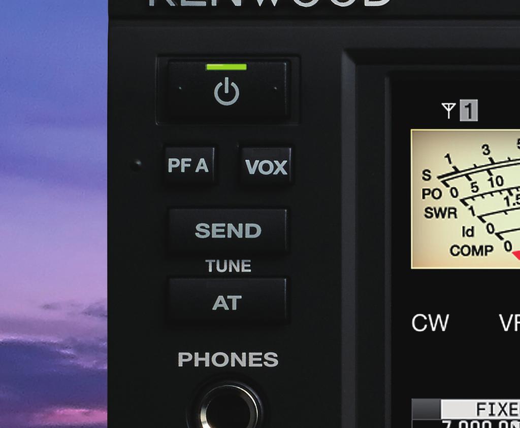
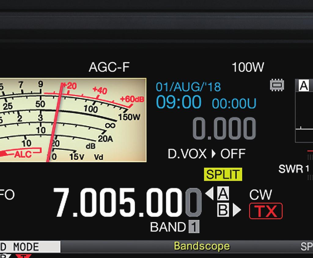
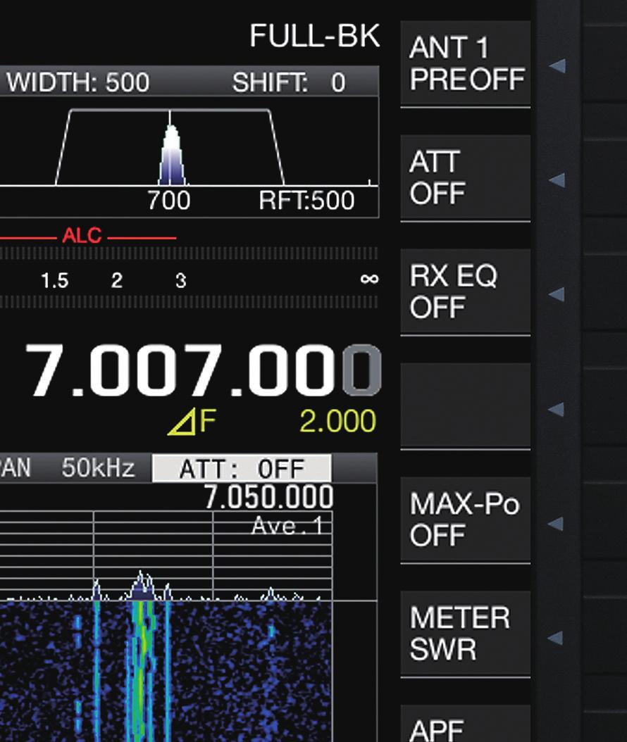
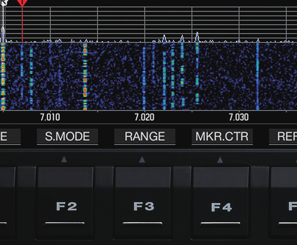
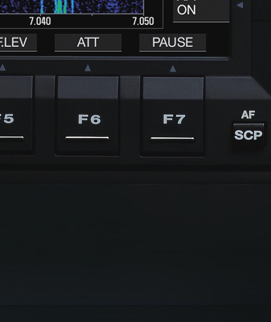
6 The unit carries a high definition 7-inch TFT color display. In addition to a diverse range of display content, the convenient AUTO SCROLL MODE provides strog support for competition or similar operation. Other strengths include clean and stable 100 W* transmitter output, improved quietness from twin cooling fans, and high-speed operation enabled by an auto antenna tuner. *70 MHz band is 50 W LCD Display / Transmit Operational capacity reinforced with CENTER MODE displays and various features The 7-inch TFT color LCD display is the same size as that used in the TS-990S. In addition to basic information including frequency, mode, and S-meter, the band scope and audio scope are also displayed. The TS-890S also displays further improvements in visibility in tough usage scenarios such as competitions. When changing the receive frequency in CENTER MODE, there are many units that display a bright line that flows obliquely over the waterfall, but with the TS-890S, the bright line remains straight and enables tuning operation*. Switching to the follow display is also possible via the menu. *During straight display, the waterfall bright light temporarily stops and undergoes parallel displacement. Image becomes slightly coarse when expanded. With the spectrum scope and waterfall screen display, the analogue meter is simultaneously displayed. The popular sub-scope display from the TS-990S has been incorporated as a filter-scope display. Straight display Follow display Evolved power to perform with diverse displays and auto scroll A band scope providing ease-of-ease FIXED MODE AUTO SCROLL MODE In addition to conventional CENTER MODE and FIXED MODE, the unit comes equipped with an AUTO SCROLL MODE. While in FIXED MODE, if the receive frequency goes over the scope edge, then auto scroll will engage for half a screen width. Furthermore, with the EXPAND function turned on, the screen to be displayed next can be drawn in advance*. Also, with the SHIFT function, the receive marker can be set in the desired position on the vertical grid, which is convenient when displaying a non-receive frequency as the center display, such as for pileups during splits. Screen 1 Screen 2 *Effective in spans under 200 khz. Image becomes slightly coarse when expanded. Screen 3 FIXED MODE allows you to switch between three kinds of display ranges with a single touch of the panel screen. The inital value is preset based on the band plan, but this can be easily adjusted to a desired scope. Improved reference level operability ease-of-use Auto-scroll operation (span 10 khz, EXPAND ON) On the current screen (screen 2), if the frequency is changed to go over the top end of screen 2, it will automatically change to screen 3, and if it goes over the bottom end of screen 2, it will automatically change to screen 1. Waterfall screen creation normally commences, after switching screen, but with the EXPAND function turned to ON, the display switches to the finished screen. -6- The TS-890S has improved operability of the reference level focusing on the visibility of the waterfall. Through optimization of each span, readjustment is mostly unnecessary when switching between them.* Settings are enabled for each band, and readjustment is also unnecessary for the PRE AMP ON and PRE AMP OFF bands. *Spectrum scope waveform height changes during span switching.


 switching, FFT scope / X-Y scope switching on RTTY decode screen, FFT scope / vector scope switching on PSK")


 Transmit spectrum display (during CENTER MODE) SWL display mode Heavy-duty design delivers transmission performance able to withstand long hours of operation Highly reliable 100 W * final-stage")
7 Filter scope display The popular sub-scope from the TS-990S is carried as a filter scope display. You can confirm receive filter selection status, roofing filter bandwidth, IF filter passband information, receive from ex-audio spectrum, CW pitch frequency, and notch frequency all concentrated in one location. Expanded touch operation scope Basic operation of the TS-890S is through knobs and switches with a definite 'clicking' feel rather than touchscreen operation, but the below adjustment features and menu settings can now be changed via touch operation. RX/TX equalizer level adjustment, meter type (analog white / analog black / bar meter) switching, FFT scope / X-Y scope switching on RTTY decode screen, FFT scope / vector scope switching on PSK decode screen, voice-audio fi le playback position change. Furthermore, with touchscreen tuning, in addition to the conventional CW tuning operation via long-push, a short push enables tuning using steps set via MULTI/ CH, while on bands popular with operation in units of 1 khz, practical touch alignment is possible even in CW mode display example SSB. Other display system features SSB mode display example Transmit digital meter enabling display of two kinds of transmit information even during analog meter display Audio scope (spectrum scope, oscilloscope) able to be displayed simultaneously with reduced band scope Band scope IF filter passband with display Change of gradation for waterfall display Frequency marker display function (max. 50) Transmit spectrum display (during CENTER MODE) SWL display mode Heavy-duty design delivers transmission performance able to withstand long hours of operation Highly reliable 100 W * final-stage amplifier circuit The final-stage amplifier device is a Mitsubishi-made MOSFET RDHHF1 (Pch W) operating in push-pull. A MOSFET RD16HHF1 has been used for the drive amp, and a MOSFET RD06HHF1 for the pre-drive amp. Inter-stage matching and fine-tuning delivers superior transmit IMD even for a 13.8 V final ciruit, enabling operation with a clean and lowdistortion signal. *70 MHz band is 50 W. Built-in high-speed automatic antenna tuner enabling high-speed operation The antenna tuner is a preset type also operable during receive and covering amateur bands from 1.8 MHz - 70 MHz. High-speed operation and the proven relay method enable rapid QSY through instantaneous band changing. The menu can be used to set an ON/OFF memory for the antenna tuner for each band. Heavy-duty design with improved quietness The unit employs a twin cooling fan system that uses a pair of 80 x 80 mm fans. Using two fans provides sufficient air flow at low rpm, making for superior quietness. The quietness level for the fans when operating has been improved by more than 5 db compared to our conventional models. Furthermore, the use of an aluminum die-cast chassis combined with a large heat sink makes for a heavy-duty design sufficiently capableof withstanding the tough conditions typical of contests or long hours of hard operation. Other transmit system features 14 MHz transmit IMD example (100 W output) Values are measured examples The position of the heatsink in the center of the rear panel Free settings enabled through linear amp control settings menu A variety of linear amp connections have been taken into account, including self-made ones, and independent settings of various kinds of control at HF/50 MHz, 70 MHz bands are possible. Possible settungs include : linear amp ON/OFF, transmission control (H active, L active), transmission delay ON/OFF, transmission delay time (CW/FSK/PSK) and (SSB/AM/FM), internal relay control, and external ALC threshold voltage adjustment. TCXO as standard, high frequency stability at ±0.1 ppm Equipped with a TCXO (temperature compensated crystal oscillator) requiring no warm-up as standard, high stability of ±0.1 ppm has been obtained in a wide temperature range covering from 0 C ~ +50 C. External standard signal (10 MHz) input is also possible. TCXO temperature drift characteristics Values are measured examples USB keying / SEND DRV connector output (supports transmission in 137 khz and 475 khz bands) Transmit output limiter (supports ON/OFF switching, mode settings) TX tuning - 7 -

 SETTING FEATURE) By connecting another TS-890S or")


8 A variety of features achieve speedy split operation even with a single receiver. Speedy split frequency settings, split status band switching via a band direct key, and support for external TF watch via an external receiver. A panel layout enabling intuitive handling makes for comfortable operation. Control Stronger split-operation handling through VFOA/B SPLIT FREQUENCY SETTINGS KEEPING SPLIT SETTINGS FOR EACH BAND (MENU SETTING FEATURE) SETTING FEATURE) By connecting another TS-890S or TS-590S/SG*1 unit to the ANT OUT connector to use as a sub-receiver*2 and using the split transfer function A, this can enable assistance in 2-wave simultaneous receive during split operation*3. In addition to conventional split frequency setting methods, the TS-990S's proven split setting functions have been included. For 2 khz UP, press '2' on the number pad after a long press of the SPLIT key and the settings are complete. Split frequencies can be set within the range of ± 9 khz (1 khz steps). BAND CHANGING POSSIBLE WHILE SPLIT FREQUENCY RECEIVE VIA EXTERNAL RECEIVER (MENU RX ANT connector Band direct key In the split state, changing the band or band memory via the band direct key will make changes while keeping the split state. Individual settings are possible for the split state. Individual settings are possible for the split frequencies and modes for each band memory, which is convenient for chasing DX-peditions during multiband/ TS-890S COM connector TS-590S/SG IF filter A / B/ C one-touch switching Three kinds of bandwidth presets and 7 MHz band CW 2 khz UP instantaneous switching are possible for IF filters. Switching can also be limited to 2 kinds, so this enables use for wide/ narrow switching. Using the FIL.CLR key, a changed bandwidth can be returned to a preset frequency with a single touch. 14 MHz band SSB 5 khz UP mode operation. SPLIT FREQUENCY CHANGING (MENU SETTING FEATURE) In addition to the conventional method of operating the tuning knob during TF-SET, when RIT/XIT is not in use, the split frequency can also be changed by operating the RIT/XIT knob. Delivering the ultimate in split-operation operability. An interface that thinks of everything Requires a firmware update. *2Loss of approximately 3 db (theoretical value) is experienced. *3Frequency transfer, standby, and sub-receiver audio mute are possible. Requires separate antenna cable and RS-232C cross-cable. Not compatible with combined SP/headphone use. *1-8-

 Compatible with PSK31 (QPSK, BPSK) and PSK63 (BPSK) RTTY/PSK")
.")
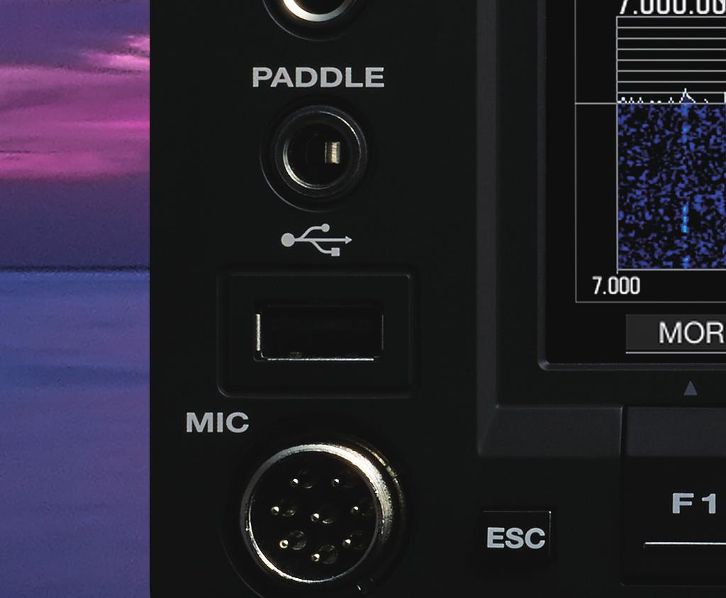
9 CW Morse code decode/encode possible with standalone unit The unit is compatible with CW Morse code decode/encode. Transmission of Morse code is possible with text input from a USB keyboard. Combined use of templates sent from message memories and Morse code transmissions via panel is also possible. Dedicated decode filter switching, and functions for transmission logs and output of decoded text to PC are also included. FSK/PSK functions CW decoder/encoder screen RTTY basic operation settings (keying polarity, shift width, HI/LO tones, reverse mode) Compatible with PSK31 (QPSK, BPSK) and PSK63 (BPSK) RTTY/PSK operation via on-board decoder/encoder (USB keyboard compliant) Message memory function Tuning scope display (audio FFT, waterfall/x-y scope (FSK)/vector scope (PSK)) Compatible with FM operation on 28 MHz, 50 MHz, and 70 MHz bands The unit includes switching to FM narrow for transmit and receive, as well as repeater operation support and FM signaling functionality (CTCSS, cross-tone). DATA mode compatible with external input/output switching Separate from the microphone connector, the back panel includes a variety of I/O interfaces, including analogue audio input and output, USB audio interface, and LAN (VoIP) interface. By combining DATA mode with SSB/FM/AM modes, it is possible to freely set channels for modulation and demodulation. Furthermore, combined use with DATA VOX enables the transmission of modulation signals from a PC, rendering stanby wiring and commands unneccessary. Recording functions The TS-890S comes equipped with a 1 GB internal memory, and can record a maximum of roughly 9 hours audio without using USB memory*. When using USB memory, depending on the capacity, there are no limits on the amount of audio recording. Recording options include normal, constant, and timer, and recording can also be linked to the squelch. *Other fi les sharing memory capacity may result in less than 9 hours. Diverse functions supporting CW operation PADDLE/KEY jack (one each on front/rear, compatible with paddle/ straight key switching) CW auto tuning Full break-in and semi breakin (semi break-in delay time : 50 ms ~ 1000 ms) CW Pitch control, Side tone (pitch frequency liking 5 Hz steps) Built-in electronic keyer (key speed settings, keyer mode A/B selection) 8CH CW message memory function Auto-switch to CW mode on keydown in SSB mode Microphone paddle mode CW auto wait/wait reverse CW reverse mode / CW BFO side band switching Other operation functions, main connectors 120 channel memory XIT shift enabling one-touch transition to split mode from XIT operation Main knob fast-forward CONFIG A/B function enabling overall switching of menu and all settings depending on operation environment Voice guidance function ID beep function notifying callsign transmission guide 3 PF keys Screen capture User screen slideshow screensaver LAN connector USB-A connector (1 each on front/rear) CW auto wait/wait reverse USB-B connector External display connector (DVI-I) KEYPAD jack (add up to 8 external PF keys) External analogue meter output Packet cluster tuning KENWOOD SKY COMMAND II support (When connected to TH-D72E/TM-D710E*/TM-D710GE)** Enables full-duplex operation with improved functionality such as visual confirmation of HF frequency on the LCD panel. Control via TNC (AX.25) enables more accesses to HF functions : XIT, mode switching, splitfrequency operations on/off, memory shift, and frequency step selection. The transporter sends out its pre-programmed call sign via CW every 10 minutes. Remote operation achieved without host PC Direct remote-control function (KNS) When operating using KNS (KENWOOD Network Command System), remote operation of the radio as possible by a direct LAN connection. Conventional connection using a host PC and ARHP (Amateur Radio Host Program) is also possible. USB memory / USB cable firmware update function Starting the unit in update mode and inserting a USB memory stick containing firmware into the front USB-A port will start an automatic update. Updates can also be carried out by connecting the TS-890S to a PC via a USB cable, and moving a firmware file using drag & drop on top of the 'TS-890S' removable device that is displayed on the PC's desktop during update mode. *Discontinued product. **KENWOOD SKY COMMAND II uses a pair of TH-D72E or TM-D710E*/TM-D710GE transceivers. Note: Refer to applicable Amateur Radio regulations to check whether you are permitted to use this function
![Front Panel Front / Back Panel Front Panel Back Panel [1] [PHONES] Jack - Ø 6.](/docs-images/93/113526566/images/10-0.jpg "3: for connecting headphones [1] [ANT1, ANT2] Antenna connectors M-type x 2 [11]")
![[USB-A] Connector: for USB memory, USB keyboard [2] [PADDLE] Jack - Ø6.](/docs-images/93/113526566/images/10-1.jpg "3: for connecting CW operation paddle [2] [AT] Connector - 6-pin: for connecting")
![external antenna tuner [12] [GND] Terminal: for connection of Earth [3] [USB-A]](/docs-images/93/113526566/images/10-2.jpg "Connector: for USB memory, USB keyboard [3] [RX IN] Connector - RCA: for connecting")
![receive only antenna [13] [KEY] Jack - Ø 6.](/docs-images/93/113526566/images/10-3.jpg "3: for paddle, straight key, and PC keying [4] [MIC] Connector - 8-pin metal type: for")
![connecting microphone [4] [RX OUT] Connector - RCA: for connecting external receiver](/docs-images/93/113526566/images/10-5.jpg "[14] [ACC2] connector - 13-pin DIN: for connection of audio I/O & other acc.")
![[5] [DRV] Connector: drive output [15] [REMOTE] connector - 7-pin DIN: for connection](/docs-images/93/113526566/images/10-6.jpg "of linear amplifier Back Panel [6] [ANT OUT]Connector: for antenna signal [16] [METER]")

![13.8 V] Connector - 4-pin: [17] [EXT.](/docs-images/93/113526566/images/10-8.jpg "SP] 5: for connection of DC Power Source for connection of external speakers [8] [REF")
![IN - 10 MHz] Connector - BNC: [18] [USB-B] Connector: for standard external sigal](/docs-images/93/113526566/images/10-9.jpg "input for PC control, USB audio [9] [KEYPAD] Jack - Ø3.")
![5: [19] [DISPLAY] Connector - DVI-I: for connection of external PF key for connection](/docs-images/93/113526566/images/10-10.jpg "of external display [10] [COM] Connector D-Sub - 9-pin: [20] [LAN] Connector - RJ-45:")


 NEW Software to use on the host side when controlling")
10 Front Panel Front / Back Panel Front Panel Back Panel [1] [PHONES] Jack - Ø 6.3: for connecting headphones [1] [ANT1, ANT2] Antenna connectors M-type x 2 [11] [USB-A] Connector: for USB memory, USB keyboard [2] [PADDLE] Jack - Ø6.3: for connecting CW operation paddle [2] [AT] Connector - 6-pin: for connecting external antenna tuner [12] [GND] Terminal: for connection of Earth [3] [USB-A] Connector: for USB memory, USB keyboard [3] [RX IN] Connector - RCA: for connecting receive only antenna [13] [KEY] Jack - Ø 6.3: for paddle, straight key, and PC keying [4] [MIC] Connector - 8-pin metal type: for connecting microphone [4] [RX OUT] Connector - RCA: for connecting external receiver [14] [ACC2] connector - 13-pin DIN: for connection of audio I/O & other acc. [5] [DRV] Connector: drive output [15] [REMOTE] connector - 7-pin DIN: for connection of linear amplifier Back Panel [6] [ANT OUT]Connector: for antenna signal [16] [METER] Jack - Ø 3.5: for connection distributon to external receiver of commercial analog meters [7] [DC 13.8 V] Connector - 4-pin: [17] [EXT. SP] Jack - Ø 3.5: for connection of DC Power Source for connection of external speakers [8] [REF IN - 10 MHz] Connector - BNC: [18] [USB-B] Connector: for standard external sigal input for PC control, USB audio [9] [KEYPAD] Jack - Ø3.5: [19] [DISPLAY] Connector - DVI-I: for connection of external PF key for connection of external display [10] [COM] Connector D-Sub - 9-pin: [20] [LAN] Connector - RJ-45: for PC control for PC control (KNS) Main options SP-890 YG-82CN-1 External Speaker The SP-890 has a design that matches the TS-890S and achieves a frequency response with good intelligibility. Through the use of high-cut and low-cut filters, the reciev sound is at a basic setting that allows the adjustment of its timbre to suit your preferences. MC-90 MC-60S8 ARCP-890 ARHP-890 Deluxe Desktop Microphone Desktop Microphone Software Radio Control Program Software Radio Host Program MC-43S HS-5 Hand Microphone Open-Air Headphone NEW HS-6 PS-60 Lightweight Headphone Stable Power Supply A narrow-band roofing filter that removes ultra adjacent interference signals. 70 Hz CW Filter NEW NEW Software to control your TS-890S remotely from your PC. Band scope can also be used for KNS operation. (LAN connection recommended) NEW Software to use on the host side when controlling your TS-890S remotely over a network. ARUA-10 ARVP-10 Ver & later Software USB Audio Controller Ver & later Software VoIP Program Software to se the speakers and microphone of a PC connected by a USB cable in place of the radio unit's speaker and microphone. Software to relay voice-audio between a host-side radio and remote-side PC connected over a network through the KENWOOD Network Command System.
11 GENERAL SPECIFICATIONS Frequency Range (transmitter) Frequency Range (receiver) Mode Frequency Stability Antenna Impedance Antenna Tuner Load Range 160 m band 1.81 ~ 2.0 MHz 80 m band 3.5 ~ 3.8 MHz 60 m band * ~ 5.45 MHz 40 m band 7.0 ~ 7.2 MHz 30 m band 10.1 ~ MHz 20 m band 14.0 ~ MHz 17 m band ~ MHz 15 m band 21.0 ~ MHz 12 m band ~ MHz 10 m band 28.0 ~ 29.7 MHz 6 m band 50.0 ~ 52.0 MHz 4 m band 70.0 ~ 70.5 MHz 0.13 ~ 30 MHz, 50 ~54 MHz, 70.0 ~ 70.5 MHz VFO: continuous 30 khz ~ 74.8 MHz A1A (CW), A3E (AM), J3E (SSB), F1B (FSK), F3E (FM), G1B (PSK) ±0.1 ppm, 0 C ~ +50 C 50 Ω 16.7 Ω ~ 150 Ω Supply Voltage DC 13.8 V ±15% Ground Negative ground Current Drain TX 22.5 A or less Operating Temperature Dimensions (W x H x D) Weight RX (no signal) without projections with projections SPECIFICATIONS TRANSMITTER Output Power (AM) Modulation HF / 50 MHz Maximum Frequency Deviation (FM): Spurious Emissions Carrier Suppression Unwanted Sideband Suppression Transmit Frequency Response Microphone Impedance XIT Variable Range 2.5 A or less 0 C ~ +50 C x x mm x x mm Approx kg max. 100 W / min. 5 W (max. 25 W / min. 5 W) 70 MHz max. 50 W / min. 5 W (max W / min. 5W) SSB: Balanced, AM: Low Power, FM: Reactance Wide: ±5 khz or less, Narrow: ±2.5 khz or less HF: -50 db or less 50 MHz: -63 db or less 70 MHz: -60 db or less 60 db or more 60 db or more Within -6 db (100 ~ 2900 Hz) 600 Ω ±9.999 khz SPECIFICATIONS RECEIVER Circuit Type Intermediate Frequency 1st IF 2nd IF Sensitivity (TYP) SSB / CW / FSK / PSK (S/N 10 db) Squelch Sensitivity AM (S/N 10 db) FM (12 db SINAD) SSB / CW / FSK / AM FM Image Rejection Ratio IF Rejection Ratio Double Superheterodyne MHz 24 khz / 36 khz (FM) 0.5 μv (0.13 ~ MHz) 4 μv (0.522 ~ MHz) 0.2 μv (1.705 ~ 24.5 MHz) 0.13 μv (24.5 ~ 30 MHz) 0.13 μv (50 ~ 54 MHz) 0.13 μv (70 ~ 70.5 MHz) 6.3 μv (0.13 ~ MHz) 31.6 μv (0.522 ~ MHz) 2 μv (1.705 ~ 24.5 MHz) 1.3 μv (24.5 ~ 30 MHz) 1.3 μv (50 ~ 54 MHz) 1.3 μv (70 ~ 70.5 MHz) 0.22 μv (28 ~ 30 MHz) 0.22 μv or less (50 ~ 54 MHz) 0.22 μv or less (70 ~ 70.5 MHz) 5.6 μv or less (0.13 ~ MHz) 18 μv or less (0.522 ~ MHz) 1.8 μv or less (1.705 ~ 30 MHz) 1.1 μv or less (50 ~ 54 MHz) 1.1 μv or less (70 ~ 70.5 MHz) 0.2 μv or less (28 ~ 30 MHz) 0.2 μv or less (50 ~ 54 MHz) 0.2 μv or less (70 ~ 70.5 MHz) HF: 70 db or more 50/70 MHz: 60 db or more 70 db or more Selectivity SSB 2.6 khz or more (-6 db) RIT Variable Range CW / FSK AM FM Notch Filter Attenuation Beat Cancel Attenuation 4.4 khz or less (-60 db) 500 Hz or more (-6 db) 1.2 khz or less (-60 db) 6.0 khz or ore (-6 db) 12 khz or less (-50 db) 12 khz or more (-6 db) 25 khz or less (-50 db) ±9.999kHz 60 db or more (Auto), 70 db or more (Manual) 40 db or more Audio Output 1.5 W or more (8 Ω) Audio Output Impedance 4 Ω ~ 8 Ω *1 60m band: refer to applicable Amateur Radio regulations to your country. Electronic specifi cations apply only to amateur bands. Receive sensitivity drops in the vicinity of the 1st IF frequency (8.248 MHz) due to IF trapping. Internal beat may occur during amateur band receive. Band scope (waterfall) screen may also display spurious signals other than recieve signal. Supplied accessories DC power cord x 1 7-pin DIN plug (for remote connector x 1) 13-pin DIN plug (for ACC2 connector x 1) Spare fuse 25 A x 1 Operation manuel x 1 Warranty card x

12 KENWOOD SKY COMMAND SYSTEM II is a registered trademark of JVCKENWOOD Corporation in the U.S. JVCKENWOOD follows a policy of continuous advancement in development. For this reason, specifications may be changed without notice. *Alterations may be made without notice to improve the ratings or the design of the transceiver. *The photographic and printing processes may cause the coloration of the transceiver to appear different from that of the actual transceiver. JVCKENWOOD Belgium NV comms@be.jvckenwood.com CA-336E-E-12
For DX Enthusiasts. JVCKENWOOD U.K. Limited 12 Priestley Way, London, NW2 7BA, United Kingdom. HF/50MHz/70MHz TRANSCEIVER
 HF/50MHz/70MHz TRANSCEIVER For DX Enthusiasts KENWOOD SKY COMMAND SYSTEM II is a registered trademark of JVCKENWOOD Corporation in the U.S. JVCKENWOOD follows a policy of continuous advancement in development.
HF/50MHz/70MHz TRANSCEIVER. For DX Enthusiasts. HF/50MHz/70MHz TRANSCEIVER TS-890S
 HF/50MHz/70MHz TRANSCEIVER For DX Enthusiasts HF/50MHz/70MHz TRANSCEIVER TS-890S 2 Performance Exceeding Expectations. The most rewarding results often take place when faced with the harshest and most
For DX Enthusiasts. HF/50MHz TRANSCEIVER. 3 rd IMDR 110dB. RMDR 122dB. BDR 150dB
 HF/50MHz TRANSCEIVER 3 rd IMDR 110dB RMDR 122dB BDR 150dB * * * For DX Enthusiasts KENWOOD SKY COMMAND SYSTEM II is a registered trademark of JVCKENWOOD Corporation in the U.S. JVCKENWOOD follows a policy
TS-590SG HF/ 50MHz All-Mode TRANSCEIVER_
 New Product Release Information Oct 2014 TS-590SG HF/ 50MHz All-Mode TRANSCEIVER_ Kenwood introduces Updated to new G version new HF/50MHz All-Mode Transceiver Four years ago we launched our best-selling
The amazing evolution of the 706 series
 The amazing evolution of the 706 series The IC-706MKIIG carries on the 706 series tradition of base station performance and features in a mobile reg-sized package. Building on this legacy, frequency coverage
SPECS FEATURES SUPPLIED ACCESSORIES. HF All Band Transceiver
 718 HF All Band Transceiver RX 0.030-29.999999MHz* TX 1.800-1.999999 MHz** 3.500-3.999999 MHz** 7.000-7.300000 MHz 10.100-10.150000 MHz 14.000-14.350000 MHz 18.068-18.168000 MHz 21.000-21.450000 MHz 24.890-24.990000
Icom IC-9100 HF/VHF/UHF transceiver
 263 Walsall Road, Great Wyrley, Walsall, WS6 6DL Established 1997. Open Monday - Friday 9am - 5pm and Saturday 9.30am - 4pm Tel: 01922 414 796 Fax: 01922 417829 Skype: radioworld_uk Icom IC-9100 HF/VHF/UHF
The Icom IC Adam Farson VA7OJ. A New Top-class HF/6m Transceiver. IC-7700 Information & Links
 The Icom IC-7700 A New Top-class HF/6m Transceiver Adam Farson VA7OJ IC-7700 Information & Links Copyright 2008 North Shore Amateur Radio Club NSARC HF Operators IC-7700 1 IC-7700 front panel This is a
Peerless Performance TS-590S. HF / 50 MHz ALL MODE TRANSCEIVER
 Peerless Performance TS-590S HF / 50 MHz ALL MODE TRANSCEIVER Discovering the Hidden The TS-590S marks a bold new chapter in Kenwood s proud history of high-performance HF transceivers. Featuring a narrow-band
Peerless Performance TS-590S. HF / 50 MHz ALL MODE TRANSCEIVER
 Peerless Performance HF / 50 MHz ALL MODE TRANSCEIVER Discovering the Hidden The marks a bold new chapter in Kenwood s proud history of high-performance HF transceivers. Featuring a narrow-band Roofing
JVCKENWOOD Belgium NV
 JVCKENWOOD Belgium NV *Alterations may be made without notice to improve the ratings or the design of the transceiver. *The photographic and printing processes may cause the coloration of the transceiver
Pushing performance to the pinnacle
 Pushing performance to the pinnacle The latest DSP technologies developed for the IC-7800/7700 plus over 45 years of analog circuit expertise give the IC-7600 the performance advantage. The flagship's
December A top of the line transceiver with ultimate receiver performance
 December 2007 HF/50MHz TRANSCEIVER i7700 A top of the line transceiver with ultimate receiver performance To claim the right of being a top of the line transceiver, it is necessary to have the absolute
Second Hand Yaesu FTDX5000MP HF base station transceiver
 263 Walsall Road, Great Wyrley, Walsall, WS6 6DL Established 1997. Open Monday - Friday 9am - 5pm and Saturday 9.30am - 4pm Tel: 01922 414 796 Fax: 01922 417829 Skype: radioworld_uk Second Hand Yaesu FTDX5000MP
HF/50MHz TRANSCEIVER
 HF/50MHz TRANSCEIVER D isplay Pushing performance to the pinnacle The latest DSP technologies developed for the flagship models plus many decades of analog circuit expertise give the the performance advantage.
GRAND STRAND AMATEUR RADIO CLUB
 The GRAND STRAND AMATEUR RADIO CLUB (GSARC) Myrtle Beach SC is offering used amateur related equipment for sale. Written bids may be submitted to the GSARC up to Friday, November 23 rd, 2018. Only currently
i7610 Technical Report Volume 1
 i7610 Technical Report Volume 1 ~ Profile ~ Outstanding HF Experience Right Here Icom s mid class HF transceivers evolved especially with the IC-756, IC- 756PRO and IC-7600, and were technology leaders
i7610 Technical Report Volume 1
 i7610 Technical Report Volume 1 ~ Profile ~ Outstanding HF Experience Right Here Icom s mid class HF transceivers evolved especially with the IC-756, IC756PRO and IC-7600, and were technology leaders in
Elmer Session Hand Out for 3/3/11 de W6WTI. Some Common Controls Found On Amateur Radio Transceivers. (From ARRL web site tutorial)
") Elmer Session Hand Out for 3/3/11 de W6WTI Some Common Controls Found On Amateur Radio Transceivers. (From ARRL web site tutorial) The placement of the controls may vary from manufacturer to manufacturer
Elmer Session Hand Out for 3/3/11 de W6WTI Some Common Controls Found On Amateur Radio Transceivers. (From ARRL web site tutorial) The placement of the controls may vary from manufacturer to manufacturer
IC-F7000. Advanced selective call and ALE make HF communication easier than ever!
 Page 1 of 5 HF TRANSCEIVER IC-F7000 Advanced selective call and ALE make HF communication easier than ever! The IC-F7000 is an HF land mobile transceiver especially designed forlong distance communications.
Technician License Course Chapter 5. Lesson Plan Module 11 Transmitters, Receivers and Transceivers
 Technician License Course Chapter 5 Lesson Plan Module 11 Transmitters, Receivers and Transceivers Generalized Transceiver Categories Mobile Single Band Dual Band All Band Multimode Handheld (HT) VHF/UHF
LnR Precision, Inc. 107 East Central Avenue, Asheboro, NC
 LD5 CW/SSB QRP Transceiver Quick guide manual Description: At the development base of the digital signal processing unit, an algorithm is embedded for IQ processing of the channels with phase suppression
About This Manual. Copyright. Copyright of this Manual and Software. Firmware Copyright. Trademarks and Intellectual Properties. Other Restrictions
 About This Manual This in-depth manual is intended to explain the features of the TS-590SG and its convenient use. In addition to those who have purchased or are considering the purchase of the TS-590SG,
HF Transceiver TS-570S(G) HF+6m Transceiver
 HF+6m Transceiver") TS-570D(G) HF Transceiver TS-570S(G) HF+6m Transceiver Advanced Digital Technology for Everyone Kenwood has brought the best of HF DSP technology out of the clouds and into the hands of everyone with the
TS-570D(G) HF Transceiver TS-570S(G) HF+6m Transceiver Advanced Digital Technology for Everyone Kenwood has brought the best of HF DSP technology out of the clouds and into the hands of everyone with the
TS-590S ADJUSTMENT. Updating the Firmware. Required Test Equipment. Preparation
 Updating the Firmware The firmware of the main MCU and DSP can be updated using the TS590 Update update software. Update the firmware according to the procedure displayed in update software. Refer to the
LD5 CW/SSB QRP Transceiver SDR /DSP
 LD5 CW/SSB QRP Transceiver SDR /DSP Quick guide manual Description: At the development base of the digital signal processing unit, an algorithm is embedded for IQ processing of the channels with phase
ICOM IC-R8600 Specifications, Features & Options
 General Frequency coverage IC-R8600 USA: 0.010000 821.999999MHz*, 851.000000 866.999999MHz, 896.000000 3000.000000MHz (*Guaranteed range: 0.100000 821.999999MHz) Antenna connector Frequency stability Mode
Module 8 Theory. dbs AM Detector Ring Modulator Receiver Chain. Functional Blocks Parameters. IRTS Region 4
 Module 8 Theory dbs AM Detector Ring Modulator Receiver Chain Functional Blocks Parameters Decibel (db) The term db or decibel is a relative unit of measurement used frequently in electronic communications
i2820h (USA) ie2820(europe)
 ie2820(europe)") January 2007 DUAL BAND TRANSCEIVERS i2820h (USA) ie2820(europe) The above photo shows the IC-2820H. The IC-E2820 differs slightly from this photo. Icom proudly announces the debut of the new dual band
January 2007 DUAL BAND TRANSCEIVERS i2820h (USA) ie2820(europe) The above photo shows the IC-2820H. The IC-E2820 differs slightly from this photo. Icom proudly announces the debut of the new dual band
RF Direct Sampling Takes You to the Next Level
 HF/50MHz TRANSCEIVER RF Direct Sampling Takes You to the Next Level Outstanding HF Experience Right Here RF Direct Sampling Takes You to the Next Level with Advanced RMDR and True Dual Receive Whether
KENWOOD SKY COMMAND SYSTEM
 KENWOOD SKY COMMAND SYSTEM Operation Manual KENWOOD COMMINICATIONS CORPORATION KENWOOD COMMUNICATIONS CORPORATION This operation manual is used for the KENWOOD SKY COMMAND SYSTEM (hereinafter referred
Distinctive Performance TS-590S HF/50 MHz ALL MODE TRANSCEIVER
 Distinctive Performance TS-590S HF/50 MHz ALL MODE TRANSCEIVER ABOUT THIS MANUAL This in-depth manual is intended to explain the features of the TS-590S and its convenient use. We hope that this manual,
Four 32-bit floating point DSP units +40dBm ultra high intercept point
 Icom has been the world pioneer in amateur radio for 40 years. The first to bring transistor technology, digital PLL technology and the latest DSP technology to name a few achievements. It is therefore
HF Receivers, Part 3
 HF Receivers, Part 3 Introduction to frequency synthesis; ancillary receiver functions Adam Farson VA7OJ View an excellent tutorial on receivers Another link to receiver principles NSARC HF Operators HF
MC-80 TERMINAL INTERFACES
 DATA COMMUNICATOR 144/440MHz FM Dual Bander One of the greatest pleasures of exploration is being able to communicate each new discovery. And Kenwood s Data Communicator allows you to do just that. This
Development of the QSX transceiver kit
 Development of the QSX transceiver kit Norfolk Amateur Radio Club Wednesday 9-Jan-2019 Hans Summers, G0UPL http://qrp-labs.com QCX 5W CW transceiver kit QRP Labs CW Xcvr Introduced at YOTA 2017 summercamp
TS-590S TS-590SG. PC CONTROL COMMAND Reference Guide
 TS-590S TS-590SG PC CONTROL COMMAND Reference Guide January/30/2019 PC CONTROL COMMAND REFERENCE GUIDE ABOUT THIS REFERENCE GUIDE All descriptions in this reference guide are for the user s convenience.
Icom IC-7851 HF & 50MHz transceiver
 Icom IC-7851 HF & 50MHz transceiver A new flagship is born: the current market leader in terms of performance 36 PHOTO 1: IC-7851 front view. INTRODUCTION. In 2004, Icom launched their IC-7800 top-of-the-range
From 40 years of RF design expertise comes the Masterpiece Ham Radio Transceiver
 From 40 years of RF design expertise comes the Masterpiece Ham Radio Transceiver Icom is a pioneer in the amateur radio world. Starting with the first analog PLL circuit in the IC-200 to the ground-breaking
STORING MESSAGES Note: If [MEMORY] (F5) is unavailable in the function key guide, press [MORE] (F2). An alternate key guide will appear.
![STORING MESSAGES Note: If [MEMORY] (F5) is unavailable in the function key guide, press [MORE] (F2). An alternate key guide will appear.](/thumbs/92/107920661.jpg "STORING MESSAGES Note: If [MEMORY] (F5) is unavailable in the function key guide, press [MORE] (F2). An alternate key guide will appear.") ASSISTING YOUR SMOOTH QSO 5 If letters not transmitted yet remain in the text string buffer when [F12] is pressed at step 6, "WAIT" appears on the status bar. When the entire text string is transmitted,
ASSISTING YOUR SMOOTH QSO 5 If letters not transmitted yet remain in the text string buffer when [F12] is pressed at step 6, "WAIT" appears on the status bar. When the entire text string is transmitted,
DX AM FM SSB CW PA Amateur Base Station Transceiver OWNER S MANUAL RX / TX 2 4 POWER NF CHANNEL MODE RF POWER OFF CAL OFF OFF CALIBRATE
 1 2 3 6 4050 ULA 6070 TI 80 90 100 9 DX 2517 2517 RX / TX 0 2 4 SWR WATTS SET 81012 22 1 010 3 2030 5 MOD 7 ON dbover 9 SIGNAL +20 +40+60 PA FM AM USB LSB CW POWER ON SWR NB / ANL R.BEEP +10KHz NF CHANNEL
Technician License Course Chapter 3 Types of Radios and Radio Circuits. Module 7
 Technician License Course Chapter 3 Types of Radios and Radio Circuits Module 7 Radio Block Diagrams Radio Circuits can be shown as functional blocks connected together. Knowing the description of common
FT-897 Alignment. Local Oscillator Adjustment. PLL Adjustment
 FT-897 Local Oscillator Adjustment Reference Frequency Adjustment a. Connect a frequency counter to TP1032. b. Adjust the trimmer capacitor (TC5001) for 67.875000MHz ±5Hz on the frequency counter. c. Connect
Transceiver selection and Specs.
 Transceiver selection and Specs. Transceivers 1956-2018 From TUBES to SDR Covers 20-10 meters in 100Khz segments, 10 available, crystal needed for each. Plug in crystal holder. 100 Watts output, final
QUICK REFERENCE GUIDE
 QUICK REFERENCE GUIDE Installation 1. Install a ground system for DC noise suppression and RFI suppression 2. Install your DC power supply 3. Install lightning protection. This will help protect more than
TMR6200 HF Naval Digital Transceivers
 TMR6200 HF Naval Digital Transceivers One or Two High Performance 500 W/1 kw Transceivers in a Single Cabinet 125 W High Performance Transceiver In a 4U/19-inch Chassis Outstanding RF Performance Optimized
HF TRANSCEIVER V1.0. Copyright 2014, XIEGU, Inc. All Rights Reserved
 HF TRANSCEIVER V1.0 Copyright 2014, XIEGU, Inc. All Rights Reserved Table of Contents I. Introduction equipment Second, the device description Third, the operating instructions Four, advanced menu settings
INSTALLATION AND CONNECTIONS Section 2
 STLLTION ND CONNECTIONS Section Unpacking - ntenna jumper cable connection - Selecting a location - Rack mounting handle attachment - Grounding -3 ntenna connection -3 CF (Compact Flash) memory card -3
TABLE OF CONTENTS TABLE OF CONTENTS 1
 TABLE OF CONTENTS TABLE OF CONTENTS 1 Chapter 1 YOUR NEW ORION II ORION II ANOTHER STEP FORWARD IN TEN-TEC INNOVATION 4 UNPACKING YOUR NEW ORION II 4 ABOUT THIS MANUAL 4 CONNECTING A POWER SUPPLY 5 A WORD
TS-890S. PC CONTROL COMMAND Reference Guide
 TS-890S PC CONTROL COMMAND Reference Guide August/30/2018 PC CONTROL COMMAND REFERENCE GUIDE ABOUT THIS REFERENCE GUIDE All descriptions in this reference guide are for the user s convenience. JVC KENWOOD
SUBELEMENT T4. Amateur radio practices and station set up. 2 Exam Questions - 2 Groups
 SUBELEMENT T4 Amateur radio practices and station set up 2 Exam Questions - 2 Groups 1 T4A Station setup: connecting microphones; reducing unwanted emissions; power source; connecting a computer; RF grounding;
Using measurement methods described in Australian/New Zealand Standard AS/NZS 4770:2000
 Barrett 2050 HF transceiver Using measurement methods described in Australian/New Zealand Standard AS/NZS 4770:2000 General Specifications Equipment Standards Transmit frequency range Receive frequency
E L E C R A F T K 2 R E V I S I O N 2 F I R M W A R E
 E L E C R A F T K 2 R E V I S I O N 2 F I R M W A R E Installation and Reference Manual Rev. B, August 28, 2001 Summary of Changes... 2 Computer Control (KIO2)... 2 Transverter Bands... 2 RTTY/Data Mode
GENERAL CATALOG
 GENERAL CATALOG AMATEUR RADIO EQUIPMENT 2000 H F T R A N S C E I V E R S TS-950SDX 160m to 10m amateur band operation, 100kHz to 30MHz general coverage receiver Built-in DSP (Digital Signal Processing)
: Triple PLL, lowest reference frequency 10 khz. : ± 5 khz in 10 Hz steps, synthesized.
 PETER DE CONINCK HAGENUK RX 1001MVB RECEIVER ONL4234 SERIAL N 5820-310-6162 BELGIAN SWL DRAWING N 97 8 2.164 Technical data Frequency range Frequency resolution Frequency tuning Frequency synthesizer Frequency
INSTRUCTION MANUAL. HF/ 50 MHz ALL MODE TRANSCEIVER TS-590S
 INSTRUCTION MANUAL HF/ 50 MHz ALL MODE TRANSCEIVER TS-590S NOTIFICATION This equipment complies with the essential requirements of Directive 1999/5/EC. The use of the warning symbol means the equipment
Technical Equipment Specification
 STATE OF CALIFORNIA Office of the State Chief Information Officer Public Safety Communications Division Technical Equipment Specification Equipment Type: Transmitter/Receiver Mobile Relay/Base/Control
Icom IC A Look Under the Hood Bruce Wampler - WA7EWC
 Icom IC-7300 A Look Under the Hood Bruce Wampler - WA7EWC The Icom IC-7300 is a brand new (April 2016), Direct Conversion, 100% SDR. It is the first SDR amateur radio transceiver by one of the major Japanese
GETTING THE MOST FROM YOUR HF TRANSCEIVER FRED KEMMERER, AB1OC JANUARY 10 TH, 2017
 GETTING THE MOST FROM YOUR HF TRANSCEIVER FRED KEMMERER, AB1OC JANUARY 10 TH, 2017 Topics Its mostly about the receiver Transmitter/amplifier operation tips and tricks Common operating scenarios Not to
Kenwood TS-590S Peter Hart reviews the latest HF & 50MHz transceiver
 RADCOM JANUARY 2011 PETER HART, G3SJX E-MAIL: PETER@G3SJX.FREESERVE.CO.UK Kenwood TS-590S Peter Hart reviews the latest HF & 50MHz transceiver PHOTO 1: General view of the Kenwood TS-590S. INTRODUCTION.
IC-756 Pro III vs. Pro II
 IC-756 Pro III vs. Pro II Improvements in the Pro III vs. the Pro II Adam Farson VA7OJ IC-756Pro3 Information & Links Copyright 2006 North Shore Amateur Radio Club NSARC HF Operators 756Pro3 vs. Pro2 1
UNIVERSAL-DDS-VFO UDV ( 1 Hz to 10 MHz)
") UNIVERSAL-DDS-VFO UDV ( 1 Hz to 10 MHz) Connection and operating instructions 1. Introduction The UDV is the ideal device to adapt older, VFO-controlled transceivers to modern requirements regarding frequency
UNIVERSAL-DDS-VFO UDV ( 1 Hz to 10 MHz) Connection and operating instructions 1. Introduction The UDV is the ideal device to adapt older, VFO-controlled transceivers to modern requirements regarding frequency
INSTRUCTION MANUAL ALL MODE MULTI-BAND TRANSCEIVER TS-2000 TS-2000X TS-B2000
 B6--50 (K, E) 09 08 07 06 05 ALL MODE MULTI-BAND TRANSCEIVER TS-000 TS-000X TS-B000 INSTRUCTION MANUAL NOTIFICATION This equipment complies with the essential requirements of Directive 999/5/EC. The use
Operating Station Equipment
 Amateur Radio License Class Operating Station Equipment Presented by Steve Gallafent October 3, 2007 Operating Station Equipment Modulation Modulation is the process of adding information to a radio signal
FREQUENCY SYNTHESIZERS, SIGNAL GENERATORS
 SYNTHESIZED SIGNAL GENERATOR MG3641A/MG3642A 12 khz to 1040/2080 MHz NEW New Anritsu synthesizer technology permits frequency to be set with a resolution of 0.01 Hz across the full frequency range. And
THE TRANSCEIVER Instruction Manual
 THE TRANSCEIVER i7800 Instruction Manual A-6328H-1EX-q Printed in Japan 2004 Icom Inc. FOREWORD Congratulations! You are the owner of the world s most advanced amateur HF/50 MHz transceiver IC-7800. The
HF Receivers, Part 2
 HF Receivers, Part 2 Superhet building blocks: AM, SSB/CW, FM receivers Adam Farson VA7OJ View an excellent tutorial on receivers NSARC HF Operators HF Receivers 2 1 The RF Amplifier (Preamp)! Typical
ADJUSTING YOUR HF RECEIVER
 ADJUSTING YOUR HF RECEIVER N5KIP January 31, 2017 Disclaimers What works on one model of radio might not work well on another CW (narrow bandwidth) and SSB (wider bandwidth) will require different receiver
Technician Licensing Class. Lesson 4. presented by the Arlington Radio Public Service Club Arlington County, Virginia
 Technician Licensing Class Lesson 4 presented by the Arlington Radio Public Service Club Arlington County, Virginia 1 Quiz Sub elements T6 & T7 2 Good Engineering Practice Sub element T8 3 A Basic Station
evolution wireless G4 ew 100 G4-835-S ew 100 G4-845-S ew 100 G4-865-S Vocal Set
 1/7 Versatile wireless systems for those who sing, speak or play instruments with up to 42 MHz tuning bandwidth in a stable UHF range and fast, simultaneous setup of up to 12 linked systems. State-of-the-art
LBI-31564A. Mobile Communications. DELTA - SX MHz RADIO COMBINATIONS (NEGATIVE GROUND ONLY) Maintenance Manual
 Maintenance Manual") A Mobile Communications DELTA - SX 136-174 MHz RADIO COMBINATIONS (NEGATIVE GROUND ONLY) Maintenance Manual TABLE OF CONTENTS MILITARY AND SYSTEM SPECIFICATIONS................................. 2-3 COMBINATION
A Mobile Communications DELTA - SX 136-174 MHz RADIO COMBINATIONS (NEGATIVE GROUND ONLY) Maintenance Manual TABLE OF CONTENTS MILITARY AND SYSTEM SPECIFICATIONS................................. 2-3 COMBINATION
Lesson 2 HF Procedures and Practices Overview
 Lesson 2 HF Procedures and Practices Overview On Display QSL Cards On Display Icom IC-7000 On Display Buxcomm Rascal Sound card interface: PSK31 SSTV RTTY Packet Digital Voice MFSK16 -more- Operating Techniques
evolution wireless G4 ew 100 G4-ME2 ew 100 G4-ME4 Lavalier Set
 1/7 Versatile wireless systems for those who sing, speak or play instruments with up to 42 MHz tuning bandwidth in a stable UHF range and fast, simultaneous setup of up to 12 linked systems. The perfect
Barrett 950 HF transceiver specifications Using measurement methods described in European Telecommunication Standard
 Barrett 950 HF transceiver specifications Using measurement methods described in European Telecommunication Standard 300 373. General Specifications Equipment Standards Transmit frequency range Receive
FTV-1000 Operating Manual
 50MHz Transverter FTV-1000 Operating Manual FTV-1000 Operating Manual VERTEX STANDARD CO., LTD. 4-8-8 Nakameguro, Meguro-Ku, Tokyo 153-8644, Japan VERTEX STANDARD US Headquarters 10900 Walker Street, Cypress,
Maintenance Manual. MTD SERIES 900 MHz, 10-WATT, DATA ONLY MOBILE RADIO. Mobile Communications LBI TABLE OF CONTENTS
 Mobile Communications MTD SERIES 900 MHz, 10-WATT, DATA ONLY MOBILE RADIO TABLE OF CONTENTS RF BOARD............................... LBI-38545 AUDIO BOARD............................ LBI-38546 LOGIC BOARD............................
KWM-2/2A Transceiver THE COLLINS KWM-2/2A TRANSCEIVER
 KWM-2/2A Transceiver Click the photo to see a larger photo Click "Back" button on browser to return Courtesy of Norm - WA3KEY THE COLLINS KWM-2/2A TRANSCEIVER Unmatched for versatility, dependability and
TS-590S INSTRUCTION MANUAL. HF/ 50 MHz ALL MODE TRANSCEIVER
 INSTRUCTION MANUAL HF/ 50 MHz ALL MODE TRANSCEIVER TS-590S NOTIFICATION This equipment complies with the essential requirements of Directive 1999/5/EC. The use of the warning symbol means the equipment
TC-3000C Bluetooth Tester
 TC-3000C Bluetooth Tester Product Instructions TC-3000C Bluetooth Tester is able to analyze the data of every packet that is transmitted to the upper application protocol layer using the protocol stack,
Ten-Tec Orion/Orion II Users Manual Addendum Firmware Version V3
 Ten-Tec Orion/Orion II Users Manual Addendum Firmware Version V3 It is very important that you read this document in its entirety before using the V3 firmware. Some features behave differently than they
X108G. Outdoor version Operating Manual
 XIEGU HF TRANSCEIVER X108G Outdoor version Operating Manual Chongqing XieGu Technology Co.,Ltd 403,4th buildings,youth DreamWorks, No.87, Langkou industrial park, Langkou community, Dalang Avenue,new district
SIGNAL GENERATORS. MG3633A 10 khz to 2700 MHz SYNTHESIZED SIGNAL GENERATOR GPIB
 SYNTHESIZED SIGNAL GENERATOR MG3633A GPIB For Evaluating of Quasi-Microwaves and Measuring High-Performance Receivers The MG3633A has excellent resolution, switching speed, signal purity, and a high output
From 40 years of RF design expertise comes the Masterpiece Ham Radio Transceiver
 From 40 years of RF design expertise comes the Masterpiece Ham Radio Transceiver Icom is a pioneer in the amateur radio world. Starting with the first analog PLL circuit in the IC-200 to the ground-breaking
Norfolk Amateur Radio Club
 Norfolk Amateur Radio Club The Transmitter & Transmitter Interference Nick M0HGU & Steve G3PND Plan for the Day The Transmitter Introduction, Block diagrams Oscillators, Buffers & Multipliers Modulation
Radio Receivers. Al Penney VO1NO
 Radio Receivers Al Penney VO1NO Role of the Receiver The Antenna must capture the radio wave. The desired frequency must be selected from all the EM waves captured by the antenna. The selected signal is
Localizer provides signal generation over the Localizer band of to MHz with 90 Hz and 150 Hz tones, amplitude modulated
 The IFR 4000 verifies the operation and installation of ILS, VOR and Marker Beacon receivers and VHF/UHF AM/FM and HF AM/SSB transceivers. The IFR 4000, with its lightweight size (under 8 lbs.), long run
Radio Receivers. Al Penney VO1NO
 Radio Receivers Role of the Receiver The Antenna must capture the radio wave. The desired frequency must be selected from all the EM waves captured by the antenna. The selected signal is usually very weak
IC-400pro - RADIOAFICION.COM
 PROCEDURES IC-400pro - 5- PREPARATION When you adjust the contents on pages 5-5 and 5-6, SOFT- WARE, the optional CS-400PRO ADJ SOFTWARE (Rev..0 or later), *OPC- JIG CABLE (modified OPC- CLONING CABLE;
Digital HF Receiver WJ-8723
 Developmental Specification WATKINS-JOHNSON April 1996 Digital HF Receiver WJ-8723 Description The WJ-8723 is a fully synthesized, general-purpose HF receiver that monitors RF communications from 5 khz
TS-930: Installing the Inrad Roofing Filter Mod
 TS-930: Installing the Inrad Roofing Filter Mod The TS-930 roofing filter mod consists of a 6 pole, 4 to 5 khz wide filter followed by a high dynamic range, feedback amplifier. The amplifier provides enough
ANALOG COMMUNICATION
 ANALOG COMMUNICATION TRAINING LAB Analog Communication Training Lab consists of six kits, one each for Modulation (ACL-01), Demodulation (ACL-02), Modulation (ACL-03), Demodulation (ACL-04), Noise power
Lesson 9: Base Stations
 Lesson 9: Base Stations Preparation for Amateur Radio Technician Class Exam Topics Home Stations Basic Station Layout RTTY and Data Communications Station Accessories Wavelengths Feed Lines Impedance-matching
i78 INSTRUCTION MANUAL HF TRANSCEIVER
 INSTRUCTION MANUAL HF TRANSCEIVER i78 This device complies with Part 15 of the FCC rules. Operation is subject to the following two conditions: (1) This device may not cause harmful interference, and (2)
evolution wireless G4 ew 300 G4-Base SK-RC Bodypack Base Set
 1/7 Best choice for your business, top of the class in education. The G4 300 Series uses the power of an increased switching bandwidth of up to 88 MHz. New frequency ranges allow to operate multi-channel
evolution wireless G4 ew 500-G4-MKE 2 Lavalier Set
 1/7 The pro s choice. Renowned sound engineers rely on ew 500 G4 s flexibility, especially when handling multi-channel settings on the world s music stages. Up to 88 MHz bandwidth, up to 32 channels. Ethernet
2801 Multilock. Communications System Analyzer. Data Sheet. Boosting wireless efficiency
 Data Sheet 2801 Multilock Communications System Analyzer Boosting wireless efficiency A real multi-talented instrument the Willtek 2801 Multilock The Willtek 2801 Multilock is a test instrument for multiple
evolution wireless G4 ew 300 G4-865-S Handheld Set
 1/7 Best choice for your business, top of the class in education. The G4 300 Series uses the power of an increased switching bandwidth of up to 88 MHz. New frequency ranges allow to operate multi-channel
HFTRANSCEIVER X108G. Operating Manual XIEGU TECH V1.01A. Outdoor Version. Revise: Copyright 2016, XIEGU, Inc.
 HFTRANSCEIVER X108G Operating Manual XIEGU TECH V1.01A Outdoor Version Revise: 2016-1 Copyright 2016, XIEGU, Inc. 1 All Rights Reserved Important reminder: Before operating the equipment, please read Security
HFTRANSCEIVER X108G. OperatingManual XIEGUTECH V1.01A. OutdoorEdition. Revise: Copyright 2015, XIEGU, Inc.
 HFTRANSCEIVER X108G OperatingManual XIEGUTECH V1.01A OutdoorEdition Revise: 2015 Copyright 2015, XIEGU, Inc. 1 All Rights Reserved Important reminder: Before operating the equipment, please read Security
DSA700 Series Spectrum Analyzer
 DSA700 Series Spectrum Analyzer Product Features: All-Digital IF Technology Frequency Range from 100 khz up to 1 GHz Min. -155 dbm Displayed Average Noise Level (Typ.) Min.