Preliminary Information (There will be updates)
|
|
|
- Egbert Boyd
- 5 years ago
- Views:
Transcription
1 This Manual is provided by CBTricks.com Someone who wanted to help you repair your equipment put together this information. Cobra150GTL DX If you would like to help us put more manuals online support us. Version 1.1 If you would like to help with this project let us know. Supporters of CBTricks.com paid for the hosting so you would have this file. CBTricks.com is a non-commercial personal website was created to help promote the exchange of service, modification, technically oriented information, and historical information aimed at the Citizens Band, GMRS (CB "A" Band), MURS, Amateur Radios and RF Amps. CBTricks.com is not sponsored by or connected to any Retailer, Radio, Antenna Manufacturer or Amp Manufacturer, or affiliated with any site links shown in the links database. The use of product or company names on my web site is not endorsement of that product or company. If your company would like to provide technical information to be featured on this site I will put up on the site as long as I can do it in a non-commercial way. The site is supported with donation from users, friends and selling of the Galaxy Service Manual CD to cover some of the costs of having this website on the Internet instead of relying on banner ads, pop-up ads, commercial links, etc. Thus I do not accept advertising banners or pop-up/pop-under advertising or other marketing/sales links or gimmicks on my website. ALL the money from donations is used for CBTricks.com I didn t do all the work to make money (I have a day job). This work was not done for someone else to make money also, for example the ebay CD sellers. All Trademarks, Logos, and Brand Names are the property of their respective owners. This information is not provided by, or affiliated in any way with any radio or antenna Manufacturers. Thank you for any support you can give.
2 RECEIVER SECTION Q1 SQ CONTROL KEC KTC3875Y Q3, 4 NB KEC KTC3880 Q5 NB KEC KTK211 Q6 NB S/W KEC KTA1505Y Q7 NB S/W KEC KTC3880 Q11 RF AMP KEC KTK211 Q19 RF GAIN AMP KEC KTC3880 Q22 1ST MIXER KEC KTC3875Y IC-2 SQ, METER, AGC CONTROL INTEGRAL IL324 IC-1 FM DET UTC UTC3361 Q31 ANL KEC KRC112 AUDIO SECTION Q17, 63 AUDIO PRE AMP KEC KTC3875Y IC-6 AUDIO POWER AMP SGSTOMSON TDA2003 IC-4AB MIC PRE AMP/FM LPF KEC KIC4558 Q44 MOD ALC S/W KEC KTC3875 Q43 MOD ALC S/W KEC KTA1504 Q64 AM ALC SENSE KEC KTC3875 Q56, 58 ALC CONTROL KEC KTC3876 Q57 ALC CONTROL KEC KTA1505 Q59 FM S/W KEC KRC110S Q39 FM TX S/W KEC KRC112S Q42 FM TX S/W KEC KRA102S Q67 HI/LO S/W KEC KRC102S Q65 RF POWER CONTROL TOSHIBA 2SA1943 Q66 RF POWER CONTROL KEC KTA1001 Q68 RF POWER CONTROL KEC KTC3875 Q32 ECHO S/W KEC KTC3875 Q77 ECHO S/W KEC KRC111 Q76 PA S/W KEC KRC111 Q13 PA AMP KEC IC502 ECHO IC HOLTEK HT8970 IC-501 ECHO AMP KEC KIA4558 IC11 AM MOD AMP SGSTOMSON TDA2005 TX SECTION IC26 MIER KEC KIA6058F Q12 BUFFER AMP KEC KTC3880 Q69 PRE DRIVER KEC KTC3880 Q71 PRE DRIVER SANYO 2SC2314 Q72 DRIVER MITSUBISHI RD06HHF1 Q73, Q74 POWER MITSUBISHI RD16HHF1
3 PLL SECTION IC7 CONTROL & PLL SANYO LC7152 Q MHz OSC KEC KTC3880 Q MHz OSC BUFF KEC KTC3880 Q37 VCO OSC KEC KTC3880 Q36, 38 VCO AMP KEC KTC3880 IC8 CPU IC TOSHIBA TMP87CH21DF IC6 E-PROM INTERGRAL IL24C02 POWER SUPPLY SECTION IC-10 8V REGULATOR KEC 78LO8 IC-5, IC25 5V REGULATOR KEC 78SO5 Q2 TX S/W KEC KTA200 Q57 TX S/W KEC KRC110S Q14 RX S/W KEC KRA200 Q55 RX S/W KEC KRC102 Q9 PA S/W KEC KRC112
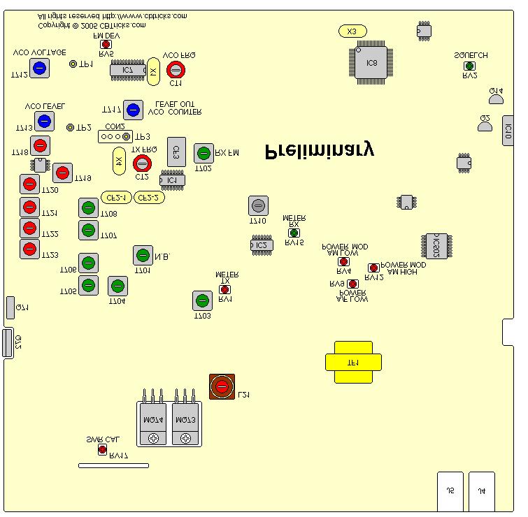
4 SET DC POWER SUPPLY VOLTAGE AT 13.8VOLT DC. WATTMETER (50 OHM) TO THE ANTENNA CONNECTOR PLL CIRCUIT ALIGNMENT PROCEDURE : (1) SET TRANSCEIVER TO FREQUENCY MHz (2) WHILE IN RECEIVER MODE, CONNECT OSCILLOSCOPE DC PROBE TO TP1 (SEE PARTS LOCATION). (3) ADJUST T712 AND OBSERVE THE DC LEVEL SWING BETWEEN 0.2 TO +7 VOLT DC. THEN SET THE DC LEVEL TO 2.8 VOLT (4) CHANGE TO BAND D, CHECK THE DC LEVEL SHOULD BE < 6V (5) WHILE IN RECEIVER MODE, CONNECT OSCILLOSCOPE DC PROBE TO TP2 (SEE PARTS LOCATION). (6) ADJUST T713 FOR MAXIMUM LEVEL (7) SET RECEIVER TO FREQUENCY MHz. CONNECT OSCILLOSCOPE PROBE TO TP4 OF CON2 AND MAXIMIZE RF LEVEL THROUGH T717. (8) WHILE IN RECEIVER MODE, CONNECT FREQUENCY COUNTER PROBE TO TP3 (SEE PARTS LOCATION). (9) SET THE FREQUENCY MHz BY MOVING TUNE SWITCH THEN ADJUST TRIMMER CT1 TO FREQUENCY MHz CARRIER OSCILLATOR PORTION PROCEDURE : (1) SET TRANSCEIVER TO FREQUENCY MHz (2) PRESS TO PTT (3) WHILE IN TRANSMIT AM/FM MODE. (4) ADJUST CT2 TO OBTAIN MHz READING.
5 RF AMP CIRCUITS ALIGNMENT PROCEDURE : 1.RX ALIGNMENT -AM (1) CONNECT THE PROVE OF RF SIGNAL MEASURING EQUIPMENT BETWEEN GROUND AND ANNTENA POINT. SET THE SINAD OF SSG TO -47dBm AND THEN ADJUST T703,704,705,706,707,708,710 FOR MAXIMUM READING ON THE EQUIPMENT. (2) AT -47 dbm SIGNAL, SQUELCH KNOB AT MAX. ALIGN THE SQUELCH CLOSE TO OPEN AT RV2 WITH HYSTERISIS OF 2-5 db. (3) AT 100 uv SQUELCH AT MINIMUM AND MODUALTION AT OFF CONDITION ALIGN RV15 FOR S-9 SPECS uv. (4) INSERT THE NB TESTER TO ANTENNA, MIN.SQUELCH, MAX. VOLUME, CONNECT OSCILLOSCOPE TEST PROBE TO COLLECTOR OF Q6 AND ADJUST T701 TO MAXIMUM READING OF EQUIPMENT. -FM (1) CHANGE TO FM BAND. SET THE SINAD OF SSG TO -47dBm AND THEN ADJUST T702 MAXIMUM READING ON THE EQUIPMENT. 2.TX ALIGNMENT (1) SET TRANSCEIVER TO FREQUENCY MHz BAND D. (2) TEST EQUIPMENT CONNECTION. AT THE BOTTOM CONNECT RF POWER METER, RF VTVM AND OSCILLOSCOPE TO ANTENNA JACK. (3) ADJUST T718,719,720,721, COILS TO OBTAIN THE MAXIMUM INDICATION ON RF VTVM (4) ADJUST L21 TO SET POWER LEVEL FROM 15 WATTS NO MODULATION. (5) WHILE IN AM TX MODE HI/LOW SWITCH TO LOW, NO MODULATION ADJUST RV9 TO OBTAIN RF CARRIER POWER OF 4W ON RF POWER METER. (6) SWITCH TO LOW POWER AND ADJUST RV4 TO OBTAIN 95% MODULATION TO ALL BANDS. (7) WHILE IN AM. TX. MODE. AF SIGNAL 30mV ADJUST RV12 TO OBTAIN 95% MODULATION. (8) ON ALL BANDS WHILE IN AM TX MODE NO MODULATION AND HI/LOW SWITCH TO HIGH ADJUST RV1 SO THAT THE METER INDICATE RF = 9 (S9) (9) WHILE IN FM. TX. MODE. AF SIGNAL 30mV ADJUST RV5 TO OBTAIN 2.5KHz DEVIATION. (10) INSERT 100 OHM DUMMY LOAD TO ANTENNA AND SWITCH TO FM LOW POWER, NO MODULATION, CALIBRATION MODE WHILE IN TX MODE, ADJUST CALIBRATION KNOB TO ATTAIN CAL LEVEL ON METER. (11) SWITCH TO SWR MODE AND ADJUST RV17 TO SET SWR =2.
6
7 A description of all circuits and devices provided for determining and stabilizing frequency: Frequency (from mhz to mhz) of transmitting, as receiving, frequencies are provided by PLL (phase locked loop) circuitry. The purpose of the PLL is to provide a multiple number of frequencies from VCO (voltage controlled oscillator) with quartz crystal accuracy and stability from one crystal oscillator reference frequency. Therefore the VCO frequency is as accurate and stable as the crystal oscillator itself. The reference crystal oscillator frequency is Mhz. And the VCO frequency mhz or local oscillators Mhz is mixer to obtain 28mhz band transmit frequency. And accurate as the mhz crystal oscillators. Therefore the TX frequencies are as stable and accurate as the mhz crystal oscillators. Stable and accurate within 18ppm over the temperature range between-30 C and 50 C, the transmitted frequencies are also stable within 25ppm over the same temperature range. DESCRIPTION OF FREQUENCY DETERMINING CIRCUIT: To eliminate frequency drift to power supply variation. A regulated supply is provided for PLL operation. The regulator consists of a regulated IC10 (8v) the Mhz crystal oscillator active part is included in the PLL IC7. See equivalent circuit block diagram of the PLL IC7. VCO AND FREQUENCY MIXER. The VCO circuit consists of following, Variator (DC voltage dependent variable capacitor) diode D30, D31 tuning coil T712. The oscillator of VCO frequency is done by a Q37 and T713. The resulting 28Mhz output frequency is filtered by T720, T721, T722, T723, Q69 is a pre-amplifier, but is also as go-no go type switch when illegal transmit frequency is generated. The logic circuit determining the illegal frequencies is located inside the PLL IC7. Q71, Q72 is a driver circuit for TX output. And Q73, Q74 is the final power amplifier the class AB type amplifier output, signal is filtered by low pass filter consisting of L230, L231, L22, L24, C305, C306, C311, C620, C621 make up a series resonant and the remaining l/c represents low pass filter. DESCRIPTION OF ANY CIRCUITS OR DEVICES EMPLOYED FOR SUPPRESSION OF : SPURIOUS RADIATION When two frequencies are mixed in non-linear devices to obtain a desired output frequency, almost unlimited number of spurious frequencies are generated at the same time. The undesired spurious frequencies are restudied from the differences and the summations of the two frequencies and their harmonics. The far-out frequencies can easily be filtered out. But the most difficult frequencies are those close to the desired output center frequency. A frequency mixer circuit used in this unit because it is far better than a mixer circuit in eliminating spurious. Also important factors contributing to spurious are poor ground path. Following steps are taken to eliminate spurious level TP will below 60db : (1) Frequency mixer circuit is employed. (2) Ground path of the printed circuit board is carefully laid out. (3) Adequate band pass filter circuits are employed to eliminate spurious at the frequency mixer output.
8 LIMITING MODULATION Since the nominal microphone (dynamic MIC) output level is about 0.6mv. The overall gain of the audio amplifier is set so that 3mv (at 1khz) will modulate RF signal to 50% then a very effective ALC (automatic level control) circuit. It is used to limit audio gain so as not to over modulate beyond 95% the dynamic range of the ALC circuit for this purpose is effective over 50 db input increase. The output audio level is sensed by Q64 and set by resistor RV12. A positive going signal will trigger open the Q43, Q44. LOW POWER When all the coils are adjusted for peak, the RF power output shall not exceed 4.4 watts at low power mode. SUPPRESSION OF HARMONICS RADIATION The class AB type amplifier output signal is filtered by low pass filter consisting of L230, L231, L22, L24, C305, C306, C311, C620, C621 make up a series resonant circuit and the remaining l/c represents low pass filter. The harmonics radiation are suppressed by these filter circuits sufficiently and reduced to below 60db.
200GTL ALIGNMENT REVISION: 1.0 BURKE MODEL: 200GTL REVISION: 1.2 DATE: 02/14/06. Total Pages: 6 pages. Page:1 print date: 9/23/09
 ALIGNMENT PROCEDURE MODEL: 200GTL REVISION: 1.2 DATE: 02/14/06 PREPARED BY: BURKE Total Pages: 6 pages Page:1 print date: 9/23/09 1 TEST CONDITION: 200GTL ALIGNMENT INSTRUCTION 1.0. TEST TEMPERTAURE: 77
Galaxy DX949, 959, 2547 ERF-2030 Mod Package This Mod Package is provided by
 This Mod Package is provided by CBTricks.com Someone who wanted to help you repair your equipment put together this information. Galaxy DX949, 959, 2547 ERF-2030 Mod Package This mod will also work on
BLOCK DIAGRAM - I J Li) N 6. w IS) AF D RIVE R R F D RIVE R R F P OWE R AMP PL L OSC UNIT. LL co X X X Lti X. C X W N O C..) 4 C.
 N 6. w IS) AF D RIVE R R F D RIVE R R F P OWE R AMP PL L OSC UNIT. LL co X X X Lti X. C X W N O C..) 4 C.") MODEL 1-632 BLOCK DIAGRAM tl LL co a. LL O ox X X X X < X C.) W N C U) LL CO aa 1.11 t O - I J Ul Li) Lti N w IS) 1 X. C X Ir t AF D RIVE R X - LL C.) CD r.--1111 MOP U) N N 6 PL L OSC UNIT R F D RIVE
MODEL 1-632 BLOCK DIAGRAM tl LL co a. LL O ox X X X X < X C.) W N C U) LL CO aa 1.11 t O - I J Ul Li) Lti N w IS) 1 X. C X Ir t AF D RIVE R X - LL C.) CD r.--1111 MOP U) N N 6 PL L OSC UNIT R F D RIVE
FT-897 Alignment. Local Oscillator Adjustment. PLL Adjustment
 FT-897 Local Oscillator Adjustment Reference Frequency Adjustment a. Connect a frequency counter to TP1032. b. Adjust the trimmer capacitor (TC5001) for 67.875000MHz ±5Hz on the frequency counter. c. Connect
ALAN 48P 4W SMT MULTI CIRCUIT DESCRIPTION
 ALAN 48P 4W SMT MULTI CIRCUIT DESCRIPTION INTRODUCTION 1.Multi BAND:Italy,Italy-34CH, Germany-80CH, Germany,Germany-80CH-40CH-4W Spain, Europe, CEPT, England, England-CEPT, Poland,Poland-400CH, Russi a-400ch,france,sweden
Frequency Coverage MHz RF Power Output 30W SSB / 9W AM/ 30W FM Dual Finals on Heat Sink Modes AM, FM, USB, LSB Microprocessor
 MAGNUM M-257 30W AM/ /FM/SSB 10--11 Meterr Mobile Trranscei ivverr n Prri iiccee: : US$ 250..00 eexx ssttoocckk JJaakkaarrttaa (Arrrri ( iivvi iinngg 2 d weeeekk iinn i Maarrcchh) ) SPECIFICATIONS Frequency
THEORY OF OPERATION. TM308EUL for Cobra Nov 06,2006
 THEORY OF OPERATION TM308EUL for Cobra Nov 06,2006 This PLL controlled VHF marine mobile transceiver provides an accurate and stable multi-channel operation. The transceiver consists of 15 main sections
MAINTENANCE MANUAL TRANSMITTER/RECEIVER BOARD CMN-234A/B FOR MLSU141 & MLSU241 UHF MOBILE RADIO TABLE OF CONTENTS
 MAINTENANCE MANUAL TRANSMITTER/RECEIVER BOARD CMN-234A/B FOR MLSU141 & MLSU241 UHF MOBILE RADIO TABLE OF CONTENTS DESCRIPTION... 2 CIRCUIT ANALYSIS... 2 TRANSMITTER... 2 9-Voft Regulator... 2 Exciter...
LBI-30398N. MAINTENANCE MANUAL MHz PHASE LOCK LOOP EXCITER 19D423249G1 & G2 DESCRIPTION TABLE OF CONTENTS. Page. DESCRIPTION...
 MAINTENANCE MANUAL 138-174 MHz PHASE LOCK LOOP EXCITER 19D423249G1 & G2 LBI-30398N TABLE OF CONTENTS DESCRIPTION...Front Cover CIRCUIT ANALYSIS... 1 MODIFICATION INSTRUCTIONS... 4 PARTS LIST AND PRODUCTION
IC-400pro - RADIOAFICION.COM
 PROCEDURES IC-400pro - 5- PREPARATION When you adjust the contents on pages 5-5 and 5-6, SOFT- WARE, the optional CS-400PRO ADJ SOFTWARE (Rev..0 or later), *OPC- JIG CABLE (modified OPC- CLONING CABLE;
ERICSSONZ LBI-30398P. MAINTENANCE MANUAL MHz PHASE LOCKED LOOP EXCITER 19D423249G1 & G2 DESCRIPTION TABLE OF CONTENTS
 MAINTENANCE MANUAL 138-174 MHz PHASE LOCKED LOOP EXCITER 19D423249G1 & G2 TABLE OF CONTENTS Page DESCRIPTION... Front Cover CIRCUIT ANALYSIS...1 MODIFICATION INSTRUCTIONS...4 PARTS LIST...5 PRODUCTION
Yaesu FT-8800R Alignment
 DUAL BAND FM TRANSCEIVER Introduction and Precautions The FT-8800R has been carefully aligned at the factory for the specified performance across the 144 MHz and 430 MHz amateur bands. Realignment should
This Information Is Provided By
 This Information Is Provided By CBTricks.com How to update the Galaxy Radios For using IRF520 MOSFET s. Dual final AM/FM/SSB Chassis Only Liability of damages to any equipment is the sole responsibility
TS-590S ADJUSTMENT. Updating the Firmware. Required Test Equipment. Preparation
 Updating the Firmware The firmware of the main MCU and DSP can be updated using the TS590 Update update software. Update the firmware according to the procedure displayed in update software. Refer to the
Cubic Astro 103 Restoration Notes
 Cubic Astro 103 Restoration Notes W7CPA February 2016 I restored a Cubic Astro 103 a few years ago and have enjoyed operating it for years. It s a very nice geezer wireless and the last amateur radio product
MAINTENANCE MANUAL RF BOARD 19D901835G1 ( MHz) 19D901835G2 ( MHz) FOR MVS
 19D901835G2 ( MHz) FOR MVS") D MAINTENANCE MANUAL F BOAD 19D901835G1 (136-153 MHz) 19D901835G2 (150-174 MHz) FO MVS TABLE OF CONTENTS DESCIPTION............................................... Front Cover CICUIT ANALYSIS..............................................
D MAINTENANCE MANUAL F BOAD 19D901835G1 (136-153 MHz) 19D901835G2 (150-174 MHz) FO MVS TABLE OF CONTENTS DESCIPTION............................................... Front Cover CICUIT ANALYSIS..............................................
Maintenance Manual TRANSMITTER/RECEIVER BOARD CMN-233 FOR MLSH041
 Maintenance Manual TRANSMITTER/RECEIVER BOARD CMN-233 FOR MLSH041 TABLE OF CONTENTS Page DESCRIPTION... 2 CIRCUIT ANALYSIS... 2 Transmitter... 2 9-volt Regulator... 2 Exciter... 2 40-Watt PA... 2 Antenna
18-CHANNEL MOBILE CB TRANSCEIVER MODEL CB-845
 18-CHANNEL MOBILE CB TRANSCEIVER MODEL CB-845 INSTRUCTION HANDBOOK RAll JEFFERSOn CITIZEN BAND RADIO MESSAGE TO THE OWNER CONGRATULATIONS! As the new owner of Ray Jefferson Model CB-845 CB Mobile Transceiver,
KWM-2/2A Transceiver THE COLLINS KWM-2/2A TRANSCEIVER
 KWM-2/2A Transceiver Click the photo to see a larger photo Click "Back" button on browser to return Courtesy of Norm - WA3KEY THE COLLINS KWM-2/2A TRANSCEIVER Unmatched for versatility, dependability and
OPERATOR S MANUAL KYODO WEST MODEL KG506 FULL-DUPLEX MOBILE. Preliminary
 OPERATOR S MANUAL KYODO WEST MODEL KG506 FULL-DUPLEX MOBILE Preliminary 1.0 INTRODUCTION Thank you for purchasing the KYODO WEST MODEL KG506 Full-Duplex Mobile Radio. This manual contains information to
Adjustment for IC-910H. Adjustment. Adjustment
 for IC-910H 30.2 MHz Level 430MHz 2 nd Lo (60.4MHz) Peak Setting the 60.4MHz Frequency the144mhz 1 st Lo Lock Voltage th430mhz 1 st Lo Lock Voltage 144MHz RX Peak/ Gain Band Peak Band Total Gain Sub- Band
DX AM FM SSB CW PA Amateur Base Station Transceiver OWNER S MANUAL RX / TX 2 4 POWER NF CHANNEL MODE RF POWER OFF CAL OFF OFF CALIBRATE
 1 2 3 6 4050 ULA 6070 TI 80 90 100 9 DX 2517 2517 RX / TX 0 2 4 SWR WATTS SET 81012 22 1 010 3 2030 5 MOD 7 ON dbover 9 SIGNAL +20 +40+60 PA FM AM USB LSB CW POWER ON SWR NB / ANL R.BEEP +10KHz NF CHANNEL
ACCESSORY CIRCUITS ALIGNMENT
 UNIDEN 22 ACCESSOY CICUITS ALIGNMENT 1. NOISE BLANKE Adjustment 11. Test Equipment equired (1) DC Voltage Meter 12. Adjustment Procedures. (1) Set MODE SWITCH to USB, and recive 14.2 Mhz. (2) Activate
Construction Manual 4m-Linear-Transverter XV4-15
 Construction Manual 4m-Linear-Transverter XV4-15 Holger Eckardt DF2FQ Kirchstockacherstr. 33 D-85662 Hohenbrunn 3207 Technical data exciter frequency: 21.0... 21.5 MHz RF frequency: 70.0.. 70.5 MHz supply
hallicrafters PERFORMANCE SPECIFICATIONS MODEL: SR-2000 LATEST REVISION: 18 JAN 66 Code ident # Specification #
 hallicrafters PERFORMANCE SPECIFICATIONS MODEL: SR-2000 LATEST REVISION: 18 JAN 66 Code ident # 26916 Specification # 093-002154 I. GENERAL A. Power input 117V 50-60 cycles from a source capable of delivering
Operation Manual. SlJPER ST AR Channel Mobile 5-Mode Transceiver -----~- --:.. KTSS200NXX ,, I
 Operation Manual!.,, SlJPER ST AR 2000 200 Channel Mobile 5-Mode Transceiver -----~- --:.. KTSS200NXX General Description l Frequency/Channel Chart The Super Star -2000 is a combination transmitter-receiver
ICOM IC-201 Allmode Transceiver
 ICOM IC-201 Allmode Transceiver Alignment Procedure Please note: This procedure is reengineered by myself and may be not in accordance with the original procedure from the manufacturer! So I can t accept
Receiver Adjustments
 ! -8-4!5 This Section details procedures for tuning and adjustment of T2000 series II radios. This is normally only required during product manufacture or after major servicing. The following topics are
SERVICE MANUAL. TECtalk 2-WAY PORTABLE HANDHELD PMR RADIO. Jan. 2000
 1 SERVICE MANUAL 2-WAY PORTABLE HANDHELD PMR RADIO TECtalk Jan. 2000 2 CONTENTS 1. GENERAL 1.1 General 1.2 Characteristics and features 2. SPECIFICATION 2.1 General Specification 2.2 Electrical Specification
Construction Manual 6m-Linear-Transverter XV6/10
 Construction Manual 6m-Linear-Transverter XV6/10 Holger Eckardt DF2FQ Kirchstockacherstr. 33 D-85662 Hohenbrunn 2606 Technical data exciter frequency: 28... 30 MHz RF frequency: 50... 52 MHz supply voltage:
Maintenance Manual. MTD SERIES 900 MHz, 10-WATT, DATA ONLY MOBILE RADIO. Mobile Communications LBI TABLE OF CONTENTS
 Mobile Communications MTD SERIES 900 MHz, 10-WATT, DATA ONLY MOBILE RADIO TABLE OF CONTENTS RF BOARD............................... LBI-38545 AUDIO BOARD............................ LBI-38546 LOGIC BOARD............................
CON NEX HP. OWNER'S MANUAL Full Channel AM/FM Amateur Mobile Transceiver TABLE OF CONTENTS TUNING THE ANTENNA FOR OPTIMUM S.W.R..
 TABLE OF CONTENTS PAGE SPECIFICATIONS... 2 INSTALLATION... 3 LOCATION... 3 CON NEX - 4300HP MOUNTING THE RADIO... 3 IGNITION NOISE INTERFERENCE... 4 ANTENNA... 4 TUNING THE ANTENNA FOR OPTIMUM S.W.R..
DX 33HP. 10 Meter Amateur Mobile Transceiver OWNER S MANUAL. Download this Manual Free of Charge at
 DX 33HP SIG 1 3 TX PWR 5 7 9+30dB POWER HI NB/ANL MED LO HI LO BAND ECHO RX/TX VOL SQ MIC RF FM PA AM D/A E/B F/C ECHO TIME BAND 10 Meter Amateur Mobile Transceiver Download this Manual Free of Charge
MODEL AF200A: FM, FM/SCA RECEIVER/MONITOR OPERATION MANUAL
 MODEL AF200A: FM, FM/SCA RECEIVER/MONITOR OPERATION MANUAL THE AF200A IS AN FM AND FM/SCA PROFESSIONAL STYLE RECEIVER/ MONITOR. IT S MANY APPLICATIONS INCLUDE STATION MONITORING AND EAS MONITORING. The
MASTR II BASE STATION MHz RECEIVER IF/AUDIO/SQUELCH & RF ASSEMBLY (25 khz/12.5 khz CHANNEL SPACING) Maintenance Manual LBI-38506A
 Maintenance Manual LBI-38506A") A Mobile Communications MASTR II BASE STATION 806-824 MHz RECEIVER IF/AUDIO/SQUELCH & RF ASSEMBLY (25 khz/12.5 khz CHANNEL SPACING) TABLE OF CONTENTS RF ASSEMBLY, MIXER AND IF FILTER BOARD...... LBI-30482
A Mobile Communications MASTR II BASE STATION 806-824 MHz RECEIVER IF/AUDIO/SQUELCH & RF ASSEMBLY (25 khz/12.5 khz CHANNEL SPACING) TABLE OF CONTENTS RF ASSEMBLY, MIXER AND IF FILTER BOARD...... LBI-30482
RCI-6300F25/150. Owner's Manual. AM/FM Amateur Transceiver With Built-in Frequency Counter. Table of Contents. Downloaded from
 Table of Contents RCI-6300F25/150 AM/FM Amateur Transceiver With Built-in Frequency Counter PAGE Chapter 1 Specifications...... 2 Chapter 2 Installation...... 3 Installing the Radio... 3 Ignition Noise
Installation... 3 Installing The Radio... 3 Ignition Noise Interference... 4 Antenna... 4 External Speaker... 4 Public Address...
 TABLE OF CONTENTS CHAPTER 1 Specifications.............................................. 2 PAGE BIG RIG SERIES S 1 MOD PW R 20 0 3 SW R 40 1 5 5 60 1.5 7 10 2 9 20 80 3 30 +20 40 50 +40 100% MAX db +60
MAINTENANCE MANUAL FOR MHz PERSONAL TWO-WAY FM RADIO COMBINATION
 MAINTENANCE MANUAL FOR 896-941 MHz PERSONAL TWO-WAY FM RADIO COMBINATION TABLE OF CONTENTS Page INTRODUCTION................................................... 1 PHASE 1: RADIO SECTION TROUBLSHOOTING Functional
KACHINA 1 SSB TRANSCEIVER
 KACHINA 1 SSB TRANSCEIVER THEORY OF OPERATION The Kachina 1 Amateur Band Transceiver is a highly sophisticated, state of the art, piece of communication equipment, housed in the smallest of packages. Yet,
FCC ID: AXI IC: 10239A Alignment
 Introduction The VX-261 is carefully aligned at the factory for the specified performance across the frequency range specified for each version. Realignment should therefore not be necessary except in
HAMTRONICS TB901 FM EXCITER INSTALLATION, OPERATION, & MAINTENANCE
 HAMTRONICS TB901 FM EXCITER INSTALLATION, OPERATION, & MAINTENANCE GENERAL INFORMATION. The TB901 is a single-channel low power fm transmitter (exciter) designed to provide 300-600 milliwatts continuous
ERICSSONZ LBI-39123A. MAINTENANCE MANUAL FOR 21.4 MHz RECEIVER IF MODULE 12.5/25 khz CHANNEL SPACING 19D902783G7 DESCRIPTION TABLE OF CONTENTS
 A MAINTENANCE MANUAL FOR 21.4 MHz 12.5/25 khz CHANNEL SPACING 19D902783G7 TABLE OF CONTENTS Page DESCRIPTION............................................ Front Cover GENERAL SPECIFICATIONS....................................
The Uniden Grant XL Owners Site
 The Uniden Grant XL Owners Site Modifications page for the Grant XL (For Informational purposes only) The author of this site takes NO responsibility for illegal modifications and/or use of illegally modified
MAINTENANCE MANUAL RF BOARD 19D902243G4 ( MHz) 19D902243G5 ( MHz) 19D902243G6 ( MHz) FOR MVS
 19D902243G5 ( MHz) 19D902243G6 ( MHz) FOR MVS") LI-38258D IC DATA MAINTENANCE MANUAL F OAD 19D902243G4 (403-440 MHz) 19D902243G5 (440-470 MHz) 19D902243G6 (470-512 MHz) FO MVS OPEATIONAL AMPLIFIE 19A701789P2 QUAD ILATEAL SWITCH (U202) 19A700029P44 TALE
LI-38258D IC DATA MAINTENANCE MANUAL F OAD 19D902243G4 (403-440 MHz) 19D902243G5 (440-470 MHz) 19D902243G6 (470-512 MHz) FO MVS OPEATIONAL AMPLIFIE 19A701789P2 QUAD ILATEAL SWITCH (U202) 19A700029P44 TALE
CX7 Troubleshooting Index
 CX7 Troubleshooting Index Modification S/1 Newsletter Guide Board Description A/TO A/TO MODE Intermod V1,12 P4.4 A11 Shut off one 35 MHz osc in receive, done sn 244 A/TO Spur V1,12 P1 Reduce A/TO spur,
AC LAB ECE-D ecestudy.wordpress.com
 PART B EXPERIMENT NO: 1 AIM: PULSE AMPLITUDE MODULATION (PAM) & DEMODULATION DATE: To study Pulse Amplitude modulation and demodulation process with relevant waveforms. APPARATUS: 1. Pulse amplitude modulation
LBI-31564A. Mobile Communications. DELTA - SX MHz RADIO COMBINATIONS (NEGATIVE GROUND ONLY) Maintenance Manual
 Maintenance Manual") A Mobile Communications DELTA - SX 136-174 MHz RADIO COMBINATIONS (NEGATIVE GROUND ONLY) Maintenance Manual TABLE OF CONTENTS MILITARY AND SYSTEM SPECIFICATIONS................................. 2-3 COMBINATION
A Mobile Communications DELTA - SX 136-174 MHz RADIO COMBINATIONS (NEGATIVE GROUND ONLY) Maintenance Manual TABLE OF CONTENTS MILITARY AND SYSTEM SPECIFICATIONS................................. 2-3 COMBINATION
AVL-10000T AUDIO VIDEO LINK TRANSMITTER TECHNICAL MANUAL
 AVL-10000T AUDIO VIDEO LINK TRANSMITTER TECHNICAL MANUAL Document : AVL-10000T Version: 1.00 Author: Henry S Date: 25 July 2008 This module contains protection circuitry to guard against damage due to
DX 33HML. Full Channel AM/FM Mobile Transceiver OWNER S MANUAL. Printed In Malaysia AT H PD000802
 DX 33HML Full Channel AM/FM Mobile Transceiver Printed In Malaysia AT3601014H PD000802 OWNER S MANUAL TABLE OF CONTENTS Page Specification.................................... 2 Installation Location.....................................
Maintenance Manual. ORION UHF (Dual Bandwidth) SCAN AND SYSTEM MOBILE RADIO. ericssonz LBI TABLE OF CONTENTS
 SCAN AND SYSTEM MOBILE RADIO. ericssonz LBI TABLE OF CONTENTS") Maintenance Manual ORION UHF (Dual Bandwidth) SCAN AND SYSTEM MOBILE RADIO TABLE OF CONTENTS Synthesizer/Receiver/Exciter....... LBI-39163 Power Amplifier.............. LBI-39164 PA Interface................
Maintenance Manual ORION UHF (Dual Bandwidth) SCAN AND SYSTEM MOBILE RADIO TABLE OF CONTENTS Synthesizer/Receiver/Exciter....... LBI-39163 Power Amplifier.............. LBI-39164 PA Interface................
Exercise 2: FM Detection With a PLL
 Phase-Locked Loop Analog Communications Exercise 2: FM Detection With a PLL EXERCISE OBJECTIVE When you have completed this exercise, you will be able to explain how the phase detector s input frequencies
E-200D ALIGNMENT. See the end of the procedure for the location of the calibration points. EQUIPMENT REQUIRED
 E-200D ALIGNMENT NOTE: This is not an official B&K alignment procedure. This procedure was created by experimenting with an E-200D. However when this procedure is followed, the resulting calibration should
Module 8 Theory. dbs AM Detector Ring Modulator Receiver Chain. Functional Blocks Parameters. IRTS Region 4
 Module 8 Theory dbs AM Detector Ring Modulator Receiver Chain Functional Blocks Parameters Decibel (db) The term db or decibel is a relative unit of measurement used frequently in electronic communications
3 T856/857 Initial Tuning & Adjustment
 M850-00 T856/857 Initial Tuning & Adjustment C3.1 3 T856/857 Initial Tuning & Adjustment The following section describes the full tuning and adjustment procedure and provides information on: channel programming
OWNER'S MANUAL Channels All-Mode AM/FM/USB/LSB Built in Frequency Counter Mobile Transceiver with Roger Beep
 SUPER STAR 7QOODX OWNER'S MANUAL 3360 Channels All-Mode AM/FM/USB/LSB Built in Frequency Counter Mobile Transceiver with Roger Beep TABLE OF CONTENTS Page Specifications... 2 Installation Location... 4
ericssonz LBI-38640E MAINTENANCE MANUAL FOR VHF TRANSMITTER SYNTHESIZER MODULE 19D902780G1 DESCRIPTION
 MAINTENANCE MANUAL FOR VHF TRANSMITTER SYNTHESIZER MODULE 19D902780G1 TABLE OF CONTENTS Page DESCRIPTION........................................... Front Cover GENERAL SPECIFICATIONS...................................
AM/FM 10 METER MOBILE AMATEUR TRANSCEIVER OPERATING MANUAL
 AM/FM 10 METER MOBILE AMATEUR TRANSCEIVER OPERATING MANUAL INTRODUCTION Congratulations on your purchase of a Magnum S-6 AM/FM 10 meter transceiver. Your Magnum S-6 is designed to provide years of enjoyment
ALAN HP 106 SERVICE MANUAL
 ALAN HP 106 SERVICE MANUAL HP106 Service Manual ALAN HP106 Portable VHF Transceiver Service Manual Copyright 2003 by CTE International Italy; all rights reserved Page 1 of 12 HP106 Service Manual Contents
DX 66V OWNER S MANUAL. Full Channel AM/FM Mobile Transceiver Built in Frequency Counter with Roger Beep
 WARRANTY This radio is covered by a two year limited parts and labor warranty. Limited means that we will repair problems caused by factory defects or normal use at no charge. Before returning a radio
Second Hand Yaesu FTDX5000MP HF base station transceiver
 263 Walsall Road, Great Wyrley, Walsall, WS6 6DL Established 1997. Open Monday - Friday 9am - 5pm and Saturday 9.30am - 4pm Tel: 01922 414 796 Fax: 01922 417829 Skype: radioworld_uk Second Hand Yaesu FTDX5000MP
: Hacking Bitx Version3B, C: : 20mt to 40mt band: PART I
 : Hacking Bitx Version3B, C: : 20mt to 40mt band: PART I Fig 1: Bitx Ver3C SBL-1 20 Conversion for Bitx40 The picture in Fig1 is a Bitx3C SBL-1 for 40mt band, constructed from the Bitx Version 3C SBL-1
ERICSSONZ LBI-39123C. MAINTENANCE MANUAL FOR 21.4 MHz RECEIVER IF MODULE 12.5/25 khz CHANNEL SPACING 19D902783G7 & G11 DESCRIPTION TABLE OF CONTENTS
 MAINTENANCE MANUAL FOR 21.4 MHz 12.5/25 khz CHANNEL SPACING 19D902783G7 & G11 TABLE OF CONTENTS Page DESCRIPTION............................................ Front Cover GENERAL SPECIFICATIONS....................................
Boonton 202E set to 200 mc, frequency modulated by HP 200 CD AUDIO oscillator, feeding a 10 u-v signal to the HI band receiver
 SRR-5 System Test Procedure w X J»"«". Tgra^^i nnnrww ini in m 1.0 HEADSET AUDIO Receiver Control Settings; Band: HI, set to 200 mc Function: FM Boonton 202E set to 200 mc, frequency modulated by HP 200
12kHz LIF Converter V2.43 9Mhz version
 12kHz LIF Converter V2.43 9Mhz version Please Note: This document supersedes all previously released documents and drawings on the LIF subject. This is the latest and most up-to-date document at this time.
ERICSSONZ LBI-39123D. MAINTENANCE MANUAL FOR 21.4 MHz RECEIVER IF MODULE 12.5/25 khz CHANNEL SPACING 19D902783G7 & G11 DESCRIPTION
 MAINTENANCE MANUAL FOR 21.4 MHz RECEIVER IF MODULE 12.5/25 khz CHANNEL SPACING 19D902783G7 & G11 TABLE OF CONTENTS Page DESCRIPTION............................................ Front Cover GENERAL SPECIFICATIONS....................................
WIRELESS MICROPHONE. Audio in the ISM band
 WIRELESS MICROPHONE udio in the ISM band Ton Giesberts When the ISM frequency band was made available in Europe for audio applications, Circuit Design, a manufacturer of professional RF modules, decided
2m Weak Signal Sources January 2018
 2m Weak Signal Sources January 2018 Rick Campbell This white paper describes a set of signal sources at power levels from -30dBm to +12dBm in the 144 MHz amateur radio band. All are legal for direct connection
INSTRUCTION MANUAL MODEL 2779 SUBCARRIER MODULATOR
 INSTRUCTION MANUAL MODEL 2779 SUBCARRIER MODULATOR Data, drawings, and other material contained herein are proprietary to Cross Technologies, Inc., and may not be reproduced or duplicated in any form without
MODERN AM BROADCAST STATIONS AM STEREO CQUAM WITH DDS
 MODERN AM BROADCAST STATIONS AM STEREO CQUAM WITH DDS DDS EXCITER OPERATING MANUAL 20W CARRIER - 80W PEP WHAT IS DDS? IT IS THE INITIALS OF THE WORDS DIRECT DIGITAL SYNTHESIZER. THAT MEANS: DIRECT DIGITAL
SPECIFICATIONS: Subcarrier Frequency 5.5MHz adjustable, FM Modulated +/- 50KHz. 2nd 11MHz >40dB down from 5.5MHz
 Mini-kits AUDIO / SUBCARRIER KIT EME75 Version4 SPECIFICATIONS: Subcarrier Frequency 5.5MHz adjustable, FM Modulated +/- 50KHz Subcarrier Output 1.5v p-p Output @ 5.5MHz DESCRIPTION & FEATURES: The Notes
HF Receivers, Part 3
 HF Receivers, Part 3 Introduction to frequency synthesis; ancillary receiver functions Adam Farson VA7OJ View an excellent tutorial on receivers Another link to receiver principles NSARC HF Operators HF
BK2 Series. STE KSOLUTIONS BK2x DATA SHEET. TABLE 1 PERFORMANCE DATA BK2x RECEIVER SECTION 80 to 650 MHz / 842 to 916 MHz¹ 2FSK GFSK RCFSK 3FSK 4FSK
 BKx BK Series Module Dimensions 33 mm x 5 mm The BKxx series of modules offers a wide choice of frequency band selection: 69 MHz, 35 or 434 MHz, 868 or 95 MHz. The modules are NBFM (Narrow Band Frequency
THE AMAZING BARLOW WADLEY XCR-30 CRYSTAL CONTROLLED 30 BAND TRANSISTOR RADIO. (A method to set the AGC) H. Holden, 2018.
 H. Holden, 2018.") THE AMAZING BARLOW WADLEY XCR-30 CRYSTAL CONTROLLED 30 BAND TRANSISTOR RADIO. (A method to set the AGC) H. Holden, 2018. Introduction: The Barlow Wadley XCR-30 radio is well known to amateur radio enthusiasts
THE AMAZING BARLOW WADLEY XCR-30 CRYSTAL CONTROLLED 30 BAND TRANSISTOR RADIO. (A method to set the AGC) H. Holden, 2018. Introduction: The Barlow Wadley XCR-30 radio is well known to amateur radio enthusiasts
DX 29HP. 10 Meter Amateur Mobile Transceiver OWNER S MANUAL PRINTED IN MALAYSIA PN:A412308CNA
 DX 29HP 10 Meter Amateur Mobile Transceiver OWNER S MANUAL PRINTED IN MALAYSIA PN:A412308CNA TABLE OF CONTENTS Page Specification.................................... 2 Installation Location.....................................
ERICSSONZ LBI MAINTENANCE MANUAL ORION MHz (Dual Bandwidth) SYNTHESIZER/RECEIVER/EXCITER BOARD B19/CMN-352 DA/DB DESCRIPTION
 SYNTHESIZER/RECEIVER/EXCITER BOARD B19/CMN-352 DA/DB DESCRIPTION") MAINTENANCE MANUAL ORION 136-174 MHz (Dual Bwidth) SYNTHESIZER/RECEIVER/EXCITER BOARD B19/CMN-352 DA/DB TABLE OF CONTENTS Page DESCRIPTION............................................ Front. Cover CIRCUIT
MAINTENANCE MANUAL ORION 136-174 MHz (Dual Bwidth) SYNTHESIZER/RECEIVER/EXCITER BOARD B19/CMN-352 DA/DB TABLE OF CONTENTS Page DESCRIPTION............................................ Front. Cover CIRCUIT
DEM Part Number L144-28INTCK 144 MHz Transverter Kit and complete kit
 DEM Part Number L144-28INTCK 144 MHz Transverter Kit and complete kit Power Out: Noise Figure and Gain: DC Power Requirement: 50 mw linear minimum 3.5 db NF nominal, 5 dbg maximum 12-15.5 VDC, 13.8 nominal
FREQUENCY AGILE FM MODULATOR INSTRUCTION BOOK IB
 FMT615C FREQUENCY AGILE FM MODULATOR INSTRUCTION BOOK IB1215-02 TABLE OF CONTENTS SECTION SUBJECT 1.0 Introduction 2.0 Installation & Operating Instructions 3.0 Specification 4.0 Functional Description
WARNING WELCOME TO USE RESET
 WARNING Please install the antenna (connect to the location B on the back panel of the radio) and set the SWR (Standing Wave Ratio) before transmitting. Failure to do so may result in destruction of the
Beta-test ED1 PCB installed in I0CG s K1
 K1 SSB Modification (Ed.2) This description provides the receiver (RX) modifications, assembly, alignment and operation as a first step. In a second step you can add the remaining transmitter (TX) modifications,
MAINTENANCE MANUAL UHF REAR COVER ASSEMBLY 19C337097G4 - G7, G11, G13
 LBI-38383D SCHEMATIC DIAGRAM MAINTENANCE MANUAL UHF REAR COVER ASSEMBLY 19C337097G4 - G7, G11, G13 TABLE OF CONTENTS Page DESCRIPTION........................................... Front Cover CIRCUIT ANALYSIS........................................
DX 73V OWNER S MANUAL FULL FEATURED AM/FM MOBILE TRANSCEIVER. WARRANTY This radio is covered by a two year limited parts and labor warranty.
 WARRANTY This radio is covered by a two year limited parts and labor warranty. Limited means that we will repair problems caused by factory defects or normal use at no charge. Before returning a radio
Receiver Design. Prof. Tzong-Lin Wu EMC Laboratory Department of Electrical Engineering National Taiwan University 2011/2/21
 Receiver Design Prof. Tzong-Lin Wu EMC Laboratory Department of Electrical Engineering National Taiwan University 2011/2/21 MW & RF Design / Prof. T. -L. Wu 1 The receiver mush be very sensitive to -110dBm
GRAND STRAND AMATEUR RADIO CLUB
 The GRAND STRAND AMATEUR RADIO CLUB (GSARC) Myrtle Beach SC is offering used amateur related equipment for sale. Written bids may be submitted to the GSARC up to Friday, November 23 rd, 2018. Only currently
A NEW LIFE FOR THE FT-290R TRANSCEIVER! By F5RCT
 A NEW LIFE FOR THE FT-290R TRANSCEIVER! By F5RCT The FT290R is an old amateur radio workhorse which was a very popular transceiver during the 80 s. It is a 2metre multimode portable which can run with
From German Radio Amateur Jochen Heilemann (DG2IAQ) Dragon SS-201 Version MHz AM/FM/SSB Handheld Transceiver, 4-6 Watts
 Dragon SS-201 Version MHz AM/FM/SSB Handheld Transceiver, 4-6 Watts") Introduction The beautiful handheld transceiver came with a very quiet and low modulation. The original FM deviation was only 1,5 khz on mine! With the FM deviation pot on maximum! Normally you should
Introduction The beautiful handheld transceiver came with a very quiet and low modulation. The original FM deviation was only 1,5 khz on mine! With the FM deviation pot on maximum! Normally you should
Technician Licensing Class. Lesson 4. presented by the Arlington Radio Public Service Club Arlington County, Virginia
 Technician Licensing Class Lesson 4 presented by the Arlington Radio Public Service Club Arlington County, Virginia 1 Quiz Sub elements T6 & T7 2 Good Engineering Practice Sub element T8 3 A Basic Station
Applications Note RF Transmitter and Antenna Design Hints
 This application note covers the TH7107,TH71071,TH71072,TH7108,TH71081,TH72011,TH72031,TH7204 Single Frequency Transmitters. These transmitters have different features and cover different bands but they
MODEL FS-4 INSTRUCTION MANUAL R.L. DRAKE COMPANY, MIAMISBURG, OHIO, U.S.A.
 MODEL FS-4 F R E Q U E N C Y S Y N T H E S I Z E R INSTRUCTION MANUAL R.L. DRAKE COMPANY, MIAMISBURG, OHIO, U.S.A. LIMITED WARRANTY R. L. DRAKE COMPANY warrants to the original purchaser that this product
SUPERSTAR TABLE OF CONTENTS AM/FM/USB/LSB/CW AMATEUR MOBILE TRANSCEIVER WITH BUILT-IN FREQUENCY COUNTER OWNER S MANUAL
 SUPERSTAR TABLE OF CONTENTS AM/FM/USB/LSB/CW AMATEUR MOBILE TRANSCEIVER WITH BUILT-IN FREQUENCY COUNTER PAGE CHAPTER 1 Specifications............................................... 2 CHAPTER 2 Installation.................................................
4/30/2012. General Class Element 3 Course Presentation. Practical Circuits. Practical Circuits. Subelement G7. 2 Exam Questions, 2 Groups
 General Class Element 3 Course Presentation ti ELEMENT 3 SUB ELEMENTS General Licensing Class Subelement G7 2 Exam Questions, 2 Groups G1 Commission s Rules G2 Operating Procedures G3 Radio Wave Propagation
unit: mm 3196-DIP30SD
 Ordering number : EN4787A Monolithic Linear IC LA1836, 1836M Single-Chip Home Stereo Electronic Tuning IC Overview AM: RF amplifier, mixer, oscillator (with ALC), IF amplifier, detector, AGC, oscillator
List of Figures. Sr. no.
 List of Figures Sr. no. Topic No. Topic 1 1.3.1 Angle Modulation Graphs 11 2 2.1 Resistor 13 3 3.1 Block Diagram of The FM Transmitter 15 4 4.2 Basic Diagram of FM Transmitter 17 5 4.3 Circuit Diagram
LA1845NV. Monolithic Linear IC Single-Chip Home Stereo IC
 Ordering number : ENN*7931 LA1845NV Monolithic Linear IC Single-Chip Home Stereo IC The LA1845NV is designed for use in mini systems and is a single-chip tuner IC that provides electronic tuning functions
Exercise 1: RF Stage, Mixer, and IF Filter
 SSB Reception Analog Communications Exercise 1: RF Stage, Mixer, and IF Filter EXERCISE OBJECTIVE DISCUSSION On the circuit board, you will set up the SSB transmitter to transmit a 1000 khz SSB signal
Mastr III P25 Base Station Transmitter Tune-up Procedure
 Mastr III P25 Base Station Transmitter Tune-up Procedure 1. Overview The Mastr III Base Station transmitter alignment is performed in several steps. First, the Transmit Synthesizer module is aligned to
RF/IF Terminology and Specs
 RF/IF Terminology and Specs Contributors: Brad Brannon John Greichen Leo McHugh Eamon Nash Eberhard Brunner 1 Terminology LNA - Low-Noise Amplifier. A specialized amplifier to boost the very small received
LnR Precision, Inc. 107 East Central Avenue, Asheboro, NC
 LD5 CW/SSB QRP Transceiver Quick guide manual Description: At the development base of the digital signal processing unit, an algorithm is embedded for IQ processing of the channels with phase suppression
FMC664CC FM BAND CONVERTER
 FMC664CC FM BAND CONVERTER INSTRUCTION BOOK IB6225/6226-01 COPYRIGHT 1995 ALL RIGHTS RESERVED NO PART OF THIS BOOK MAY BE REPRODUCED OR UTILIZED IN ANY FORM OR BY ANY MEANS, ELECTRONIC OR MECHANICAL, INCLUDING
MAINTENANCE MANUAL AUDIO BOARDS 19D902188G1, G2 & G3
 B MAINTENANCE MANUAL AUDIO BOARDS 19D902188G1, G2 & G3 TABLE OF CONTENTS Page Front Cover DESCRIPTION............................................... CIRCUIT ANALYSIS............................................
Operation Manual. Model SG Elenco Precision Wide Band Signal Generator
 99 Washington Street Melrose, MA 02176 Phone 781-665-1400 Toll Free 1-800-517-8431 Visit us at www.testequipmentdepot.com Elenco Precision Wide Band Signal Generator Model SG-9000 Operation Manual CONTENTS