Contents. English User Manual Regulators
|
|
|
- Lynn Sparks
- 5 years ago
- Views:
Transcription
1 Contents Safety warnings Page 28 Technical specifications Page 28 Description of instrument Page 31 Electrical connections Page 31 Glossary Page 32 Operation Page 37 Setting the regulation parameters Page 37 Parameter menu Page 39 Error messages Page 46 eference standards Page 47 Dimensions and connection diagrams, 33x75 mm Page Dimensions and connection diagrams, 72x72 mm Page 50 Dimensions and connection diagrams, 4-DIN Page
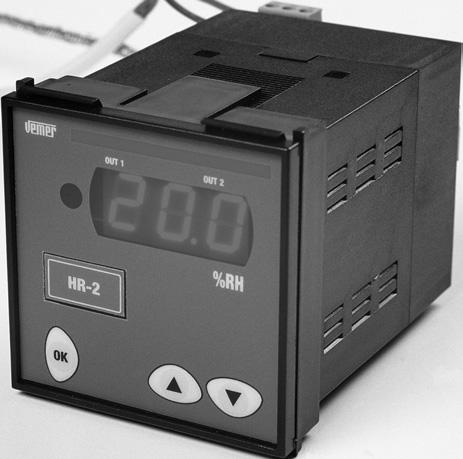
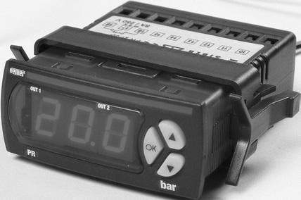
2 SAFETY WANINGS During the installation and operation of the instrument, follow the instructions set out below: 1) The instrument should be installed by a skilled operator. 2) Strictly follow the connection diagrams when installing the instrument. 3) Do not power or connect the instrument if any part of it is damaged. 4) Before touching the terminals, make sure the wires to be connected to the instrument are not live. 5) The connection cables should be able to resist the maximum operating temperature (Tmax), obtained from the sum of the maximum ambient temperature (Ta) a temperature of 20 C (Tmax= Ta 20 C). 6) The instruments guarantee a main insulation between the low voltage (250 V) and very low voltage parts. 7) Any outside switches connected to the controls should guarantee a minimum insulation at operating temperature of 250 V AC, or should be protected by equivalent insulation. 8) Contacts: all type 1C (CEI and variants). 9) The instruments require no maintenance. TECHNICAL SPECIFICATIS Series of digital regulators used for the most simple requirements in the control and regulation of humidity and pressure levels in air conditioning, heating and refrigeration systems Two dedicated base models for pressure and humidity control: - DIGITAL HUMIDITY EGULATOS H - DIGITAL PESSUE EGULATOS P Each single model has 1 probe for the connection of active sensors with standardised, and s The power supply to the active probe (linear sensor) comes directly from the instrument: 9 V DC available For each single model, the probe can be configured from the keyboard Available in versions with 1 or 2 relay s with contact in exchange egulators with 3 digit, seven segment and decimal point display elay intervention warning lamp Display range: Display resolution: 0.1 H or bar ( H or bar) and 1 H or bar (< -9.9 C and > 99.9 H or bar) Precision: ±0.5 % of the end of scale value ±1 digit (at an ambient temperature of 23 C) Sampling time: 0.5s
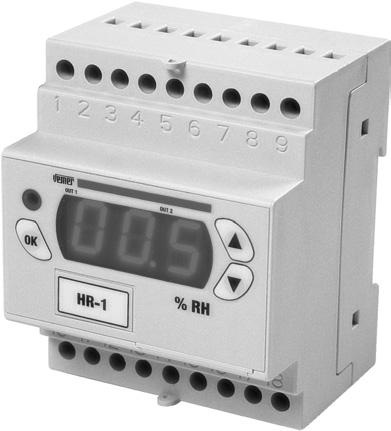
3 Parameter setting in digital mode: - Set point - Differential - Neutral zone - Output drive timing - delay function and time - Alarm delay / buzzer enable time - Probe calibration offset - esolution displayed - Measurement display filter (update speed) - Type of probe - Password - Operating modes (regulation): / Direct and/or everse action with or without neutral zone PWM Direct and everse action with or without neutral zone ALAM Special mode 2 independent set points : 1 (not versions H-..P7A, P-..P7A) for outside consensus for configurable function: outside alarm, regulator /, set-point switching, Direct/everce switching, etc. Acoustic and visual alarm signalling for: outside alarm (from digital ), probe alarm (malfunction), minimum or maximum alarm Infrared receiver with C-5 protocol for remote control (accessory available separately for remote programming) Available in the following fixing versions: 33x75 mm rear panel, 72x72 mm rear panel and modular 4 DIN : see table on the following page ated power: 3 VA for models with 33x75 mm rear panel fixing 4.5 VA for models with 72x72 mm and modular 4 DIN fixing Max absorption: 100 ma at 12 V - 50 ma at 24 V (1 channel) Operating temperature: 0 50 C Operating humidity: <80% Storage temperature: C (<80% H) Protection level: front panel IP54 (IP40 for the 4 DIN module version) terminals IP
4 ear panel 33x75 mm Code Model (*) n of Infrared tollerance relays receiver VM H-1P3D from 12 to 24 V AC/DC ± 10 1 YES YES VM H-1P3A from 100 to 230 V AC from 140 to 300 V DC ±15 1 YES YES VM H-2P3D from 12 to 24 V AC/DC ± 10 2 YES YES VM P-1P3D from 12 to 24 V AC/DC ± 10 1 YES YES VM P-1P3A from 100 to 230 V AC from 140 to 300 V DC ±15 1 YES YES VM P-2P3D from 12 to 24 V AC/DC ± 10 2 YES YES ear panel 72x72 mm Code Model (*) n of Infrared tollerance relays receiver VM H-1P7A 24/230 V AC ± 10 1 NO YES VM H-2P7A 24/230 V AC ± 10 2 NO YES VM P-1P7A 24/230 V AC ± 10 1 NO YES VM P-2P7A 24/230 VAC ± 10 2 NO YES Modular 4 DIN Code Model (*) n of Infrared tollerance relays receiver VM H-1DA 24/230 V AC ± 10 1 YES YES VM H-2DA 24/230 V AC ± 10 2 YES YES VM P-1DA 24/230 V AC ± 10 1 YES YES VM P-2DA 24/230 V AC ± 10 2 YES YES (*) AC power supply - frequency 50/60 Hz
5 DESCIPTI OF INSTUMENT Display A 3 digit led display with decimal point is used. For all the models, the display range is: - minimum display: -99 or -9.9 H or bar - maximum display: 999 or 99.9 H or bar elay intervention signalling lamp: Out 1: LED off if relay one is, on if relay one is, flashing if relay one in is waiting to become due to an active timing. Out 2: LED off if relay two is, on if relay two is, flashing if relay two in is waiting to become due to an active timing. Keys Three parameter setting keys are used: OK Confirm and parameter programming/display key. Key used to increase the parameter or go to the next parameter. Key used to decrease the parameter or leave the menu. ELECTICAL CNECTIS Adhere strictly to the instructions in the safety warnings and the Connection diagram section
6 GLOSSAY Set point (set or operating point) The set point is the value at which the appliance has to intervene to maintain the measurement controlled at the required level. Differential (or hysteresis) The differential is the maximum permitted variation from the set point for the measurement controlled prior to the intervention of the appliance. This is usually set in such a way as to prevent rapid oscillations in the measurement around the set point from causing frequent start-ups and shutdowns of the appliance or the driver connected to it. Direct action A regulator acts in direct mode when it limits the measurement as this increases. Direct Mode D Set Set Diff Measured Quantity everse action A regulator acts in reverse mode when it limits the reduction of the measurement controlled. everse Mode Set - Diff Set Measured Quantity Neutral or dead zone ( dead-band ) This indicates an interval of values around the set point in which the measurement regulated may oscillate without the activation of any. It is normally used in the appliances in which there is a strong inertia of the system, as a result of which the set point may be exceeded even after the driver has been switched off. Around the neutral zone, no Neutral Zone Mode is activated. Outside the neutral zone, the instrument operates in direct mode if the ZN ZN D measurement controlled increases, and in reverse if it Set - Diff () - ZN Set Set Diff (D) ZN decreases Measured Quantity
7 PWM operation (in proportion to time) This is a neutral zone type of operation in which the relays are activated periodically in impulse mode (the interval can be set, see the menu). The PWM procedure modulates the power in accordance with the position occupied by the measurement within the differential (the further we move away from the set point, the more the power increases). Important: we advise against using this method to drive compressors, due to the very close distance between start-up and shutdown. Direct operating mode [PO=0] In this mode, all the s operate in direct. The values of set point 1 [ST1] and differential 1 [DF1] have to be set. Hysteresis is to the right of the set point. If both s are used, the hysteresis for each is equivalent to half the differential. In this case, Set - Diff () - ZN 1 will be activated when the measurement controlled reaches the value [ST1][DF1]/2,at which point 2 will be deactivated. everse operating mode [PO=1] In this mode, all the s operate in reverse. The set point 1 [ST1] and differential 1 [DF1] values have to be set. Hysteresis is to the left of the set point. If both s are PO=1 mode used, the hysteresis for each OUT 2 is equivalent to half the differential. In this case, 1 will be activated when the measurement controlled reaches the value [ST1]-[DF1]/2,at which point 1 2 will be deactivated. D PO=0 mode PWM Mode ZN ZN Set Measured Quantity 1 2 s D 2 s D Set Diff (D) ZN OUT 2 D
8 Neutral zone operating mode [PO=2] In this mode, 1 operates in reverse and 2 in direct. The set point 1 [ST1], differential 1 [DF1] and neutral zone [DBN] values have to be set. These are parameters for both s. The regulator will tend to maintain the measurement controlled within the neutral zone. Outside of this, 2 will be activated if the measurement tends to increase, or 1 if it tends to decrease. If a single is present, this will operate in reverse, with the hysteresis shifted towards the left of the value [DBN]. PO=2 mode ZN 1 ZN ZN 2 s OUT 2 D PWM operating mode [PO=5] The regulation logic in this mode is the same as that with the neutral zone. It is therefore necessary to set the set point 1 [ST1], differential 1 [DF1] and neutral zone [DBN] values, which are parameters for both s. In this operating mode, the relays are activated impulsively, with an interval that can be set on the basis of the [TCL] value (see the menu). Within this interval, the relay will stay on for a period in proportion to the distance of the measurement regulated from the set point (plus the neutral zone, where applicable). In addition to the differential value, the relay will be active for 100% of the time. PO=5 mode OUT 2 ZN 1 ZN ZN 2 s D Operating mode with Direct/everse switching from digital. [PO=6] In this mode, both s operate in direct (with set point 1 and differential 1) or reverse (with set point 2 and differential 2) depending on the status of the digital. More precisely, in direct if the digital is open and in reverse if closed. The operating modes are the same as modes 0 and
9 It is therefore necessary to set both set point [ST1] and [ST2] and differential [DF1] and [DF2] values. open D PO=6 mode OUT 2 D D closed Diff. 2 Set 2 1 OUT 2 Diff. 2 Set 2 2 s Direct operating mode with switching of set point and differential from digital. [PO=7] In this mode, both s operate in direct, with set point 1/differential 1 or set point 2/differential 2 depending on the digital status. More precisely, with set point 1/differential 1 if the digital is open and set point 2/differential 2 if closed. The operating modes are the same as mode 0. It is necessary to set both the set point [ST1] and [ST2] differential [DF1] and [DF2] values. open D PO=7 mode OUT 2 D D closed OUT 2 D D D Diff. 2 Diff. 2 Set 2 1 Set 2 2 s
10 everse operating mode with set point and differential switching from digital [PO=8] In this mode, both s operate in reverse, with set point 1/differential 1 or set point 2/differential 2, depending on the status of the digital. More precisely, with set point 1/differential 1 if the digital is open and set point 2/differential 2 if closed. The operating modes are the same as mode 1. It is necessary to set both values of the set points [ST1] and [ST2] and differentials [DF1] and [DF2]. PO=8 mode open OUT 2 closed Diff. 2 Set 2 1 OUT 2 Diff. 2 Set 2 2 s Operating mode with channels 1 and 2 in reverse with set point 1 and differential. 1 and direct with set point 2 and differential 2 [PO=9] respectively. In this mode, 1 operates in reverse and 2 in direct. It is necessary to set the values of set point 1 [ST1] and differential 1 [DF1] for 1, and set point 2 [ST2] and differential 2 [DF2] for 2. The operating modes are the same as modes 0 and 1. If there is a single, this will operate in reverse. PO=9 mode OUT 2 D 1 Diff. 2 Set 2 2 s Alarm operating mode [PO=10] In this mode, 1 operates in reverse (with neutral zone), and 2 is dedicated to the alarm. It is necessary to set the values of set point 1 [ST1],
11 differential 1 [DF1] and the neutral PO=10 mode zone [DB1] for 1 and all the DFA DFA alarm menu parameters for 2. alarm The maximum alarm will be activated when the value [ST1][HIA] is reached and will alarm be deactivated at value LOA HIA [ST1][HIA]-[DFA]. The minimum Alarm alarm will be activated when the value [ST1]-[LOA] is reached and will be deactivated at value [ST1]-[LOA][DFA]. When there is a single, this will be dedicated to the alarm in the same way. OPEATI Normal operation The appliance operates in this way when no parameters are being programmed. In this status, the instrument carries out the regulation on the basis of the temperature measured and the parameters set. The following information is displayed: The quantity measured by the sensor The status of s OUT1 and OUT2 SETTING THE EGULATI PAAMETES There are two types of programming for the setting of the regulation parameters: - Simplified programming - Advanced programming Note: to reset the default values set in the factory, switch on the instrument while holding down the OK key. Simplified programming This is used to modify the regulation menu [EG] parameters only. Access is gained to this type of programming by pressing the OK key. Depending on the operating mode previously selected (see the system menu [SYS]), the following parameters can be modified: set, differential (/ regulation) set, differential, neutral zone (/ regulation with neutral zone) set, differential, neutral zone (PWM regulation) Use the up ( ) key to scroll through the parameter labels in a circular sequence
12 Press the down ( ) key at any time to leave the menu and return to normal operation (this also happens if no key is pressed for at least 40 seconds). Press OK to switch between the display of the parameter label and its numerical value. To modify a parameter: - from the display of its label or value, press OK and hold down for at least three seconds - the display will start to flash and will show the parameter value - use the up ( ) and down ( ) keys to increase or reduce the value - press OK to confirm the parameter and leave the modification (the display will stop flashing) Note: if no key is pressed for at least 40 seconds, the instrument leaves the parameter modification without memorising the changes made. During the display and modification of the parameters, the instrument will continue to operate with the previously set parameters. If password 1 is enabled (access password to protect the settings entered-see system menu), when the OK key is pressed from normal status the message will appear. To set the parameters, enter the previously set password (a number from 0 to 255) with the up ( ) and down ( ) keys and press OK to confirm. If the password is entered correctly, the label of the first menu will appear. Otherwise, the system will return to normal status. Advanced programming Access is gained to advanced programming from normal status by pressing and holding down the p and q keys for at least 3 seconds. Note: to reset the default values set in the factory, switch on the instrument while holding down the OK key. These parameters are grouped into eight menus, by type: 1) egulation (indicated with [EG]): set point, differential, neutral zone 2) Output (indicated with [OUT]): drive times, PWM cycle time 3) (indicated with [ING]): function, delay time 4) Alarm (indicated with [AL]): status in probe alarm, minimum/maximum shift, differential, delay time, buzzer enable 5) Display (indicated with [DSP]): set point limits, probe offset, resolution, measurement filter 6) Sensor (indicated with [SNS]): type of sensor, sensor parameters 7) System (indicated with [SYS]): password, modification enable, operating mode 8) Advanced (indicated with [ADD]): dependence, type, entry, differential/logic All the parameters inside the menus and their values are listed in the section that follows. - Use the up ( ) to scroll through the eight menus in sequence - To enter the menu required, press OK
13 - Inside each menu, it is possible to scroll through the labels of the parameters that can be modified by pressing up ( ).To display the value of the parame ter, press OK (press OK a second time to return to the display of the para meter label). -To modify the parameter value, hold down OK for at least 3 seconds. - The parameter value will start to flash and it will be possible to increase or decrease it with the up ( ) and down ( ) keys. - To confirm the value set, press OK. The parameter will stop flashing and the new value will be displayed. - It is possible to return to normal operation at any time by pressing down ( ) (or if no key is pressed for at least 40 seconds). Note: if no key is pressed for at least 40 seconds, the instrument leaves the parameter modification without memorising the changes made. Note: During the display and modification of the parameters, the instrument will continue to operate with the previously set parameters. If password 2 is enabled (access password for the protection of the settings-see system menu), when the up ( ) and down ( ) keys are held down for three seconds from normal status, the message will appear. To set the parameters, enter the previously set password (a number from 0 to 255) with the up ( ) and down ( ) keys and press OK to confirm. If the password is entered correctly, the label of the first menu will appear. Otherwise, the system will return to normal status. PAAMETE MENU To simplify the programming of the instruments, the parameters are grouped into various menus, in the following order: [EG] regulation menu [OUT] menu [ING] outside menu [AL] alarm menu [DSP] display menu [SNS] sensor menu [SYS] system menu [ADD] special parameter menu (for special operating mode only)
14 Description of parameters Inside the tables, the labels are presented in the same order as they appear in the various menus of the instrument. [EG] regulation menu Labels of parameters that Description unit Parameter values default notes can be modified min max ST1 set point 1 H or bar LO1 HI (1) DF1 differential for set point 1 H or bar ST2 set point 2 H or bar LO2 HI (2) DF2 differential for set point 2 H or bar (2) DBN neutral zone (dead band) H or bar (2) Notes: (1) for the values LO1/LO2 and HI1/HI2, see the display menu [DSP] (2) parameter active only if the operating mode permits [OUT] menu Labels of Parameter parameters that Description unit values default notes can be modified min max ET Time handling on relay enable (3) D Minimum time between 2 start-ups of the same relay min (4) TOF Minimum relay time min (5) T Minimum relay time min (6) INI Initial delay from instrument start-up min (7) TCL PWM cycle time sec (8) Notes: (3) This parameter enables the handling of the times defined by D, TOF and T for each channel, in the following ways: 0 timing not enabled for either relay 1 timing enabled for relay 1 only 2 timing enabled for relay 2 only 3 timing enabled for relay 1 and 2 s (4) this parameter limits the number of start-ups per hour for the driver connected to the instrument (this parameter is frequently used for compressors, for example) (5) the minimum time for which the should remain (6) timing enabled for relay 1 only
15 (7) the delay time for the driving of the s from the instant of instrument reset (8) the period that can be set for PWM regulation. This item is displayed only if the operating mode selected is PO=5 (see system menu). [ING] outside menu Labels of parameters that Description unit Parameter values default notes can be modified min max TID function (9) DID delay min (10) SUI Output status with digital active (open) (11) Notes: (9) The values that can be set are: 0 Not active 1 Outside alarm (with contact open) with delay time DID and automatic reset at the end of the alarm. The status becomes SUI 2 Outside alarm (with contact open) with manual reset 3 The operates as a switch: instrument on with contact closed and off with contact open The digital function is excluded when one of the following operating modes is selected inside the system menu [SYS]: mode=6, mode=7 and mode=8 (10) This is the delay after which the instrument responds to a signal from the digital (11) When the digital is active and a time period DID has lapsed, the s take on the following states: 0 Both relays 1 elay 1 and relay 2 2 elay 1 and relay 2 3 Both relays
16 [AL] alarm menu Labels of parameters that can be modified SUA Description unit Parameter values default notes min max Output status in probe alarm condition (12) LOA Minimum alarm shift H or bar (13) HIA Maximum alarm shift H or bar (13) DFA Alarm differential H or bar TA Alarm activation delay time min SOU Buzzer enable - no yes no (14) EAC Alarm messages in timing enable - no yes no (15) Notes: (12) This is the status taken on by the s in probe alarm condition (see note 11) (13) This value is added to or subtracted from the set point defined for the maximum or minimum alarm respectively (14) If yes, the acoustic signal of the key and the buzzer are enabled in alarm condition. If no, both of these are disabled. (15) If yes, the type of alarm is also displayed during its timing. If no, the type of alarm is displayed only at the end of the timing [DSP] display menu Labels of parameters that Description unit Parameter values default notes can be modified min max LO1 Lower limit of set point 1 H or bar -99 HI1-99 HI1 Upper limit of set point 1 H or bar LO LO2 Lower limit of set point 2 H or bar -99 HI2-99 (16) HI2 Upper limit of set point 2 H or bar LO (16) SOF Probe calibration offset H or bar (17) IS esolution displayed flag HI LO HI (18) UNI Temperature measurement unit flag C F C (19) FIL Measurement filter flag no yes yes (20) Notes: (16) parameter active only if the operating mode permits (17) this value is added to the measurement to compensate for imprecision (18) this is the resolution at which the measurement is displayed: 0.1 if HI or 1.0 if LO
17 (19) Important: this parameter should not be modified. If the measurement unit is changed, the parameters set are not converted automatically, but have to be re-calibrated (20) if the parameter is set to yes, a mobile average is taken of 8 measurement values (4 seconds approx.). If no, this average is not calculated [SNS] sensor menu Labels of parameters that Description unit Parameter values default notes can be modified min max TY0 Sensor type (21) ILO Minimum value of current/voltage scale H or bar (22) IHI Maximum value of current/voltage scale H or bar (22) Notes: (21) the values of the default parameter are listed below: Linear sensors Type of sensor Display message 0-20 ma (*) 020 (*) 4-20 ma V 0-1 (*) the instrument is set to this parameter by default [SYS] system menu Labels of parameters that Description unit Parameter values default notes can be modified min max PS1 password (23) PS2 password (23) NEN Parameter modification enable - yes no yes (24) PO Operating mode (25) Note: (22) the password is enabled if the parameter is different from 000 (23) if set to no, it is not possible to modify all the other parameters, only to display them (24) the following operating modes are available: 0 channels 1 and 2 in direct mode with set point 1 and 1 (hysteresis to the right of the set point)
18 1 channels 1 and 2 in reverse with set point 1 and differential 1 (hysteresis to the left of the set point) 2 neutral zone with channel 1 in reverse and channel 2 in direct with set point 1 and differential 1 3 as mode 0 but with differential centred on the set point 4 as mode 1 but with differential centred on the set point 5 PWM regulation with channel 1 in reverse and channel 2 in direct with set point 1 and differential 1, and neutral zone where applicable 6 switching between s in direct (with set-point 1 and differential 1) and s in reverse (with set-point 2 and differential 2) from digital 7 s in direct with switching between set-point 1/differential 1 and set-point 2/differential 2 from digital 8 s in reverse with switching between set point 1/differential 1 and set-point 2/differential 2 from digital 9 channel 1 in reverse with set-point 1 and differential 1 and channel 2 in direct with set-point 2 and differential 2 10 if one channel: alarm operation; if two channels: channel 1 in reverse (with set-point 1, differential 1 and neutral zone) and channel 2 in alarm operation 11 refrigeration mode (CANNOT BE USED) 12 special mode [ADD] special parameter menu Labels of parameters that Description unit Parameter values default notes can be modified min max DP0 Output 1 dependence (26) TI0 On/off or PWM 1 type (27) DB0 Neutral zone (28) IN0 Entry 1 % (29) DF0 Logical differential 1 % (30) DP1 Output 2 dependence (26) TI1 On/off or PWM 2 type (27) DB1 Neutral zone (28) IN1 Entry 2 % (29) DF1 Logical differential 2 % (30) Notes: (25) the parameter defines in what mode an depends on a set-point or an alarm mode. The values take on the following meanings: 0 not active 1 relates to set-point 1 2 relates to set-point
19 3 switching between in direct (with set-point 1 and differential 1) and in reverse (with set-point 2 and differential 2) through digital (open-direct, closed-reverse) 4 switching between set-point 1/differential 1 and set-point 2/differential 2 through digital (open-set 1, closed-set 2) 5 associated with maximum alarm for set-point 2 6 associated with minimum alarm for al set-point 2 7 associated with maximum alarm for set-point 1 8 associated with minimum alarm for al set-point 1 9 associated with maximum/minimum alarm for set-point 1 10 associated with maximum/minimum alarm for set-point 2 (26) defines whether the type of regulation is / (value 0) or PWM (value 1) (27) indicates whether the neutral zone is present (value 1) or not (value 0) (28) indicates the switching point of the relay with respect to the set-point defined by the dependence parameter: the switching point is calculated by adding a percentage IN0 (from -100% to 100%) to the set-point of the differential (29) indicates the switching point of the relay with respect to the point where the switching took place. The switching point is calculated by adding to the point a percentage DF0 (from -100% to 100%) of the differential. Note: the default values of these parameters depend on the operating mode and number of channels, as set out in the table below: 1 Channel Operating mode Parameter IN * DF * IN * DF * Channels Operating mode Parameter IN * DF * IN * DF * * The default values for mode 6 are the same as those of modes 0 or 1, depending on whether the s are operating in direct or reverse
20 EO MESSAGES Due to alarms or malfunctions, the display of the measurement may alternate with the display of messages describing the type of alarm. The table below describes the alarm/error messages used. Message Type of error Output status E0 Sensor 1 disconnected or in short circuit As parameter [SUA] E1 Sensor 2 disconnected or in short circuit As parameter [SUA] ALL Minimum alarm Depends on operating mode ALH Maximum alarm Depends on operating mode ALE Outside alarm As parameter [SUA] egulation inhibited by outside As parameter [SUA] Note: the message is not alternated with the measurement, but remains fixed on the display
21 EFEENCE STANDADS For safety: CEI-EN For electromagnetic compatibility: CEI-EN CEI-EN CEI-EN CEI-EN
22 33x75 mm EA PANEL DIMENSIS OK H-1P3D P-1P3D 75 65, H-1P3A P-1P3A H-2P3D P-2P3D 75 OK
23 r 33x75 mm EA PANEL DIAGAMS Model Connection diagram ~ H-1P3A P-1P3A elay 8(1) A/250 V~ Probe - Probe Probe Self-powered probe 3 wires probe to be powered 2 wires probe to be powered H-1P3D P-1P3D elay 8(1) A/250 V~ P o w e s u p p l y~ 3 wires probe to be powered - Probe 2 wires probe to be powered Probe Self-powered probe Probe elay 2 8(1) A/250 V~ H-2P3D P-2P3D elay 1 8(1) A/250 V~ Power ~ suppl y Probe - Probe Probe Self-powered probe 3 wires probe to be powered 2 wires probe to be powered
24 72x72 mm EA PANEL DIMENSIS H-..P7A P-..P7A OK x72 mm EA PANEL DIAGAMS Model Connection diagram 230 V~ 5 ~ z H ~ 24 V~ 6 0 H z H-1P7A P-1P7A elay 8(1) A/250 V~ Probe - 3 wires probe to be powered Probe 2 wires probe to be powered Probe Self-powered probe 230 V~ ~ z 6 0 H ~ 24 V~ 6 0 H z H-2P7A P-2P7A elay 1 8(1) A/250 V~ elay 2 8(1) A/250 V~ Probe - 3 wires probe to be powered Probe 2 wires probe to be powered Probe Self-powered probe
25 z 4 DIN DIMENSIS MODULAS H-..DA P-..DA 87 OK DIN DIAGAMS MODULAS Model Connection diagram 230 V~ ~ 24 V~ 6 0 H z ~ z 6 0 H elay 8(1) A/250 V~ 8 9 H-1DA P-1DA Probe - Probe Probe Self-powered probe 3 wires probe to be powered 2 wires probe to be powered 230 V~ 5 ~ 24 V~ H 5 ~ z H elay 2 8(1) A/250 V~ elay 1 8(1) A/250 V~ H-2DA P-2DA Probe - Probe Probe Self-powered probe 3 wires probe to be powered 2 wires probe to be powered

26 - 52 -
APPENDIX APPENDIX A 1
 A 1 SPECIFICATIONS Ratings Supply voltage 100 to 240 VAC, 50/60 Hz 24 VAC, 50/60 Hz/24 VDC Operating voltage range 85 to 110% of rated supply voltage Power consumption 7VA 4VA/2.5W Sensor input Thermocouple
OVEN INDUSTRIES, INC. Model 5C7-362
 OVEN INDUSTRIES, INC. OPERATING MANUAL Model 5C7-362 THERMOELECTRIC MODULE TEMPERATURE CONTROLLER TABLE OF CONTENTS Features... 1 Description... 2 Block Diagram... 3 RS232 Communications Connections...
MPS SERIES. INSTALLATION and TECHNICAL MANUAL MPS 4 MPS 5 MPS 9 4 PV
 MPS SERIES INSTALLATION and TECHNICAL MANUAL PV AT M AL1 AL2 SP1 4 PV AT SV SV M SP1 SP2 AL1 AL2 AL3 P SP2 P MPS 4 MPS 5 PV M AL1 SV AT SP1 AL2 SP2 AL3 P MPS 9 ITALMEC ELETTRONICA P.O. Box 34 40069 ZOLA
ENGLISH. General features 2. Technical features 3. Installation 10. Preliminary operations 12. Front panel description 13.
 LDI 35 OPERATING INSTRUCTIONS General features 2 Technical features 3 Installation 10 Preliminary operations 12 Front panel description 13 Operating mode 15 Important: We suggest you keep the original
EIB/KNX Switch Actuators. User manual
 EIB/KNX Switch Actuators User manual IT KNT 004 IT KNT 012 Tel.: +34943627988 E-mail: knx@dinuy.com Web: www.dinuy.com Contents 1. Introduction --------------------------------------------------------------------------------------------------------------
WIRELESS DIMMER FOR HEATING
 TELECO AUTOMATI SRL - Via dell Artigianato, 16-31014 Colle Umberto (TV) ITALY TELEPHE: ++39.0438.388511 FAX: ++39.0438.388536 - www.telecoautomation.com This document is the property of Teleco Automation
UNICONT. PMG-400 Universal controller and display unit USER'S AND PROGRAMMING MANUAL 1. pmg4111a0600p_01 1 / 24. ST edition
 UNICONT PMG-400 Universal controller and display unit USER'S AND PROGRAMMING MANUAL 1 ST edition pmg4111a0600p_01 1 / 24 TABLE OF CONTENTS 1. GENERAL DESCRIPTION... 3 2. ORDER CODE... 3 3. TECHNICAL DATA...
Electronic Controls For general purpose and multi stages controls. Features and Benefits
 Refrigeration Controls Catalogue Catalog Section 9 Product Bulletin MS1/4 Electronic Controls For general purpose and multi stages controls Introduction This range of versatile controls is intended for
Instruction manual. art Installation manual
 Instruction manual art. 01521 Installation manual Contents GENERAL FEATURES AND FUNCTIONALITY from page 4 ETS PARAMETERS AND COMMUNICATION OBJECTS from page 6 COMMUNICATION OBJECTS GENERAL FEATURES AND
BU: EPBP GPG: DIN Rail Products Devices for the permanent control of insulation on supply lines for medical locations ISOLTESTER-DIG-RZ/RS/PLUS
 INSTRUCTION MANUAL BU: EPBP GPG: DIN Rail Products Devices for the permanent control of insulation on supply lines for medical locations ISOLTESTER-DIG-RZ/RS/PLUS 1/23 More information than that reported
The appliance is fitted with a 3-digit display in order to show the room temperature and the 2 + and - key parameters for the programming functions.
 P.I. Proportional-integral temperature controller with limits function DB-TA-31A WARNINGS Installation and maintenance operations must be carried out by qualified personnel, with the appliance disconnected
SERVICE-MANUAL ROOM TEMPERATURE CONTROLLER NEA 230V / 24V. Construction Automotive Industry
 ROOM TEMPERATURE CONTROLLER NEA 230V / 24V Construction Automotive Industry ROOM TEMPERATURE CONTROLLER NEA 230V / 24V TABLE OF CONTENTS 1....... Information and safety guidelines......................................................
Analogue temperature controllers
 Analogue temperature controllers CT8A Input by J-K thermo-couple or by thermo-resistance Pt 00 (-wire) regulation modes : ON/OFF or proportional derivative selected by wiring Relay output Specifications
Fuzzy Temperature Controllers E5AF
 Fuzzy Temperature Controllers 1/4 DIN Controller Combines Fuzzy and PID Control For Fast Response to Process Disturbances Advanced PID control provides optimal response during start-up and steadystate
Please enter the identity code of your device here!
 Operating Instructions DULCOMETER D2C Part 2: Adjustment and Operation, Measured Variables ph/chlorine dioxide ProMinent D2C2-001-pH/CIO2-GB ph/clo 2 7.20 ph 0.45 ppm DULCOMETER STOP STAR T ph/clo 2 7.20
K-BUS Switch Actuator
 K-BUS Switch Actuator User manual-ver. 2 KA/R0416.1 KA/R0816.1 KA/R1216.1 Contents Contents... 2 1. Introduction... 3 1.1 Product and function overview... 3 2. Technical Properties... 3 3. Commissioning...
Motor 1- GENERAL DESCRIPTION
 1- GENERAL DESCRIPTI TELECO AUTOMATI SRL - Via dell Artigianato, 16-31014 Colle Umberto (TV) ITALY TELEPHE: ++39.0438.388511 FAX: ++39.0438.388536 This document is the property of Teleco Automation Srl
DIGEM f 96 x 48 EK. Applications. Description
 3-349-002-03 1/7.98 Front panel dimensions: 96 x 48 mm LED display: red or green, 14 mm high Max. display range: 19 999 to + 32 765 Modular connectors for flexible use Simple adjustments at front panel
sw rev. 55B DEVICE FOR THE PERMANENT CONTROL OF INSULATION ON THE SUPPLY LINES IN MEDICAL PRACTICE PLACES INSTALLATIONS
 INSTRUCTIONS MANUAL IM831-U v0.92 HRI-R40W sw rev. 55B DEVICE FOR THE PERMANENT CONTROL OF INSULATION ON THE SUPPLY LINES IN MEDICAL PRACTICE PLACES INSTALLATIONS INDEX: GENERAL TYPES ACESSORIES AND OPTIONS
1800 Series Attachable Loop-Powered Digital Indicators Operating Manual
 1800 Series Attachable Loop-Powered Digital Indicators Operating Manual 1010 West Bagley Road, Berea, Ohio 44017 P 440.243.0888 F 440.243.3472 www.noshok.com Index 1 INTRODUCTION 3 2 SAFETY REGULATIONS
Computer-14d - xx - 144a
 POWER FACTOR REGULATOR Computer-14d - xx - 144a INSTRUCTION MANUAL ( M 981 602 / 98B ) (c) CIRCUTOR S.A. -------- POWER FACTOR REGULATOR COMPUTER- 14d --------- Page 2 1.- POWER FACTOR REGULATORS COMPUTER-14d-144a
METRAClip87 and 88 Clamp Multimeters
 3-349-795-03 1/7.14 Current and frequency measurement via clamp meter: METRAClip87: 1500 A AC TRMS and 1500 A DC METRAClip88: 2000 A AC TRMS and 3000 A DC Multimeter functions via connector sockets: V
INSTRUCTIONS MANUAL DEVICE FOR THE PERMANENT CONTROL OF INSULATION ON THE SUPPLY LINES IN MEDICAL PRACTICE PLACES INSTALLATIONS HRI-R40W
 Page 2 / 16 INDEX: GENERAL TYPES ACESSORIES AND OPTIONS INSTALLATION WIRING DIAGRAMS CONNECTING TERMINALS DIAGRAMS WIRING DIAGRAM DESCRIPTION WORKING DESCRIPTION AND KEYBOARD WORKING DESCRIPTION AND PROGRAMMING
ALPTEC POWER FACTOR CONTROLLER
 ALPTEC POWER FACTOR CONTROLLER ALPTEC3 ALPTEC5 ALPTEC7 ALPTEC12 0 REF : 2008-ALPTEC3.5.7.12-01-ANG CONTENTS I GENERAL INFORMATION. 2 II WAYS TO SET UP THE CONTROLLER.. 4 III OPERATING MODE..6 IV ADVANCED
SYL-2362A2 PID TEMPERATURE CONTROLLER
 SYL-2362A2 PID TEMPEATUE CONTOLLE INSTUCTION MANUAL Version 2.4 Caution This controller is intended to control equipment under normal operating conditions. If failure or malfunction of it could lead to
AHC-XP. Dewpoint-guided Power Controller for Glass and Handrail Heaters. Front view. Characteristics
 Dewpoint-guided Power Controller for Glass and Handrail Heaters Front view Characteristics Dew point-guided power controller for cost-optimized operation of glass and handrail heaters Digital display of
Operating Instructions
 4XH35QB151210 Small General Frequency Converter Operating Instructions 220V 0.75KW 5.5KW 400V 0.75KW 15KW Please read the instruction carefully and understand the contents so that it can be installed and
ATS-I USER MANUAL. Tecnoelettra srl Dal Via Vioni Dimo, S.Rocco di Guastalla (RE)
") USER MANUAL ATS-I Tel.+39.0522.832004 P1/17 ATS-I User manual Fax.+39.0522.832012 Tecnoelettra_EN.doc P.1/17 Index General description...3 Electrical specifics...3 Device operative logic...4 Manual mode...4
USER MANUAL ATS-I Tel.+39.0522.832004 P1/17 ATS-I User manual Fax.+39.0522.832012 Tecnoelettra_EN.doc P.1/17 Index General description...3 Electrical specifics...3 Device operative logic...4 Manual mode...4
This document is the property of Teleco Automation Srl who reserves all reproduction and copying rights
 1- GENERAL DESCRIPTION Electronic for the remote control of tubular motors for roller blinds, rolling shutters, doors with limit switch inside or outside the motor, radio receiver section with transmitter
DC Voltage Hawk II H235 Series Advanced Digital Panel Meter
 % DC Voltage Hawk II H35 Series Advanced Digital Panel Meter Easily Programmed from the Front Panel User-Friendly Software Functions Include: Password Display Scaling Decimal Point Selection Set Point
TEMPERATURE CONTROLLER RE21 TYPE
 TEMPERATURE CONTROLLER RE21 TYPE USER S MANUAL 1 2 Contents 1. Application... 5 2. Controller set... 5 3. Preparation of the controller to work... 6 3.1. Safety... 6 3.2. Controller installation... 9 3.3.
Please enter the identity code of your device here!
 Operating Instructions DULCOMETER D1C Part 2: Adjustment and Operation, Measured Variable Conductive Conductivity ProMinent D1C2-Leit.-001-GB Conductivity 100 µs/cm DULCOMETER STOP START Conductivity 100
Protection and safety SQZ3 phase and sequence relay
 SQZ3 phase and sequence relay Supply voltage [Vn] 400 V a.c. Frequency [Hz] 0/60 SQZ3 2CSC4001F0201 Contact type [A] 1 CO, 20 V, 10 A (cos =1) safety switching Minimum voltage adjustment trimmer [%] 100
FLOMID-MX Control unit for electromagnetic flowmeters USERS MANUAL. instrumentación para fluidos. Realitzat: Revisat R+D Electrònic: Aprovat: Data:
 instrumentación para fluidos FLOMID-MX Control unit for electromagnetic flowmeters USERS MANUAL Realitzat: Data: Revisat R+D Electrònic: Data: Revisat Of. Comercial: Data: Aprovat: Data: R-MI-Flomid-MX
Advanced Test Equipment Rentals ATEC (2832)
") Established 1981 Advanced Test Equipment Rentals www.atecorp.com 800-404-ATEC (2832) 2 SPECIFICATIONS Model TOS8700 I TOS8750 Test Applied voltage AC/DC voltage 0-3/0-10 kv I 0-1.5/0-5 kv Output 500 VA
Established 1981 Advanced Test Equipment Rentals www.atecorp.com 800-404-ATEC (2832) 2 SPECIFICATIONS Model TOS8700 I TOS8750 Test Applied voltage AC/DC voltage 0-3/0-10 kv I 0-1.5/0-5 kv Output 500 VA
LS3300 AC Power Calibrator Simple Adjustment Procedure for Voltage, Current, and Frequency
 User s Manual AC Power Calibrator Simple Adjustment Procedure for Voltage, Current, and Frequency The instrument should be adjusted by a qualified engineer at a qualified facility with sufficient precision.
theben Fan Coil Actuator FCA 1 Fan Coil Actuator FCA 1 FCA Version: Jan-08 (Subject to change) Page 1 of 77
 Page 1 of 77") Fan Coil Actuator FCA 1 FCA 1 492 0 200 Version: Jan-08 (Subject to change) Page 1 of 77 Contents 1 Functional characteristics...4 1.1 Operation and display...5 1.2 Advantages of the FCA 1...5 1.2.1 Special
Fan Coil Actuator FCA 1 FCA 1 492 0 200 Version: Jan-08 (Subject to change) Page 1 of 77 Contents 1 Functional characteristics...4 1.1 Operation and display...5 1.2 Advantages of the FCA 1...5 1.2.1 Special
ENGLISH OPERATING INSTRUCTIONS. General Features 2. Technical Features 3. Installation 9. Preliminary Operations 11. Front Panel Description 12
 MDI40 OPERATING INSTRUCTIONS General Features 2 Technical Features 3 Installation 9 Preliminary Operations 11 Front Panel Description 12 Operating mode 15 Important: We suggest you keep the original packing
U S E R S M A N U A L
 U S E R S M A N U A L T H E R M O R E G U L A T O R T R 5 0 0 / T R 5 0 1 S E R I E S HUNDREDTHS VERSION ENGLISH V.1.2 TABLE OF CONTENTS -1- Introduction... page 2-2- Technical specifications -3- Description
Electronic fan speed regulators
 Electronic fan speed regulators Purpose The fan speed controller maintains the condensing pressure for fan-type condensers or fluid outlet temperatures for dry coolers, within prefixed values, for any
SPECIFICATION FOR OVERCURRENT RELAYS
 SPECIFICATION FOR OVERCURRENT RELAYS 1/9 1. Procedure A manufacturer willing to classify an overcurrent relay according to this specification should provide: A complete file providing a clear, unambiguous
USER S MANUAL. Manual for Panel Mount Process Indicator. HTA INSTRUMENTATION (P) LTD. Your One Stop for Instrumentation, Calibration & Service
 LTD. Your One Stop for Instrumentation, Calibration & Service") Member of SN Registrars (Holdings) Ltd 8327 USER S MANUAL Manual for Panel Mount Process Indicator EQ-DS8B-IRRB EQ-DS8B-IRRB HTA INSTRUMENTATION (P) LTD. Your One Stop for Instrumentation, Calibration
Member of SN Registrars (Holdings) Ltd 8327 USER S MANUAL Manual for Panel Mount Process Indicator EQ-DS8B-IRRB EQ-DS8B-IRRB HTA INSTRUMENTATION (P) LTD. Your One Stop for Instrumentation, Calibration
Simplified Operations for TM-3100 Series Digital Tachometer
 Simplified Operations for TM-3100 Series Digital Tachometer The TM-3100 series Digital Tachometers has the most fundamental function in rotational measurement of four standard models (rotation speed display,
7SD/7SH/7SM Temperature Controllers
 7SD/7SH/7SM Temperature ADVANTAGE EZ Series 7SD, 7SH, 7SM 1/16 DIN Temperature 3Digit LED Display Thermocouple and RTD Input Autotuning NEMA 4X Field onfigurable 100 to 40 Vac Switching Power Supply Programmable
Proximity Sensor Terminology
 The following descriptions refer to the European standard EN 60947-5-2. of 2007. The specifications given here are intended to be minimum performance values described by the standard. Alignment must not
INTEGRATED VOICE EVACUATION SYSTEM VM-3000 Series
 OPERATION MANUAL INTEGRATED VOICE EVACUATION SYSTEM VM-3000 Series VOICE ALARM SYSTEM AMPLIFIER VM-3240VA VOICE ALARM SYSTEM AMPLIFIER VM-3360VA VM EXTENSION AMPLIFIER VM-3240E VM EXTENSION AMPLIFIER VM-3360E
8000 SERIES PRECISION MULTIMETER VERIFICATION AND ADJUSTMENT GUIDE
 8000 SERIES PRECISION MULTIMETER VERIFICATION AND ADJUSTMENT GUIDE TRANSMILLE LTD. Version 1.1 : Apr 2015 TABLE OF CONTENTS PREPARING FOR CALIBRATION... 4 INTRODUCTION... 4 CALIBRATION INTERVAL SELECTION...
Temperature Controller model MFC-301/T-Dry. Version for Dry Transformers and Motors. Technical Manual. Licht
 Temperature Controller model MFC-301/T-Dry Version for Dry Transformers and Motors Technical Manual Licht Contents 1 Introduction 2 2 Operating principle 3 2.1 General principle 3 2.2 RTD operation 3 3
SUPPLY NETWORK ANALYZER CVM-96 SERIES
 SUPPLY NETWORK ANALYZER CVM-96 SERIES (Power Demand) INSTRUCTION MANUAL ( M 981 326 / 00B - GB) (c) CIRCUTOR S.A. ----- Supply network analyzer CVM-96 ------ User's manual --- Page No. 1 CVM-96 SUPPLY
Device manual Multifunction display and evaluation system FX 360. Mode/Enter
 Device manual Multifunction display and evaluation system FX 360 7390275 / 08 07 / 2009 Mode/Enter Set Safety instructions This manual is part of the unit. It contains texts and diagrams for the correct
Fan Coil Actuator FCA 2
 Fan Coil Actuator FCA 2 FCA 2 4920210 Updated: Feb-16 (subject to changes) Page 1 of 89 Contents 1 Function description... 4 1.1 Operation and display... 5 1.2 Advantages of the FCA 2... 6 1.2.1 Special
RCMS460 and RCMS490 Series
 4 T M RCMS460 and RCMS490 Series Digital Multi-Channel Ground Fault Monitor / Ground Fault Relay Grounded and High-Resistance Grounded AC/DC Systems Technical Bulletin NAE1042060 / 04.2013 BENDER Inc.
Please enter the identity code of your device here!
 Operating Instructions DULCOMETER D1C Part 2: Adjustment and Operation, Measured Variable Ozone ProMinent D1C2-03-001-GB O 3 DULCOMETER STOP START O 3 DULCOMETER STOP START Type D Type W D1C A Please enter
6.9 Jump frequency - Avoiding frequency resonance
 E581595.9 Jump frequency - Avoiding frequency resonance : Jump frequency : Jumping width Function Resonance due to the natural frequency of the mechanical system can be avoided by jumping the resonant
1000TR. Instructions
 1000TR ph Instructions CONTENTS 1. INTRODUCTION... 2 1.1 COMMON INTRODUCTION... 2 1.2 PARTS & ACCESSORIES... 2 2. INSTALLATION... 3 2.1 CASING... 3 2.2 MOUNTING... 3 2.3 ELECTRICAL INSTALLATION... 3 2.3.1
General Specifications
 General Specifications GS 77J01Q08-01E Model VJQ8 Pulse to Analog Converter (Multi-function) (Isolated Single-output and Isolated Dual-output Types) General This plug-in type pulse to analog converter
5 Channel Multifunctional PWM Controller. HomLiCon LCH5T. Technical Specifications
 5 Channel Multifunctional PWM Controller Application Control of groups LED and LED strips Control of relays, small motors, fans, etc. Control models Technical Specifications Number of Channels 5 Color
C C1 C2 AL1 AL2 AL3. Micro-controller X. Model: PXR SEL PXR-4. Operation Manual. ECNO:406a
 C C1 C2 AL1 AL2 AL3 Micro-controller X Model: PXR PXR-4 SEL Operation Manual ECNO:406a Table of Contents 1 Part Names and Functions... 4 2 Operations... 5 2-1 Parameter list... 5 2-2 Basic operations...
937CU-DIFRQ_1 Installation Instructions. Universal Frequency Converter
 937CU-DIFRQ_1 Installation Instructions Universal Frequency Converter Bul. 937C Universal Frequency Converter Installation Instructions Symbols Used Warning Attention This symbol warns of possible danger.
Series Valve Temperature Controller. Instruction Sheet
 2013/10/03 Series Valve Temperature Controller Instruction Sheet Thank you very much for choosing Delta DTV series valve temperature controller. Please read this instruction sheet before using your DTV
R&D TECHNICAL SPECIFI
 INTRODUCTION Present document defines technical specs of a three phase UPS covering the power range from 20 to 30 kva ON-LINE DOUBLE CONVERSION Uninterruptible Power Supply Systems with forced ventilation
INSTRUCTION MANUAL. Power Factor Controller - 12 steps Model A12 NOKIAN CAPACITORS. Power Factor Controller A12
 INSTRUCTION MANUAL Power Factor Controller - 12 steps Model A12 NOKIAN CAPACITORS Power Factor Controller A12 1. CONTENTS 1. CONTENTS 1 2. FEATURES 2 3. INSTALLATION, CONNECTION AND APPLYING POWER 2 4.
SRC-110 Series Zone Controllers with Modbus RTU
 Product sheet CT2.142 Type SRC-110-MOD SRC-110 Series Zone Controllers with Modbus RTU The SRC-110 series controllers have been designed for zone heating and cooling control. The controllers have 3 analogue
AEROCONNECT 1B NA C Control manual
 AEROCONNECT 1B NA 11.3 C 03-01 Control manual EN CONTENTS PAGE 1 - IMPORTANT RECOMMENDATIONS 1.1 Power supply 1. Electronic board specifications 1.3 Caution 1.4 Earth 1. Sensor connections 1.6 Communication
Installation, Operation and Maintenance Manual
 M518 Rev. B Model 1030F Indicator-Totalizer Model 1030F Indicator-Totalizer Installation, Operation and Maintenance Manual Table of Contents General... 1 Installation... 1 Operation... 7 Programming...
PHOENIX CONTACT - 03/2007
 Inline Function Terminal for Pulse Width Modulation and Frequency Modulation N AUTOMATIONWORX Data Sheet 6920_en_01 1 Description PHOENIX CONTACT - 03/2007 $ ' ) The terminal is designed for use within
JPQ2 PULSE ACCUMULATOR
 INSTRUCTION MANUAL PULSE ACCUMULATOR (field-programmable; built-in excitation) MODEL JPQ JPQ BEFORE USE... Thank you for choosing M-System. Before use, check the contents of the package you received as
Use of the application program. Contents. instabus EIB Application program description. September S2 Room temperature controller
 Use of the application program Product family: Product type: Manufacturer: Heating, Air conditioning, Ventilation Thermostat Siemens Name: Room temperature controller IKE 250 DELTA millennium Order no.:
Technical Datasheet. True RMS Digital Protection Relay. Line Monitoring Relay
 Technical Datasheet RELAY-1 RELAY-2 k V Hz RESET ABH TEST True RMS Measurement True RMS Digital Protection V/Hz is used to protect against Over Voltage, Under Voltage, Phase Unbalance, Phase Sequence detection,
IN ELECTRICAL ENGINEERING - I C M E T CRAIOVA
 Taking into account that power transformer is the major item of equipment in power systems, its correct operation is vital to system operation. It is well known that transformer failures are sometimes
Fig Input connections, outputs and power supply
 Fig. 01 - Input connections, outputs and power supply the loaded optional features. Those channels are configured by the user to act as control outputs, alarm outputs, LBD Function or or retransmission.
CONTROL MANUAL. Dry-Pic 09PE - 09VE
 CONTROL MANUAL Dry-Pic 09PE - 09VE Translation of the original document 003, 04.01 EN CONTENTS PAGE 1 - IMPORTANT RECOMMENDATIONS 1.1 Power supply 1. Electronic board specifications 1.3 Caution 1.4 Earth
C4000. inline control. Photometric Converter. Real-time photometric converter. Factory zero for scattered light sensors
 C4000 Photometric Converter inline control Real-time photometric converter Factory zero for scattered light sensors Simultaneous operation of up to four inline sensors Process control functions via Remote
Digital Panel Meters DC/AC Current and Voltage Indicator/Controller Type LDM40
 Digital Panel Meters Current and Voltage Indicator/Controller Type LDM40 Multi-input instrument 4-DGT LED 0.1% RDG basic accuracy TRMS AC current and voltage measurements AC/DC current measurements: selectable
Operation Instruction Manual KAM-TC1000. Precision Temperature Controller
 Kamweld Industries Inc. Operation Instruction Manual KAM-TC1000 Precision Temperature Controller Introduction Thank you for purchasing Kamweld's Percision temperature controller, KAM-TC1000. We sincerely
Earth 2/3 MI 2126 Instruction Manual Version 1.0, Code No
 Earth 2/3 MI 2126 Instruction Manual Version 1.0, Code No. 20 750 190 Distributor: Manufacturer: METREL d.d. Ljubljanska cesta 77 1354 Horjul Slovenia web site: http://www.metrel.si e-mail: metrel@metrel.si
10/2 Product overview. 10/3 4AC3 0, 4AC3 1 bell transformers. 10/5 4AC AC3 6 transformers for permanent loads. 10/8 4AC2 4 power supply units
 BETA Switching Transformers, Bells and Socket Outlets /2 Product overview /3 4AC3 0, 4AC3 1 bell transformers /5 4AC3 4... 4AC3 transformers for permanent loads /8 4AC2 4 power supply units / 7LQ2 2 bells
TOS5300 SERIES Hipot Tester/Hipot Tester with Insulation Resistance Test
 A new standard for Hipot & Insulation resistance testing Applied to World-Wide input voltage TOS5301 TOS5300 TOS5302 TOS5300(ACW) TOS5301(ACW/DCW) TOS5302(ACW/IR) New low-cost standard model that provides
INSTRUCTION MANUAL Redox sensor M 1322 C
 INSTRUCTION MANUAL Redox sensor M 1322 C From version 2.01 2013 Controlmatik ABW d.o.o. 2 1. General... 7 1.1 Assembly... 8 1.2 Storage of Redox probes... 9 1.3 Connection to the electrical power supply...
Technical Datasheet. True RMS Digital Protection Relay. Voltage Protection Relay
 Technical Datasheet RELAY-1 RISHABH k V RESET True RMS Digital Protection Relay RELAY-2 TEST True RMS Measurement RISH Relay V is used to protect against Over Voltage, Under Voltage, Phase Sequence detection,
PROCESS & TEMPERATURE CONTROLLERS
 PROCESS & TEMPERATURE CONTROLLERS NOVA PD54 Series Thermocouple, RTD, & Process Inputs High Accuracy Auto-Tuning PID Heating & Cooling Models Universal Power Supply 1-24 VAC Up to 3 Relays & 2 Analog Outputs
TECHNICAL DATA SHEET. Safety and function tester GLP1-g. Standard model GLP1-g ELECTRICAL SPECIFICATION
 TECHNICAL DATA SHEET Safety and function tester GLP1-g Revision 2.7 / valid from July 2017 Standard model GLP1-g ELECTRICAL SPECIFICATION Supply voltage Mains frequency No load current consumption 110
POINTAX 6000L2 Point Recorder
 GOSSEN METRAWATT CAMILLE BAUER Special Features 6 measuring channels Last printed point visible from front Electrically isolated, earth-free measuring channels Process signals ranging from 0/4... 20 ma,
Multi-function (MI, ME, M2, M1) 2 NO (2 SPST-NO) 12 / / 400 3,000 1, / 0.3 / (5 / 5) AgNi
 2 NO (2 SPST-NO) 12 / / 400 3,000 1, / 0.3 / (5 / 5) AgNi") Features Special relay for alternating loads, for applications with pumps, compressors, air conditioning or refrigeration units 2 independent NO output, 12 A 4 functions 2 independent control signals,
Features Special relay for alternating loads, for applications with pumps, compressors, air conditioning or refrigeration units 2 independent NO output, 12 A 4 functions 2 independent control signals,
RISH EM 3490 SS Kilowatt Hour Energy Meter With Rs485 RISH EM 3490 SS. Application : Product Features: Indication: Pulse Indication:
 Application : RISH Master 3490 SS is a 96mm x 96mm panel mounted kilowatt hour meter it measures active energy with class 1.0 accuracy having auto-resetting 8 digit seven segment LED counter. The unit
Operating instructions. Combined pressure sensor PN /00 11/03
 Operating instructions R Combined pressure sensor PN 7080/00 /03 Contents afety instructions..................................... page 5 Controls and indicating elements.......................... page
DPF-MAC Auto power factor controller
 Digital Electric& Electronics System DPF-MAC Auto power factor controller MULTI POWER FACTOR AUTOMATIC MULTI POWER FACTOR AUTOMATIC Introduction DPF-MAC increases usage efficiency by controlling the power
SECULIFE SR PC Controllable Instrument for Measuring Safety-Relevant Characteristic Values of Electrical Devices /2.
 3-349-443-03 3/2.12 Applications Testing for the Electrical Safety of Electrical Medical Devices in Accordance with the German Medical Product Law (MPG) / MDD The test instrument is used for quick and
Modulating controlled actuators AME 10, AME 20, AME 30 AME 13, AME 23, AME 33 - with DIN EN certified safety function (spring down)
") Data sheet Modulating controlled actuators AME 10, AME 20, AME 30 AME 13, AME 23, AME 33 - with DIN EN 14597 certified safety function (spring down) Description AME 10 AME 13 AME 20, AME 30 AME 23, AME
Data sheet Modulating controlled actuators AME 10, AME 20, AME 30 AME 13, AME 23, AME 33 - with DIN EN 14597 certified safety function (spring down) Description AME 10 AME 13 AME 20, AME 30 AME 23, AME
HUMIDITY/TEMP. CONTROLLER/MONITOR
 HUMIDITY/TEMP. CONTROLLER/MONITOR Model : PHT-3109 Your purchase of this HUMIDITY/TEMP. CONTROLLER, MONITOR marks a step forward for you into the field of precision measurement. Although this METER is
Please enter the identity code of your device here!
 Operating Instructions DULCOMETER D2C Part 2: Adjustment and Operation, Measured Variables chlorine/chlorine ProMinent D2C2-001-chlorine/chlorine-GB CI 2 /Cl 2 0.50 ppm CLE 0.20 ppm CI DULCOMETER STOP
FEMA ELECTRÓNICA. Panel meter for TrueRMS measures of AC voltages and AC currents. Category
 Panel Meters Series S40 Panel meter 72x36mm size FEMA ELECTRÓNICA Model S40-A for TrueRMS AC Voltages for TrueRMS AC Currents Panel meter for TrueRMS measures of AC voltages and AC currents. Category of
General Specifications
 General Specifications GS 77J0A070E Model VJA7 Distributor (Multifunction) (Isolated Singleoutput and Isolated Dualoutput Types) Overview This plugin type distributor is used in combination with wire type
STX Stair lighting controller.
 Stair lighting controller STX-1792 STX-1792 controller is used to control stairs lighting dynamically. The backlight is switched on with the subsequent steps, depending on the motion directions: ascending
JUMO Wtrans Receiver Universal Receiver for JUMO Wireless Measuring Probes
 Data sheet 902931 Page 1/10 JUMO Wtrans Receiver Universal Receiver for JUMO Wireless Measuring Probes For processing physical measurands of the JUMO Wtrans series RS485 interface with Modbus protocol
PROXIMITY SENSOR TERMINOLOGY
 Never use this desk reference for installation or operation of equipment. Refer to manual for installation and operation instructions. The following descriptions refer to the European standard EN 60947-5-2.
Room Temperature Controllers. for heating and cooling systems
 3 041 RCU10 RCU10.1 Room Temperature Controllers for heating and cooling systems RCU10... Choice of two-position or modulating PI control ON / OFF or PWM outputs for heating and cooling Operating modes:
METRAClip85 and 86 Clamp Multimeters
 3-349-794-03 1/8.14 Current and frequency measurement via clamp meter: 600 A AC TRMS and 900 A DC (automatic or manual switching) Multimeter functions via connector sockets: V (AC TRMS and DC) up to 1000
Operating instructions Electronic level sensor LK / / 2008
 Operating instructions Electronic level sensor LK31 UK 704046 / 00 01 / 2008 Contents Safety instructions...2 Menu structure...3 Controls and indicating elements...4 Function and features...5 Functional
TYPE - K.J.E.T. PRINTING THERMOMETER. Model INSTRUCTION MANUAL
 TYPE - K.J.E.T. PRINTING THERMOMETER Model 422324 INSTRUCTION MANUAL CONTENTS Title Page I. SAFETY INFORMATION... 1 II. SPECIFICATIONS... 2 2-1 General Information...2 2-2 Electrical Specifications...4