IR T2 Infrared Transmitter 2.3, 2.8, 3.3, 3.8 MHz
|
|
|
- Eleanore Warren
- 5 years ago
- Views:
Transcription


1 IR T2 Infrared Transmitter 2.3, 2.8, 3.3, 3.8 MHz USER MANUAL MAN 217A
2 Table of Contents Important Safety Instructions...3 Receiver Safety Warnings...3 Transmitter Safety Warnings...3 Recycling Instructions...4 System Overview...5 Installation Procedures...5 Determine Coverage Area...5 Control Panel...6 Connecting Power...6 Green Power...7 Connecting the Audio Source...7 Automatic Channel Detection/ Shutdown...7 Microphone Source (3.5 mm Mono Plug)...7 Line Level Source (Phoenix style connectors)...7 Summing an unbalanced stereo source to a single mono input...8 Adjusting the Audio Level...9 Line Level Source...9 Microphone Source...9 Remote Control and Monitoring...9 Troubleshooting...10 IR T2 Indicator lights...11 Mounting Options...11 Accessories...11 Optional Receivers...11 Infrared Transmitter Specifications...12 Model IR T Limited Warranty...13 Important Safety Instructions Please read and keep these instructions. Receiver Safety Warnings HEARING SAFETY CAUTION! Many Williams Sound receivers are designed to amplify sounds to a high volume level, which could potentially cause hearing damage if used improperly. To protect your hearing and the hearing of others: 1. Make sure the volume is turned down before putting on the earphone or headphone only then adjust the volume to a comfortable level. 2. Set the volume level at the minimum setting that you need to hear. 3. Do not allow children or other unauthorized persons access to this product. BATTERY SAFETY AND DISPOSAL CAUTION! Some Williams Sound receivers are supplied with non-rechargeable alkaline batteries. Do not attempt to recharge non-rechargeable batteries; they may explode, release dangerous chemicals, cause burns, or cause other serious harm to the user or product. PACEMAKER SAFETY CAUTION! If you have a pacemaker or other medical device, make sure that you are using the Williams Sound receiver in accordance with safety guidelines established by your physician or the pacemaker/medical device manufacturer. Transmitter Safety Warnings WARNING! To reduce the risk of fire or electric shock, do not expose the system to rain or moisture. Do not use this apparatus near water. The system should not be exposed to dripping or splashing, and objects filled with liquids such as beverages should not be placed on the transmitter or receivers. Clean only with a dry cloth. CAUTION RISK OF ELECTRICAL SHOCK DO NOT OPEN! CAUTION: TO REDUCE THE RISK OF ELECTRIC SHOCK, DO NOT REMOVE COVER (OR SIDES). NO USER-SERVICABLE PARTS INSIDE. REFER SERVICING TO QUALIFIED PERSONNEL. AVIS RIQUE DE CHOC ELECTRIQUE. NE PAS OUVRIR ATTENTION: POUR RÉDUIRE LE RISQUE DE DÉCHARGE ÉLECTRIQUE, NE RETIREZ PAS LE COUVERCLE (OU CÔTÉS). IL NE SE TROUVE AL INTÉRIEUR AUCUNE PIECE POUVANT ETRE RÉPARÉE PAR L USAGER. S A DRESSER A UN RÉPARATEUR COMPÉTENT. 2 3!
3 Servicing or attempting to service this device will void the warranty Refer servicing to qualified personnel. Servicing is required when the system has been damaged in any way: if liquid has been spilled or objects have fallen into the unit, if the unit has been exposed to moisture, if the unit does not operate normally, or if the unit has been dropped. Do not block any ventilation openings. Install in accordance with manufacturer s instructions. Do not install near any heat sources such as radiators, heat registers, stoves, or other apparatus that produces heat. Use only attachments/accessories specified by the manufacturer. Unplug the transmitter during lightning storms or when unused for long periods of time. Be advised that different operating voltages require the use of different types of line cord and attachment plugs. Check the voltage in your area and use the correct type. Use only the power supply provided by Williams Sound. Other power supplies may have similar specifications, but may not be equivalent in emissions ratings, in-rush current, etc. Use of an unapproved power supply may leave the device partially or completely inoperable, and will void the warranty. This apparatus has been designed with class-1 construction and must be connected to a main socket outlet with a protective ground connection (the third grounding prong). Protect the power cord from being walked on or pinched, particularly at plugs, receptacles, and near the power jack on the transmitter. The MAINS plug or an appliance coupler is used as the disconnect device, so the disconnect device should remain readily operable. For Customers in The United States WARNING: Use a three-wire grounding-type line cord as is supplied with the product. Do not defeat the safety purpose of the polarized or grounding-type plug. A polarized plug has two blades with one wider than the other. A grounding type plug has two blades and a third grounding prong. The wide blade or the third prong is provided for your safety. If the provided plug does not fit into your outlet, consult an electrician for replacement of the obsolete outlet. This equipment has been tested and found to comply with the limits for Class B digital device, pursuant to part 15 of the FCC rules. For Customers in Canada This Class B digital device meets all requirements of the Canadian Interference-causing Equipment Regulations. Cet appareil numérique de la classe B respecte toutes les exigencies du Règlement sur le matériel brouilleur du Canada. Recycling Instructions Help Williams Sound protect the environment. Please take the time to dispose of your equipment properly. Product Recycling: Please do NOT dispose of your Williams Sound equipment in the household trash. Take the equipment to a electronics recycling center, or return the product to the factory for proper disposal. System Overview The IR T2 is a two-channel infrared transmitter combining infrared modulator and emitter technology into a single mountable enclosure which reduces operating costs, eliminates the need for rack space and eases set-up. The IR T2 is capable of transmitting on four different carriers in single-channel mode, but it can only transmit on two channels simultaneously. It can be set to transmit on 2.3 and 2.8 MHz simultaneously, or it can be set to transmit on 3.3 and 3.8 MHz simultaneously. The IR T2 cannot simultaneously transmit in any other carrier combination. If other channel configurations are needed, contact Williams Sound for other product options. The includes Phoenix style connectors for the line level audio inputs. The IR T2 is ideal for high-quality audio programs such as music, theater and audio description. The IR T2 will accept any line level, balanced or unbalanced audio inputs. Infrared receivers detect the transmission and convert the light signals back into audio signals. The IR T2 operating frequencies (2.3, 2.8, 3.3, 3.8 MHz) minimize high-efficiency lighting interference. No FCC license or radio approval is required with this equipment. Please check the laws of your country for any additional regulation before using this device. NOTE: This equipment has been tested and found to comply with the limits for a Class B digital device, pursuant to part 15 of the FCC Rules. These limits are designed to provide reasonable protection against harmful interference when the equipment is operated in a commercial environment. This equipment generates, uses, and can radiate radio frequency energy and, if not installed and used in accordance with the instruction manual, may cause harmful interference to radio communications. Operation of this equipment in a residential area may cause interference in which case the user will be required to correct the interference at his own expense. NOTE: A PLASMA MONITOR OR TELEVISION CAN DEGRADE THE AUDIO QUALITY OF THE IR T2 TRANSMITTER. FOR BEST PERFORMANCE, THE TRANSMITTER SHOULD BE POSITIONED AS FAR AWAY AS POSSIBLE FROM ANY PLASMA MONITOR OR TELEVISION. Installation Procedures Determine Coverage Area When using the IR T2 transmitter in single-channel mode with the RX22-4 receiver, the system coverage area will cover up to 18,000 sq. ft. (1,673 sq. m.). IR T2 units automatically adjust to give the greatest coverage area possible in both 1-channel and 2-channel modes. Figure 1 illustrates typical coverage pattern for the IR T2. This can be affected by direct/ indirect sunlight, reflections on walls and room construction. Reflections of the infrared light from walls, ceilings, and floors may change these patterns. Important: Remember to point the transmitter towards the listening audience. Remember: Most objects block infrared light. The transmitter cannot be concealed behind walls, glass, curtains, etc. These patterns are the direct radiation pattern. The infrared radiation does not drop to zero outside the illustrated patterns; it decreases. It still may be usable at a greater distance, depending on the receiver sensitivity and the reflective characteristics of the room. Do not paint the front face of the IR T2. 4 5

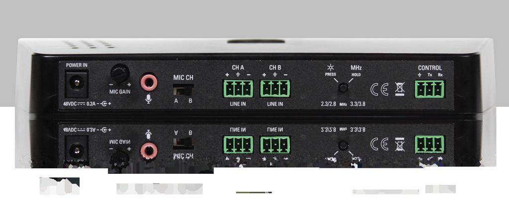
4 Figure 1: Receiver coverage area with IR T2 transmitter in single channel mode. IR T2 Coverage Pattern with RX22-4 Receiver Green Power The IR T2 is equipped with a sleep/power save feature. If no audio is present on either channel for twelve minutes, the transmitter will automatically go into sleep/power save mode. This mode decreases power consumption by 80 percent. Units will automatically start up when audio is activated. While operating, the IR T2 performs a self-test to detect damage due to shipping, handling, tampering or incorrect operation. If any failure is present, the power indicator light will blink rapidly. The unit will attempt to recover automatically by rebooting. See IR T2 Indicators table on page 11 for instructions on how to read indicator lights. 25 Connecting the Audio Source Automatic Channel Detection/ Shutdown The IR T2 offers two simultaneous carrier frequencies settings: Ch A (2.3 MHz) and Ch B (2.8 MHz) or Ch A (3.3 MHz) and Ch B (3.8 MHz). Control Panel Figure 2: IR T2 rear view The unit automatically detects the presence of audio on the microphone and Phoenix style audio inputs, and transmits on either/both channels when an audio signal is present on that channel. If audio is present on both the microphone and Phoenix style audio input for a given channel, the audio signals will be mixed. This setting may manually be adjusted by using the carrier selection button on the back of the device to toggle between 2.3/2.8 MHz or 3.3/3.8 MHz. MICROPHONE POWER ADJUSTMENT INDICATOR (GREEN) CH A AUDIO LEVEL INDICATOR (YELLOW) CH B AUDIO LEVEL INDICATOR (YELLOW) LED BACK PANEL LIGHTS ON/OFF (PRESS AN RELEASE) CHANGE CARRIER FREQUENCY (PRESS AND HOLD FOR 3 SECONDS) If no audio is detected on either channel when the IR T2 is turned on, the unit will immediately go into power save mode and shut off the IR. While operating, when no audio signal is present on a channel for twelve minutes, the IR T2 will shut down that channel. Operating the IR T2 in single-channel mode provides a 40 percent increase in range over two-channel mode. MIC IN MIC CHANNEL SELECTOR Connecting Power AUDIO LINE IN CARRIER INDICATOR LED (2.3,2.8) CARRIER INDICATOR LED (3.3,3.8) RS-232 CONTROL AND MONITORING BUS WARNING: MAINS VOLTAGE MUST NOT FALL BELOW 100 VAC, OR SYSTEM PERFORMANCE WILL BE GREATLY REDUCED. UNIT MAY ENTER RESET MODE UNTIL POWER IS RESTORED. Microphone Source (3.5 mm Mono Plug) Plug an electret microphone into the 3.5mm Mic In jack (MIC 027, MIC 100, or MIC 090). To assign the microphone to Ch A use the Mic Channel Selector to select Ch A. To assign the microphone to Ch B use the Mic Channel Selector to select Ch B. Line Level Source (Phoenix style connectors) The IR T2 will accept line level balanced or unbalanced audio inputs. Select the frequency you wish to transmit on and connect your audio source(s) to the appropriate Phoenix style connectors. No adjustment needs to be made for balanced or unbalanced inputs; this is internally detected & managed. See Figure 3 and Figure 4 for balanced and unbalanced cable configurations. 1. Plug the power supply output cord into Power In on the IR T2. 2. Attach a line cord to the power supply. 3. Plug the power supply into the AC outlet. TFP 057: VAC IN, 50 / 60 Hz. This system is designed for class 2, low-voltage wiring. Always follow local electrical codes when using low-voltage wiring. 6 7
5 Figure 3: Balanced line out (XLR) to IR T2 line input (Phoenix style connector) Figure 5: Summing an unbalanced stereo source to a single mono input FEMALE XLR RED (IN PHASE [+]) SHIELD BLACK (SIGNAL [-]) 1= SHIELD, 2= RED (SIGNAL IN PHASE), 3= BLACK (SIGNAL) 2 CONDUCTOR WITH SHIELD RED BLACK CONNECTED TO - SHIELD CONNECTED TO GND ON IR T2 CABLE END Figure 4: Unbalanced line out (XLR) to IR T2 line input (Phoenix style connector) FEMALE XLR RED (IN PHASE [+]) SHIELD BLACK (SIGNAL [-]) 1= SHIELD, 2= RED (SIGNAL IN PHASE), 3= BLACK (SIGNAL) 2 CONDUCTOR WITH SHIELD RED BLACK SHIELD NOT CONNECTED ON IR T2 CABLE END PHOENIX STYLE CONNECTOR 3-Pin, 0.15 Pitch + - PHOENIX STYLE CONNCTOR 3-Pin, 0.15 Pitch + - TO IR T2 TO IR T2 USE SHORT WIRE TO CONNECT - TO Summing an unbalanced stereo line-level source to a single mono input If using a stereo source for an input, the stereo signal will be combined to mono, and heard in mono, on the A or B channel of the IR T2. The + and - phoenix terminals on the IR T2 are each tied internally to single differential amplifiers. Proper Wiring (Yes circle in Figure 5): The resistors, along with the jumper between - and ground, are necessary to allow the left and right signals to be summed before being preamplified by the single differential (single-ended) amplifier inside the IR T2. Improper Wiring (No circle in Figure 5): If the left and right positive leads from the source were connected to the + and - pins on the Phoenix style connector, and their grounds (shields) were connected to the ground terminal, the result would be the difference of the left and right channels. The main part of the audio signal (what is common to both the left and right channels) would be missing, as this is thrown away during differential amplification. The difference is very little, resulting in a very low input signal. In this case, most of the original audio would not be heard! 3.5mm RCA POWER IN 48VDC 0.2A- C + - MIC GAIN + white white MIC CH A L+ L- shields red R- R+ L+ L- shield shield R- red R+ Adjusting the Audio Level B CH A CH B L+ LINE IN 1kΩ 1/16 Watt Resistors IR T2 R+ LINE IN L- Yes PRESS MHz HOLD 2.3/2.8 MHz 3.3/3.8 Use short wire to connect - to (shields) R- CONTROL Tx Rx L+ R+ L- R- No (shields) Line Level Source After an audio signal has been connected to the transmitter, adjust the audio source gain until the IR T2 audio-level indicator for that channel blinks periodically. Microphone Source Speak into the microphone from a normal distance and at a natural voice level. Use the microphone gain adjustment on the IR T2 to set the gain to the point where the audio level indicator on the selected channel blinks periodically. If the audio level indicator is always on or is on most of the time, the level is too high. If the audio level indicator is never on, the level is too low. Remote Control and Monitoring RS-232 Cable Wiring If a third-party controller (Crestron, AMX, Extron, etc.) is desired, the IR T2 has RS-232 control and monitoring available. Figure 6 shows how to make a custom RS-232 control cable if the third party controller has a DB-9 connector. The only pins required are 2, 3 and 5. Pins 2 and 3 are reversed from one end to the other: the receive on the DB-9 is connected to transmit on the Phoenix style connector, and transmit on the DB-9 is connected to receive on Phoenix style connector. This circuit facilitates 2-way communication between the third-party controller (Crestron, AMX, Extron, etc.) and the IR T2. If the third-party controller also has a Phoenix style connector (not a DB-9 connector), follow the same convention where the TX and RX pins are reversed from one end to the other. See the IR T2 Programmers Guide for additional information. 8 9
6 Figure 6: RS-232 Standard Cable Pinout Configuration Troubleshooting DATA CARRIER DETECT DATA SET READY RECEIVE DATA REQUEST TO SEND TRANSMIT DATA CLEAR TO SEND DATA TERMINAL READY RING INDICATOR SIGNAL GROUND CHASSIS GROUND DB-9 CONNECTOR PHOENIX TX RX MAX cable length varies based on cable quality and 3rd party connected device, but with low capacitance cable (such as CAT5e or CAT6), cable lengths greater than 100ft are achievable. For easier troubleshooting, the IR T2 units are equipped with a series of self-tests and indications. Please see IR T2 indicator lights table on page 11 to aid in troubleshooting. TO IR T2 The IR T2 s Power Indicator is not lit: Make sure the power supply is plugged into the transmitter and any remote power switch is on. Press the LED on/off switch on the back panel to make sure the LEDs are enabled. The green power LED and the carrier indicator LED should light. Make sure the electrical outlet is on. Make sure the 48 VDC power supply is working. The IR T2 s Ch A or Ch B Audio-level Indicator does not light: Make sure the IR T2 is plugged in. Press the LED on/off switch on the back panel to make sure the LEDs are enabled. The green power LED and the carrier indicator LED should light. Make sure the audio input is connected properly. Refer to Figure 3 or Figure 4 depending on the connection being used. Make sure an active and adequate level audio signal is being sent to the IR T2 transmitter. No Sound through Receivers: Check to make sure the receiver is operating on the same frequency as the transmitter. Make sure the front of the receiver is facing the transmitter. If some of the receivers work but others don t, check for bad batteries or earphones. If none of the receivers work, check to see if the power and audio input cables are connected to the transmitter. Verify that the Power Indicator is on steady, and Ch A or Ch B audio-level indicator blinks periodically. Check to see if the transmitter is connected properly to the audio source. If the indicators are enabled, the audio-level indicators should flash on channels that have audio. Make certain the transmitter is not covered by objects which would block infrared light. Sound Through the Receivers is Weak and Noisy: Try adjusting the audio input level (see page 9). If the signal sounds okay, you may need to reposition the transmitter beam. Buzzing or Humming Noise in Sound System: Check for ground loops or noise on the input signal. Reference Figure 5 for more details. If these instructions do not address your problem or the issue persists, please call your authorized Williams Sound dealer or representative. You may also reach our TechBlue team by calling and asking for TechBlue. IR T2 Indicator lights INDICATOR STATE DESCRIPTION On steady Unit is powered and actively transmitting Power Indicator Fade-on, Fade-off (continuous) Green (round) Audio Level Indicators Yellow (round) (Ch A or Ch B) All indicators Fast blink (continuous) Blinking periodically On steady (or most of the time) Off On for 2 seconds, Off for 1 second, resumes normal states On for 2 seconds, Off for 1 second (continuous) Unit is powered and in sleep/power-save mode (no audio signal detected, unit is not transmitting) Self test has detected a failure on this unit and will attempt recovery by rebooting. Audio is present on this channel and is set to the optimum level Audio is present on this channel, but the level is too high Audio is not present OR audio level is too low on this channel Initial power-on sequence OR unit has reset Unit is continuously resetting - may be due to a low voltage supply condition (possibly caused by bad power supply, improper user connection or signal level) NOTE: The indicator lights can all be turned off AFTER initial set-up to allow for less conspicuous operation. Press and release the LED on/off button on the back of the device. Mounting Options BKT Universal wall / ceiling mount (included) MLB Linking bar for stacking transmitters STD Tabletop tripod stand The IR T2 can be mounted on any camera tripod stands with a 1/4-20 threaded connector. Do not paint the front of the IR T2. Accessories MIC Hand-held unidirectional microphone MIC Lavaliere microphone MIC Rear-wear headset microphone WCA RCA to Phoenix cable Optional Receivers WIR RX22-4 Receiver: (4-channel receiver: Channel 1=2.3 MHz, channel 2=2.8 MHz, channel 3=3.3 MHz, and channel 4=3.8 MHz). WIR RX18 Receiver EARPHONE JACK "ON" INDICATOR CHANNEL SELECTOR OFF ON/OFF VOLUME SWITCH FREQUENCY SELECTION SWITCH 2.3 MHz, STEREO, 2.8 MHz VOLUME CONTROL BALANCE CONTROL BATTERY (BAT AP07D)
7 Infrared Transmitter Specifications Model IR T2 Dimensions, Weight: Color: 9.0" W (229 mm) x 3.8" D (97 mm) x 1.4" H (36 mm), 0.84 lb. (0.38 kg) Black Power Supply: TFP 057 Desktop style international certified power supply with IEC line cord, VAC input, Hz, 18 W; 48 VDC output DC Power Input: Power Indicator: Sleep/Power Save Mode: Modulation: Emitter IR Power: Transmit Frequencies: Transmit Channel: Coverage Area: Microphone input: Microphone gain adjust: Microphone channel switch: Audio Inputs / Controls: Audio indicators: Indicators On/Off: Frequency Selection: Signal-to-Noise Ratio: Frequency Response: Total Harmonic Distortion: Control/Monitoring: Operating Requirements: Mounting Kit: Warranty: Approvals: Compatible Receivers: 2.1 mm ID barrel connector, 48 VDC, 0.2A, center positive Green LED Shuts off carrier when no audio is present for 12 minutes FM Wideband, ±50 khz deviation max, 50 μs pre-emphasis 0.7 W 2.3, 2.8, 3.3, 3.8 MHz Indicators: Yellow LEDs indicate whether 2.3/2.8 MHz or 3.3./3.8 MHz transmission frequencies are selected Up to 18,000 sq. ft (1,673 sq. m) in single-channel mode with the RX22-4 receiver 3.5 mm, stereo jack with signal and bias connected to tip, electret microphone compatible (6 VDC bias supply with 2.7 k ohm series resistor) Rotary 10 db range Selects microphone input to Ch. A or Ch. B Line inputs: Phoenix style connector jack for Ch A and Ch B accept line level, balanced or unbalanced audio Yellow LED blinks at nominal audio level. One per channel Momentary contact switch turns on/off indicator lights Press and hold momentary contact switch to change carrier frequency group. 70 db (line input) 95 Hz to 17.6 khz, -3 db re 1 khz (line inputs) 125 Hz to 17.0 KHz, -3 db re 1 khz (microphone input) <1% (1 khz, nominal deviation, line or microphone input) 3-wire RS-232 bus, standard ASCII commands/replies, Baud rate (8N1). See the IR T2 Programmers Guide for more information F (0-50 C) Wall or Ceiling mount: BKT 024 Omnidirectional mount 5 Years CE, FCC, Industry Canada, WEEE, RoHS, CB Scheme, RCM, PSE WIR RX22-4, WIR RX18, IR R1 Limited Warranty Williams Sound products are engineered, designed, and manufactured under carefully controlled conditions to provide many years of reliable service. Williams Sound warrants the IR T2 infrared listening system against defects in materials and workmanship for five (5) years. During the first five years from the purchase date, we will promptly repair or replace the IR T2 infrared listening system. Microphones, earphones, headphones, batteries, chargers, cables, carry cases, and all other accessory products carry a 90-day warranty. WILLIAMS SOUND HAS NO CONTROL OVER THE CONDITIONS UNDER WHICH THIS PRODUCT IS USED. WILLIAMS SOUND, THEREFORE, DISCLAIMS ALL WARRANTIES NOT SET FORTH ABOVE, BOTH EXPRESS AND IMPLIED, WITH RESPECT TO THE IR T2 INFRARED LISTENING SYSTEM, INCLUDING BUT NOT LIMITED TO, ANY IMPLIED WARRANTY OF MERCHANTABILITY OR FITNESS FOR A PARTICULAR PURPOSE. WILLIAMS SOUND SHALL NOT BE LIABLE TO ANY PERSON OR ENTITY FOR ANY MEDICAL EXPENSES OR ANY DIRECT, INCIDENTAL OR CONSEQUENTIAL DAMAGES CAUSED BY ANY USE, DEFECT, FAILURE OR MALFUNCTIONING OF THE PRODUCT, WHETHER A CLAIM FOR SUCH DAMAGES IS BASED UPON WARRANTY, CONTRACT, TORT OR OTHERWISE, THE SOLE REMEDY FOR ANY DEFECT, FAILURE OR MALFUNCTION OF THE PRODUCTS REPLACEMENT OF THE PRODUCT. NO PERSON HAS ANY AUTHORITY TO BIND WILLIAMS SOUND TO ANY REPRESENTATION OR WARRANTY WITH RESPECT TO THE IR T2 INFRARED LISTENING SYSTEM. UNAUTHORIZED REPAIRS OR MODIFICATIONS WILL VOID THE WARRANTY. The exclusions and limitations set out above are not intended to, and should not be construed so as to contravene mandatory provisions of applicable law. If any part or term of this Disclaimer of Warranty is held to be illegal, unenforceable, or in conflict with applicable law by a court of competent jurisdiction, the validity of the remaining portions of this Disclaimer of Warranty shall not be affected, and all rights and obligations shall be construed and enforced as if this Limited Warranty did not contain the particular part or term held to be invalid. If you experience difficulty with your system, call toll-free for customer assistance: (U.S.A.) or (outside the U.S.A.) If it is necessary to return the system for service, your Customer Service Representative will give you a Return Authorization Number (RA) and shipping instructions. Pack the system carefully and send it to: Williams Sound Attn: Repair Dept Valley View Road Eden Prairie, MN USA NOTE: Specifications subject to change without notice. Visit our website for the latest specifications and publications: Your warranty becomes effective the date you purchase your system. If your sales receipt is not available, the date code on the product will determine your warranty status
8 This page is intentionally left blank. This page is intentionally left blank
9 / / INTL: , Williams AV, LLC MAN 217A
DL102 Counter Loop Amplifier
 DL102 Counter Loop Amplifier USER MANUAL MAN 234A Contents Overview...3 System Includes...3 Maintenance and Recycling Instructions...3 Safety Information...4 Quick Setup...5 Setup...6 Loop Amplifier...6
WIR TX75 PRO Infrared Transmitter 2.3,2.8 / 3.3,3.8 MHz
 WIR TX75 PRO Infrared Transmitter 2.3,2.8 / 3.3,3.8 MHz USER Manual MAN 166E WIR TX75c, WIR TX75d PRO Infrared Transmitters Contents Important Safety Instructions...3 CAT-5e Cable Safety...3 Receiver Safety
Manual and User Guide
 Manual and User Guide TV Talker FM System Model WFM 260 Model WFM 270 Transmitter Model WFM TX260 Receiver Model WFM RX260 Receiver Model WFM RX270 MAN 151H 2011 Williams Sound, LLC Contents Page System
Installation Guide & User Manual
 Installation Guide & User Manual SoundPlus Infrared Listening System Model WIR TX90, Two Channel System Model WIR SYS 90 ADV, Two Channel System Model WIR SYS 91V, Two Channel System Transmitter Model
CAUTION! CAUTION! Hearing Helper Transmitter, Model PFM T32 Instructions For Use and Care
 Hearing Helper Transmitter, Model PFM T32 Instructions For Use and Care Thank you for purchasing the PFM T32 transmitter from Williams Sound. The T32 is designed to operate with a wideband FM, 72 76 MHz
Hearing Helper. Wireless FM Listening System. Manual and User Guide. Transmitter Model T800 Optional Receiver Model R863 MAN 143C
 Hearing Helper Wireless FM Listening System Manual and User Guide Transmitter Model T800 Optional Receiver Model R863 Hearing Helper T800 Transmitter Manual and User Guide Contents System Overview... 3
DA216S DISTRIBUTION AMPLIFIER
 DISTRIBUTION AMPLIFIER IMPORTANT SAFETY INSTRUCTIONS 1. Read these instructions. 2. Keep these instructions. 3. Heed all warnings. 4. Follow all instructions. 5. Do not use this apparatus near water. 6.
Installation Guide & User Manual
 Installation Guide & User Manual SoundPlus Infrared Listening System Model WIR TX925, Two-Channel Listening System Model WIR TX900, Four-Channel Listening System Model WIR SYS 1, Two-Channel Listening
WIR TX925, WIR SYS 1 Two-Channel Infrared Listening Systems
 WIR TX925, WIR SYS 1 Two-Channel Infrared Listening Systems User Manual Emitter Model WIR TX9 DC Modulator Model MOD 232 Optional Receiver Models WIR RX18, WIR RX22-4 WIR TX9 DC EMITTER MOD 232 MODULATOR
WIR TX90. SoundPlus Infrared Transmitter INFRARED SPECIFICATION DATA
 INFRARED SPECIFICATION DATA Cinemas Simultaneous Interpretation Audio Description Conferences Multi-Media Rooms Boardrooms Courtrooms Schools Universities Churches WIR TX90 SoundPlus Infrared Transmitter
WIR TX90. SoundPlus Infrared Transmitter INFRARED SPECIFICATION DATA
 INFRARED SPECIFICATION DATA Cinemas Simultaneous Interpretation Audio Description Conferences Multi-Media Rooms Boardrooms Courtrooms Schools Universities Churches WIR TX90 SoundPlus Infrared Transmitter
INSTALLATION MANUAL ECA-70VMINI-60W ECA-70VMINI-60W L VOLUME SPEAKER OUTPUTS 12VDC IN + L+ L- GND R+ R- S GND GND Tx Rx
 INSTALLATION MANUAL ECA-70VMINI-60W ECA-70VMINI-60W L VOLUME R 12VDC IN BALANCED IN STEREO IN UNBALANCED IN SERVICE STATUS IR RS-232 + L+ L- GND R+ R- S GND GND Tx Rx SPEAKER OUTPUTS + page 2 CAUTION Risk
Hearing Helper T800 Transmitter Wireless FM Listening System
 Manual and User Guide Hearing Helper T800 Transmitter Wireless FM Listening System Transmitter Model T800 Optional Receiver Model R863 MAN XXX 2008 Williams Sound Corp. Hearing Helper T800 Tr a n s m i
A-16D A-Net Distributor
 A-16D A-Net Distributor For use with the Personal Monitor Mixing System Information in this document is subject to change. All rights reserved. Copyright 2003 Aviom, Inc. Printed in USA Document Rev. 1.03
XD-V30 Digital Wireless System
 XD-V30 Digital Wireless System Pilot s Handbook Manuel de pilotage Pilotenhandbuch Pilotenhandboek Manual del Piloto 取扱説明書 See www.line6.com/manuals for Advance Guide 40-00-0286 Advanced Users Guide available
WIR SYS 3. SoundPlus Value Courtroom System ADA Courtroom Assistive Listening System INFRARED SPECIFICATION DATA
 INFRARED SPECIFICATION DATA Courtrooms Military Installations Embassies Consulates Political Offices WIR SYS 3 SoundPlus Value Courtroom System ADA Courtroom Assistive Listening System The Value Courtroom
plifier D-501 otion Am Tactile M
 Tactile Motion Amplifier D-501 IMPORTANT SAFETY INSTRUCTIONS WARNING: 1. Read and keep these instructions for future reference. 2. Do not use this apparatus near water. 3. Clean only with a dry cloth.
User Guide. Radio with Universal ipod Dock NS-B3113B
 User Guide Radio with Universal ipod Dock NS-B3113B Contents Insignia NS-B3113B Radio with Universal ipod Dock Introduction.....................................................3 Safety information...............................................
HTA125A/250A. Power Amplifiers. Installation & Use Manual
 HTA125A/250A Power Amplifiers Installation & Use Manual Specifications subject to change without notice. 2010 Bogen Communications, Inc. All rights reserved. 54-5832-04B 1011 NOTICE: Every effort was made
SPECIAL 6. 6-Watt Vacuum Tube Guitar Amplifier. User Manual
 SPECIAL 6 6-Watt Vacuum Tube Guitar Amplifier User Manual Table of Contents Table of Contents... 3 Product Safety Information...4 Panel Functions... 5 Technical Specifications... 8 Important Safety Instructions
M-300 Mono power amplifier User s guide
 M-300 Mono power amplifier User s guide M-300 Mono power amplifier User s guide Specifications: Contents: Power output: 8Ω: 290W, 0.01% THD SPECIFICATIONS Page 2 Input impedance: Gain: 4Ω: 580W, 0.01%
Classic Series Public Address Amplifiers C10 & C20 Models
 Classic Series Public Address Amplifiers C10 & C20 Models Installation and Use Manual 2009 Bogen Communications, Inc. All rights reserved. Specifications subject to change without notice. 54-5978-01C 1106
PREMIUMAUDIOVIDEOLIGHTINGANDPOWERPRODUCTS
 FACTOR ELECTRONICS PREMIUMAUDIOVIDEOLIGHTINGANDPOWERPRODUCTS VT-1 / VT-4 Professional Tuners With RBDS Owners Manual Owners Manual IMPORTANT NOTE: THIS OWNER'S MANUAL IS PROVIDED AS AN INSTALLATION AND
Classic Series Public Address Amplifiers C10 & C20 Models
 Classic Series Public Address Amplifiers C10 & C20 Models Installation and Use Manual 2009 Bogen Communications, Inc. All rights reserved. Specifications subject to change without notice. 54-5978-01B 0901
Model CC4041. CC Series Amplifier. Installation and Use Manual
 BASS 0 TREBLE 0-12 +12-12 +12 INPUT 1 INPUT 2 INPUT 3 INPUT 4 PEAK SIGNAL POWER POWER CC Series Amplifier Model CC4041 Installation and Use Manual 2012 Bogen Communications, Inc. All rights reserved. Specifications
ECA COMMERCIAL AMPLIFIER OWNER S MANUAL ECA-70MIXAMP V / 70V / 4Ω Amplifier ECA-70MIXAMP-1-60 OUTPUT LEVEL POWER MASTER MIC 1
 OWNER S MANUAL ECA COMMERCIAL AMPLIFIER ECA-MIXAMP--6 V / V / Ω Amplifier TEMP PROT OUTPUT LEVEL ECA-MIXAMP--6 6 POWER MIC MIC MIC MIC AUX AUX BASS TREBLE 5 5 5 5 5 6 6 6 6 6 MASTER 5 6 ON OFF + - + -
A Channel Amplifier
 Installation Manual A2150 2 Channel Amplifier Table of Contents Installation Requirements and Recommendations 1 What s included 1 Speaker Wire Recommendations 1 Setup 2 Rack Mounting 2 Individually Protected
Classic Series Amplifiers C35, C60, & C100 Models
 Classic Series Amplifiers C35, C60, & C100 Models Installation and Use Manual 2009 Bogen Communications, Inc. All rights reserved. Specifications subject to change without notice. 54-5979-02E 1203 Notice:
Installation Guide & User Manual Sound Plus Infrared System, Model WIR 950
 Installation Guide & User Manual Sound Plus Infrared System, Model WIR 950 Sound Plus Williams Sound MAN 101B 1 OVERVIEW Thank you for purchasing the WIR 950 Infrared System from Williams Sound Corp. Anyone
Model CC4052. CC Series Amplifier. Installation and Use Manual
 CC Series Amplifier Model CC4052 Installation and Use Manual 2012 Bogen Communications, Inc. All rights reserved. Specifications subject to change without notice. 54-2216-01A 1303 NOTICE: Every effort
2BSST POWER AMPLIFIER OWNER S MANUAL
 2BSST POWER AMPLIFIER OWNER S MANUAL IMPORTANT SAFETY INSTRUCTIONS The lightning flash with arrowhead symbol within an equilateral triangle, is intended to alert the user to the presence of un-insulated
NS-HDTUNE HD Radio Tuner
 NS-HDTUNE HD Radio Tuner HD Radio Tuner Contents Insignia NS-HDTUNE HD Radio Tuner Introduction.................................... 3 Safety information.............................. 4 Features........................................
11. ONLY USE attachments/accessories specified by the manufacturer.
 U H F Table of Contents System Components...1 Functions of the ECDR Receiver...2 HH38 Handheld Transmitter...3 MBP38 Bodypack Transmitter...4 Tips for Improving System Performance...5 Frequency...6 Specifications...7!
Important Safety Information
 OWNER'S MANUAL Important Safety Information 1. Read these instructions. 2. Keep these instructions. 3. Heed all warnings. 4. Follow all instructions. 5. Do not use this apparatus near water. 6. Clean only
AV30MX-2 Operation Manual
 AV30MX-2 Operation Manual 1 Important safety instructions 1. Please read carefully prior to product installation or operation. 2. Read these instructions. 3. Keep these instructions. 4. Heed all warnings.
MANUAL AND USER GUIDE
 MANUAL AND USER GUIDE Whisper Tour Guide System Wireless, Portable FM Listening System Model TGS 863 Transmitter Model T863 Receiver Model R863 MAN 130B 2007 Williams Sound Corp. WHISPER FM TOUR GUIDE
PPA 377. Personal PA FM Listening System FM SPECIFICATION DATA. System Includes:
 FM SPECIFICATION DATA Churches Schools Auditoriums Conference Rooms Theaters PPA 377 Personal PA FM Listening System The PPA 377 features the T35 high performance transmitter: powerful microprocessor,
Copyright 2017, Samson Technologies Corp. v1.1. Samson Technologies Corp. 278-B Duffy Ave Hicksville, NY
 OWNER'S MANUAL Copyright 2017, Samson Technologies Corp. v1.1 Samson Technologies Corp. 278-B Duffy Ave Hicksville, NY 11801 www.samsontech.com Important Safety Information ATTENTION RISQUE DE CHOC ÉLECTRONIQUE
WX-1 & WX-3 OPERATING MANUAL AND USER GUIDE. Professional Power Amplifier. WX-1 and WX-3.indd :23:16
 WX-1 & WX-3 Professional Power Amplifier OPERATING MANUAL AND USER GUIDE 3 www.wharfedalepro.com WX-1 and WX-3.indd 1 2014-7-16 10:23:16 TABLE OF CONTENTS TABLE OF CONTENTS... 1 IMPORTANT WARNINGS & SAFETY
IMPORTANT SAFETY INSTRUCTIONS
 Addendum IMPORTANT SAFETY INSTRUCTIONS Read these instructions. Keep these instructions. Heed all warnings. Follow all instructions. Do not use this apparatus near water. Mains powered apparatus shall
Lanen True Diversity UHF Systems For electric and bass guitars: GB21 For Series 21 mics: UHF21. User Manual GB21 receiver/uhf21 transmitter
 Lanen True Diversity UHF Systems For electric and bass guitars: GB21 For Series 21 mics: UHF21 User Manual GB21 receiver/uhf21 transmitter Safety Information Thank you for purchasing this digital appliance.
manual & user guide Wireless FM Listening System
 manual & user guide Wireless FM Listening System Models PFM 360, PFM 330, PFM 360 RCH & PFM 330 RCH Transmitter Model PFM T36 Optional Receiver Models PFM R36, R33 MAN 146B ... Motiva Personal FM System
EPA152/252/502. User Manual.
 EPA152/252/502 User Manual www.audac.eu ADDITIONAL INFORMATION This manual is put together with much care, and is as complete as could be on the publication date. However, updates on the specifications,
Important safety instructions
 MMR-88 Version 1 Important safety instructions 1. 2. 3. 4. 5. 6. 7. 8. 9. Please read these instructions carefully. Please keep these instructions for future reference. Heed all warnings Follow all instructions
FOR AVLEX ONLY MT-24A. User Guide. 2.4 GHz Digital Stationary Transmitter
 2.4 GHz Digital Stationary Transmitter User Guide All rights reserved. MN 017/05 Do not copy or forward without prior approvals MIPRO. Specifications and design subject to change without notice. 2 CE5
IMPORTANT SAFETY INSTRUCTIONS
 WR-1 Version 1 IMPORTANT SAFETY INSTRUCTIONS 1. 2. 3. 4. 5. 6. 7. 8. 9. Read these instructions. Keep these instructions. Heed all warnings. Follow all instructions. Do not use this apparatus near water.
AV25-2 User Manual. 1 Important safety instructions
 AV25-2 User Manual 1 Important safety instructions 1. Please read carefully prior to product installation or operation. 2. Read these instructions. 3. Keep these instructions. 4. Heed all warnings. 5.
SoundPlus Infrared System Model WIR SYS 90 ADV
 escription: The 0 two channel IR transmitter combines modulator and emitter technology into a single operating unit, which reduces operating cost and eliminates precious rack space. The 0 transmitter advduces
MIC MECHANIC 2. Ultra-Simple Battery-Powered Vocal Effects Stompbox with Echo, Reverb and Pitch Correction. User Manual
 MIC MECHANIC 2 Ultra-Simple Battery-Powered Vocal Effects Stompbox with Echo, Reverb and Pitch Correction User Manual 2 MIC MECHANIC 2 User Manual Important Safety Instructions Terminals marked with this
AUDIOLINK PRO. Warranty Conditions INSTRUCTION MANUAL M110 INFRARED TRANSMITTER
 AudioLink PRO M110 Warranty Conditions ELT Corp. warrants that this AudioLink PRO product is free from defects in material and workmanship for the period of two years from the date of purchase. If this
IMPORTANT SAFETY INSTRUCTIONS
 WR-11 Version 1 IMPORTANT SAFETY INSTRUCTIONS 1. Read these instructions. 2. Keep these instructions. 3. Heed all warnings. 4. Follow all instructions. 5. Do not use this apparatus near water. 6. Clean
Big Bang. B B O w n e r s M a n u a l. Power Amplifiers. SpeakerCraft BB2125 POWER ACTIVE PROTECTION L
 Big Bang Power Amplifiers SpeakerCraft BB2125 ACTIVE POWER PROTECTION L R B B 2 1 2 5 O w n e r s M a n u a l SAFETY INSTRUCTIONS APPLICABLE FOR USA, CANADA OR WHERE APPROVED FOR USAGE CAUTION: To reduce
AM/FM SYNTHESIZER TUNER DT-920. TOA Corporation OPERATING INSTRUCTIONS
 OPERATING INSTRUCTIONS AM/FM SYNTHESIZER TUNER DT-920 Please follow the instructions in this manual to obtain the optimum results from this unit. We also recommend that you keep this manual handy for future
HARMONY SINGER 2. Battery-Powered Vocal Effects Stompbox with Guitar-Controlled Harmony, Reverb and Tone. User Manual
 HARMONY SINGER 2 Battery-Powered Vocal Effects Stompbox with Guitar-Controlled Harmony, Reverb and Tone User Manual 2 Harmony Singer 2 User Manual Important Safety Instructions Terminals marked with this
MLM82S MIC / LINE MIXER
 MLMS MIC / LINE MIXER IMPORTNT SFETY INSTRUCTIONS. Read these instructions.. Keep these instructions. 3. Heed all warnings.. Follow all instructions. 5. Do not use this apparatus near water.. Clean only
1695T Black Magick. User Manual
 1695T Black Magick User Manual All contents c Absara Audio LLC 2014 1. Important Safety Information The triangle surrounding an exclamation mark alerts users to the presence of important warnings or information.
REVAMP4100 Instruction manual
 REVAMP4100 Instruction manual REVAMP4100 Instruction manual 3 REVAMP4100 manual 4 CLASS-D POWER AMPLIFIER IMPORTANT SAFETY INSTRUCTIONS 1. Read these instructions 2. Keep these instructions 3. Heed all
INSTRUCTION MANUAL LCS TX
 INSTRUCTION MANUAL LCS TX 4 Channel Transmitter LCS1 Single Channel Transmitter Cardio Theater Inc Service 1-800-776-6695 Sales 1-800-CARDIO-1 1 Introduction CONGRATULATIONS on your choice of this product
DPA-1.2. Instruction Manual. 2 Channel Amplifier with Auto A/B Selector DPA-1.2 DPA-1.2 POWER SERIAL # LINE INPUT SENSING SPEAKER B OUT
 POWER Russound DPA-1.2 Instruction Manual 2 Channel Amplifier with Auto A/B Selector NEWMARKET, NH USA DPA-1.2 Russound 68835 Conforms to UL 6500 Certified to CSA C22.2 No1-94 DPA-1.2 Tested to Comply
Courtrooms Schools Universities Cinema Churches
 SoundPlus W TX925 Infrared System Description: The W TX925 is ideal for language interpretation for up to two languages. It can operate up to 18, sq. ft. in two channel mode or 28, in single channel mode.
3400 Watt Stereo Power Amplifier
 3400 Watt Stereo Power Amplifier OWNER'S MANUAL Copyright 2014, Samson Technologies Corp. v1.1 Samson Technologies Corp. 45 Gilpin Ave Hauppauge, NY 11788 www.samsontech.com Important Safety Information
PREZONE1 Instruction manual
 PREZONE1 Instruction manual PREZONE1 manual PREZONE1 Instruction manual 3 4 Preamplifiers IMPORTANT SAFETY INSTRUCTIONS Read these instructions - All the safety and operating instructions should be read
PLA-240. Small Room Loop Amplifier System. USER Manual MAN 211A
 PLA-240 Small Room Loop Amplifier System USER Manual MAN 211A Overview Thank you for purchasing the PLA 240 Small Room Loop Amplifier System. The PLA 240 Loop System provides a practical solution for hearing
Personal PA Tour Guide System
 Personal PA Tour Guide System Wireless, Portable FM Listening System Manual and User Guide Transmitter Model PPA T36 Optional Receiver Models PPA R37, PPA R35-8 TGS PRO 737 TGS PRO MULTI PERSONAL PA FM
Tabletop HD Radio Receiver
 USER GUIDE Tabletop HD Radio Receiver NS-HDRAD2 Before using your new product, please read these instructions to prevent any damage. Contents Introduction.....................................................2
Synthesized Base Station Transmitter
 BST-75 OPERATOR S MANUAL (72-76 MHz) Synthesized Base Station Transmitter 357 West 2700 South Salt Lake City, Utah 84115 Phone: (800) 496-3463 Fax: (801) 484-6906 www.comtek.com TABLE OF CONTENTS Introduction...
Always there to help you. Register your product and get support at AJ3400/37. Question? Contact Philips.
 Always there to help you Register your product and get support at www.philips.com/support Question? Contact Philips AJ3400/37 User manual Contents 1 Important 3 Safety 3 2 Your clock radio 4 What's in
i3speakers LX503 MK2 User Manual
 i3speakers LX503 MK2 User Manual Index Introduction 5 Precautions 6 Safety requirements 6 Caution servicing 7 EC Declaration of Conformity 7 Waste of Electrical and Electronic Equipment (WEEE) 7 Chapter
R-Series R235LS 2-Channel Power Amplifier with Local Source Switching
 R-Series R235LS 2-Channel Power Amplifier with Local Source Switching User s Manual On Off R235LS POWER A MPLIFIER IMPORTANT SAFEGUARDS WARNING TO REDUCE THE RISK OF FIRE OR ELECTRIC SHOCK, DO NOT EXPOSE
On-Line Cardio Theater Wireless Digital Transmitter Installation and Instruction Manual
 On-Line Cardio Theater Wireless Digital Transmitter Installation and Instruction Manual Full installation instructions accompany your Cardio Theater equipment order. This On-Line version of our Installation/Instruction
Always there to help you. Register your product and get support at AE2430. User manual
 Always there to help you Register your product and get support at www.philips.com/support AE2430 User manual Contents 1 Important 2 Safety 2 Notice 3 2 Your Portable Radio 5 Introduction 5 What s in the
User Manual LMS-325 Line Monitor Speaker
 User Manual LMS-325 Line Monitor Speaker 9350-7490-000 Rev E 10/2010 PROPRIETARY NOTICE The product information and design disclosed herein were originated by and are the property of Bosch Security Systems,
User Guide. Wideband 4-channel Auto Gain-Control Antenna Divider
 User Guide AD-708 Wideband 4-channel Auto Gain-Control Antenna Divider All rights reserved. Do not copy or forward without prior approvals MIPRO. Specifications and design subject to change without notice.
REVAMP4120T Instruction manual
 REVAMP4120T Instruction manual REVAMP4120T Instruction manual 3 REVAMP4120T manual 4 CLASS-D POWER AMPLIFIER IMPORTANT SAFETY INSTRUCTIONS 1. Read these instructions 2. Keep these instructions 3. Pay
Owner s Manual / Safety Instructions / Compliance Information A Boston P.O.P. Product Make it your own... Horizon Solo. An about-face in radio design
 Horizon Solo High Performance AM/FM Radio An about-face in radio design Owner s Manual / Safety Instructions / Compliance Information A Boston P.O.P. Product Make it your own... IMPORTANT SAFETY INSTRUCTIONS
XLS SERIES LOUD SPEAKERS
 XLS SERIES LOUD SPEAKERS User Manual CERWIN-VEGA S LIMITED WARRANTY WELCOME TO THE FAMILY! First off, you have great taste in loudspeakers. At Cerwin-Vega!, deep bass and great highs are a way of life.
CR31. Companion. Instruction Manual
 CR31 Companion Instruction Manual 910-244700-001 IMPORTANT SAFETY INSTRUCTION PLEASE READ CAREFULLY ALL THE FOLLOWING IMPORTANT SAFEGUARDS THAT ARE APPLICABLE TO YOUR EQUIPMENT 1. Read Instructions - All
CLASS D STEREO AMPLIFIER 60 WPC. Model: APA102 User Manual
 CLASS D STEREO AMPLIFIER 60 WPC Model: APA102 User Manual CAUTION RISK OF ELECTRICAL SHOCK DO NOT OPEN CAUTION: TO REDUCE THE RISK OF ELECTRIC SHOCK, DO NOT REMOVE THE COVER. NO USER SERVICABLE PARTS INSIDE.
EPA104/254. User Manual.
 EPA104/254 User Manual www.audac.eu ADDITIONAL INFORMATION This manual is put together with much care, and is as complete as could be on the publication date. However, updates on the specifications, functionality
Radio Remote(s) (Installation Manual)
 (Installation Manual)") Radio Remote(s) (Installation Manual) 87 Progress Avenue, Tyngsboro, MA 01879, USA Phone (978) 649-4ECU Fax (978) 649-8363 http://www.qtiusa.com Trademarks, Version, Printing, and Copyright Trademarks
Radio Remote(s) (Installation Manual) 87 Progress Avenue, Tyngsboro, MA 01879, USA Phone (978) 649-4ECU Fax (978) 649-8363 http://www.qtiusa.com Trademarks, Version, Printing, and Copyright Trademarks
SVS SoundPath Wireless Audio Adapter Owner s Manual
 SVS SoundPath Wireless Audio Adapter Owner s Manual SVS SoundPath Wireless Audio Adapter Thank you for choosing SVS! The SoundPath Wireless Audio Adapter reduces subwoofer cable clutter without sacrificing
S-V16P. 16 Channel Video and Power Rack Balun
 S-V16P 16 Channel Video and Power Rack Balun Table of Contents Overview... 4 Installation and Operation... 5 Troubleshooting and Frequenty Asked Questions... 7 Technical Specifications... 8 Warranty...
900MHz Digital Hybrid Wireless Outdoor Speakers
 4015004 900MHz Digital Hybrid Wireless Outdoor Speakers User s Manual This 900 MHz digital hybrid wireless speaker system uses the latest wireless technology that enables you to enjoy music and TV sound
IMPORTANT SAFETY INSTRUCTIONS
 Owner s Manual IMPORTANT SAFETY INSTRUCTIONS WARNING FOR YOUR PROTECTION READ THE FOLLOWING: KEEP THESE INSTRUCTIONS HEED ALL WARNINGS The symbols shown above are internationally accepted symbols that
32 CHANNEL SELECTABLE CH MHZ DOWN VOLUME
 KARAOKE Professional UHF Wireless Microphone System VM-92U Operating Instructions UHF Frequency 64 Selectable Better Music Builder UHF MIC WIRELESS SYSTEM VM-92U 32 CHANNEL SELECTABLE 248 13.10 CH MHZ
Always there to help you. Register your product and get support at AJ5305D_12. Question? Contact Philips.
 Always there to help you Register your product and get support at www.philips.com/welcome Question? Contact Philips AJ5305D_12 User manual Contents 1 Important 3 Safety 3 2 Your Docking Entertainment System
THANK YOU! Crush Micro PiX. Thank you for choosing Orange. You are now a member of the Legendary British Guitar Amplifier owners club!
 THANK YOU! Thank you for choosing Orange. You are now a member of the Legendary British Guitar Amplifier owners club! Since 1968 when the company was founded, Orange has been a pioneering force in the
Tuner OWNER S MANUAL MODE D EMPLOI MANUAL DE INSTRUCCIONES
 UA Tuner OWNER S MANUAL MODE D EMPLOI MANUAL DE INSTRUCCIONES IMPORTANT SAFETY INSTRUCTIONS IMPORTANT SAFETY INSTRUCTIONS CAUTION RISK OF ELECTRIC SHOCK DO NOT OPEN CAUTION: TO REDUCE THE RISK OF ELECTRIC
AG30 USER S MANUAL.
 AG30 USER S MANUAL 30 WATT acoustic performance AMP FCC Statements 1. Caution: Changes or modifications to this unit not expressly approved by the party responsible for compliance could void the user s
Always there to help you. Register your product and get support at AJB4300. Question? Contact Philips.
 Always there to help you Register your product and get support at www.philips.com/support Question? Contact Philips AJB4300 User manual Contents 1 Important 2 Safety 2 2 Your FM/DAB+ clock radio 3 Introduction
EQ-AMP60 60W Mixer Amplifier
 EQ-AMP60 60W Mixer Amplifier Instruction Manual 4091 AMTC Center Drive Clearwater, FL 33764-6976 (727)531-3105 (727)531-3965 www.amtc.com Features 1. MIC 1 input with front- and rear-panel connectors 2.
Copyright 2018, Samson Technologies Corp. v1. Samson Technologies Corp. 278-B Duffy Ave Hicksville, NY
 OWNER'S MANUAL Copyright 2018, Samson Technologies Corp. v1 Samson Technologies Corp. 278-B Duffy Ave Hicksville, NY 11801 www.samsontech.com Important Safety Information ATTENTION RISQUE DE CHOC ÉLECTRONIQUE
E-800 power amplifier. user manual
 E-800 power amplifier user manual Musikhaus Thomann Thomann GmbH Hans-Thomann-Straße 1 96138 Burgebrach Germany Telephone: +49 (0) 9546 9223-0 E-mail: info@thomann.de Internet: www.thomann.de 20.05.2016,
Black Oak / Light Oak / Cherrywood Wireless Panel Speaker
 4015115/4015116/4015117 Black Oak / Light Oak / Cherrywood Wireless Panel Speaker With Infrared Remote Control USER GUIDE For use with: Introduction These 900 MHz stereo wireless speaker system uses the
Always there to help you. Register your product and get support at AJ3400/79. Question? Contact Philips.
 Always there to help you Register your product and get support at www.philips.com/support Question? Contact Philips AJ3400/79 User manual Contents 1 Important 3 2 Your clock radio 4 What's in the box 4
INSTALLATION GUIDE. Video Balun Transceiver with fixed BNC for twisted pair operation with other balun transceivers or active receivers.
 INSTALLATION GUIDE VB37M Video Balun Transceiver for Twisted Pair Description Video Balun Transceiver with fixed BNC for twisted pair operation with other balun transceivers or active receivers. The VB37M
Carmen Ghia. Manual. Model: ZA-07.
 Carmen Ghia Manual Model: ZA-07 www.drzamps.com This symbol warns the user of dangerous voltage levels localized within the enclosure. This symbol advises the user to read all accompanying literature for
A W Table-Top Amplifier. with Built-in Bluetooth streaming
 A0361 100W Table-Top Amplifier with Built-in Bluetooth streaming 17 The A0361 Table-Top Amplifier can be used with Channel Vision s CAT5 audio hubs to provide a powerful 100 Watt Amplifier, 50Watts per
XPR522 XPR540. XPR SERIES INSTALLATION / OWNER'S MANUAL Mobile Power Amplifiers
 XPR522 XPR540 XPR SERIES INSTALLATION / OWNER'S MANUAL Mobile Power Amplifiers Preparation Please read entire manual before installation. Due to the technical nature of amplifiers, it is highly recommended
AG60 USER S MANUAL.
 AG60 USER S MANUAL 60 WATT acoustic PERFORMANCE SYSTEM FCC Statements 1. Caution: Changes or modifications to this unit not expressly approved by the party responsible for compliance could void the user