Triarchy VSG6G1C USB Vector RF Signal Generator Operating Manual
|
|
|
- Elijah Webb
- 5 years ago
- Views:
Transcription


1 Triarchy VSG6G1C USB Vector RF Signal Generator Operating Manual CW signal NB RF noise generator Analog modulation GMSK modulation Frequency sweeping Hopping with data Mod Page 1 of 27 8PSK GSM signal Pulse modulation 4FSK
2 USB Vector RF Spectrum Analyzer Operating Manual Copyright Notice Copyright 2018 Triarchy Technologies, Corp. All rights reserved. Initial Version December 2018 Documentation version 1.0 No part of this publication may be reproduced, transmitted, transcribed, stored in a retrieval system, or translated into any language or computer language, in any form or by any means, electronic, mechanical, magnetic, optical, chemical, manual, or otherwise, without the prior written permission of Triarchy Technologies, Corp. Technical Support For technical support, please call 1-, send to info@triachytech.com, or visit our website at Page 2 of 27
3 Contents 1 Introduction 1.1 VSG6G1C Product Package Overview 1.2 USB Device Overview 1.3 TSG PC Application Overview 1.4 Electrical Requirements 1.5 Product internal Option unit 2 Getting Started 2.1 Install PC Application 2.2 Uninstall PC Application 2.3 First Working Example 2.4 TSG Utility keys setting 3 Operations 3.1 Single frequency without Pulse modulation 3.2 Single frequency with Pulse modulation 3.3 Frequency Sweeping without Pulse Modulation 3.4 Frequency Sweeping with Pulse Modulation 3.5 Frequency hopping with/without Pulse Modulation 3.6 Analog Modulation 3.7 Digital Modulation with I&Q Engine 3.8 Phase Modulation with I&Q Engine 3.9 Example for GSM signal output 3.10 Low Band 3.11 Pulse modulation signal output 3.12 Clock selection 3.13 I&Q sel 3.14 Hardcopy Operation 3.15 Off Line Operation 3.16 Flash OFF/ON Operation 4 I&Q Engine 4.1 I&Q Engine principle 4.2 I&Q file configuration Page 3 of

4 1 Introduction VSG6G1C is USB RF signal generator, it plug on PC and working with PC application, then VSG6G1C will be really RF signal generator, the RF frequency range from 100Hz to 6.1GHz for VSG6G1C model, Amplitude output range will be -100dBm~10dBm. VSG6G1C are will very easy to use, PC application window just like front panel of normal desktop signal generator. If PC support touch screen, operating VSG6G1C are very similar to operate desk top signal generator. VSG6G1C have more functions. It also can generate a lot of modulation signal with I&Q engine and Pulse modulation. So that it can simulate a lot of wireless system. 1.1 VSG6G1C Product Package Overview VSG6G1C product package will be: 1: USB signal generator device (25x25x100mm) 2: USB Type C cable 3: SMA to MMCX cable 4: N to SMA adapter 5: CD with PC application program and document 6: 160x110x40mm product case one piece one piece one piece one piece one piece one piece 1.2 USB Device Overview 1: RF output 2: USB connector 3: IP 4: IN 5: QP 6: QP 7: Clock 8: Pulse N connector (female) USB Type C connector MMCX connector MMCX connector MMCX connector MMCX connector MMCX connector MMCX connector RF signal output interface with PC I port positive Output/Input I port negative Output/Input Q port positive Output/Input Q port negative Output/Input Clock Output/Input Pulse signal Output Page 4 of 27

5 1.3 TSG PC Application Overview 1: utility keys Allows user to access the system level function, Function detail will be shown on second function keys 2: Message selection keys Click the Message selection key, the Message display area will be followed to be changed. 3: Message display area Message display area will be shown the detail information of output signal. Main Block Diagram is shown the how the RF vector signal generator working, how the signal output. Freq Hopping setting will be table of hopping frequency points. I&Q Streaming Raw Data is waveform of I&Q raw data, it will be same as real waveform signal from I&Q port. I&Q pattern image is shown I&Q pattern if I&Q raw data is generated based on the I&Q pattern. I&Q constellation diagram is shown, it will be selected to depended on Raw data or I&Q pattern. 4: Status block Status block will be shown the main parameter of output signal, such as frequency, amplitude, duty cycle, symbol rate and working mode. Detail the information of output signal is also shown on Message display area. (Please note: parameter can not set up from Status block, it is only display window) 5: Second functions keys Second function keys will be extend key, it will be followed the function keys and utility key to extend function setting to more detail. It is similar to soft key in most of equipment which is location on side of screen. Most of parameter will be input from second function keys. 6: Function keys Page 5 of 27


6 Most of major the equipment setting will be done by Function keys. General setting for signal generator will be: Select mode, such as frequency selection for single, sweeping and hopping and pulse modulation selection. Input frequency, such as setting for signal frequency, frequency sweeping and frequency hopping Input amplitude, such as level setting. Input timing for pulse modulation. Adding I&Q modulation, to setup a lot of different kind of modulation to meet each application requirements. 7: Digital input keys Digital input keys will input digital and units for frequency, amplitude and timing. When units key is clicked, the commend is sending to USB dongle. This standalone input key is similar to desktop equipment. It will be better to be used in touch screen PC without keypad. 8: USB connection area When USB device plug in the PC, USB connection area will be shown the product model name, S/N and connection status. When connected is shown, the device is really connected to TSG application, TSG will fully control the USB device. 1.4 Electrical Requirements Specification for Frequency Frequency range for VSG6G1C: Band 1 : 1MHz ~4000MHz Band 2: 4000MHz ~6100MHz Low Band : 100Hz ~1MHz Frequency resolution: Frequency stability: Frequency aging per year: Frequency reference output: Frequency reference input: 1 Hz +/-0.5PPM over temperature -20~+60 degree +/-1PPM 10MHz 20MHz Page 6 of 27
7 1.4.2 Specification for power Output level range for VSG6G1C : Band 1: -100dBm~10dBm (Calibrated ) Band 2: -100dBm~0dBm (Calibrated) Low band : -50dBm~0dBm (No calibrated) Output level resolution: 0.25dB Output level error: <1dB (@ 1GHz at 25C) Specification for Pulse modulation Pulse repeat time with single frequency: 40uS to 20s Pulse repeat time with Sweeping and hopping: 400uS to 20s Pulse duration time: 0.25us to 5S Multiple pulse number: 2~250 Multiple pulse delay: 0.71us~5s (last pulse cannot be overlay with first pulse) On/off ratio: >90dB Specification for Frequency sweeping with/ without pulse modulation Span range: 50 Hz to full span Scan points range: 2 to Frequency step range: 1 Hz to 1GHz Step time: Controlled by pulse repeat time 400uS to 20s Pulse width in Pulse mode: Controlled by pulse duration time 0.25us to 10s * If it is in Freq sweeping w/o Pulse mod, this parameter is no function Specification for Frequency hopping with/ without pulse modulation Frequency hopping range: 50Hz to 6.1GHz Frequency hopping number: 2~4000 Frequency hopping times: 2500 hop/s to 0.05 hop/s Pulse width in hopping mode: Controlled by pulse width time 0.25us to 5s * If it is in Freq hopping w/o pulse mod, this parameter is no function Specification for I&Q unit for analog modulation FM modulation in Demo key: Modulation frequency range: 10Hz to 2KHz; Modulation index 20 AM modulation in Demo key: Modulation frequency range: 10Hz to 2KHz; Modulation index 80% PM modulation in Demo key: Modulation frequency range: 10Hz to 2 KHz; Modulation index 280 degrees *Define the I&Q RAW data file, any kind of analog modulation can be achieved. Such as RF narrow band noise signal Specification for I&Q unit for Digital modulation MSK modulation in Demo key: Data rate rage: 20b/s to 200Kb/s; GMSK modulation in Demo key: Data rate rage: 20b/s to 200Kb/s; BT=0.7 FSK modulation in Demo key: Data rate rage: 10b/s to 10Kb/s; * Define the I&Q data file, study different I&Q pattern, internal I&Q engine will generate the most of digital modulation; Such as SFSK Specification for I&Q unit for phase modulation QPSK modulation in Demo key: 8PSK modulation in Demo key: Data rate rage: 200b/s to 2Mb/s; Data rate rage: 400b/s to 4Mb/s; Page 7 of 27
8 16QAM modulation in Demo key: Data rate rage: 800b/s to 8Mb/s; * Define the I&Q data file, study different I&Q pattern, internal I&Q engine will generate the most of digital modulation Specification for I&Q internal modulation I&Q sample rate: 2KHz~2.4MHz (I&Q step count from 36000~30) note: timer clock is 72MHz, sample rate=timer clock/step count I&Q data buffer size: 100KB Specification for I&Q external modulation Baseband signal bandwidth: 500MHz I&Q signal level: 0.9Vpp I&Q reference points: 0.5V *internal I&Q modulation IC is ADRF6755, please check ADRF6755 data sheet for detail interface Specification for Low band mode SIN Waveform: 100Hz~1MHz This is SW DDS, output from N connector. DDS clock is 2MHz, so that more distortion of SIN waveform will be occurred from 300KHz ~1MHz. Load Mod File: I&Q file will be working with Low band SIN waveform to generate any kind of modulation the I*Q file can be generated from I&Q engine, but keep two rule: 1: I&Q clock keep at 2MHz ( step count is 36) 2: symbol rate must be low than frequency of low band SIN waveform. Load Raw file: Generate waveform based on the I&Q buffer file. It is Arbitrary waveform generator with clock 2MHz. More useful can be generated in this mode such as, DTMF, stereo FM signal format. AM FM PM Mod: To modulated Low band signal (from SIN waveform, modulated or Arbitrary waveform) to RF band, to generated AM, FM and PM of RF signal AM index: 0~100% FM index: 1Hz~500KHz PM index: degree~ degree note: Low band output from N connector after SIN waveform, Load Mod file, Load Raw file setting. RF signal signal will be output from N connector after AM FM PM mod setting Specification for Pulse signal output Pulse output level: 3.3V Pulse repeat time: 40uS to 20s Pulse duration time: 0.25us to 5S Multiple pulse number: 2~250 Multiple pulse delay: 0.71us~5s (last pulse cannot be overlay with first pulse) the output will be from pulse MMCX connector at rear panel. 1.5 Product internal Option unit The product internal option will be: A: High speed I&Q data generator: Page 8 of 27


\triarchy Tech\TSG Signal Generator The application data will be generated at Document folder:")

9 it can generator up to 100MHz/B data rate I&Q signal, so that it can simulate high speed wireless system, such as wifi, LTE, microwave relay system. 2 Getting Started 2.1 Install PC Application Open the CD, go into the SW file folder, you can find setup.exe and Document folder, please double click to setup.exe to start the installation. When you finished the installation, the TSG ICON will be shown on the desk. Double click the TSA ICON. After installation, the program file will be installed at program file folder. C:\Program Files (x86)\triarchy Tech\TSG Signal Generator The application data will be generated at Document folder: C:\Users\Username\Documents\Triarchy Tech\Signal Generator Customer need to check the application data at document folder. Hardcopy folder will be stored the image file which generated by hardcopy key. Hopping folder will be stored the hopping files. IQ Modulation folder will be stored the all the modulation file. Setting folder will be stored the saving file, preset, and special setting can be stored in it, then using load key to resumed the special setting. Page 9 of 27


10 The customer can add more files into document folder, so that more modulation signal can be generated. 2.2 Uninstall PC Application Try to find Uninstall TSG ICON, then click it to uninstall. You also can use control panel to uninstall the TSG program. 2.3 First Working Example When you first time to use the VSG6G1C product, you shall turn off the TSG PC application. Connecting VSG6G1C to PC via USB cable, PC will install the USB hardware configuration with a little long time, please wait for all the configuration is installed. Then open the TSG PC application, the USB connection area will be shown the device model, S/N and connection status. Connect device output to Spectrum analyzer. Then click RF off, RF output will be on. Spectrum analyzer will be shown the signal waveform: CW Signal output at 1GHz and 0dBm level 2.4 TSG Utility keys setting Preset Page 10 of 27
11 Off Line When clicking the Preset key, the second function key will be shown: Last_setting key select to ON, when TSG program turn on or USB device plug off and on, all system setting will go to last setting. Last_setting key select to OFF, when TSG program turn on or USB device plug off and on, all system setting will go to preset 1 status. Preset x (x=1~6) can be clicked, then system setting will go into the preset x status. Preset x can be setup at Load Save key Preset 1 is stored the default setting offline Off, offline function is not working offline ON, USB device will be working at any 5V power source based on the offline setting to work. Save Files, setup specific signal by setting function key. Then save this setting into file. More signal setting can be saved by repeating save setting. Load Files, load file to set the offline function. Interval On, Interval Off and Loop will be used to setup duration and period of offline signal. System When clicking the System key, the second function key will shown Manual AMP Cal: The value can be input, when input terminal attached the attenuator or cable will be caused path loss. Manual AMP cal range is -10dB~+10dB Manual Freq Cal: This function is used for compensate of I&Q error in RF path to improve the EVM performance. Application note will discuss this item more detail. Manual Freq Cal range is +/- 50KHz Send Cal File to Dongle: This function is reserved for manufacture using. Change the dongle series number: It need passwords to change the series number. This function is reserved for manufacture using. Version: Show the current TSG version number Load Save: When clicking the System key, the second function key will shown Save Setting: To save the current setting status into file, it can be resume setting by Load setting. If save the file into preset folder, and name as Presetx, the preset set can be updated by save setting key. Load Setting: To recall the setting file by Load setting, the old setting status will be represent into current setting. Hardcopy Click hard copy, the image of setting will be save at document folder. Flash ON/OFF when Off Line is OFF, Flash On is working as last setting offline function, set Flash ON and RF ON, (Off Line is off), the signal status will stored in USB device, last signal status will be working at any 5V source power. RF ON/OFF This is selection key, the Preset 1 will set this key to RF OFF, after you connect RF output terminal with UUT, then you can set this key to RF ON. Page 11 of 27


12 3 Operations 3.1 Single frequency without Pulse modulation Select Mode to Single Freq without Pulse Mod. Click RF OFF to turn on the RF output, input frequency and amplitude value from Frequency and amplitude function key. Set VSG6G1C amplitude level to 0dBm at 1GHz. set RSA306 Span to 1MHz and 5MHz, RBW to 1KHz, to get spectrum waveform. CW Signal output at 1GHz and 0dBm level CW Signal output at 1GHz and 0dBm level VSG6G1C amplitude level can be set to -100dBm, and amplitude setting resolution is 0.25dB So that VSG6G1 can be used to measure receiver sensitivity level. VSG6G1C RF frequency range from 1MHz to 6100MHz, and frequency setting resolution is 1Hz, the following image are shown -100dBm level and 6Ghz frequency output. CW Signal output at 1GHz and -100dBm level CW Signal output at 6GHz and 0dBm level Page 12 of 27

13 3.2 Single frequency with Pulse modulation Select Mode to Single Freq with Pulse Modulation. Pulse modulation in signal frequency can be achieved narrow pulse modulation, the minimum pulse width will be 0.25us, it can be used to simulate the radar signal and some detection device signal. The following image are shown pulse modulation signal with 0.25us pulse width, and 40us period. Pulse modulation output at 1GHz with 0.25us on 39.75us off Pulse modulation output at 0.25us width wide The pulse modulation have multiple pulse function, the multiple pulse number can be from 2~250, some transponder have multiple pulse signal format, and multiple pulse working as data information. The following image is shown the multiple pulse modulation with 1us pulse width and 6 pulse group. Spectrum from RSA306 RF time waveform from RSA306 When VSG6G1C is working at pulse modulation mode, it can open the I&Q modulation to add data into pulse signal, it can simulation physical layer data frame of communication set, such as GSM, wireless key. Page 13 of 27


14 3.3 Frequency Sweeping without Pulse Modulation Select Mode to Freq Sweeping without Pulse Modulation. click frequency then setup frequency at second function area. Input Start frequency, stop frequency and step frequency for frequency sweeping setting, then click the Send to dongle. The USB dongle will be followed to setting to work. The step frequency is from 1Hz to 1GHz, so that the span of sweeping can be small step or large step. The sweeping timing will be follow Pulse Mod function. The pulse period will be one step frequency. The minimum pulse period time is 400us, but RF signal will be mute by 300us for frequency setup time. Frequency Sweeping 3D dispaly Frequency Sweeping 2D display 3.4 Frequency Sweeping with Pulse Modulation Select Mode to Freq Sweeping with Pulse Modulation. It need to setup pulse modulation parameter at Pulse Mod function key. It still can add I&Q modulation into the frequency sweeping mode ( both with/without modulation), just set I&Q Sel into internal, then select I&Q file at Analog/Digital/Phase mod functional key. The following image is shown that frequency sweeping with/without I&Q modulation at waterfall display. Frequency Sweeping with pulse modulation Frequency Sweeping with pulse and I&Q modulation Page 14 of 27


15 3.5 Frequency hopping with/without Pulse Modulation Select Mode to Freq Hopping with/without Pulse Modulation, then click Hopping function key, it need to load file or select Demo key. Demo1 is 300 points hopping and frequency range from 980MHz~1200MHz. It also need to setup Pulse Mod key to setup hopping timing parameter. The fast hopping rate is 2500 hopping/s. Frequency hopping without pulse modulation Frequency hopping with pulse and I&Q modulation Frequency table of hopping Frequency hopping 3D display 3.6 Analog Modulation First, I&Q Sel key shall be at Internal, then I&Q modulation can be working. Select Analog Mod go into Analog modulation. Analog modulation is using I&Q raw data file. AM/FM/PM modulation index can be changed by using these raw data files, signal repeat frequency can be changed by setting the I&Q step count and I&Q data amount. It also can generate a lot of modulation signal by working on the different raw data file. Following example is narrow band RF noise signal. I&Q will be random noise data, I&Q clock will be 2MHz, so that 2MHz bandwidth noise will at 1GHz. When signal level set to -90~-100dBm, this device can be simulated noise generator. RF narrow band noise is generated at 1GHz. Page 15 of 27


16 Spectrum from RSA306 I&Q Raw data from TSG I&Q constellation from TSG There are demo AM, FM and FM key in the second function of Analog Mod, just click it, then AM/FM/PM signal will be generated from N connector. Demo AM index is 80% Demo FM index is 20, if modulation frequency is 2K, deviation will be 40K Demo PM index is 280 degree 3.7 Digital Modulation with I&Q Engine First, I&Q Sel key shall be at Internal, then I&Q modulation can be working. Select Digital Mod go into digital modulation. There three demo in the Digital Mod second function area, they are MSK, GMSK and FSK. The data rate can be changed by setting I&Q step count. More modulation signal can be archived by loading file. GMSK signal can be generated by clicking Dome GMSK. GMSK data rate will be 100KHz/b when step count is 72, changing I&Q step count will change GMSK data rate. Demod I&Q vs Time from RSA306 Eye Diagram from RSA306 Trellis Diagram from RSA306 FSK signal can be generated by clicking Dome FSK. FSK data rate will be 40KHz/b when step count is 50, changing I&Q step count will change FSK data rate. Demod I&Q vs Time from RSA306 Eye Diagram from RSA306 Page 16 of 27 Constellation Diagram from RSA306


17 Working on I&Q file most of all digital modulation can be generated, save the I&Q file into Digital modulation sub folder, The 4FSK file can be found at 4FSK folder. Load IQ 4FSK_1.txt file, 4FSK signal can be generated 4FSK data rate will be 40KHz/b, changing I&Q step count will change 4FSK data rate. I&Q pattern from TSG Eye Diagram from RSA306 Constellation Diagram from RSA Phase Modulation with I&Q Engine First, I&Q Sel key shall be at Internal, then I&Q modulation can be working. Select Phase Mod go into phase modulation. There three demo in the Digital Mod second function area, they are QPSK, 8PSK and 16QAM. The data rate can be changed by setting I&Q step count. More modulation signal can be archived by loading file. QPSK signal can be generated by clicking Dome QPSK. QPSK data rate will be 4MHz/b, changing I&Q step count will change QPSK data rate. Constellation Diagram from TSG Eye Diagram from RSA306 Constellation Diagram from RSA306 8PSK signal can be generated by clicking Dome 8PSK. 8PSK data rate will be 8MHz/b, changing I&Q step count will change QPSK data rate. Constellation Diagram from TSG Eye Diagram from RSA306 Constellation Diagram from RSA306 16QAM signal can be generated by clicking Dome 16QAM. 16QAM data rate will be 16MHz/b, changing I&Q step count will change QPSK data rate. Page 17 of 27


18 Constellation Diagram from TSG Eye Diagram from RSA306 Constellation Diagram from RSA Example for GSM signal output load I&Q file from Load Save key. More complex signal can be setting by using different function keys. After signal is generated, Using Save key to save the setting status, the Load function can resume the signal which setup before. Select GSM pulse signal from Setting /Demo folder Status block will be: GSM data rate will be 271Kb with GMSK modulation, repeat time will be 4.6ms, duration time will be 577us. GSM signal with Mod 271K GMSK signal 3.10 Low Band Page 18 of 27 two pulse of GSM signal


19 when Low band select to ON, N connector channel switch from RF channel to I&Q DAC channel. DAC channel will be directly output to N connector, it can generate 100Hz to 1MHz signal. The Low band output is really SW DDS, it means that I&Q file will be calculated by SW based on the input value, then DAC will be converted I&Q file into real signal. The DDS clock is 2MHz, so that it can only generate maximum 1MHz signal, but when frequency larger than 300KHz, SIN waveform distortion will be larger. When select Wave_Sin, just input frequency value, after I&Q data is generated, the low frequency will be generated at N connector. The amplitude level will be from -50dBm~0dBm, it is not calibrated. It can be setup at Amplitude Key. Spectrum waveform of Low Band 10KHz signal output Time domain waveform of Low Band 10KHz signal output when Click Load Mod File key in low band, it will load I&Q file to generate modulation signal based on low band frequency which generated at Wave_Sin. So example, if 10KHz Sin waveform is generated by Wave_Sin key, load 4.8K/b FSK I&Q file at Load Mod File key. The output signal will be 10KHz signal with 4.8K/b FSK modulation, two FSK frequency will be 5.8KHz and 14.8KHz. 4.8K/b FSK signal base on 10KHz carrier Changing the I&Q file, the more modulation signal can be get, such as MSK, BPSK, 4PSK... Page 19 of 27
,(-),(*),(/), or some kind of modulation. There DTMF signal file can be found at Low band/raw File folder.")
20 When click the Load Raw File key in low band, arbitrary signal waveform be archived based the data in the file. Several waveform can be combined together, the Combined action could be (+),(-),(*),(/), or some kind of modulation. There DTMF signal file can be found at Low band/raw File folder. It is dual tune signal which used for telephone keypad. Another waveform in the Load band/raw File folder is FM Stereo base band signal, Stereo signal need to combine L and R signal onto one FM modulation signal. It has one pilot signal fp, fp is 19KHz, so that (L-R) will be modulated to 38KHz. The FM stereo signal formula will be: (0.9*((L+R)/2+SIN(4*PI()*fp*T)*(L-R)/2)+0.1*SIN(2*PI()*fp*t))*75KHz(FM) the Raw data file can combine with 1) L+R signal, 2) (L-R) section modulated to 38KHz, 3)19KHz pilot signal. DFMF dual tone signal, 697Hz and 1209Hz FM stereo base band signal, (L+R), pilot and modulated (L-R) When click the AM FM PM Mod key in low band, Input index of AM/FM/PM, then click Set AM/FM/PM. The low band signal will be modulated into RF signal, N connector output will be switch back to RF channel. RF frequency and amplitude level are setting by Frequency key and Amplitude key. it will be easy to generate AM/FM/PM with single modulated frequency and not need to handle I&Q file, just need to input low band frequency and index. If modulated low band signal is from Load Raw File, the more complex low band signal can be generated, then modulated it into RF signal. Stereo FM signal is one example, after load FM stereo base band signal, and set RF frequency to FM radio channel, such as 88.9MHz, the FM radio can be received this RF signal, and play dual tone to each speaker. FM stereo base band signal, L+R and pilot FM stereo RF signal, frequency=88.9mhz Page 20 of 27


21 3.11 Pulse modulation signal output The Pulse port (MMCX) at rear panel can generate pulse signal, when mode setup to Single Freq with Pulse Mod. The parameter of pulse can be setup at pulse mod, following IMAGE IS pulse signal output measured by scope Clock selection Internal clock reference will be 20MHz, and Main processor will be work at 72MHz, maximum the I&Q symbol rate will be 2.4MHz ( when I*Q step count set at 30). When clock select at internal without output, it is also default setting, clock port will be nothing. When clock select at internal output, clock port will be output 10MHz reference clock. When clock select at external, it need to input 20MHz reference clock at clock port I&Q sel I&Q port selection will have three choice: 1: None: it will turn off any I&Q modulation, only CW signal will be output. 2: Internal: internal I&Q waveform will connect to modulation IC. TSG can setup to generate a lot of modulation. 3: External/Fast: External setup will need I&Q signal input from I&Q port, it can generate very fast modulation, the signal bandwidth can be setup to 500MHz. Fast setup will be reserved for high speed I&Q data generator option, it is option board for VSG6G1C, it can generate up to 100MHz data rate modulation signal Hardcopy Operation Click the hardcopy, the image of setup can be store within jpg file. File can be found at document folder Off Line Operation Off line function is that USB device only working at 5V not at PC TSG program, the output signal format can be stored at USB dongle. Total 10 kind of signal can be stored, and signals will be generated with repeating and interval, The Save key is Page 21 of 27

22 used the setup the signal format into file, and Load key is used to load file and stored signal format into USB dongle. Application note will be detail to show how it working Flash OFF/ON Operation Flash ON is still off line working function, but it is only working with one signal format which last setting. When Off Lline is off, Flash On can be working. It is just plug USB dongle with 5V power, the signal of last setting will be generated. 4 I&Q Engine 4.1 I&Q Engine principle What is I&Q engine I&Q engine is to generated I&Q raw data based on input data stream and modulation format. I&Q raw data will send to DAC to generate I&Q waveform which will be needed for I&Q modulator. The block diagram of I&Q engine will be follow: First, data stream will be go into S/P block, which is series to parallel section, most of modulation need this S/P section to setup I&Q mapping. After S/P section, the parallel data may be need to do some kind of process, such as Gray code conversion, this section will be Data converter. The parallel data will be mapping with I&Q data pattern to generate I&Q raw data. The mapping pattern is depend on the modulation, a lot of text book will discuss with I&Q data pattern. Study the data pattern can be generated a lot of different kind of modulation. For example, 4FSK generator: 1: convert series data into 2 bits parallel data, 2: generate 4 I&Q pattern with 36 samples, which related to F1, F2, F3, F4. Page 22 of 27

23 3: mapping the I&Q pattern based on the input data stream, then generate the raw I&Q data. 4.2 I&Q file configuration There are two kind of I&Q file which can be used by TSG program: 1: I&Q raw data file, which is only two row of I&Q raw data, I&Q raw data will send to DAC to generate I&Q waveform. 2: Data stream file, which will input to I&Q engine to generate I&Q raw data file I&Q raw data file I&Q raw data file format is very simple, only two row of data with comma in txt file, first data is Q data, second data is I data. I&Q data will be DAC input, the DAC will be 12 bit with 3.3V range, and DAC setup range will be 0.1~0.9V, reference level will be 0.5V. So that DAC input range will be 125~1125 (4095/3), the reference level of DAC will be 625. Following data shown the PM file and data waveform: 684, , , , , , , , , , , , , , , , , ,276 Page 23 of 27
24 682, , , , , , , , , , , , ,941 The modulation frequency will be 72MHz/(step count*i&q sample amount) If step count=200, and I&Q sample amount=36, modulation frequency will be 10KHz. Any analog modulation and low frequency signal can be generated by I&Q raw data file, just define the I&Q raw data by math formula, you can generate any kind of waveform, the working method of I&Q raw data file is same as Arbitrary Signal Generator, but it have two channels to generate signal Data stream file Data stream file will be include input data, I&Q pattern and some setting. When you open the data stream file, you will find four section: 1: Data input 2: S/P setting 3: converter setting 4: I&Q pattern data the file format will be shown at following: Page 24 of 27
25 Data input: Input binary data must be followed by Binary_IN,M, M is special parameter of MSK and GMSK, M=1, 1 bit will be related to 90 degree, M=2, 1 bit will be 180 degree. M=n, the FSK and GFSK phase changing for 1 bit will be 90*n degree. Total I&Q buffer date will be 100Kb, so that binary data pattern shall be less than 100Kb S/P setting: Two parameter (X,Y) will be setup in following format: S/P_mode,X,Y Y will be length of parallel data in bit. X will be setup S/P mode. X=1, Bypass mode, for all kind of binary modulation such as FSK, PSK and ASK. X=2, Group mode, series to parallel conversion with group mode. If input data is : , Y=4, date in parallel will be I,Q data in parallel will be: X=3, interleave mode, series to parallel conversion with interleave mode. If input data is : , Y=4, date in parallel will be 1(11) 1(21) 0(31) 0(41) 1(12) 0 (22) 1(32) 0(42) 1(14) 0(24)0(34) 0(44) I,Q data in parallel will be: X=4, MSK mode. It is special setup for MSK, GMSK OQPSK, SFSK.. Page 25 of 27 1(13) 1(23) 1(33) 0(43)
26 Converter setting: One parameter (Z) will be setup in following format: Code convertor, Z Z will be setup converter mode. Z=1, Bypass mode, it means converter will do nothing, just pass through. Z=2, Gray code mode, do gray code calculation: G(N) = (B(n)/2) XOR B(n) Z=3, GMSK filter, if you want to generate GMSK modulation, select it. I&Q pattern data: The I&Q pattern data format will be: PatternI_number,dataI1, datai2, datai3, datai4, datai5, datai6, datai7, datai8, datai9, datai10 PatternQ_number,dataQ1, dataq2, dataq3, dataq4, dataq5, dataq6, dataq7, dataq8, dataq9, dataq10 Number length will be parameter Y, parallel data length. If Y=3, total I&Q pattern will be 8 set. DataIn and DataQn, will be pattern data, n will be pattern amount in length. I&Q pattern will be defined by modulation, analyze the modulation, then you can get I&Q pattern. The following will be example of 8 set of MSK I&Q pattern: PatternI_000,683,762,838,910,977,1037,1088,1129,1159,1177 PatternQ_000,1183,1177,1158,1128,1087,1036,977,910,837,761 PatternI_001,183,189,208,238,279,330,390,456,529,605 PatternQ_001,684,762,838,911,977,1037,1088,1129,1159,1177 PatternI_010,682,604,527,455,388,329,278,237,207,189 PatternQ_010,183,189,208,238,279,330,390,457,529,606 PatternI_011,1183,1177,1158,1128,1087,1036,976,909,836,760 PatternQ_011,681,603,527,455,388,328,278,237,207,189 PatternI_100,682,760,836,909,976,1036,1087,1128,1158,1177 PatternQ_100,183,189,207,237,278,328,388,455,527,603 PatternI_101,1183,1177,1159,1129,1088,1037,977,910,838,762 PatternQ_101,683,761,837,910,977,1036,1087,1128,1158,1177 Page 26 of 27
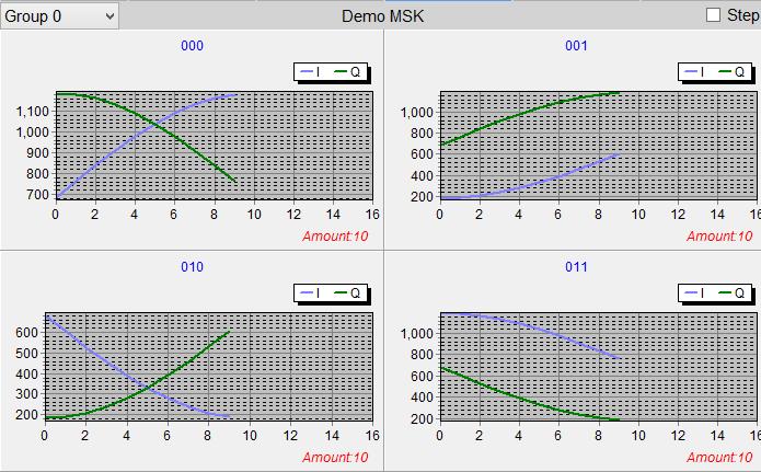
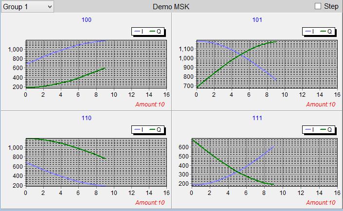
27 PatternI_110,683,605,529,456,390,330,279,238,208,189 PatternQ_110,1183,1177,1159,1129,1088,1037,977,911,838,762 PatternI_111,183,189,207,237,278,329,388,455,527,604 PatternQ_111,684,606,529,457,390,330,279,238,208,189 Page 27 of 27
USB Vector Spectrum Analyzer Operating Manual
 Triarchy VSA6G2A/B USB Vector Spectrum Analyzer Operating Manual CW Signal Spectrum Narrow band FM signal Wide Band FM signal QPSK signal density Cell phone signal at air MSK eye Diagram Waterfall display
TRANSCOM Manufacturing & Education
 www.transcomwireless.com 1 G6 Vector Signal Generator Overview G6 Vector Signal Generator is a high performance vector signal generator. It can generate arbitrary wave signal, continuous wave signal, common
TRANSCOM Manufacturing & Education. Transcom Instruments. Product Brochure TRANSCOM INSTRUMENTS. Product Brochure.
 TRANSCOM INSTRUMENTS Product Brochure Transcom Instruments Product Brochure www.transcomwireless.com 1 Vector Signal Generator Overview Vector Signal Generator is a high performance vector signal generator.
Keysight Technologies
 Keysight Technologies Generating Signals Basic CW signal Block diagram Applications Analog Modulation Types of analog modulation Block diagram Applications Digital Modulation Overview of IQ modulation
Signal Generators for Anritsu RF and Microwave Handheld Instruments
 Measurement Guide Signal Generators for Anritsu RF and Microwave Handheld Instruments BTS Master Spectrum Master Tracking Generator Option 20 Vector signal Generator Option 23 Anritsu Company 490 Jarvis
Transcom Instruments. Product Brochure TRANSCOM INSTRUMENTS. Product Brochure
 TRANSCOM INSTRUMENTS Product Brochure Transcom Instruments Product Brochure Micro-Tx Vector Signal Generator Module Overview Micro-Tx vector signal generator module is a high performance vector signal
G6M VSG Module and A6M VSA Module
 Models ready for System Integration G6M VSG Module and A6M VSA Module Transcom Instruments Overview of G6M G6M vector signal generator module is a high performance vector signal generator. It supports
Mobile Communication An overview Lesson 03 Introduction to Modulation Methods
 Mobile Communication An overview Lesson 03 Introduction to Modulation Methods Oxford University Press 2007. All rights reserved. 1 Modulation The process of varying one signal, called carrier, according
Vector Signal Generator Module. Transcom Instruments.
 Vector Signal Generator Module G6 Transcom Instruments Overview of G6 G6 vector signal generator module is a high performance vector signal generator. It supports arbitrary wave signal, continuous wave
Transcom Instruments. Product Brochure TRANSCOM INSTRUMENTS. Product Brochure
 TRANSCOM INSTRUMENTS Product Brochure Transcom Instruments Product Brochure Vector Signal Generator Overview Vector Signal Generator is a high performance vector signal generator. It can generate arbitrary
SAV102 NB-IoT Modular Signal Generator Datasheet
 SAV102 NB-IoT Modular Signal Generator Datasheet Saluki Technology Inc. The document applies to following models: SAV102 NB-IoT Modular Signal Generator Standard Accessories Main Machine Power adapter
DG5000 series Waveform Generators
 DG5000 series Waveform Generators DG5000 is a multifunctional generator that combines many functions in one, including Function Generator, Arbitrary Waveform Generator, IQ Baseband /IQ IF, Frequency Hopping
PGT313 Digital Communication Technology. Lab 3. Quadrature Phase Shift Keying (QPSK) and 8-Phase Shift Keying (8-PSK)
 and 8-Phase Shift Keying (8-PSK)") PGT313 Digital Communication Technology Lab 3 Quadrature Phase Shift Keying (QPSK) and 8-Phase Shift Keying (8-PSK) Objectives i) To study the digitally modulated quadrature phase shift keying (QPSK) and
PGT313 Digital Communication Technology Lab 3 Quadrature Phase Shift Keying (QPSK) and 8-Phase Shift Keying (8-PSK) Objectives i) To study the digitally modulated quadrature phase shift keying (QPSK) and
PN9000 PULSED CARRIER MEASUREMENTS
 The specialist of Phase noise Measurements PN9000 PULSED CARRIER MEASUREMENTS Carrier frequency: 2.7 GHz - PRF: 5 khz Duty cycle: 1% Page 1 / 12 Introduction When measuring a pulse modulated signal the
Digital Wireless Measurement Solution
 Product Introduction Digital Wireless Measurement Solution Signal Analyzer MS2690A/MS2691A/MS2692A/MS2840A/MS2830A Vector Modulation Analysis Software MX269017A Vector Signal Generator MS269xA-020, MS2840A-020/021,
IQgig-RF TM Model B Technical Specifications
 TECHNICAL SPECIFICATIONS IQgig-RF TM Model B Technical Specifications 2018 LitePoint, A Teradyne Company. All rights reserved. Port Descriptions IQgig-RF Test Controller Front Panel I/O Function Type Power
TSEK02: Radio Electronics Lecture 3: Modulation (II) Ted Johansson, EKS, ISY
 Ted Johansson, EKS, ISY") TSEK02: Radio Electronics Lecture 3: Modulation (II) Ted Johansson, EKS, ISY An Overview of Modulation Techniques chapter 3.3.2 3.3.6 2 Constellation Diagram (3.3.2) Quadrature Modulation Higher Order
TSEK02: Radio Electronics Lecture 3: Modulation (II) Ted Johansson, EKS, ISY An Overview of Modulation Techniques chapter 3.3.2 3.3.6 2 Constellation Diagram (3.3.2) Quadrature Modulation Higher Order
Wireless Communication Systems Laboratory #2. Understanding test equipments. The students will be familiar with the following items:
 Wireless Communication Systems Laboratory #2 Understanding test equipments Objective The students will be familiar with the following items: Signal generation and analysis tools Description of the laboratory
Model 855 RF / Microwave Signal Generator
 Features Very low phase noise Fast switching Phase coherent switching option 2 to 8 phase coherent outputs USB, LAN, GPIB interfaces Applications Radar simulation Quantum computing High volume automated
Signal Forge 1800M Frequency Expansion Module. 1.0 GHz to 1.8 GHz. User Manual
 TM TM Signal Forge 1800M Frequency Expansion Module 1.0 GHz to 1.8 GHz User Manual Technical Support Email: Support@signalforge.com Phone: 512.275.3733 x2 Contact Information Web: www.signalforge.com
DMR Application Note Testing MOTOTRBO Radios On the R8000 Communications System Analyzer
 DMR Application Note Testing MOTOTRBO Radios On the R8000 Communications System Analyzer April 2 nd, 2015 MOTOTRBO Professional Digital Two-Way Radio System Motorola and MOTOTRBO is registered in the U.S.
Signal Forge 2500M Frequency Expansion Module. 1.5 GHz to 2.6 GHz. User Manual
 TM TM Signal Forge 2500M Frequency Expansion Module 1.5 GHz to 2.6 GHz User Manual Technical Support Email: Support@signalforge.com Phone: 512.275.3733 x2 Contact Information Web: www.signalforge.com Sales
DG5000 Series Specifications
 DG5000 Series Specifications All the specifications can be guaranteed if the following two conditions are met unless where noted. The generator is within the calibration period and has performed self-calibration.
LB480A Pulse Profiling USB PowerSensor+ Data Sheet
 Key PowerSensor+ Specifications 100 MHz to 8 GHz (functional to 10 GHz) -60 dbm to +20 dbm 1.95% Total Error* 1.09:1 VSWR (-27 db Return Loss) * Measuring a well matched DUT (-20 dbm @ 1 GHz) Measurement
Application Note: DMR Application Note Testing MOTOTRBO Radios On the Freedom Communications System Analyzer
 : DMR Application Note Testing MOTOTRBO Radios On the Freedom Communications System Analyzer MOTOTRBO Professional Digital Two-Way Radio System Motorola and MOTOTRBO is registered in the U.S. Patent and
IQgig-IF TM Technical Specifications
 TECHNICAL SPECIFICATIONS IQgig-IF TM Technical Specifications 2018 LitePoint, A Teradyne Company. All rights reserved. Port Descriptions IQgig-IF Front Panel I/O Function Type Power Switch Power On/Off
Key Reference. Agilent Technologies E8257D/67D PSG Signal Generators. Manufacturing Part Number: E Printed in USA July 2007
 Agilent Technologies E8257D/67D PSG Signal Generators This guide applies to the following signal generator models: E8267D PSG Vector Signal Generator E8257D PSG Analog Signal Generator Due to our continuing
SynthNV - Signal Generator / Power Detector Combo
 SynthNV - Signal Generator / Power Detector Combo The Windfreak SynthNV is a 34.4MHz to 4.4GHz software tunable RF signal generator controlled and powered by a PC running Windows XP, Windows 7, or Android
Publication Number ATFxxB Series DDS FUNCTION WAVEFORM GENERATOR. User s Guide
 Publication Number 101201 ATFxxB Series DDS FUNCTION WAVEFORM GENERATOR User s Guide Introduction This user's guide is used for all models of ATFxxB series of DDS function generator. xx in the model number
Basic Transceiver tests with the 8800S
 The most important thing we build is trust ADVANCED ELECTRONIC SOLUTIONS AVIATION SERVICES COMMUNICATIONS AND CONNECTIVITY MISSION SYSTEMS Basic Transceiver tests with the 8800S Basic Interconnects Interconnect
Vector Signal Generators
 Vector Signal Generators SG390 Series DC to 2 GHz, 4 GHz and 6 GHz vector signal generators SG390 Series Vector Signal Generators DC to 2 GHz, 4 GHz or 6 GHz Dual baseband arb generators Vector and analog
Vector Signal Generators
 Vector Signal Generators SG390 Series DC to 2 GHz, 4 GHz and 6 GHz vector signal generators SG390 Series Vector Signal Generators DC to 2 GHz, 4 GHz or 6 GHz Dual baseband arb generators Vector and analog
3/26/18. Lecture 3 EITN STRUCTURE OF A WIRELESS COMMUNICATION LINK
 Lecture 3 EITN75 208 STRUCTURE OF A WIRELESS COMMUNICATION LINK 2 A simple structure Speech Data A/D Speech encoder Encrypt. Chann. encoding Modulation Key Speech D/A Speech decoder Decrypt. Chann. decoding
The Icom IC Adam Farson VA7OJ. A New Top-class HF/6m Transceiver. IC-7700 Information & Links
 The Icom IC-7700 A New Top-class HF/6m Transceiver Adam Farson VA7OJ IC-7700 Information & Links Copyright 2008 North Shore Amateur Radio Club NSARC HF Operators IC-7700 1 IC-7700 front panel This is a
Mobile & Wireless Networking. Lecture 2: Wireless Transmission (2/2)
") 192620010 Mobile & Wireless Networking Lecture 2: Wireless Transmission (2/2) [Schiller, Section 2.6 & 2.7] [Reader Part 1: OFDM: An architecture for the fourth generation] Geert Heijenk Outline of Lecture
192620010 Mobile & Wireless Networking Lecture 2: Wireless Transmission (2/2) [Schiller, Section 2.6 & 2.7] [Reader Part 1: OFDM: An architecture for the fourth generation] Geert Heijenk Outline of Lecture
Digital Modulation Lecture 01. Review of Analogue Modulation Introduction to Digital Modulation Techniques Richard Harris
 Digital Modulation Lecture 01 Review of Analogue Modulation Introduction to Digital Modulation Techniques Richard Harris Objectives You will be able to: Classify the various approaches to Analogue Modulation
Objectives. Presentation Outline. Digital Modulation Lecture 01
 Digital Modulation Lecture 01 Review of Analogue Modulation Introduction to Digital Modulation Techniques Richard Harris Objectives You will be able to: Classify the various approaches to Analogue Modulation
AirScope Spectrum Analyzer User s Manual
 AirScope Spectrum Analyzer Manual Revision 1.0 October 2017 ESTeem Industrial Wireless Solutions Author: Date: Name: Eric P. Marske Title: Product Manager Approved by: Date: Name: Michael Eller Title:
LB679A CW and Pulse (Modulation) USB PowerSensor+ Data Sheet
 USB PowerSensor+ Data Sheet") Key PowerSensor+ Specifications 50 MHz to 20 GHz - 40 dbm to +20 dbm 2.8% Total Error* 1.20:1 VSWR (-21 db Return Loss) * Measuring a well matched DUT (-20 dbm @ 2 GHz) Key PowerSensor+ Capability Test
Key PowerSensor+ Specifications 50 MHz to 20 GHz - 40 dbm to +20 dbm 2.8% Total Error* 1.20:1 VSWR (-21 db Return Loss) * Measuring a well matched DUT (-20 dbm @ 2 GHz) Key PowerSensor+ Capability Test
AV4051A/B/C/D/E/F/G/H Signal/Spectrum Analyzer
 AV4051A/B/C/D/E/F/G/H Signal/Spectrum Analyzer 3Hz~4GHz/9GHz/13.2GHz/18GHz/26.5GHz/40GHz/45GHz/50GHz Product Overview: AV4051 series signal/spectrum analyzer has excellent performance in test dynamic range,
Agilent PN 8780A-1 Introductory Operating Guide to the Agilent 8780A Vector Signal Generator. Product Note
 Agilent PN 8780A-1 Introductory Operating Guide to the Agilent 8780A Vector Signal Generator Product Note Table of Contents 3 4 5 5 6 6 8 9 10 10 10 11 12 12 13 14 14 14 14 14 15 15 15 19 19 20 20 21 22
VIAVI Signal Workshop
 Data Sheet VIAVI Signal Workshop Configurable Modular Platform Introduction/Overview Signal Workshop is a fully integrated waveform creation, generation, signal capture, and post-capture analysis software
ME1000 RF Circuit Design. Lab 1. Calibration with Spectrum Analyzer
 ME1000 RF Circuit Design Lab 1 Calibration with Spectrum Analyzer This courseware product contains scholarly and technical information and is protected by copyright laws and international treaties. No
Advanced RF Measurements You Didn t Know Your Oscilloscope Could Make. Brad Frieden Philip Gresock
 Advanced RF Measurements You Didn t Know Your Oscilloscope Could Make Brad Frieden Philip Gresock Agenda RF measurement challenges Oscilloscope platform overview Typical RF characteristics Bandwidth vs.
DSA-815 Demo Guide. Solution: The DSA 800 series of spectrum analyzers are packed with features.
 FAQ Instrument Solution FAQ Solution Title DSA-815 Demo Guide Date:08.29.2012 Solution: The DSA 800 series of spectrum analyzers are packed with features. Spectrum analyzers are similar to oscilloscopes..
Xeta4. Occupied Bandwidth. Measurements
 Xeta4 Occupied Bandwidth Measurements 10/7/2013 Witnessed by Test conducted by Date 10/8/2013 Date 10/8/2013 Page 1 of 39 Introduction... 4 Scope... 4 Equipment Under Test (EUT)... 4 Power Input... 4 Peripheral
Dual Channel Function/Arbitrary Waveform Generators 4050B Series
 Data Sheet Dual Channel Function/Arbitrary Waveform Generators The Dual Channel Function/ Arbitrary Waveform Generators are capable of generating stable and precise sine, square, triangle, pulse, and arbitrary
Rigol DG1022A Function / Arbitrary Waveform Generator
 Rigol DG1022A Function / Arbitrary Waveform Generator The Rigol DG1000 series Dual-Channel Function/Arbitrary Waveform Generator adopts DDS (Direct Digital Synthesis) technology to provide stable, high-precision,
Sigfox RF & Protocol Test Plan for RC1-UDL-ENC-MONARCH
 Version 3.8.0 September 14, 2018 Sigfox RF & Protocol Test Plan for RC1-UDL-ENC-MONARCH Public Use Note: Only the last version of this document available on the Sigfox web sites is official and applicable.
DFS (Dynamic Frequency Selection) Introduction and Test Solution
 Introduction and Test Solution") DFS (Dynamic Frequency Selection) Introduction Sept. 2015 Present by Brian Chi Brian-tn_chi@keysight.com Keysight Technologies Agenda Introduction to DFS DFS Radar Profiles Definition DFS test procedure
DFS (Dynamic Frequency Selection) Introduction Sept. 2015 Present by Brian Chi Brian-tn_chi@keysight.com Keysight Technologies Agenda Introduction to DFS DFS Radar Profiles Definition DFS test procedure
Sigfox RF & Protocol Test Plan for RC2-UDL-ENC
 Version 380 September 14, 2018 Sigfox RF & Protocol Test Plan for RC2-UDL-ENC Public Use Note: Only the last version of this document available on the Sigfox web sites is official and applicable This document
TSEK02: Radio Electronics Lecture 2: Modulation (I) Ted Johansson, EKS, ISY
 Ted Johansson, EKS, ISY") TSEK02: Radio Electronics Lecture 2: Modulation (I) Ted Johansson, EKS, ISY 2 Basic Definitions Time and Frequency db conversion Power and dbm Filter Basics 3 Filter Filter is a component with frequency
TSEK02: Radio Electronics Lecture 2: Modulation (I) Ted Johansson, EKS, ISY 2 Basic Definitions Time and Frequency db conversion Power and dbm Filter Basics 3 Filter Filter is a component with frequency
Agilent N7509A Waveform Generation Toolbox Application Program
 Agilent N7509A Waveform Generation Toolbox Application Program User s Guide Second edition, April 2005 Agilent Technologies Notices Agilent Technologies, Inc. 2005 No part of this manual may be reproduced
Sigfox RF & Protocol Test Plan for RC3c-UDL-ENC
 Version 3.8.0 September 14, 2018 Sigfox RF & Protocol Test Plan for RC3c-UDL-ENC Public Use Note: Only the last version of this document available on the Sigfox web sites is official and applicable. This
Spectral Monitoring/ SigInt
 RF Test & Measurement Spectral Monitoring/ SigInt Radio Prototyping Horizontal Technologies LabVIEW RIO for RF (FPGA-based processing) PXI Platform (Chassis, controllers, baseband modules) RF hardware
PGT313 Digital Communication Technology. Lab 6. Spectrum Analysis of CDMA Signal
 PGT313 Digital Communication Technology Lab 6 Spectrum Analysis of CDMA Signal Objectives i) To measure the channel power of a CDMA modulated RF signal using an oscilloscope and the VSA software ii) To
Spectrum Analyzing & Interference Locating
 Spectrum Analyzing & Interference Locating SpecMini Handheld Spectrum Analyzer Frequency Range: 9kHz to 6.0GHz DANL: -168dBm@1GHz Android Operating System: touch screen operation, multitouch, easy-to-use
8853Q Spectrum Analyzer
 Increases Productivity by Providing a Complete Set of Spectrum Analysis Tests in One Instrument Intuitive User Interface Shortens Learning Curve Full-Featured, High-Performance, Remote Operation Automated
GET10B Radar Measurement Basics- Spectrum Analysis of Pulsed Signals. Copyright 2001 Agilent Technologies, Inc.
 GET10B Radar Measurement Basics- Spectrum Analysis of Pulsed Signals Copyright 2001 Agilent Technologies, Inc. Agenda: Power Measurements Module #1: Introduction Module #2: Power Measurements Module #3:
Ascent Ground and Satellite Demonstration
 Ascent Ground and Satellite Demonstration By Ray Roberge, WA1CYB & Howie DeFelice, AB2S WA1CYB s1 Big Picture Goals Place more capable satellites into higher orbits Utilize software defined radios A programmable
Vector Signal Analyzer FSE-B7 for Spectrum Analyzers FSE
 Vector Signal Analyzer FSE-B7 for Spectrum Analyzers FSE Universal demodulation, analysis and documentation of digital and analog mobile radio signals For all major mobile radio communication standards:
MG3740A Analog Signal Generator. 100 khz to 2.7 GHz 100 khz to 4.0 GHz 100 khz to 6.0 GHz
 Data Sheet MG3740A Analog Signal Generator 100 khz to 2.7 GHz 100 khz to 4.0 GHz 100 khz to 6.0 GHz Contents Definitions, Conditions of Specifications... 3 Frequency... 4 Output Level... 5 ATT Hold...
LB680A Pulse Profiling USB PowerSensor+ Data Sheet
 Key PowerSensor+ Specifications 50 MHz to 20 GHz - 40 dbm to +20 dbm 2.8% Total Error* 1.20:1 VSWR (-21 db Return Loss) * Measuring a well matched DUT (-20 dbm @ 2 GHz) Measurement Capability Time Gated
SIGNAL GENERATORS. MG3633A 10 khz to 2700 MHz SYNTHESIZED SIGNAL GENERATOR GPIB
 SYNTHESIZED SIGNAL GENERATOR MG3633A GPIB For Evaluating of Quasi-Microwaves and Measuring High-Performance Receivers The MG3633A has excellent resolution, switching speed, signal purity, and a high output
MODEL 625A SMARTARB BNC A BEST BUY. Eliminates Phase Jitter
 A BEST BUY The Model 625A SMARTARB was designed to provide more operating modes, more functions and more measurement modes than any other unit in its price class. Further upgrading and additions of these
Model 745 Series. Berkeley Nucleonics Test, Measurement and Nuclear Instrumentation since Model 845-HP Datasheet BNC
 Model 845-HP Datasheet Model 745 Series Portable 20+ GHz Microwave Signal Generator High Power +23dBM Power Output 250 fs Digital Delay Generator BNC Berkeley Nucleonics Test, Measurement and Nuclear Instrumentation
DFS Test Report : IWAVEPORT WLM200NX : 08B005S
 DFS Test Report Product Name : WIRELESS-N NETWORK MINI PCI ADAPTER Model No. : IWAVEPORT WLM200NX Applicant : Compex Systems Pte Ltd Address : 135 Joo Seng Road, #08-01 PM Industrial Building Singapore
Suitable firmware can be found on Anritsu's web site under the instrument library listings.
 General Caution Please use a USB Memory Stick for firmware updates. Suitable firmware can be found on Anritsu's web site under the instrument library listings. If your existing firmware is older than v1.19,
Pulsed S-Parameter Measurements using the ZVA network Analyzer
 Pulsed S-Parameter Measurements using the ZVA network Analyzer 1 Pulse Profile measurements ZVA Advanced Network Analyser 3 Motivation for Pulsed Measurements Typical Applications Avoid destruction of
Wireless Communication Fading Modulation
 EC744 Wireless Communication Fall 2008 Mohamed Essam Khedr Department of Electronics and Communications Wireless Communication Fading Modulation Syllabus Tentatively Week 1 Week 2 Week 3 Week 4 Week 5
CLOUDSDR RFSPACE #CONNECTED SOFTWARE DEFINED RADIO. final design might vary without notice
 CLOUDSDR #CONNECTED SOFTWARE DEFINED RADIO final design might vary without notice 1 - PRELIMINARY SPECIFICATIONS http://www.rfspace.com v0.1 RFSPACE CloudSDR CLOUDSDR INTRODUCTION The RFSPACE CloudSDR
Measurement Guide and Programming Examples
 Measurement Guide and Programming Examples N9073A-1FP W-CDMA Measurement Application N9073A-2FP HSDPA/HSUPA Measurement Application For use with the Agilent N9020A MXA and N9010A EXA Signal Analyzers Manufacturing
Keysight Technologies N9051B Pulse Measurement Software X-Series Signal Analyzers. Technical Overview
 Keysight Technologies N9051B Pulse Measurement Software X-Series Signal Analyzers Technical Overview 02 Keysight N9051B Pulse Measurement Software X-Series Signal Analyzers - Technical Overview Features
NOW WITH UP TO 40 GHz BANDWIDTH
 NOW WITH UP TO 40 GHz BANDWIDTH IQTransmitter Industry Leading High Bandwidth of 40 GHz Full & Emulated Dual-Polarization IQTransmitter Your choice of 40 GHz, 26 GHz or 11 GHz of bandwidth Pattern independent
Signal Forge. Signal Forge 1000 TM Synthesized Signal Generator. Flexible Design Enables Testing of RF and Clock-driven Systems.
 Signal Forge TM Signal Forge 1000 TM Synthesized Signal Generator L 8.5 W 5.4 H 1.5 Flexible Design Enables Testing of RF and Clock-driven Systems The Signal Forge 1000 combines a 1 GHz frequency range
LB480A Pulse Profiling USB PowerSensor+ Data Sheet
 Key PowerSensor+ Specifications 50 MHz to 8 GHz (functional to 10 GHz) - 60 dbm to +20 dbm 1.95% Total Error* 1.09:1 VSWR (-27 db Return Loss) * Measuring a well matched DUT (-20 dbm @ 1 GHz) No Zero No
SETTING UP A WIRELESS LINK USING ME1000 RF TRAINER KIT
 SETTING UP A WIRELESS LINK USING ME1000 RF TRAINER KIT Introduction S Kumar Reddy Naru ME Signal Processing S. R. No - 05812 The aim of the project was to try and set up a point to point wireless link.
Analog Arts SF900 SF650 SF610 Product Specifications
 www.analogarts.com Analog Arts SF900 SF650 SF610 Product Specifications Analog Arts reserves the right to change, modify, add or delete portions of any one of its specifications at any time, without prior
Application Note: Testing P25 Conventional Radios Using the Freedom Communications System Analyzers
 : Testing P25 Conventional Radios Using the Freedom Communications System Analyzers FCT-1007A Motorola CPS and Tuner Software Motorola provides a CD containing software programming facilities for the radio
Agilent. E8267C PSG Vector Signal Generator E8257C PSG Analog Signal Generator E8247C PSG CW Signal Generator
 Agilent E8267C PSG Vector Signal Generator E8257C PSG Analog Signal Generator E8247C PSG CW Signal Generator Aerospace and defense systems Component measurements Satellite communications Broadband microwave
Analog Arts SG985 SG884 SG834 SG814 Product Specifications [1]
![Analog Arts SG985 SG884 SG834 SG814 Product Specifications [1]](/thumbs/94/122371203.jpg "Analog Arts SG985 SG884 SG834 SG814 Product Specifications [1]") www.analogarts.com Analog Arts SG985 SG884 SG834 SG814 Product Specifications [1] 1. These models include: an oscilloscope, a spectrum analyzer, a data recorder, a frequency & phase meter, and an arbitrary
www.analogarts.com Analog Arts SG985 SG884 SG834 SG814 Product Specifications [1] 1. These models include: an oscilloscope, a spectrum analyzer, a data recorder, a frequency & phase meter, and an arbitrary
TC-3000C Bluetooth Tester
 TC-3000C Bluetooth Tester Product Instructions TC-3000C Bluetooth Tester is able to analyze the data of every packet that is transmitted to the upper application protocol layer using the protocol stack,
Dive deep into interference analysis
 Dive deep into interference analysis Dive deep into interference analysis Contents 1. Introducing Narda Outstanding features 2. Basics IDA 2 3. IDA 2 presentation How IDA 2 is used: 1) Detect 2) Analyze
Testing Motorola P25 Conventional Radios Using the R8000 Communications System Analyzer
 Testing Motorola P25 Conventional Radios Using the R8000 Communications System Analyzer Page 1 of 24 Motorola CPS and Tuner Software Motorola provides a CD containing software programming facilities for
IC-400pro - RADIOAFICION.COM
 PROCEDURES IC-400pro - 5- PREPARATION When you adjust the contents on pages 5-5 and 5-6, SOFT- WARE, the optional CS-400PRO ADJ SOFTWARE (Rev..0 or later), *OPC- JIG CABLE (modified OPC- CLONING CABLE;
Environment Signals Plug-in Application Printable Help Document
 xx ZZZ Environment Signals Plug-in Application Printable Help Document *P077140100* 077-1401-00 ZZZ Environment Signals Plug-in Application Printable Help Document www.tek.com 077-1401-00 Copyright Tektronix.
Sigfox Verified TM. Modem Test Plan for RC5-UDL-ENC. Version August 10, Public Use
 Version 3.7.1 August 10, 2018 Sigfox Verified TM Modem Test Plan for RC5-UDL-ENC Public Use Note: Only the last version of this document available on the Sigfox web sites is official and applicable. This
Chapter 7. Multiple Division Techniques
 Chapter 7 Multiple Division Techniques 1 Outline Frequency Division Multiple Access (FDMA) Division Multiple Access (TDMA) Code Division Multiple Access (CDMA) Comparison of FDMA, TDMA, and CDMA Walsh
Understanding RF and Microwave Analysis Basics
 Understanding RF and Microwave Analysis Basics Kimberly Cassacia Product Line Brand Manager Keysight Technologies Agenda µw Analysis Basics Page 2 RF Signal Analyzer Overview & Basic Settings Overview
R3477. Ideal for mobile communication applications including base stations and handsets, from the development stage to production and installation
 R3477 Signal Analyzers Ideal for mobile communication applications including base stations and handsets, from the development stage to production and installation Frequency range: 9 khz to 13.5 GHz World
GAO-SAU-105 Spectrum Analyzer with Wide Frequency Range
 GAO-SAU-105 Spectrum Analyzer with Wide Frequency Range GAOTek Spectrum Analyzer with Wide Frequency Range has excellent performance to test dynamic range, phase noise, amplitude accuracy and test speed.
Addressing the Challenges of Wideband Radar Signal Generation and Analysis. Marco Vivarelli Digital Sales Specialist
 Addressing the Challenges of Wideband Radar Signal Generation and Analysis Marco Vivarelli Digital Sales Specialist Agenda Challenges of Wideband Signal Generation Challenges of Wideband Signal Analysis
Chapter 6 Specifications
 RIGOL This chapter describes the specifications of RF signal generator. Specifications are valid under the following conditions: the instrument in the calibration cycle is stored at least two hours at
Windfreak Technologies SynthHD v1.4 Preliminary Data Sheet v0.2b
 Windfreak Technologies SynthHD v1.4 Preliminary Data Sheet v0.2b $1299.00US 54 MHz 13.6 GHz Dual Channel RF Signal Generator Features Open source Labveiw GUI software control via USB Run hardware functions
IQgig-RF TM Technical Specifications
 TECHNICAL SPECIFICATIONS IQgig-RF TM Technical Specifications 2017 LitePoint, A Teradyne Company. All rights reserved. IQgig-RF is a scalable physical-layer test solution, tailored for 802.11ad (WiGig)
BER Performance with GNU Radio
 BER Performance with GNU Radio Digital Modulation Digital modulation is the process of translating a digital bit stream to analog waveforms that can be sent over a frequency band In digital modulation,
Signal Forge. Signal Forge 1000 TM Synthesized Signal Generator. Digital and RF Tester with 1 GHz Range. Key Features
 Signal Forge TM Signal Forge 1000 TM Synthesized Signal Generator L 8.5 W 5.4 H 1.5 Digital and RF Tester with 1 GHz Range The Signal Forge 1000 combines a 1 GHz frequency range with three dedicated outputs
ICOM IC-R8600 Specifications, Features & Options
 General Frequency coverage IC-R8600 USA: 0.010000 821.999999MHz*, 851.000000 866.999999MHz, 896.000000 3000.000000MHz (*Guaranteed range: 0.100000 821.999999MHz) Antenna connector Frequency stability Mode
Analog Arts SF990 SF880 SF830 Product Specifications
 1 www.analogarts.com Analog Arts SF990 SF880 SF830 Product Specifications Analog Arts reserves the right to change, modify, add or delete portions of any one of its specifications at any time, without
Ideal for high dynamic range measurements from compression to noise floor
 USB/Ethernet Very Wideband Synthesized Signal Generator 5Ω -75 dbm to +14 dbm, 25 khz - 64 MHz The Big Deal Cost effective production test solution Power level resolution of.1 db Frequency resolution under.1