229mm. 186mm. 212mm. 113mm. 255mm. 81mm. 216mm. 33.2mm. Specifications
|
|
|
- Josephine Dickerson
- 5 years ago
- Views:
Transcription
1 80 Size FPV Racer Fully Assembled: No building or firmware loading necessary! On-Screen Display (OSD): Program or set up your Vengeance on-the-fly, no computer needed. In-Flight-Adjustable Single-Axis Camera Gimbal, Selfleveling during flight. Vibration Dampened Second-Camera Mount. Robust, Pure Carbon-Fiber Frame with Carbon Exoskeleton Reinforcements. Stress-Flex Designed to Withstand Impacts, Mass centralized for high-rate turning. Black-Anodized, High-Strength CNC Aluminum Boom Mounts. Tough, Translucent Polymer Landing Legs with Built-in Directional Red-Green LED. 8 Forward-Tilt Motor Mounts for Aerodynamic Efficiency and Top Speed Performance. Four 04, 300Kv High-Output Brushless Motors. Custom Compact BL-Heli 0A Motor Controllers (ESC). Visual LED Flight Mode Indicator. Easy to confirm your flight mode. Pre-loaded with Three Flight Modes: Normal, Altitude Hold, or Acro Mode. NAZE Spec 3 Bit Flight Controller 7DOF (with BMP sensor). Altitude Hold via Integrated Barometric Pressure Sensor (BMP). 3S and 4S Battery Compatible. Hyperion G6 HV LiPo Suggested. 5.8GHz Auto-Scan 40CH Video Transmitter (VTX) w/ Race Band VTX selectable for either 5mw/00mw output. Tuned 5.8GHz CloverLeaf Skew-Planar Antenna. Plug-n-Play Ready for Optional GPS modules. Built-in Low-voltage Audible Alarm. Compatible with Single Wire* or Traditional Receivers (*S-Bus, Horizon Spektrum Satellite, or Hyperion Compatible receivers). Box includes Carry Handle and Foam Racer Cradle + Parts Holder, for service as field case. One Set 6x4 CC/CCW Propellers Included.
2
3 9mm 86mm m m 80 mm 3mm 55mm 6mm Specifications 8mm 33.mm Length 6mm Channels 6 8ch Motors Hyperion kVㄈ Width 55mm Camera 600tvl /3" CMOS Camera ESC BL Heli 0A Diagonal Base 80mm VTX 5.8Ghz mW selectable w/ 40Ch's Propellers 6040 CW & CCW Weight 435g w/o battery Battery 3~4S Compatible Controller Naze3 w/ OSD & Altitude Sensor


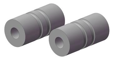

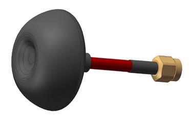

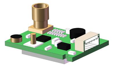


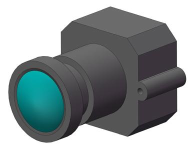

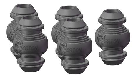

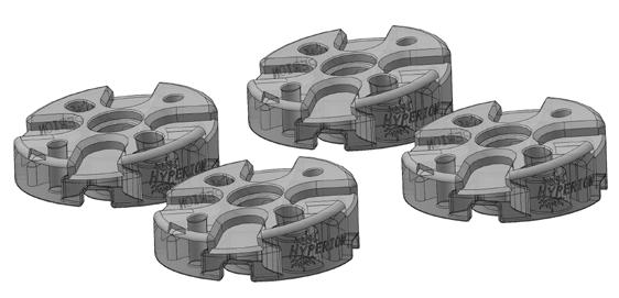

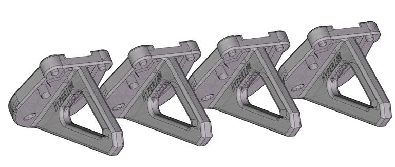

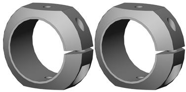


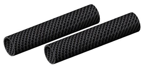

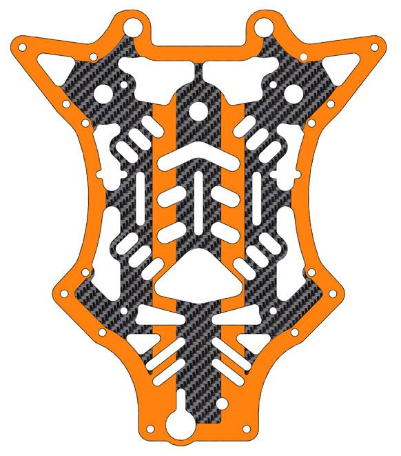


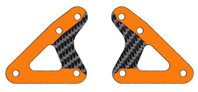

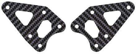

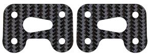

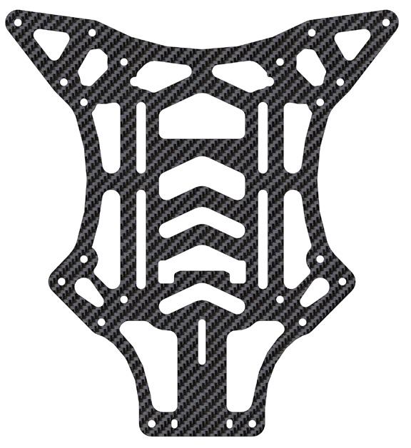

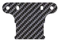

4 Lower Front Reinforcement Plates Main Carbon Fibre Frame Lower Main Carbon Fibre Frame Main Frame Mounting Clamps 4 Left / Right Reinforcement Plate Motor Mounting Clamps 4 Front Arm Reinforcement Clamps Camera Mounting Plate Lower Rear Reinforcement Plates VTX Mounting Plate Vengeance Carbon Fiber Frame Kit Rear Frame Standoff Rear Frame Standoff 9mm 0mm 6x4 CW + CCW Prop Set (Black) Hyperion Silicon Dampeners Soft 5 Front Arm Tubes 5 73mm Rear Arms Tubes 5 83mm 6x4 CW + CCW Prop Set (Orange) Hyperion kv Brushless Motor CW Hyperion kv Brushless Motor CCW BL Heli 0A S~4S ESC 4 Eight Degree Forward Tilt Motor Mounts 4 5.8GHz Cloverleaf RHCP 5. 8 G H z S e l e c t a b l Flight Controller with OSD, and Altitude Antenna (RP-SMA) e 5mW / 00mW Video Sensor Transmitter /3" 600tvl CMOS Camera Mount V e n g e a n c e Gimbal Mount Camera Bracket Gimbal Motor Bracket with Sensor (axis Pitch) Vengeance Translucent Landing Gear 4 LED Landing Gear LED Landing Gear PCB (Red) PCB (Green)


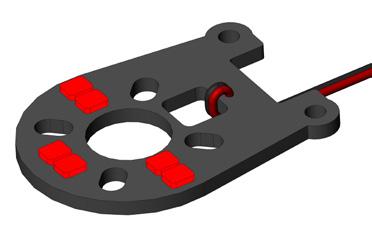
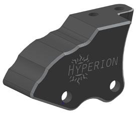
5 .Motor & Arm The Vengeance's unique motor mount design allows for superb forward flight and cornering performance. Please note that during installation that you install each arm in the proper location and the angle of motors and motor rotation corresponds to the picture enclosed. 9 6 m m m m Motor mount arrows Clockwise Rotation indicated forward position <<<< Motor Rotation Indicators. 9 m m of the motor. Hyperion kv Counterclockwise Rotation >>>> Motor Rotation Indicators. Eight Degree Forward Tilt Motor Mounts M3 6mm Motor Rotation Chart. Motor Mount Assembly Direction Chart. LED Landing Gear Assembly Chart 3


6 BL Heli 0Amp ESC ~4S LED Landing Gear PCB Translucent Landing Gear M3 x 0mm Self-tapping Screw Motor Mount Arm Clamps M.5 0mm Hex Screw 5mm Arm Tubes Arm & 3 use 5 73mm Arm & 4 use 5 83mm M.5 6mm Hex Screw.VTX Assembly Double Side Adhesive Tape 5.8GHz Selectable 5mW / 00mW Video Transmitter Heat shrink tube VTX Mounting Plate 4


7 3.Main Frame Assembly Frame Mount Clamps M.5 Self Locking Nut Frame Mount Clamps Flight Controller Front Arm Reinforcement Clamps M.5 Self Locking Nut Lower Rear Reinforcement Plates Lower Front Reinforcement Plates Lower Main Carbon Fibre Frame M.5 4mm M.5 8mm M.5 8mm M.5 4mm M.5 8mm M.5 4mm M.5 4mm M.5 0mm M.5 4mm M.5 0mm M.5 8mm M.5 0mm M.5 0mm M.5 4mm Rear Frame Standoff 0mm Rear Frame Standoff 9mm NOTE: use the "Video Out" plug to connect to your VTX. "Video IN" plug is used to connect to the Camera. M.5 6mm 5


8 4. Main Arm Assembly M M4 M M3 90 to Main Frame Plate Make sure that the landing gear plate is 90 to the main frame plate. Once you have confirmed the landing gear plate is 90 to the main frame plate you can then fasten the clamp screw. Positive ESC Power Supply Negative ESC Power Supply PWM Throttle Signal Wire Before Flying make sure your wires are correctly plugged into the proper color receptacle. Insert the LED Landing Gear Light Indicator in the plug. 6


9 5. Camera Mounting Assembly M.5 4mm Camera Mounting Plate Gimbal Mount Bracket Vengeance Silicone Dampeners (Soft) 5 M.5 4mm /3" 600tvl CMOS Camera Vengeance Gimbal Motor with Sensor (-axis Pitch) M.5 6mm Left Reinforcement Plate Right Reinforcement Plate Main Carbon Fibre Frame M.5 Self Locking Nut M.5 4mm M.5 6mm M.5 6mm M.5 6mm M.5 6mm M.5 4mm 7


10 6. Frame Final Assembly # Nut rotation # Nut rotation 5.8GHz Cloverleaf RHCP Antenna (RP-SMA) #4 Nut rotation # Propeller rotation # Propeller rotation #4 Propeller rotation #3 Nut rotation #3 Propeller rotation 4 3 NOTE: Do not power on the the VTX without installing the antenna first. Failure to do so may harm the VTX and cause it to fail. M.5 8mm M-M4Motor Rotation and Arm Placement Chart. Complete!! 8

 S.")

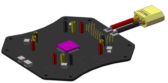
11 INSTRUCTION 7. Vengeance Flight Controller Details Video IN and Gimbal Control Plug Video OUT Plug Auxiliary Video IN Solder Points V LED 5V LED #4 Arm ESC Bullet Connectors Auxiliary Video OUT Solder Points LED Landing Gear Light Plug LED Landing Gear Light Plug Spektrum Compatible Satellite Receiver Input Futaba S.BUS Compatible # Arm ESC Bullet Connectors USB function switch 8MB Flash Memory Flight Mode Status Indicator ON Micro USB Plug Satellite Receiver Input OSD (On-ScreenDisplay Module) S.BUS ON/OFF Switch LED Landing Gear Light Plug 3456 SCL RUCTION SDA 3.3V GND TX Function Switch ON BMP Sensor 3456 INSTRUCTION #3 Arm ESC Bullet Connectors Flight contorl SettingU S B&F l i gupgrade ht Controller OSD Buzzer Setting & Upgrade LED Landing Gear Light Plug # Arm ESC Bullet Connectors ON LED Rear Lights LED Rear Lights 3456 Normal Flight FrSky GND RxD Receiver Imput RX GND ADC IN GPIO GFIO /FT XT-60 Power Connector. 3~4S Compatible HvLi/LiPo USB function switch Receiver Connection GND 5V This is the PWM Input Flight contorl Channel Chart. Plug Setting &Receiver Upgrade 3456 servo each corresponding ON lead into the correct3channel OSD 4 After the correct polarity. Setting &with Upgrade been wire installation has ON made please make sure to check in CleanFlight6Software Normal that your "Channel Map" Flight is consistent with your7brand of 3456 Transmitter. DO NOT ARM Vengeance with propellers on 8 ON GND DC5V + Controller Function Roll (AIL) USB Flight ON 34 ON for the first time without checking! Receiver Connection GND 5V GND DC5V + Roll (AIL) Pitch (ELE) Throttle(THR) Yaw (RUD) AUX(Fly mode) AUX(Camera Gimbal) AUX3 AUX4 function switch Switch Pitch (ELE) Flight Controller Throttle(THR) Flight contorl Programming & Yaw (RUD) Setting & Upgrade Upgrade AUX(Fly mode) 5AUX(Camera 6 Gimbal) AUX3 AUX4 OSD Programming & 3456 ON 3456 OSD Upgrade Setting & Upgrade Flight Mode (must be selected Normal Flightfor flight) Receiver Connection 9


12 8.SetUp CleanFlight. Download Google Chrome Browser, go to Chrome Application Webstore and download "CleanFlight" and install it. If it is your first-time installation of Cleanflight you must click "Here" to download and install "CP0X Drivers" After properly connecting the Vengeance via the Micro USB plug to CleanFlight Software the program should resemble your quadcopters position. Here is the Main Menu options page. You may Calibrate and update your flight parameters and other settings. You can also update and backup your flight controller settings. By default select UART for standard PWM input Receivers. When using Spektrum or other PPM input receivers you must select UART Serial RX and turn ON DO NOTE! You must "Save and Reboot" to save changes onto your flight controller. 0

13 By default the Vengeance comes loaded with all preset options. The Default parameters are to be used with standard PWM input receivers. If you would like to use a PWM or S.BUS style receiver you must configure these settings yourself. Receiver Mode: If you are using a Satellite Receiver or PPM input you may select the type of Receiver here. For example: Spektrum PPM or Futaba S.BUS. By default the Vengeance is setup to use standard PWM signal. The user must use a 6Ch Transmitter to utilize the Vengeances standard functions ( 5Ch. Flight Mode Selection, 6Ch. Gimbal Control) "Serial Receiver Provider" option allows you to select the type of PPM (single-line) input Receiver you are using. If you edit the Receiver Input type please make sure DO NOT ARM motors until you have verified that your "Channel MAP" corresponds to your Transmitter. Failure to do so can lead to possible bodily damage. DO NOTE! You must "Save and Reboot" to save changes onto your flight controller.

14 The "Receiver" directory of CleanFlight helps to show you your Channel Map and the position of your Transmitters controls with respect to the Flight Controller. Under the "Channel Map" option please choose if you are using Futaba / Hitec or JR / Spektrum / Graupner. DO NOTE! You must "Save and Reboot" to save changes onto your flight controller. Channel Map Default Futaba Hitec JR Spektrum Graupner Roll Roll Throttle Pitch Pitch Roll 3 Throttle Throttle Pitch 4 Yaw Yaw Yaw 5 Aux Aux Aux 6 Aux Aux Aux 7 Aux3 Aux3 Aux3 8 Aux4 Aux4 Aux4 Radio Channel Revers Pitch Throttle Throttle Pitch Futaba Hitec JR Spektrum Graupner Roll Reverse Throttle Normal Pitch Normal Roll Reverse 3 Throttle Reverse Pitch Normal 4 Yaw Normal Yaw Reverse 5 Aux Aux 6 Aux Aux 7 Aux3 Aux3 8 Aux4 Aux4 Yaw MODE The colored indication bars in CleanFlight represent your real time channel PWM signal. Make sure to turn your Transmitter ON so you may check your trim and to Roll Yaw MODE make sure your channels moves in the correct direction. Left Pitch UP (Stick Low) Left Low Flight Mode Change Gimbal DOWN It is important to note that when you move your Transmitter sticks that your Transmitters Travel Adjustment (ATV) must move to less than 00 and more than 900. If your Transmitters Travel Adjustment is not properly setup than your Vengeance will not ARM. To ARM your Vengeance move your YAW/RUDDER stick to the Bottom and RIGHT position for - seconds. DO NOT ARM Vengeance with propellers on for the first time! Right Roll Pitch Down (Stick Hight) Right High Flight Mode Change Gimbal UP Radio End Point / ATV Setting Futaba Hitec JR Spektrum Graupner Roll 0/0% Throttle 0/0% Pitch 0/0% Roll 0/0% 3 Throttle 0/0% Pitch 0/0% 4 Yaw 0/0% Yaw 0/0% 5 Aux 0/0% Aux 0/0% 6 Aux 0/0% Aux 0/0% 7 Aux3 0/0% Aux3 0/0% 8 Aux4 0/0% Aux4 0/0%


 is \"Race Mode\". The second mode is \"Self-Level Mode\".")

: While in Race Mode the camera will dampen any oscillations during flight")

15 9. Gimbal Mode and Settings The Vengeance utilizes a brushless gimbal for pitch dampening and view adjustment..when turning ON the Vengeance please keep the Vengeance level and do not move for about 5 seconds. The gimbal sensors must detect the horizontal position..make sure that the Gimbal's wires are not tangled and are able to move freely. Failure to free the Gimbal head from obstructions may lead to the Gimbal motor to fail. Mode Change Button 3.W h e n p o w e r i s plugged in on the Vengeance if the g i m b a l v i b r a t e s a n d o s c i l l a t e s uncontrollable then reset the power and power again. 4.After the gimbal is set and detects horizontal positioning after 5 seconds you may rotate the gimbal with your hand to find your desired camera view angle. 5.Ch.6 on your PWM Receiver can be used to control the Gimbal rotation UP or DOWN. or Gimbal Down How To Change Gimbal Stabilization Modes: There are two types of gimbal stabilization modes. First mode (by default) is "Race Mode". The second mode is "Self-Level Mode". To change between modes quickly press the "Mode Change Button" twice with a small tool. DO NOTE: Mode switching cannot be remembered by the gimbal after unplugging the battery. When you unplug the battery from the Vengeance the gimbal will reset to "Race Mode" by default. Gimbal UP RACE MODE (Default): While in Race Mode the camera will dampen any oscillations during flight while viewing in the Vengeances general preset camera view angle. Oscillations under 0.4seconds will be dampended out. Race Mode is designed to dampen rapid changes in pitch thus stabilizing your view. RACE Mode (Preset) SELF-LEVEL MODE (Secondary): While in Self-Level Mode the gimbal will fully stabilize the camera angle parralel to the ground. This mode is recommended for beginners or people wanting a more stabilized view. SELF-LEVEL Mode (Preset) PPM Receiver and Gimbal Note: While using RACE MODE adjusting the camera angle via PPM is not supported. SELF-LEVEL MODE is not supported via PPM wire. If you wish to have full-access to your camera gimbal you must use a standard PWM receiver. 3
16 PID Tuning Configuration. PID Tuning is used to adjust the flight characteristics. Default PID settings for the Vengeance is set for beginners and intermediate pilots. If you wish to fly faster you may reduce the ROLL and PITCH PID settings both by -0. for reduced sensitivity. If you wish to increase the sensitivity of the Vengeance's ROLL / PITCH/ YAW you may increase the PID settings to no more than 0.8, otherwise it will be difficult to control. DO NOTE! You must "Save and Reboot" to save changes onto your flight controller. The Vengeance includes three preset flight modes. The fight mode switch is used on Ch.5 of your transmitter, a three-position toggle switch is recommended. 0 0: ANGLE: For beginners use. Features automatic level stabilization. *Due to the eight degree forward motor-tilt the Vengeance will naturally try to fly slightly forward while hovering. : ANGLE + BARO: For beginners use. Features automatic level stabilization. Integrated BMP sensor will automatically will try to hold the flight altitude. : Manual: For advance use. Disables automatic level stabilization. Used for rolls and flips. DO NOTE! You must "Save and Reboot" to save changes onto your flight controller.

17 "Adjustments" Configuration Page: Here is where you can set advanced features on the Vengeance via AUX channels on your Transmitter. It is important to understand all the functions that you enable. Check your AUX channel's by looking at the "Channel Map" configuration page. Motor Configuration Page: This page is used to adjust your motor settings if you wish to do so, though the Vengeance becomes already pre-configured. Before testing this feature make sure to remove ALL propellers before trying. Failure to do so may result in bodily harm. How to configure your ESC adjustments: The Vengeance uses four different motors and ESC's. Sometime there might be a inconsistent distrubtion of power among your Vengeance which could lead to poor flight performanc and handling. To reset your ESC and tune them properly please follow the below steps:. Remove ALL propellers before configuration! Failure to do so may lead to bodily harm.. Connect the Flight Controller to CleanFlight without the main flight battery connected Turn the motor "Test Switch On" 3 4. Move the "Master" switch to the maximum level 5. Connect the main flight battery to the Vengeance. Wait five seconds after the ESC makes a gradual rise in noise 6. Move the "Master" switch to the minium level, you will 4 hear a gradual decline in ESC sound. 7. Turn OFF the Master Switch and unplug the flight battery.
 3.")


18 0.How to bind Spektrum satellite receiver?. Go to the "Ports" page. Under the UART page area activate the "Serial RX" tab. (Press Save and Reboot). Go to the "Configuration" page. Select the RX_Serial option and whether you are using Spektrum 04 or 048 compatible receivers. (Press Save and Reboot) 3. Go to the "Receiver" page. Select the Channel Map for JR/ Spektrum/Graupner radios. (Press Save and Reboot) 4. Enter into the command line the following code: "Set spektrum_sat_ = X" "Enter" X Value = Receiver mode 3 = DSM 04bit / ms 5 = DSM 048bit / ms 7 = DSMX 04bit / ms 9 = DSMX 048bit / ms 5. Insert "Save" and press Enter. A Message pop-up will appear "Save & Rebooting." 6. Unplug the USB, then immediately reconnect USB. 7. The satellite receiver LED will start to flash. 8. Hold the Bind switch on your transmitter and turn ON. 9. The Satellite receiver LED will dim and then reappear. You are now binded. 6


19 . Configuring your VTX. The Vengeance utilizes a 5.8GHz Selectable 5mW / 50mW Video Transmitter with 40Ch's with Raceband. Changing Channels and Bands: Push button for more than Seconds: Change Band. Push button for less than Second: Change Frequency Channel. The Vengeance's VTX utilizes a 5mW and 50mW selectable VTX. In most European and Western Countries 5mW is the maximum Rf output for 5.8Ghz. Please check with your law and regulations to make sure that you confirm with the law. Adjusting the Rf power output for increased range. You may cut the "RF limit wire" so that you may transmit at 00mW power. If you wish to later transmit at 5mW you may solder the "RF limit wire" again. Change RF Output? Hyperion FXT 5.BGHz 40 Channel AV Transmitter Modulate Video Format Characteristics Wideband FM Modulate NTSC / PAL Value Min. Typ. Max. Units Output Impedance Ohm Output Power FX795T-L/ 5mW 3 4 dbm FX795T-/00mW 3 4 dbm 3 Frequency Range Mhz 4 Operating Voltage V 5 Supply current FX795T-L/ 5mW ma FX795T-/00mW ma 6 Output Voltage(VOUT) VOUT=5V V 7 Operating Temperature Video Band Width Mhz 9 Audio Carrier Frequency Mhz 0 Video Input Level Vp-p Video Input Impedance Ohm Audio Input Level Vp-p 3 Audio Input Impedance 0K Ohm 4 Weight Gram(s) 5 Antenna Connector SMA Female Connector 6 Dimensions (L x W) 3xmm Microphone Antenna Connection Jack: NOTE: Do not power ON your Vengeance without the VTX Antenna installed. Channel button Long press:change Group Short press:change Channel Group LED Channel LED When the "mode change wire" is not cut the VTX will transmit in 5mw. (Default) Cut this wire 5mW/50mW Change To output in 50mw power you must cut the "rf limit wire". DC7~4V in GND Video in GND DC5V out Group/ Channel Vengeance 5.8Ghz Channel Channel Channel Channel 3 Channel 4 Channel 5 Channel 6 Channel 7 Channel 8 Group (A) Group (B) Group3 (C) Group4 (D) Group5 (E)
Black Knight. Black Knight 210/250 FPV Quadcopter Manual
 Black Knight Black Knight 210/250 FPV Quadcopter Manual Version: Naze V6 V1.1 www.spedix-rc.com WARNING For age 14+ only. Rotating propellers may cause serious injury and damages! Do not install propellers
A3 Pro INSTRUCTION MANUAL. Oct 25, 2017 Revision IMPORTANT NOTES
 A3 Pro INSTRUCTION MANUAL Oct 25, 2017 Revision IMPORTANT NOTES 1. Radio controlled (R/C) models are not toys! The propellers rotate at high speed and pose potential risk. They may cause severe injury
FlexRC Mini Owl - Extreme FPV Proximity Racing Drone - DIY Build Instructions
 FlexRC Mini Owl - Extreme FPV Proximity Racing Drone - DIY Build Instructions This guide will walk you through the detailed build steps using the FlexRC Mini Owl Extreme FPV Racing Drone DIY Kit. The kit
Atlas-450 FPV Brushless FPV
 Atlas-450 FPV Brushless FPV Atlas-450 is a kind of micro brushless FPV delta-wing airplane base on the design idea of reliability, safety and concise, her flight time is as long as 20 minutes! Park flying
DIY KITS FRAME KIT. Thank you for purchasing a 3DR Y6 DIY Kit!
 DIY KITS Y6 FRAME KIT Thank you for purchasing a 3DR Y6 DIY Kit! These instructions will guide you through assembling and wiring your new autonomous multicopter. CONTENTS Your 3DR Y6 Kit contains: 35 mm
Caution Notes. Features. Specifications. Installation. A3-L 3-axis Gyro User Manual V1.0
 Caution Notes Thank you for choosing our products. If any difficulties are encountered while setting up or operating it, please consult this manual first. For further help, please don t hesitate to contact
Manual for Hyperion Receivers 1. Binding Step 1. Power up the receiver in bind mode
 - This is not a Horizon Hobbies DSM2, DSMX product, and is not manufactured or endorsed by Horizon Hobbies LLC. DSM2, and DSMX are registered trademarks of Horizon Hobbies LLC. Manual for Hyperion Receivers
Multi-rotor flight stabilization & Autopilot System Installation & Operation Guide. Guilin Feiyu Electronic Technology Co., Ltd
 Rev: 5 th July 2011 FEIYU TECH FY-91Q DREAMCATCHER Multi-rotor flight stabilization & Autopilot System Installation & Operation Guide Guilin Feiyu Electronic Technology Co., Ltd Rm. B305, Innovation Building,
Acro Naze32 (rev 5) basic guide
 basic guide") Acro Naze32 (rev 5) basic guide by Dlearnt 20 August 2014 1 Introduction I came to this board from a KK (trying a cc3d in between), and wished there was a guide like this to make things a bit easier. This
Acro Naze32 (rev 5) basic guide by Dlearnt 20 August 2014 1 Introduction I came to this board from a KK (trying a cc3d in between), and wished there was a guide like this to make things a bit easier. This
Using the 9XR Pro for More than Eight Channels
 Appendix B Using the 9XR Pro for More than Eight Channels Introduction In stock form, with a module such as the FrSky DJT or OrangeRx DSMX/DSM2 installed, the Turnigy 9XR Pro transmitter can control a
Detrum GAVIN-8C Transmitter
 Motion RC Supplemental Guide for the Detrum GAVIN-8C Transmitter Version 1.0 Contents Review the Transmitter s Controls... 1 Review the Home Screen... 2 Power the Transmitter... 3 Calibrate the Transmitter...
FY-91Q DREAMCATCHER TECH. Multi-rotor flight stabilization & Autopilot System Installation & Operation Guide
 Rev 6: 7 th July 2011 FEIYU TECH FY-91Q DREAMCATCHER Multi-rotor flight stabilization & Autopilot System Installation & Operation Guide Guilin Feiyu Electronic Technology Co., Ltd Rm. B305, Innovation
Introduction. Overview. Outputs Normal model 4 Delta wing (Elevon) & Flying wing & V-tail 4. Rx states
 & Flying wing & V-tail 4. Rx states") Introduction Thank you for purchasing FrSky S6R/S8R (SxR instead in this manual) multi-function telemetry receiver. Equipped with build-in 3-axis gyroscope and accelerometer, SxR supports various functions.
Introduction Thank you for purchasing FrSky S6R/S8R (SxR instead in this manual) multi-function telemetry receiver. Equipped with build-in 3-axis gyroscope and accelerometer, SxR supports various functions.
Babyhawk User Manual
 Babyhawk User Manual Thanks for purchasing the Babyhawk. Please follow the instruction manual to install and configure your Babyhawk. After completing the instruction manual, use the configurator GUI to
X10+ Channel Expander (V2)
") Xtreme Power Systems X10+ Channel Expander (V2) Installation And Usage Manual Supports: XtremeLink RFU and Nano receivers Futaba SBUS and SBUS2 receivers Spektrum DSM2/DSMX satellite receivers JR DMSS
Xtreme Power Systems X10+ Channel Expander (V2) Installation And Usage Manual Supports: XtremeLink RFU and Nano receivers Futaba SBUS and SBUS2 receivers Spektrum DSM2/DSMX satellite receivers JR DMSS
QQ190 RTF. Racing Drone. User Manual V.96 Q Page 1
 QQ190 RTF Racing Drone User Manual V.96 Q1 2017 Page 1 How to get the most from your QQ190 : PRACTICE, RESEARCH, AND KNOW BEFORE YOU FLY. To use this manual, pay attention to these icons: Warning Important
Flight control Set and Kit
 Flight control Set and Kit Quick Start Guide For MegaPirate NG Version 1.2 Thanks for choosing AirStudio flight control electronics. We have created it based on best-in-class software, hardware and our
Instructions for Crack Series / Superior RX
 Instructions for Crack Series / Superior RX DSMX and DSM2 Compatibility Superior Rx receivers work with both DSM2 and DSMX versions. DSMX is a development of the earlier DSM2 specification that includes
HM4050 AVCS HEADING LOCK GYRO
 INCLUDES HM4050 gyro with connectors Foam adhesive tape Manual HM4050 AVCS HEADING LOCK GYRO FEATURES AVCS (Angular Vector Control System) Small size Lightweight Able to operate in Heading Hold as well
Atomic Mercury Frame Kit Assembly Manual
 Atomic Mercury Frame Kit Assembly Manual Thank you for purchasing the Atomic Aviation Mercury RACEframe! Please read through the entire manual first before beginning assembly of your kit. The order of
FY-41AP Autopilot & OSD System
 FY-41AP Autopilot & OSD System Installation & Operation Manual (Multi-rotor Version) Guilin Feiyu Electronic Technology Co., Ltd Address: 4 th Floor,YuTaiJie Science Technology Building, Information Industry
Long Range Wireless OSD 5.8G FPV Transmitter
 Long Range Wireless OSD 5.8G FPV Transmitter Built-in 10 Axis AHRS + MAVLINK + 600mW Support all flight controller and GPS 1 / 14 User's Guide Catalogue Product Instruction 3 Features 3 Specifications.4
ORANGE R610V2 RECEIVER USER MANUAL FEATURES:
 ORANGE R610V2 RECEIVER USER MANUAL FEATURES: Compatible with DSM2 aircraft radio and module systems 6 channel cppm output allowing for single line connection with compatible devices True diversity antennas
ORANGERX DSMX/DSM2/DEVO 2.4GHZ SWITCHABLE TRANSMITTER MODULE (FUTABA COMPATIBLE) USER MANUAL
 USER MANUAL") ORANGERX DSMX/DSM2/DEVO 2.4GHZ SWITCHABLE TRANSMITTER MODULE (FUTABA COMPATIBLE) USER MANUAL FEATURES: Works with any Futaba compatible module-based transmitter 5 switchable modes: DSM2 1024/22ms, DSM2
ORANGERX DSMX/DSM2/DEVO 2.4GHZ SWITCHABLE TRANSMITTER MODULE (FUTABA COMPATIBLE) USER MANUAL FEATURES: Works with any Futaba compatible module-based transmitter 5 switchable modes: DSM2 1024/22ms, DSM2
3. WHEN TO TURN ON. Always turn the Tx on first, unless binding. Always turn Rx off first.
 - 2 - IF PICS ARE NOT CLEAR ENOUGH, PLEASE DOWNLOAD AND PRINT OUT https://www.rcs-rc.com/store/pdf/instructions/receivers/rx102-1(ab)lr.pdf 2. FEATURES. Purpose: Rx102-1(AB)LR Live Steam & Low OFF Batt
Rx102-1(LR) Manual Bind 2.4 GHz DSM2 Receiver.
 Manual Bind 2.4 GHz DSM2 Receiver.") P.O Box 578 Casino, NSW, 2470 Australia Phone: International ++614 2902 9083 Australia (04) 2902 9083 Website: http://rcs-rc.com E mail: Info@rcs-rc.com Rx102-1(LR) Manual Bind 2.4 GHz DSM2 Receiver. TABLE
P.O Box 578 Casino, NSW, 2470 Australia Phone: International ++614 2902 9083 Australia (04) 2902 9083 Website: http://rcs-rc.com E mail: Info@rcs-rc.com Rx102-1(LR) Manual Bind 2.4 GHz DSM2 Receiver. TABLE
Product Introduction:
 Product Introduction: ARKBIRD-433UHF is a 10-channel module designed for long-distance flight: 1. The advanced code division frequency hopping system (FHSS) produces the only way of frequency hopping sequence
User Manual Version 1.0
 1 Thank you for purchasing our products. The A3 Pro SE controller is the updated version of A3 Pro. After a fully improvement and optimization of hardware and software, we make it lighter, smaller and
Arkbird Hummingbird BNF Version Airplane User Manual Caution
 Arkbird Hummingbird BNF Version Airplane User Manual Caution 1) Please abide by relevant laws: No flying in populated area, no flying in airport clearance area (10km away from both sides of the runway,
FY-41AP Autopilot & OSD System Installation & Operation Manual
 FY-41AP Autopilot & OSD System Installation & Operation Manual Multi-rotor Version V2.22 And Above Guilin Feiyu Technology Incorporated Company Addr : 3rd Floor,B,Guilin Electric Valley,Innovation Building,
Modified Spektrum DM9 Module for Use with Futaba 8FG, 12FG, 14SG and 18SZ Transmitters INSTRUCTIONS
 Modified Spektrum DM9 Module for Use with Futaba 8FG, 12FG, 14SG and 18SZ Transmitters INSTRUCTIONS Ivan Cankov (ivanc on RCGroups) Modified Spektrum DM9 Module for Use with Futaba 8FG, 12FG, 14SG and
CX-1X Mini Heading-Hold Gyro System. Copyright 2014 KY MODEL Company Limited.
 CX-1X2000 Mini Heading-Hold Gyro System INSTRUCTION MANUAL www.copterx.com Copyright 2014 KY MODEL Company Limited. MENU 1. 2. 3. 4. 5. 6. 7. 8. 9. 10. Table of content Introduction Features Specifications
AUTOPILOT QUICK START GUIDE
 AUTOPILOT QUICK START GUIDE The view of PIXHAWK2.1 Ports: GPS1/GPS2 TELEM1/TELEM2 I2C 2 USB Analog to digital converter 3.3 V CAN1/CAN2 Spektrum DSM receiver POWER1 POWER2 S.BUS out for servo SERIAL 5
Super Sky Surfer 2000 Assembly Instructions
 Super Sky Surfer 2000 Assembly Instructions Note: Plug and Play version of the Sky Surfer comes with fuselage pre-glued and motor/servos installed. If you wish to route antennas or wires through the tail,
Warning. Always turn the transmitter on before the receiver and turn the receiver off before the transmitter. Donations
 KK2.1(HC) & KK2.1.5 Instruction Manual V1.18S1 Pro Issue 1 This document details the settings available in the KK2.1.X V1.18S1Pro firmware by Steveis. Special thanks to Rolf Bakke. Without his work, none
Detrum MSR66A Receiver
 Motion RC User Guide for the Detrum MSR66A Receiver Version 1.0 Contents Review the Receiver s Features... 1 Review the Receiver s Ports and Connection Orientation... 2 Bind the Receiver to a Transmitter
3DR ArduCopter Quad-C
 3DR ArduCopter Quad-C 3DR ArduCopter Quad-C Thank you for purchasing a 3DR ArduCopter Quad kit. The 3DR ArduCopter Quad is a stable and supported multi-rotor frame in the ongoing development of the ArduCopter
A3 SUPER 3 INSTRUCTION MANUAL. For Firmware Version 1.0, Data Version 1.0 Oct 25, 2017 Revision.
 A3 SUPER 3 INSTRUCTION MANUAL For Firmware Version 1.0, Data Version 1.0 Oct 25, 2017 Revision support@hobbyeagle.com 1 CONTENTS IMPORTANT NOTES.....3 1. Introduction......4 2. Setup Procedure Overview...5
Xtreme Power Systems X24. Integrated Flight Control System. Installation And Usage Manual
 Xtreme Power Systems X24 Integrated Flight Control System Installation And Usage Manual Supports: XtremeLink RFU and Nano receivers Futaba SBUS and SBUS2 receivers Spektrum DSM2/DSMX satellite receivers
EzOSD Manual. Overview & Operating Instructions Preliminary. April ImmersionRC EzOSD Manual 1
 EzOSD Manual Overview & Operating Instructions Preliminary. April 2009 ImmersionRC EzOSD Manual 1 Contents Overview... 3 Features... 3 Installation... 3 1. Installation using an ImmersionRC camera and
Ninja 250. Storm Racing Drone With CC3D Controller USER MANUAL V3. HeliPal.com. All Rights Reserved
 Ninja 250 Storm Racing Drone With CC3D Controller USER MANUAL V3 1 DISCLAIMER Please read this disclaimer carefully before using this product. This product is a hobby with motors but not a toy which is
Thank you for purchasing this DJI product. Please strictly follow these steps to mount and connect this system on
 NAZA-M LITE User Manual V 1.00 2013.05.28 Revision For Firmware Version V1.00 & Assistant Software Version V1.00 Thank you for purchasing this DJI product. Please strictly follow these steps to mount and
Xtreme Power Systems
 Xtreme Power Systems XtremeLink NANO RECEIVER Installation And Usage Manual XtremeLink is a registered trademark of Xtreme Power Systems, LLC. Firmware v 1.9 Manual v 1.9 Revision Date: November 11 th,
DPC-10. DPC-10 Software Operating Manual. Table of Contents. Section 1. Section 2. Section 3. Section 4. Section 5
 Table of Contents Section 1 Section 2 Section 3 Section 4 Section 5 About the Software Test Function Programming Functions Connections Basic Mode Connection RC Mode Connection Using the DPC-10 Test Functions
DragonLink Advanced Transmitter
 DragonLink Advanced Transmitter A quick introduction - to a new a world of possibilities October 29, 2015 Written by Dennis Frie Contents 1 Disclaimer and notes for early release 3 2 Introduction 4 3 The
Storm Racing Drone SRD370. with DJI Naza Lite or DJI Naza V2 USER MANUAL. HeliPal.com. All Rights Reserved
 Storm Racing Drone SRD370 with DJI Naza Lite or DJI Naza V2 USER MANUAL V6! 1 DISCLAIMER Please read this disclaimer carefully before using this product. This product is a hobby with motors but not a toy
ARKBIRD-Tiny Product Features:
 ARKBIRD-Tiny Product Features: ARKBIRD System is a high-accuracy autopilot designed for fixed-wing, which has capability of auto-balancing to ease the manipulation while flying. 1. Function all in one
Autopilot System Installation & Operation Guide. Guilin Feiyu Electronic Technology Co., Ltd
 2011-11-26 FEIYU TECH FY31AP Autopilot System Installation & Operation Guide Guilin Feiyu Electronic Technology Co., Ltd Rm. C407, Innovation Building, Information Industry Park, Chaoyang Road, Qixing
MTC-2 highlight features: ACU highlight features: Contents. MTC-2 and ACU User Manual V5.1
 MTC-2 can work alone as a twin motor ECS (electronic speed controller) for RC tanks. When the ACU (auxiliary control unit) is connected, it can also control turret rotation, gun elevation, gun firing,
YS-S4 Multi-rotor Autopilot User Manual V1.4
 User Manual V1.4 YS-S4 Multi-rotor Autopilot Zero UAV (Beijing) Intelligence Technology Co. Ltd 1 1. In-Box...3 2. Functions... 4 3. Installation... 5 4. Connections...6 4.1 Assembly... 6 4.2 Real connection
Revision For Firmware Version V3.30 or above & Adjusting-parameter software Version V1.40 or above
 T1 User Manual V1.4 2016.07.20 Revision For Firmware Version V3.30 or above & Adjusting-parameter software Version V1.40 or above Please strictly follow these steps to mount and use this product, as well
FY-DOS Manual For Multi-rotors Control
 FY-DOS Manual For Multi-rotors Control Installation & Operation Multi-rotor firmware above V2.20 Dear Customer: Thank you for choosing DOS as your autopilot system. Please read this manual carefully before
Rlink 16-chan UHF long range radio system. Quick Start Guide v1.1. for hardware v1.0 and firmware v1.1.0 or above
 Rlink 16-chan UHF long range radio system Quick Start Guide v1.1 Revision:2013.12.16 for hardware v1.0 and firmware v1.1.0 or above Thank you for purchasing this RoyalWay-tech product. Please conform to
TBS CROSSFIRE R/C System Revision Adaptive Long Range Remote Control System
 TBS CROSSFIRE R/C System Revision 2015-12-05 Adaptive Long Range Remote Control System The TBS CROSSFIRE system is a R/C link system made for FPV enthusiasts. It features unheard of range without sacrificing
HYPERION DSMX COMPATIBLE 8-CHANNEL RECEIVER W/ DIVERSITY & PPM OUTPUT
 * This is not a Horizon Hobbies DSM2, DSMX product, and is not manufactured or endorsed by Horizon Hobbies LLC. DSM2, and DSMX are registered trademarks of Horizon Hobbies LLC. HYPERION DSMX COMPATIBLE
5.8 GHz Video Transmitter
 5.8 GHz Video Transmitter Preliminary Operator's Manual EU edition, Rev 1.2 - Oct 2017 Specifications RF Output Antenna Impedance 50 Ohms Antenna Connector Surface Mounted U.FL, with replaceable U.FL to
T14MZ Software Update Function Modification Contents (Version: 1.1.0, 1.2.0)
") T14MZ Software Update Function Modification Contents (Version: 1.1.0, 1.2.0) 1M23N14837 Hardware setting This function is for adjusting the sticks, switches and trim characteristics. [System menu] Swash
T14MZ Software Update Function Modification Contents (Version: 1.1.0, 1.2.0) 1M23N14837 Hardware setting This function is for adjusting the sticks, switches and trim characteristics. [System menu] Swash
Copyright Graupner/SJ GmbH. Manual. Vector Unit / Vector Unit Extreme 2 channel HoTT 2,4 GHz receiver/servo/speed controller unit No No.
 Copyright Graupner/SJ GmbH EN Manual Vector Unit / Vector Unit Extreme 2 channel HoTT 2,4 GHz receiver/servo/speed controller unit No. 34002 No. 34003 Index Introduction... 4 Service Center... 4 Intended
RC Camera Control. User Guide v1.3 (RCCC v1.1) 11/7/2012
 11/7/2012") RC Camera Control User Guide v1.3 (RCCC v1.1) 11/7/2012 kristaps_r@rcgroups INTRODUCTION RC Camera Control board (RCCC) is multifunctional control board designed to for aerial photography or First Person
RC Camera Control User Guide v1.3 (RCCC v1.1) 11/7/2012 kristaps_r@rcgroups INTRODUCTION RC Camera Control board (RCCC) is multifunctional control board designed to for aerial photography or First Person
DXXX Series Servo Programming...9 Introduction...9 Connections HSB-9XXX Series Servo Programming...19 Introduction...19 Connections...
 DPC-11 Operation Manual Table of Contents Section 1 Introduction...2 Section 2 Installation...4 Software Installation...4 Driver Installastion...7 Section 3 Operation...9 D Series Servo Programming...9
Small RF Budget SRB MX145
 Small RF Budget SRB MX145 V 1.0.0 Thank you for choosing the SRB Module Transmitter as an addition to your ham radio equipment! We hope it will turn into an important tool for you in the years to come.
X4V2 Flight Controller Manual V1.1
 X4V2 Flight Controller Manual V1.1 Zero UAV (Beijing) Intelligence Technology Co., Ltd. Table of Contents 1 Warning and Disclaimer... 1 2 Terms and Abbreviations... 3 3 Functions... 4 4 In the Box... 5
Hyperion 7-channel Stabilized Receiver
 Hyperion 7-channel Stabilized Receiver This is not a Horizon Hobbies DSM2, DSMX product, and is not manufactured or endorsed by Horizon Hobbies LLC. DSM2, and DSMX are registered trademarks of Horizon
CONTENTS INTRODUCTION LAYOUT DIAGRAM FEATURES AND SPECS SETTING AND OPERATION. 1. Transmitter
 CONTENTS INTRODUCTION LAYOUT DIAGRAM FEATURES AND SPECS SETTING AND OPERATION 1. Transmitter Loading batteries Reading the LED battery indicators Recharging NiCad batteries Transmitter antenna Changing
FY-DOS Manual For Multi-rotors Control
 FY-DOS Manual For Multi-rotors Control Installation & Operation Multi-rotor firmware above V2.10 Dear Customer: Thank you for choosing DOS as your autopilot system. Please read this manual carefully before
SimpleBGC 32bit controllers Using with encoders. Last edit date: 23 October 2014 Version: 0.5
 SimpleBGC 32bit controllers Using with encoders Last edit date: 23 October 2014 Version: 0.5 Basecamelectronics 2013-2014 CONTENTS 1. Encoders in the SimpleBGC project...3 2. Installing encoders...4 3.
MTC-2 highlight features: ACU highlight features: Contents. MTC-2 and ACU User Manual V4.0
 MTC-2 can work alone as a twin motor ECS (electronic speed controller) for RC tanks. When the ACU (auxiliary control unit) is connected, it can also control turret rotation, gun elevation, gun firing,
SETUP GUIDE REVISION C SETUP GUIDE
 SETUP GUIDE REVISION C 03.18.2016 SETUP GUIDE 2 WWW.FREEFLYSYSTEMS.COM TABLE OF CONTENTS 04 Disclaimer and Warning 07 Introduction 13 Unboxing ALTA 16 Weight Limitations 18 Disarm Safety Switch 19 Control
EXMITTER -- Professional Remote Control Products Expert
 EXMITTER -- Professional Remote Control Products Expert WARNING The following terms are used throughout the product literature to indicate various levels of potential harm when operating this product.
User s Guide. SmartAP 2.0 AutoPilot. All rights reserved. 1 SmartAP AutoPilot User s Guide
 1 SmartAP AutoPilot User s Guide SmartAP 2.0 AutoPilot User s Guide All rights reserved 2 SmartAP AutoPilot User s Guide Contents Contents... 2 Introduction... 3 Description... 3 Flight Modes Overview...
SRD250. Storm Racing Drone For 250/250Pro V2 USER MANUAL V3. HeliPal.com. All Rights Reserved
 SRD250 Storm Racing Drone For 250/250Pro V2 USER MANUAL V3 1 DISCLAIMER Please read this disclaimer carefully before using this product. This product is a hobby with motors but not a toy which is not suitable
Height Limited Switch
 Height Limited Switch Manual version: 1.0 Content Introduction...3 How it works...3 Key features...3 Hardware...4 Motor cut-off settings...4 Specification...4 Using the RC HLS #1 module...5 Powering the
DJT RC Transmitter Module 2.4 GHz Two-Way Series
 Manual Rev.0.1-5.05.201 2 made by David LABURTHE dlaburthe@free. fr DJT RC Transmitter Module 2.4 GHz Two-Way Series U S E R ' S G U I D E FrSky Electronic Co., Ltd - No. 1, Huize Road, Wuxi, 21 4081,
A3-AG/N3-AG. Agriculture Kit. User Manual V
 A3-AG/N3-AG Agriculture Kit User Manual V2.0 2017.08 Contents A3-AG Introduction 3 N3-AG Introduction 6 Agriculture Management Unit (AMU) Introduction 9 Installation 10 Overview 10 Start the Installation
433MHz LRS Adjustable TX/RX Set 100mW-2000mW
 433MHz LRS Adjustable TX/RX Set 100mW-2000mW 433 Transmitter ports: GND TX (For software update: connect to USB RX) RX (For software update: connect to USB TX) PWM input (connect to 2.4GHz radio controller,
Precaution of Safety. Before using this product, check that you have all of the following items. If any items are missing, please contact dealer.
 USER MANUAL 1 2 Content Before using this product, check that you have all of the following items. If any items are missing, please contact dealer. Introduction Thank you for purchasing HobbyKing.com HK-7X
EULAMBIA ADVANCED TECHNOLOGIES LTD. User Manual EAT-EOM-CTL-2. Alexandros Fragkos
 EULAMBIA ADVANCED TECHNOLOGIES LTD User Manual Alexandros Fragkos (alexandros.fragkos@eulambia.com) 11/28/2016 28/11/2016 User Manual User Manual 28/11/2016 Electro-Optic Modulator Bias Control Unit v2.0
Instruction Manual for EagleEyes TM FPV Station. Document Version 1.22 (Vector Software Version , or Data Recorder Software Version 10.
 Instruction Manual for EagleEyes TM FPV Station Document Version 1.22 (Vector Software Version 11.78+, or Data Recorder Software Version 10.39+) Introduction Thank you for your purchase! This instruction
Overview Getting Started First Time Use
 This is not a Horizon Hobbies DSM2, DSMX product, and is not manufactured or endorsed by Horizon Hobbies LLC. DSM2, and DSMX are registered trademarks of Horizon Hobbies LLC. DX6, DX7s, DX8, DX9, DX10
(Build Instructions)
") (Build Instructions) Specifications * Wingspan: 58cm * Length: 50cm * Flying Weight: 59 grams * Channels: 3 (Rudder Elevator Throttle) * Suggested Receiver: 4Ch Micro * Motor: 8mm GearDrive * Prop: GWS
(Build Instructions) Specifications * Wingspan: 58cm * Length: 50cm * Flying Weight: 59 grams * Channels: 3 (Rudder Elevator Throttle) * Suggested Receiver: 4Ch Micro * Motor: 8mm GearDrive * Prop: GWS
Featherweight GPS Tracker User s Manual June 16, 2017
 Featherweight GPS Tracker User s Manual June 16, 2017 Hardware Configuration and Installation The dimensions for the board are provided below, in inches. Note that with the antenna installed, the total
Instruction Manual for EagleEyes TM FPV Station. Document Version 1.14 (corresponds to Software Verion 9.13)
") Instruction Manual for EagleEyes TM FPV Station Document Version 1.14 (corresponds to Software Verion 9.13) Introduction Thank you for your purchase! This instruction manual will guide you through the
Instruction Manual for EagleEyes TM FPV Station Document Version 1.14 (corresponds to Software Verion 9.13) Introduction Thank you for your purchase! This instruction manual will guide you through the
Field Service Procedure PCU Kit, XX97, XX97A & XX00
 1. Brief Summary: Troubleshooting document for diagnosing a fault with and replacing the PCU assembly on the XX97, XX97A and XX00 series antennas. 2. Checklist: Verify Initialization N0 Parameter Pedestal
PREDATOR V2 CE RTF FPV KIT USER MANUAL
 Fat Shark 1 RC Vision Systems PREDATOR V2 CE RTF FPV KIT USER MANUAL Revision B 09/21/2013 For more product information, please visit: www.fatshark.com All Rights Reserved Fat Shark 2 RC Vision Systems
FOXTECH Nimbus VTOL. User Manual V1.1
 FOXTECH Nimbus VTOL User Manual V1.1 2018.01 Contents Specifications Basic Theory Introduction Setup and Calibration Assembly Control Surface Calibration Compass and Airspeed Calibration Test Flight Autopilot
Advanced User Manual
 Features Advanced User Manual Applications BL-3G Ultra stable 3-Axis Gyro Small size, weight and power USB / PC connection for set up and upgrade MEMS rate sensor - Ultra stable over temperature and time
Manual Electric Air-Module 2-14 S with Vario Graupner HoTT 2.4
 Manual 33620 Electric Air-Module 2-14 S with Vario Graupner HoTT 2.4 CONTENTS: 1. Description... 01 2. Mounting the module in the plane... 01 3. Quick Guide... 02 3.1. Connection of sensors... 03 4. Starting
INCLUDED IN THIS KIT: SPECIFICATION: NEEDED BUILDING TOOLS: REQUIRED EQUIPMENT:
 Please review this entire manual before beginning assembly. By doing so it will help you better understand each step as you progress in the actual building of your kit, and you will do a better job in
INSTRUCTIONS. 3DR Plane CONTENTS. Thank you for purchasing a 3DR Plane!
 DR Plane INSTRUCTIONS Thank you for purchasing a DR Plane! CONTENTS 1 1 Fuselage Right wing Left wing Horizontal stabilizer Vertical stabilizer Carbon fiber bar 1 1 1 7 8 10 11 1 Audio/video (AV) cable
Table of Contents 1 Introduction Overview Package Contents Specifications Software Updates Changelog
 DRAFT ONLY Table of Contents 1 Introduction 4 1.1 Overview 4 1.2 Package Contents 5 1.3 Specifications 5 1.4 Software Updates 6 1.4.1 Changelog 6 1.4.2 Known Issues and Limitations 6 1.5 Product Support
MTC-2 highlight features: ACU for Flakpanzer Gepard highlight features: Contents. MTC-2 and ACU User Manual V4.2 (Flakpanzer Gepard Version)
") This manual is written for the ACU for Flakpanzer Gepard. There are some modifications on usage of servo and LED ports. Please also notice that GSU (gun stabilize unit) is not supported. MTC-2 highlight
This manual is written for the ACU for Flakpanzer Gepard. There are some modifications on usage of servo and LED ports. Please also notice that GSU (gun stabilize unit) is not supported. MTC-2 highlight
FlexRC Owl Storm Edition
 FlexRC Owl Storm Edition with CleanFlight Controller USER MANUAL V1.0! 1 DISCLAIMER Please read this disclaimer carefully before using this product. This product is a hobby with motors but not a toy which
EXMITTER -- Professional Remote Control Products Expert
 EXMITTER -- Professional Remote Control Products Expert WARNING The following terms are used throughout the product literature to indicate various levels of potential harm when operating this product.
Essential Instructions
 Contents Lemon RX Stabilizer PLUS 7-Channel Receiver Essential Instructions Introducing the Lemon StabPLUS... 2 Functions... 2 Transmitter Requirements... 2 Servos and Power Sources... 3 Setting up the
YGE ProgCard II - Programming Card
 YGE ProgCard II - Programming Card With the programming card, we offer an easy to use programming unit, with which all our ProgCard II capable speed controllers can have their individual functions changed.
43in EPP Acrocub Instruction Manual
 43in EPP Acrocub Instruction Manual Specifications Wingspan: 43.3in (1100mm) Length: 41.3in (1050mm) Flying Weight: Approx. 1.5lb (670g) Dear Customer, Congratulations on your purchase of 43in EPP Acrocub
OrangeRx R610 Spektrum DSM2 6Ch 2.4Ghz Receiver (w/ Sat Port)
") OrangeRx R610 Spektrum DSM2 6Ch 2.4Ghz Receiver (w/ Sat Port) Hobby King http://www.hobbyking.com/hobbyking/store/ 11965 OrangeRx_R610_Spektrum_DSM2_6Ch_2_4Ghz_Receiver_w_Sat_Port_.html Compatible with
OrangeRx R610 Spektrum DSM2 6Ch 2.4Ghz Receiver (w/ Sat Port) Hobby King http://www.hobbyking.com/hobbyking/store/ 11965 OrangeRx_R610_Spektrum_DSM2_6Ch_2_4Ghz_Receiver_w_Sat_Port_.html Compatible with
DIGITAL PROPORTIONAL RADIO CONTROL SYSTEM INSTRUCTION MANUAL
 - DIGITAL PROPORTIONAL RADIO CONTROL SYSTEM INSTRUCTION MANUAL - Thank you for purchasing our product, an ideal radio system for beginners or experienced users alike. Read this manual carefully before
Installation and operation of the FlyDream 2.4GHz DIY module (IS8Dv3).
.") Installation and operation of the FlyDream 2.4GHz DIY module (IS8Dv3). The FlyDream 2.4GHz DIY module is designed to be installed in any ppm radio that does not accept the standard JR or Futaba modules.
Installation and operation of the FlyDream 2.4GHz DIY module (IS8Dv3). The FlyDream 2.4GHz DIY module is designed to be installed in any ppm radio that does not accept the standard JR or Futaba modules.
Instruction Manual for the Software of ASSAN V2 Series Receiver
 Instruction Manual for the Software of ASSAN V2 Series Receiver I. Setup 1. Double click SETUP to enter the welcome interface and click Next. 2. Enter your name and company name and click Next. 3. Select