Datasheet. Bluetooth Smart Module. Pacwave Bluetooth Smart (BLE) Module DESCRIPTION FEATURES
|
|
|
- Wilfrid Earl Wright
- 5 years ago
- Views:
Transcription
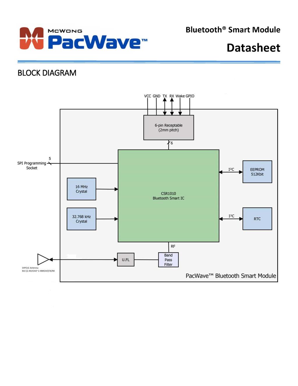
1 Pacwave Bluetooth Smart (BLE) Module FEATURES Built in CSR μenergy CSR1010 Bluetooth Smart (v4.1) chipset +7.5dBm Maximum RF Transmit Output Power 92.5dBm RF Receive Sensitivity RSSI Monitoring Built in Switch mode Power Supply 512Kbit (65,536 x 8) EEPROM Real Time Clock (RTC) and Calendar UART Communication Wake up Interrupt GPIO Operating voltage: 3.3V ~16mA Active Transmit/Receive ~1mA Idle Mode <5uA Sleep Mode Size: 24mm x 28.5mm U.FL Connector Bluetooth Smart Specification v4.2 Ready FCC and Bluetooth SIG Pending RoHS Compliant DESCRIPTION The PacWave Bluetooth Smart module fully supports single mode Bluetooth Low Energy operation. The module receives its power from a host that provides 3.3V and ground to the 6 pin receptacle, and also communicates with the host via the UART on the same 6 pin receptacle. The two additional pins provide a wake up interrupt input and a general purpose input/output (GPIO). The module can be programmed using the open sockets. The RTC can be used for timekeeping and scheduling of activities McWong International Inc. // 1921 Arena Blvd, Sacramento, CA // (916) // McWongInc.com
2
 Pin Name I/O Type Description 1 SCLK I/O Programming/Debug SPI clock 2 CS")
3 PIN DESCRIPTIONS J1 (6 pin Receptacle) Pin Name I/O Type Description 1 VDD Input Power supply to module 2 GND GND Power supply Ground 3 RX Input UART Interface Receive 4 TX Output UART Interface Transmit 5 GPIO I/O General Purpose Input/output 6 WAKE Input Module wake up interrupt signal J2 (Programming/Debug socket) Pin Name I/O Type Description 1 SCLK I/O Programming/Debug SPI clock 2 CS Input Programming/Debug SPI chip select 3 MOSI Input Programming/Debug SPI MOSI 4 MISO Output Programming/Debug SPI MISO 5 SPI_EN Input Programming/Debug SPI Enable J3 (Off module Antenna Connector) Pin Name I/O Type Description 1 Ext. Ant. I/O U.FL (male) Off module antenna connector
4 ELECTRICAL SPECIFICATIONS Absolute Maximum Ratings Rating Min Max Unit Input supply voltage V I/O supply voltage V Other terminal voltages VSS 0.4 VCC V Storage Temperature C Recommended Operating Conditions Rating Min Max Unit Input supply voltage V I/O supply voltage V Operating temperature range C Digital Terminals Voltage Levels Min Max Unit Voltage input logic level low x VCC V Voltage input logic level high 0.7 x VCC VCC V Input rise/fall time 25 ns Voltage output logic level low 0.4 V Voltage output logic level high 0.75 x VCC V Output rise/fall time 5 ns ESD Protection Condition Class Max Rating Human body model contact discharge V (all pins) Charged device model contact discharge III 500V (all pins)
5 ELECTRICAL SPECIFICATIONS (cont.) Current Consumption (T ambient = 25 C) Mode Description Total Typical Current at 3V Dormant All functions are shutdown. Toggle WAKE pin to wake them up. <900nA Hibernate Everything off except for the sleep clock and VCC pads. <1.9μA Deep Sleep VCC pads, sleep clock, RAM, digital circuits, SMPS are on. 2.2ms wake up time. <5μA Idle MCU idling ~1mA RX/TX Active RF active 3V peak current General Characteristics Model Name WCM 01 Product Description Bluetooth Smart (BLE) wireless module Dimensions (a) 24mm x 28.5mm x 3.75mm (W*L*T) Weight 3g ± 0.1g (a) Thickness = 4.67mm when including the height of the 6 pin receptacle.
 6.05mm 3.")

6 MECHANICAL DATA (cont.) 2.00mm 4.00mm 2.00mm (pitch) 6.05mm 3.56mm NOTE: For best performance, the module should be connected near or on the outside edge of the host PCB with nothing underneath the antenna portion.
 interface dedicated to the host for communication to and from the module.")

7 APPLICATION INFORMATION HOST INTERFACE The module incorporates one Universal Asynchronous Receiver/Transmitter (UART) interface dedicated to the host for communication to and from the module. Also available to the host is one General Purpose Input/Output (GPIO) and a WAKE interrupt input used to wake up the module from a low power sleep mode. The host supplies 1.8V 3.6VDC and ground to power the module.
 Wire Length 150mm Material of Radiator Cu Connector IPEX (U.FL, female) S.W.R <= 2.0 @ 2400 2500MHz Gain (Typical) 2.")
8 EXTERNAL ANTENNA The module is certified for use only with the following FCC approved antenna. FCC Approved Antenna Specifications Manufacturer Shenzhen Taida Century Technology Co., Ltd Part Number 1012 Type Whip Straight (Wire) Wire Length 150mm Material of Radiator Cu Connector IPEX (U.FL, female) S.W.R <= MHz Gain (Typical) MHz // Peak Gain Impedance 50 Ohm Polarization Linear Operating Temperature 30 C to +85 C Storage Temperature 30 C to +85 C NOTE: Use of other antenna types or the same type with a higher gain is not allowed without additional testing and FCC approval.
9 FEDERAL COMMUNICATIONS COMMISSION (FCC) STATEMENTS The PacWave Module complies with Part 15 of the United States of America FCC rules and regulations. The Original Equipment Manufacturer (OEM) must comply with the FCC certification requirements Any changes or modifications made to the module without the manufacturer s approval could void the user s authority to operate the module (b) This equipment has been tested and found to comply with the limits for a Class B digital device, pursuant to part 15 of the FCC rules. These limits are designed to provide reasonable protection against harmful interference in a residential installation. This equipment generates, uses and can radiate radio frequency energy and, if not installed and used in accordance with the instructions, may cause harmful interference to radio communications. However, there is no guarantee that interference will not occur in a particular installation. If this equipment does cause harmful interference to radio or television reception, which can be determined by turning the equipment off and on, the user is encouraged to try to correct the interference by one or more of the following measures: Reorient or relocate the receiving antenna. Increase the separation between the equipment and receiver. Connect the equipment into an outlet on a circuit different from that to which the receiver is connected. Consult the dealer or an experienced radio/tv technician for help. PLEASE NOTE THE MODULE OPERATION IS SUBJECT TO THE FOLLOWING TWO CONDITIONS: 1. This device may not cause harmful interferences. 2. This device must accept any interference received, including interference that may cause undesired operation. RADIATION EXPOSURE STATEMENT This equipment complies with FCC radiation exposure limits set forth for an uncontrolled environment. End users must follow the specific operating instructions for satisfying RF exposure compliance. This transmitter must not be co located or operating in conjunction with any other antenna or transmitter, and the end product must have a separation distance of at least 20mm from all persons. With the documented max output power the module meets the FCC SAR Exemption to comply with any applicable RF exposure requirements in its final configuration.
10 ORIGINAL EQUIPMENT MANUFACTURER (OEM) NOTES The OEM must certify the final end product to comply with unintentional radiators (FCC Sections and ) before declaring compliance of the final product to Part 15 of the FCC rules and regulations. Integration into devices that are directly or indirectly connected to AC lines must add with Class II Permissive Change. The OEM must comply with the FCC labeling requirements. If the module s label is not visible when installed, then an additional permanent label must be applied on the outside of the finished product which states: Contains transmitter module FCC ID: ZZOWCM 01. Additionally, the following statement should be included on the label and in the final product s user manual: This device complies with Part 15 of the FCC Rules. Operation is subject to the following two conditions: (1) This device may not cause harmful interferences, and (2) this device must accept any interference received, including interference that may cause undesired operation. The module is limited to installation in mobile or fixed applications. Separate approval is required for all other operating configurations, including portable configuration with respect to Part and different antenna configurations. A module or modules can only be used without additional authorizations if they have been tested and granted under the same intended end use operational conditions, including simultaneous transmission operations. When they have not been tested and granted in this manner, additional testing and/or FCC application filing may be required. The most straightforward approach to address additional testing conditions is to have the grantee responsible for the certification of at least one of the modules submit a permissive change application. When having a module grantee file a permissive change is not practical or feasible, the following guidance provides some additional options for host manufacturers. Integrations using modules where additional testing and/or FCC application filing(s) may be required are: (A) a module used in devices requiring additional RF exposure compliance information (e.g., MPE evaluation or SAR testing); (B) limited and/or split modules not meeting all of the module requirements; and (C) simultaneous transmissions for independent collocated transmitters not previously granted together. This Module is full modular approval, it is limited to OEM installation ONLY. Integration into devices that are directly or indirectly connected to AC lines must add with Class II Permissive Change. (OEM) Integrator has to assure compliance of the entire end product incluld the integrated Module. Additional measurements (15B) and/or equipment authorizations (e.g Verification) may need to be addressed depending on co-location or simultaneous transmission issues if applicable. (OEM) Integrator is reminded to assure that these installation instructions will not be made available to the end user of the final host device.
BluetoothMesh ModuleDatasheet
 BluetoothMesh ModuleDatasheet (WS_D02_8266_V2.2) Shenzhen WE SMART Electronics Co., Ltd Website:www.we smart.cn Mailbox:business@we smart.cn Address:7th FL,Bldg 2B,Wu tong dao industrial park,hangkong
User's Manual. WM-294-V2 WLAN 11n USB module (1T1R) Version: 1.2. 晶訊科技股份有限公司 CC&C Technologies, Inc. Version 1.2 1
 Version: 1.2. 晶訊科技股份有限公司 CC&C Technologies, Inc. Version 1.2 1") User's Manual WM-294-V2 WLAN 11n USB module (1T1R) Version: 1.2 Manufacturer Version 1.2 1 Revision History Version Issue date Reason for revision 1.0 Mar. 02, 2015 First edition 1.1 Oct. 05, 2016 Modify
User's Manual WM-294-V2 WLAN 11n USB module (1T1R) Version: 1.2 Manufacturer Version 1.2 1 Revision History Version Issue date Reason for revision 1.0 Mar. 02, 2015 First edition 1.1 Oct. 05, 2016 Modify
RF Engine Model RF100 Part Numbers: RF100PC6 and RF100PD6 Document Revision v1.0
 DATA SHEET RF Engine Model RF100 Part Numbers: RF100PC6 and RF100PD6 Document Revision v1.0 2011 Synapse, All Rights Reserved All Synapse products are patented or patent pending Specifications are subject
Meshreen MS5168 ZigBee Module MS5168-Mxx series USER MANUAL FCC ID :2AC2E-68M04
 Meshreen MS5168 ZigBee Module MS5168-Mxx series USER MANUAL FCC ID :2AC2E-68M04 Meshreen DS MS5168 / info@meshreen.com 1 Content 1. Introduction... 3 1.1 Variants... 3 2. Specification... 4 2.1 Pin configurations...
Manual Unihan UPWL6580
 Manual Unihan UPWL6580 Federal Communications Commission Statement This device complies with FCC Rules Part 15. Operation is subject to the following i. This device may not cause harmful interference,
WML- 46### User Manual
 Page 1 of 6 WML- 46### User Manual The purpose of this manual is to explain correct way how to integrate module WML- 46### to the end product. It includes procedures that shall assist you to avoid unforeseen
VDBTLE24. BTLE Single Mode Module with USB. Description. Applications
 BTLE Single Mode Module with USB VDBTLE24 Description VDBTLE24, Bluetooth low energy single mode module is a single mode Bluetooth 4.0 device targeted for low power sensors and accessories. VDBTLE24 offers
U S E R S M A N U A L
 U S E R S M A N U A L C2104001 BCM 43224 WiFi Card Contents SECTION ONE: INTRODUCTION... 3 1. INTRODUCTION... 3 1.1 SCOPE... 3 1.2 FUNCTION... 3 1 2 PRODUCT SPECIFICATION... 4 2.1 HARDWARE SPECIFICATION...
User Manual WHM520V. 1. Introduction. 2. Feature
 User Manual 1 Introduction The module is wireless audio module based on AV5100 The AV5100 is 5GHz wireless audio SoC (System-on-chip), optimized for building point to multi-point digital wireless audio
Manual Unihan UPWL6024
 Manual Unihan UPWL6024 Federal Communications Commission Statement This device complies with FCC Rules Part 15. Operation is subject to the following i. This device may not cause harmful interference,
Manual Unihan UPWL6025
 Manual Unihan UPWL6025 Federal Communications Commission Statement This device complies with FCC Rules Part 15. Operation is subject to the following i. This device may not cause harmful interference,
CRUX II/BTGPS USER GUIDE. Model:D1598
 CRUX II/BTGPS USER GUIDE Model:D1598 0 Federal Communication Commission Interference Statement This equipment has been tested and found to comply with the limits for a Class B digital device, pursuant
TM14-2.4G/R6014FS/R608FS Radio Control Instruction Manual
 TM14-2.4G/R6014FS/R608FS Radio Control Instruction Manual INTRODUCTION Thank you for purchasing a FutabaR digital proportional R/C system. In order for you to make the best use of your system and to use
User Manual. Product Name:tablet Model Name:TM800A740M Brand Name:NuVision. Manufacture:Shenzhen Vastking Electronic Co.,LTD.
 User Manual Product Name:tablet Model Name:TM800A740M Brand Name:NuVision Manufacture:Shenzhen Vastking Electronic Co.,LTD. FCC Warning This device complies with part 15 of the FCC
802.11n, 2.4G 1T1R Wireless LAN PCI Express Half Mini Card
 802.11n, 2.4G 1T1R Wireless LAN PCI Express Half Mini Card WN6605LH Realtek RTL8191SE User s Manual Ben J. Chen 3/4/2010 Federal Communication Commission Interference Statement This equipment has been
SENTRY. AC410x family + BT-V2.0. User s Manual
 SENTRY AC410x family + BT-V2.0 SENTRY TABLE OF CONTENTS 1. INTRODUCTION AND BLOCK DIAGRAM... 2 1.1. GENERAL INTRODUCTION... 2 1.2. BLOCK DIAGRAM... 3 2. MAIN FEATURES AND APPLICATION... 4 2.1. SYSTEM KEY
SIM800C_User Manual_ V1.00
 SIM800C_User Manual_ V1.00 SIM900-DS Document Compliance Information FCC Compliance Statement: This device complies with Part 15 of the FCC Rules. Operation is subject to the following two conditions:
PTT- Z or PTT-U PUSH-TO-TALK Specification
 Federal Communication Commission Interference Statement This equipment has been tested and found to comply with the limits for a Class B digital device, pursuant to Part 15 of the FCC Rules. These limits
System Requirements: D-Link Systems, Inc.
 System Requirements: Minimum System Requirements: CD-ROM Drive Computers with Windows, Macintosh, or Linux-based operating systems Installed Ether net Adapter Internet Explorer version 6.0 or Netscape
Nebulae Module V2. Datasheet. System Level Solutions, Inc. (USA) Murphy Avenue San Martin, CA (408)
 Murphy Avenue San Martin, CA (408)") Nebulae Module V2 Datasheet, Inc. (USA) 14100 Murphy Avenue San Martin, CA 95046 (408) 852-0067 http://www.slscorp.com Module Version: 1C Document Version: 1.4 Document Date: Copyright 2018,, Inc. (SLS)
Nebulae Module V2 Datasheet, Inc. (USA) 14100 Murphy Avenue San Martin, CA 95046 (408) 852-0067 http://www.slscorp.com Module Version: 1C Document Version: 1.4 Document Date: Copyright 2018,, Inc. (SLS)
SRWF-1022 Series Low Power Wireless Transceiver Module User Manual
 SRWF-1022 Series Low Power Wireless Transceiver Module User Manual Page 1 of 6 I. SRWF-1022 SRWF-1022 User Manual (V1.1) SRWF-1022, the low-power wireless transceiver module is used as the wireless command
Transponder Reader TWN4 MultiTech 3 Quick Start Guide
 Transponder Reader TWN4 MultiTech 3 Quick Start Guide Rev. 1.0 1. Introduction The transponder reader TWN4 is a device for reading and writing RFID transponders. There are different versions of TWN4 devices
GX_W60_V3.5 WIFI Video module Mnaual
 GX_W60_V3.5 WIFI Video module Mnaual W60 Tel:86-755-26066032 Fax:26002892 Web site:www.netopsun.com 1 / 8 1 summary 1.1 overview of the whole W60_WIFI module is the latest introduction of crown Asahi Technology
Datasheet LT1110 Wireless Module. Version 3.1
 A Version 3.1 REVISION HISTORY Version Date Notes Approver 3.0 13 Jan 2014 Separated into two separate docs: Hardware Integration Guide and User Guide. Marked as Rev 3.0 to match User Guide. Sue White
ZigBee SE2.0 - IEEE OASIS RF MODULE
 FEATURES +20dBm (100mW) Nominal Transmit Power Dual Antenna Ports for Indoor Applications Very small 25mm x20mm x 1.7mm form factor Long range-up to 1000 meters LoS MKW22D512V 50MHz 32 bit ARM Cortex M4
SP14808 Bluetooth Module User s Guide
 SP14808 Bluetooth Module User s Guide An Integrated 2.4GHz Bluetooth SMART Compliant Transceiver Module TDK Corporation Thin Film Device Center SESUB BU Revision FC 2015.1.1 TDK Corporation 2013-2014 1
CCR24T CCR24R. User s Guide WIRELESS TRANSMITTER SYSTEM WARRANTY SERVICE CARD WARRANTY CARD
 WARRANTY SERVICE CARD WARRANTY CARD PRODUCT NAME Wireless Transceiver System PERIOD MODEL NAME CCR24GEN YEAR PURCHASE DATE.. 200_ From the date of WARRANTY PERIOD.. 200_ purchase. CUSTOMER S ADDRESS :
MPRF01 Wireless 5uA Inductive Proximity Sensor RF System
 System Description; The MPRF01 is a simple ready to use Wireless Inductive. No programming is required; just insert 2, (1.5V) AA batteries into the Transmitter module. The RF receiver module is connected
APM 6998 WiFi Module Manual
 Host Revision Information APM 6998 WiFi Module Manual Host Hardware Revision Host Module Driver Version Module Hardware Revision T3x Rev D1 v8.1.4.4 001E Host PCB Design Guidelines The following guidelines
Blue Point Engineering
 Overview Blue Point Instruction Board 2-CH Boards, Terminal Block and Ribbon Cable I Type: RF Radio (315 MHz) 1-2 Channels (FCC Part 15 Compliant Components). Operating Voltage: 6-15 VDC @ 1 Amp (Wall
ORiNOCO AP-4000MR-LR and AP-4900MR-LR Access Points Safety and Regulatory Compliance Information
 IMPORTANT! Visit http://support.proxim.com for the latest safety and regulatory compliance information for this product. ORiNOCO AP-4000MR-LR and AP-4900MR-LR Access Points Safety and Regulatory Compliance
RFM-CSB-2. Features of the Module include: The RFM-CSB-2 module
 The RFM-CSB-2 module The RFM-CSB-2 is a class 2 Bluetooth 4.0 module for integration into lighting fixtures, LED drivers or other lighting controls. The module contai a powerful 32 bit ARM CortexTM microcontroller
User Manual. 1. Introduction. 2. Features
 1. Introduction User Manual AMPAK Technology would like to announce a low-cost and low-power consumption module which has all of the WiFi and Bluetooth functionalities. The highly integrated module makes
SIM800 User Manual. 1. SIM800 Description Summarize Feature
 User Manual 1. Description 1.1. Summarize designed by SIMCom is a quad band module which supports GSM/GPRS. The baseband circuit is based on MTK and RF circuit is based on RFMD. It works at quad bands------gsm850,
Meshreen MS516x ZigBee Module MS516x-Mxx series
 Meshreen MS516x ZigBee Module MS516x-Mxx series Meshreen DS-MS5168 / info@meshreen.com 1 Content 1. Introduction... 3 1.1 Variants... 3 2. Specification... 4 2.1 Pin configurations... 5 2.2 Pin Assignment...
5.8G Wireless Audio Transceiver/Receiver Module DWHP83
 5.8G Wireless Audio Transceiver/Receiver Module DWHP83 1. Module dimensions and layout 2. Antenna info Brand: EDIFIER Antenna type: PCB Max Peak gain: 5.36 dbi 3. Feature: DARR83 Wireless Audio Processor
SPZB260-PRO. ZigBee module. Features. Description. Applications
 ZigBee module Features Integrated 2.4 GHz, IEEE 802,15,4-compliant transceiver: 3 dbm nominal TX output power -95 dbm RX sensitivity + 5 dbm in boost mode RX filtering for co-existence with IEEE 802.11g
BT50 Datasheet. Amp ed RF Technology, Inc.
 BT50 Datasheet Amp ed RF Technology, Inc. 1 BT50 Product Specification BT50 features Bluetooth features FCC, IC, CE & Bluetooth certified Bluetooth v4.1 Smart Ready Class 1 radio Range up to 80m LOS 1.5Mbps
INSTALLATION AND OPERATING MANUAL
 INSTALLATION AND OPERATING MANUAL FOR RBDA-PCS-1/25W-90-A INDOOR REPEATER TABLE OF CONTENTS PARAGRAPH PAGE NO BDA OVERVIEW 3 BDA BLOCK DIAGRAM DESCRIPTION 3 FCC INFORMATION FOR USER 3 BDA BLOCK DIAGRAM
Link Mobile Gateway User Guide A ProVIEW System Component
 A ProVIEW System Component Omni-ID office locations: US UK China India Southeast Asia Germany 1. CONTENTS 1. Introduction... 3 About this Document... 3 Related Products... 3 Regulatory Approvals... 4 Certifications...
Quick Start Guide. Antenna Alignment Tool AIMWLLR0-35. QSG rev 7 AIMWLLR0-35 [NRB-0200] QSG.indd 1
![Quick Start Guide. Antenna Alignment Tool AIMWLLR0-35. QSG rev 7 AIMWLLR0-35 [NRB-0200] QSG.indd 1](/thumbs/86/94268876.jpg "Quick Start Guide. Antenna Alignment Tool AIMWLLR0-35. QSG rev 7 AIMWLLR0-35 [NRB-0200] QSG.indd 1") Quick Start Guide Antenna Alignment Tool AIMWLLR0-35 QSG-00097 rev 7 AIMWLLR0-35 [NRB-0200] QSG.indd 1 Welcome This quick start guide is designed to familiarize you with the features and use of the NetComm
Quick Start Guide Antenna Alignment Tool AIMWLLR0-35 QSG-00097 rev 7 AIMWLLR0-35 [NRB-0200] QSG.indd 1 Welcome This quick start guide is designed to familiarize you with the features and use of the NetComm
USER MANUAL MODEL: BM-162
 USER MANUAL MODEL: BM-162 Parents Unit: A. Name Power ON/OFF Key Music Key PTT Key Volume - Key Microphone Power & Low battery indicator LCD display Volume + Key Night Light and torch Key Speaker -Belt
LoRa Module Datasheet
 LoRa Module Datasheet Part Number: MLORA100 rev 001 Zenseio LLC Updated: August 2016 Table of Contents Table of Contents Functional description LORA MODULE OVERVIEW FEATURES BLOCK DIAGRAM Interfaces PIN
INSTALLATION MANUAL FOR SAL SERIES WIRELESS CLOCKS SPECIFICATIONS
 INSTALLATION MANUAL FOR SAL SERIES WIRELESS CLOCKS SPECIFICATIONS Time base: Quartz Power input: Battery (2 D cell) : Part # SAL-1BS-12R-0 95 135 VAC / 60 Hz: Part # SAL-1BS-12R-1 7 28 VAC / 60 Hz: Part
SOM i.mx6. Regulation Information. Simple. Robust. Computing Solutions. Rev 1.1
 SOM i.mx6 Regulation Information Rev 1.1 Simple. Robust. Computing Solutions SolidRun Ltd. 7 Hamada st., Yokne am Illit, 2495900, Israel www.solid-run.com 1 Page Document revision 1.1 24052018 SolidRun
JetWave WIFI Module Industrial 2.4G n 2.4G/ 5G ac mpcie WIFI module
 JetWave WIFI Module Industrial 2.4G 802.11n 2.4G/ 5G 802.11ac mpcie WIFI module User Manual V1.0 Aug. 2016 JetWave WIFI Module User Manual Copyright Copyright 2016 all rights reserved. No part of this
PCK43302, PCK MHz Penta series Keyring Remotes with Frequency Hopping
 PCK43302, PCK43304 433MHz Penta series Keyring Remotes with Frequency Hopping FEATURES Small Size keyring remote with 2 or 4 buttons Dual Coding System, dip switch and encrypted code Transmission on 5
Round shape, white case with 3M adhesive sticker, including 2pcs ER12450 battery and industrial package, special for indoor location, RoHS
 Beacon / ibeacon / MiniBeacon FCC Statement This equipment has been tested and found to comply with the limits for a Class B digital device, pursuant to Part 15 of the FCC Rules. These limits are designed
User Manual. MITSUMI WiFi Module MODEL DWM-W081
 Page 1 of 7 User Manual MITSUMI WiFi Module MODEL DWM-W081 The purpose of this manual is to explain correct way how to integrate module DWM-W081 to the end product. It includes procedures that shall assist
Connected Cooler Radio. Quick Start Guide
 Connected Cooler Radio Quick Start Guide Table of Contents 1. GETTING STARTED... 5 1.1 UNPACKING INFORMATION... 5 1.2 INTRODUCTION... 5 2. PORTS AND LED INDICATORS... 6 2.1 PORTS... 6 2.2 LED INDICATORS...
Bluetooth Sports Headphones
 Bluetooth Sports Headphones Model:4R0M FCC ID:S4L4R0M USER GUIDE Charging 1 2 Pairing 5 sec. 1 2 On / Off Volume up 3 sec. Next track Play / Pause 2 sec. Volume down Previous track 2 sec. Fitting R Wearing
HY737 Walkie talkie for kids
 HY737 Walkie talkie for kids ANTENNA SWITCH, VOLUME KNOB RED STATUS LIGHT MIC SPEAKER WWW.THEIPAR.CC WILLIAMWANG18@OUTLOOK.COM FCC ID: 2AJEM-HY737 ANTENNA ANTENNA SWITCH, VOLUME KNOB BELT BUCKLE PUSH TO
SWL-2900U User Guide REV 0.9. Summary. SWL-2900U DatasheetUser Guide. Samsung Electro-Mechanics
 User Guide SWL-2900U User Guide REV 0.9 Samsung Electro-Mechanics 2007-12-26 Summary This document describes the general User-Guide of SWL-2900U IEEE 802.11b/g Wireless LAN USB 2.0 module. 2007 Samsung
Hangzhou Delan Technology Co., Ltd
 Doc Name DL2103B-QCA4004 User s Manual Doc No. DL-YJ-20150516-001 Version 1.1.2 Prepare: Biao Sun Check : Approve: Prepare Date: Mar. 28, 2016 Check Date: Approve Date: DL2103B-QCA4004 User s Manual Hangzhou
Table of Contents. Mounting Diagram.. Wiring Information.. Setting the STR 1000 as a Repeater or a Transmitter. STR 1000 Frequently Asked Questions..
 STR 1000 Series Repeater Installation Manual (V 3.0) Table of Contents MOUNTING Mounting Diagram.. Page 2 WIRING INFORMATION Wiring Information.. Page 3 Setting the STR 1000 as a Repeater or a Transmitter.
Manufacturer. Version 1.4
 Product Specifications WM-888E WLAN n USB module (TR) Version:.4 Manufacturer CC&C Technologies, Inc. Version.0..2.3.4 Revision History Issue date Reason for revision Oct. 4, 202 First edition Nov.5,202
802.11a/n/b/g/ac WLAN Module AMB7220
 AboCom 802.11a/n/b/g/ac WLAN Module AMB7220 User s Manual FCC Certification Federal Communication Commission Interference Statement This equipment has been tested and found to comply with the limits for
Guide to FCC/Canada Regulations for. Low Power Modular Wireless Transmitters For North America
 Guide to FCC/Canada Regulations for Low Power Modular Wireless Transmitters For North America Provided by Elite Electronic Engineering, Inc. 1516 Centre Circle, Downers Grove, IL 60515 630-495-9770 www.elitetest.com
Alchemy Systems L.P. SISTEM Radio Frequency Remote Control(8015-2R) & receiver(8015-2b) User Guide. Version: 2.4. Prepared by: Carlos A Acosta
 & receiver(8015-2b) User Guide. Version: 2.4. Prepared by: Carlos A Acosta") Alchemy Systems L.P. 8015 Shoal Creek Blvd., Suite 100 Austin, TX 78757 tel: 512-637-5100 fax: 512-637-5168 www.alchemysystems.com Alchemy Systems L.P. SISTEM Radio Frequency Remote Control(8015-2R) &
Alchemy Systems L.P. 8015 Shoal Creek Blvd., Suite 100 Austin, TX 78757 tel: 512-637-5100 fax: 512-637-5168 www.alchemysystems.com Alchemy Systems L.P. SISTEM Radio Frequency Remote Control(8015-2R) &
User Manual. 1. Introduction. 2. Features
 1. Introduction User Manual AMPAK Technology would like to announce a low-cost and low-power consumption module which has all of the Wi-Fi functionalities. The highly integrated module makes the possibilities
Blue Point Engineering Inc.
 nc. Wireless Radio Control of Puppets Setup Overview RF Control C Hardware Setup Overview Servo No.1 Servo No.2 Control Signal Line RX8-ch1,2 Servo Board WZ-12 RX8-ch3,4 Servo Board WZ-12 Power Line DC
900 MHz. Frequency Hopping RS-485 Master/Slave auto-sensing radio interface.
 MDR210A-485 900 MHz. Frequency Hopping RS-485 Master/Slave auto-sensing radio interface. Black Box Corporation Lawrence, PA - http://www.blackbox.com - Ph 877-877-BBOX - Fax 724-746-0746 Table of Contents
3X3 2.4/5GHz 11ac minipcie Radio Model: WLE900VX
 3X3 2.4/5GHz 11ac minipcie Radio Model: WLE900VX Revision:1.03 IL Date: 2014,11,10 Features Qualcomm-Atheros QCA9890, Reference Design 2.4GHz max 19dBm & 5GHz max19dbm output power (per chain) IEEE 802.11ac
IMPORTANT: THIS DEVICE MUST BE PROFESSIONALLY INSTALLED. READ AND UNDERSTAND ALL INSTRUCTIONS BEFORE BEGINNING INSTALLATION.
 INSTALLATI INSTRUCTIS Model: RB-G-K10 IMPORTANT: THIS DEVICE MUST BE PROFESSIALLY INSTALLED. READ AND UNDERSTAND ALL INSTRUCTIS BEFORE BEGINNING INSTALLATI. The Miller Edge RBand Monitored Gate Edge Transmitter/Receiver
SX-SDWAG a/b/g SDIO Module User Manual
 SX-SDWAG 802.11a/b/g SDIO Module User Manual 2008 Silex Technology America, Inc. All rights reserved. September, 2008 Silex Technology America SPECIFICALLY DISCLAIMS THE IMPLIED WARRANTIES OF MERCHANTABILITY
Reference Design v1.0
 Reference Design v1.0 The goal of this document is to provide application guidance in the integration of either an 868-MHz or 915-MHz PCB notch antenna, depending on the module type, into a product design.
OEM KEYFOB TRANSMITTER DATA GUIDE
 CMD-KEYX-XXX OEM KEYFOB TRANSMITTER DATA GUIDE DESCRIPTION The Linx CMD-KEYX-XXX Remote Command keyfob is ideal for generalpurpose remote control and command applications. The unit has been precertified
RM24100D. Introduction. Features. 2.4GHz 100mW RS232 / RS485 / RS422 DSSS Radio Modem (IEEE compliant) Operating Manual English 1.
 Operating Manual English 1.") RM24100D 2.4GHz 100mW RS232 / RS485 / RS422 DSSS Radio Modem (IEEE 802.15.4 compliant) Operating Manual English 1.09 Introduction The RM24100D radio modem acts as a wireless serial cable replacement and
RM24100D 2.4GHz 100mW RS232 / RS485 / RS422 DSSS Radio Modem (IEEE 802.15.4 compliant) Operating Manual English 1.09 Introduction The RM24100D radio modem acts as a wireless serial cable replacement and
EE1941XS/EN1941XS One-Way Serial RF Module Installation and Operation Manual
 EE1941XS/EN1941XS One-Way Serial RF Module Installation and Operation Manual 1 Overview EchoStream RF modules are designed to be easily interfaced with your electronic remote application controller (RAC).
Operating Distance An operating distance (in conjunction with our GLR27 series receivers) of 350 metres is possible.
 of 350 metres is possible.") ELSEMA 27MHz HAND HELD GIGALINK TRANSMITTERS GLT2700, GLT2701, GLT2702, GLT2703, GLT2704 and GLT2708 Features Over 4 billion code combinations Can program any number of transmitters to a receiver High
ELSEMA 27MHz HAND HELD GIGALINK TRANSMITTERS GLT2700, GLT2701, GLT2702, GLT2703, GLT2704 and GLT2708 Features Over 4 billion code combinations Can program any number of transmitters to a receiver High
BK8000L Bluetooth Audio SoC User Guide
 BK8000L Bluetooth Audio SoC User Guide F-6688 Brand:XINZHONGXIN FCC ID:2AG94F-6688 Shenzhenshi Xinzhongxin Technology Co., Ltd. Page 1 of 14 BK8000L Datasheet Contents 1. General Description...4 1.1. Features...4
USER MANUAL Universal Gateway U9921-GUV (P/N: 40994G-01)
") USER MANUAL Universal Gateway U9921-GUV (P/N: 40994G-01) 2012 DAVID CLARK COMPANY INCORPORATED Cautions and Warnings READ AND SAVE THESE INSTRUCTIONS. Follow the instructions in this installation manual.
USER MANUAL Universal Gateway U9921-GUV (P/N: 40994G-01) 2012 DAVID CLARK COMPANY INCORPORATED Cautions and Warnings READ AND SAVE THESE INSTRUCTIONS. Follow the instructions in this installation manual.
Innovation First, Inc. RS MHz Robot Controller User Manual
 RS-422 900 MHz Robot Controller User Manual 10.31.2006 www.innovationfirst.com Page 2 Table of Contents 1. Robot Controller Overview... 3 2. Installation... 3 3. Theory of Operation... 3 4. FCC / Industry
SP GHz Digital Wireless Speakers. User s Manual. Please read before using the equipment. Please visit for details.
 SP1390 2.4GHz Digital Wireless Speakers User s Manual Please read before using the equipment. Please visit www.promowide.com for details. INTRODUCTION This 2.4G digital wireless speakers system uses latest
Hi-Fi Shelf System *MFL * SIMPLE MANUAL
 ENGLISH SIMPLE MANUAL Hi-Fi Shelf System Please read this manual carefully before operating your set and retain it for future reference. To view the instructions of advanced features, visit http://www.lg.com
CDR-915 Data Radio Module INTEGRATOR S GUIDE
 CDR-915 Data Radio Module Coyote DataCom, Inc. 3941 Park Drive, Suite 20-266, El Dorado Hills, CA 95762 Tel. 916-933-9981 Fax 916-913-0951 www.coyotedatacom.com TABLE OF CONTENTS General Information and
RN-41-SM. Class 1 Bluetooth Socket Module. Features. Applications. Description. Block Diagram. rn-41sm-ds 9/9/2009
 RN-41-SM www.rovingnetworks.com rn-41sm-ds 9/9/2009 Class 1 Bluetooth Socket Module Features Socket module 3/5V DC TTL I/O Fully qualified Bluetooth 2.1/2.0/1.2/1.1 module Bluetooth v2.0+edr support Low
IMPORTANT: READ AND UNDERSTAND ALL INSTRUCTIONS BEFORE BEGINNING INSTALLATION
 INSTALLATI INSTRUCTIS Model: RB-G-K10 IMPORTANT: READ AND UNDERSTAND ALL INSTRUCTIS BEFORE BEGINNING INSTALLATI The Miller Edge RBand Monitored Gate Edge Transmitter/Receiver system is intended to provide
Blue Point Engineering Inc.
 Engineering Inc. ireless Radio Control of Puppets Setup Overview RF Control C Pointing the ay to Solutions! Hardware Setup Overview Page 1 Servo No.1 Servo No.2 Control Signal Line RX8ch1,2 Servo Board
RM24100A. *Maximum transmit power output levels and local radio frequency regulator bodies must be obeyed in the country of operation.
 RM24100A 2.4GHz 100mW RS232 / RS485 / RS422 DSSS Radio Modem (IEEE 802.15.4 compliant) Operating Manual English 1.02 Introduction The RM24100A radio modem acts as a wireless serial cable replacement and
DNT90MCA DNT90MPA. Low Cost 900 MHz FHSS Transceiver Modules with I/O
 - 900 MHz Frequency Hopping Spread Spectrum Transceivers - Direct Peer-to-peer Low Latency Communication - Transmitter Power Configurable to 40 or 158 mw - Built-in 0 dbi Chip Antenna - 100 kbps RF Data
IMPORTANT: THIS DEVICE MUST BE PROFESSIONALLY INSTALLED READ AND UNDERSTAND ALL INSTRUCTIONS BEFORE BEGINNING INSTALLATION
 INSTALLATI INSTRUCTIS Models: RB-G-K10, RB-TX10 IMPORTANT: THIS DEVICE MUST BE PROFESSIALLY INSTALLED READ AND UNDERSTAND ALL INSTRUCTIS BEFORE BEGINNING INSTALLATI The Miller Edge RBand Monitored Gate
Power Genius XL User Manual rev 10.
 Power Genius X User Manual rev 10. 1/23 Table of Contents 0. Important notice...3 1. Unpacking...5 1.1. Front Panel...5 1.2. Back Panel...6 1.3. BCD/PTP connector pinout...8 2. Using with Radios...9 2.1.
Complete 2.4 GHz RF Transceiver Module with Built-In RFDP8 Application Protocol Part Numbers RFD21733, RFD21735, RFD21737, RFD21738, RFD21739
 Complete 2.4 GHz RF Transceiver Module with Built-In Application Protocol Part Numbers,,,, Optional Configuration For use with External Antenna 15mm x 15mm (0.600 inch x 0.600 inch) / is a complete, READY-TO-USE
Electronic Emission Notices
 Electronic Emission Notices - - - - - - - - - - - - - - - - - - - - - - - - - - - - - - - - - - - - - - - - - - - - - - - - - - - - - - The following information refers to the Lenovo Active pen. Federal
Remote Control Outlets Operating Instructions
 Remote Control Outlets Operating Instructions - FOR INDOOR OR OUTDOOR USE - IMPORTANT SAFEGUARDS Signal Word Definitions NOTE: These are general definitions only; all may not pertain to the actual product
Door/Window Sensor User Manual HKWL DWS02W
 Door/Window Sensor User Manual HKWL DWS02W 1. PRODUCT OVERVIEW HKWL DWS02W is a Wi Fi wireless Door/Window sensor, you can monitor the status of your door/window in real time through your smart phone.
VT-CC2530-Z1 Wireless Module. User Guide
 Wireless Module User Guide V-CHIP MICROSYSTEMS Co. Ltd Address: Room 612-613, Science and Technology Service Center Building, NO.1, Qilin Road, Nanshan District, Shenzhen, Guangdong TEL:0755-88844812 FAX:0755-22643680
Focus Iris Manual Ver 1.1
 Focus Iris Manual Ver 1.1 Preston Cinema Systems 1659 Eleventh Street Santa Monica CA 90404 tel 310 453 1852 fax 310 453 5672 www.prestoncinema.com Table of Contents 1. Description 2. Operation 3. Specifications
Technical Description. Wireless Automation Input/Output Module WDIO100
 Technical Description Wireless Automation Input/Output Module Please note the following Target group This description is intended for the use of trained specialists in electrical installation and control
swarm bee LE Development Kit User Guide
 Application Note Utilizing swarm bee radios for low power tag designsr Version Number: 1.0 Author: Jingjing Ding swarm bee LE Development Kit User Guide 1.0 NA-14-0267-0009-1.0 Document Information Document
SF C-Series. 900 MHz Wireless Switch Follower/Remote Control Receiver (with On-Board 10-Amp Relays) Typical Applications
 Typical Applications") Long Range Wireless Applications 900 MHz Wireless Switch Follower/Remote Control Receiver (with On-Board 10-Amp Relays) The SF900C Series Remote Control/Switch Followers are a twoway system designed to
Long Range Wireless Applications 900 MHz Wireless Switch Follower/Remote Control Receiver (with On-Board 10-Amp Relays) The SF900C Series Remote Control/Switch Followers are a twoway system designed to
Mini Hi-Fi System *MFL * SIMPLE MANUAL
 ENGLISH SIMPLE MANUAL Mini Hi-Fi System Please read this manual carefully before operating your set and retain it for future reference. To view the instructions of advanced features, visit http://www.lg.com
User Manual. Snap AS02-PAR38NAE26 LED Bulb. Outdoor HD Security Camera with LED Floodlight
 User Manual Snap AS02-PAR38NAE26 LED Bulb Outdoor HD Security Camera with LED Floodlight Features Simply installation, and no wires required 1080P High-Quality live stream & recording Advanced motion detection
M508 GPS Tracking Device
 M508 GPS Tracking Device (GPS+GPRS+GSM) Product Manual Edition 1.3 Copyright 10 th Oct., 2009 GATOR GROUP CO.,LTD. All rights reserved. http://www.gatorcn.com China Printing ADD: 312# Ansheng Building,Xixiang
Characteristic Sym Notes Minimum Typical Maximum Units Operating Frequency Range MHz. RF Chip Rate 11 Mcps RF Data Rates 1, 2, 5.
 RFM Products are now Murata products. Small Size, Light Weight, Low Cost 7.5 µa Sleep Current Supports Battery Operation Timer and Event Triggered Auto-reporting Capability Analog, Digital, Serial and
Catalog
 Catalog 1. Description... - 3-2. Features... - 3-3. Application... - 3-4. Electrical specifications...- 4-5. Schematic... - 4-6. Pin Configuration... - 5-7. Antenna... - 6-8. Mechanical Dimension(Unit:
802.11g Wireless Sensor Network Modules
 RFMProducts are now Murata Products Small Size, Integral Antenna, Light Weight, Low Cost 7.5 µa Sleep Current Supports Battery Operation Timer and Event Triggered Auto-reporting Capability Analog, Digital,
EE1941/EN1941/EN One-Way Binary RF Module Installation and Operation Manual
 EE1941/EN1941/EN1941-60 One-Way Binary RF Module Installation and Operation Manual 1 Overview EchoStream RF modules are designed to be easily interfaced with your electronic remote application controller
RN-41. Class 1 Bluetooth Module. Features. Applications. Description. Block Diagram. DS-RN41-V3.
 RN-41 www.rovingnetworks.com DS--V3.1 11/13/2009 Class 1 Bluetooth Module Features Fully qualified Bluetooth 2.1/2.0/1.2/1.1 module Bluetooth v2.0+edr support Postage stamp sized form factor, 13.4mm x