BFoxCon Manual. Version 0.2 October 30, 2017
|
|
|
- Clara Garrett
- 5 years ago
- Views:
Transcription

1 Overview The Byonics BFoxCon is a radio controller board designed to pair with a Baofeng UV-5R to create a transceiver for hidden transmitter hunts, also called T-hunts, foxhunts, and ARDF. It mounts on the back of the radio, connects to the SP/MIC jack, and is powered by the radio s battery. The UV-5R was chosen because it is a low cost, easy to find radio that can transmit either 3W or 6W, but the BFoxCon can be adapted for use with any hand held (HT) or mobile radio. It can be remote controlled via DTMF and configured via DTMF or a computer, and can be adjusted with many tones, durations, and duty cycles. BFoxCon Manual Version 0.2 October 30, 2017 The transmissions consist of a looping sequence as follows: an off the air pre-tones delay to support multiple sequenced transmitters a looping tones transmission is user configurable and played during the majority of the hunt a Morse code message or ID to legally identify the transmitter an off the air delay to allow DTMF control, lower duty cycle, or other transmitters to be heard In addition to the sequence above, it also supports: an initial delay to start the transmitter when the hider is not present a total runtime to limit the length of the hunt Battery Wiring The BFoxCon can be ordered either fully assembled and ready to connect to the UV-5R, or as a PCB requiring the user to solder the interface wiring to the battery and the SP/MIC jack. The BFoxCon can by powered by the UV-5R battery, or any 7V - 12V supply when interfacing to another radio. There are 2 ways to power the BFoxCon from the UV-5R battery. The first requires the BL-5L 7.4V 3800mah extended battery. This battery has a charging jack near the top that can also be used to power external devices. Using a cable with a 1.7mm x 4mm right angle plug, cut the wire to about 1½ long (2¼ when including the plug), strip and tin ⅛, and solder to the tops of the + & - pads on the PCB, and not inserted through the pad holes. The plug center conductor is connected to +. The BFoxCon can be powered by plugging this cable into the BL-5L battery. The other way to power will work with any battery, but requires soldering to the radio itself, and could damage the radio if done incorrectly. With the battery removed from the radio, there are 4 spring terminals exposed. The 2 nearest the SP/MIC jack are the + contacts. Solder a 2 24 AWG wire to the tip of the one terminal nearest the SP/MIC jack. Be careful not to let the soldering iron touch the terminal for more than about 1 second at a time, or the plastic case will melt. Solder the other end of the wire to the top of the + pad on the PCB, and not inserted through the pad hole. Do not connect to

2 the - terminal or pad. Possibly file a small notch in the corner of the radio so the wire is not crimped when the battery is connected. The BFoxCon can be powered by plugging in the SP/MIC plug which will provide the ground connection. Audio Wiring The UV-5R typically ships with a ear/mic headset, and this cable can be used to wire the BFoxCon to the SP/MIC jack. These headsets can be purchased for about $1. Cut the wire to about 3 long (4¾ when including the plug), strip off ⅜ of the outer black insulation to expose the 4 wires inside. These wires each have an enamel polymer film insulation that should be melted off. Create a large bead of solder on the tip of the soldering iron, and hold the last ⅛ of each wire in this bead for about 5 seconds. This should melt off the insulation and tin the wire. The four wires can then be soldered to the tops of G, R, P, & T pads on the PCB, and not inserted through the pad holes. The colors of the wires are not universal, so use an ohmmeter to determine which color goes to each pad. The audio and power cables can be zip tied together to help strain relief each other. Plug Contact Function Pad 2.5mm sleeve Ground G 2.5mm tip Receive Audio R 3.5mm sleeve Push To Talk P 3.5mm ring Transmit Audio T If using the BFoxCon with a radio other than the UV-5R, just connect each of the pads to the appropriate radio connection. If using a radio that doesn t have a PTT connection, such as a Yaesu or Icom HT, leave that connection out, and short the J1 jumper with a solder blob. The R8 pot can be used to adjust the transmit audio level. Computer Configuration The BFoxCon settings can be configured via DTMF tones or with the a USB serial cable and the Windows MicroFoxConfig program version 1.9 or later. The cables and software are available from PL2303 USB drivers can be found at The configuration program can only be used within 3 seconds powering the BFoxCon. The default settings that appear when the configuration program is started are recommended for a basic hunt with the BFoxCon transmitting tones for 15 seconds, and then a Morse
3 code ID. It then will stop transmitting, and repeats every 30 seconds. The only setting users must change is the Morse Code ID text to be their assigned amateur radio callsign. The TX Frequency, RX Frequency, and Disable RX settings are not applicable to the BFoxCon, as the RF frequencies are set on the connected radio. The Calibration option is available in the Config program but not via DTMF commands. It can be used to tweak the long term timing of a BFoxCon. Positive calibration numbers make the unit run faster. If you determine that the BFoxCon is running 0.03% slow, set the calibrate to +0.03% to correct. The BFoxCon will work with a TTL or RS232 serial cable. The cable must be connected to a 1x4 0.1 pitch header in the following order: Pin Function Typical Color 1 (square pad) Ground black 2 Serial In green 3 +3V to +5V power red 4 Serial Out white After installing the USB drivers, inserting the USB cable, and setting the desired options in the configuration program, select the connected cable COM port, connect the 1x4 plug cable to the J2 PCB holes such that ground/black is in the square pad, press Read Version, then Write Config to apply the settings. The serial cable will power the BFoxCon, and the program can only communicate to the BFoxCon within the first 3 seconds of it getting power. Note: When using a TTL serial cable, the BFoxCon will not operate until it receives the first serial command from the config program, so do not be surprised when the LED doesn t flash on powerup. DTMF Configuration and Control The BFoxCon can be remote controlled and configured by sending DTMF tones from either the connected radio, or a separate radio on the same frequency. The transmitting radio needs to be able to send all 16 DTMF tones : 0-9, *, #, and A-D. On some radios, the A-D keys may not be labeled. The receiver volume may need to be adjusted for best DTMF decoding. Sending DTMF 3 and watching the LED is a good way to find a suitable volume level. The LED will flash quickly while DTMF tones are being decoded and at a medium speed during configuration. The BFoxCon can be DTMF locked to prevent other DTMF controls or configuration until it received the unlock code, default Note: Some UV-5R radios have a bug in the firmware that send a DTMF 0 when the DTMF D key (EXIT) is pressed. When this is the case, a separate radio with a functioning DTMF D key will be required to activate the Lock DTMF function.
4 DTMF Control Codes DTMF Configuration Codes DTMF tone Function 1 Start transmission 2 Toggle transmission 3 Stop transmission D Lock DTMF control DTMF configuration is divided into 3 command sets. The A commands take 6 DTMF digits, the B commands take 4 DTMF digits, and the C commands are a variable length, and terminate with the # tone. A1mmss A2mmss A3mmss A4hhmm A5hhmm A6xxxx A7xxxx Set the pre-tones off the air delay to mm minutes and ss seconds. The default is off, and can be set with A Set the tones duration to mm minutes and ss seconds. The default is 15 seconds, and can be set with A Set the loop time to mm minutes and ss seconds. This should be set to at least the duration of the tones, plus the time to send the morse ID. The default is 30 seconds, and can be set with A Set the initial delay to hh hours and mm minutes. The default is off, and can be set with A Set the total runtime to hh hours and mm minutes. The default is off, and can be set with A Set the transmit frequency to 14x.xxx MHz. Power must be cycled for the new value to take effect. The default is MHz and can be set with A Set the receive frequency to 14x.xxx MHz. It doesn t need to be the same as the transmit frequency. Power must be cycled for the new value to take effect. The default is MHz and can be set with A A8xxxx Set the 4 digit unlock code. The default is 1234 and can be set with A B1xx Set tone duration in 5 ms units. This controls the tone sequence speed. The default is 50 ms and can be set with B110. B2xx Set morse code speed in words per minute. Valid settings are between 03 and 31 wpm. The default is 20 wpm and can be set with B220. B3xx B4xx Set morse tone to tone code xx. This sets the audio frequency of the morse code ID. Refer to the DTMF Tone Codes table below. The default code is 24 (784 Hz) and can be set with B324. Set flags bits to xx. This sets various on/off options. The possible flags codes are: 1 for Random tones, instead of the C2 sequence. 2 for Random tone speed, instead of the B1 setting.
5 4 for Random morse tone, instead of the B3 setting. 8 for Auto-Start right after powerup, rather than waiting for a DTMF 1 or for Disable LED, to make the transmitter more difficult to visually see. To set more than 1 flag, just add the codes together, for example, to enable random tone speed and auto-start (2+8=10), send B410. The default flags are just auto-start and can be set with B408. C1 xx xx xx.. # C2 xx xx xx.. # Set the morse code message/callsign. Use the DTMF Morse Codes table below. To keep the transmissions legal, a valid amateur radio callsign should be included in this message. Each character is entered as a 2 digit code and the message is terminated with a #. Maximum message length is 60 characters. For example, to set to N6BG enter C #. C2 xx xx xx.. # - Set the tone sequence. This sets tones that are repeated during the tone sequence. Each note is entered as a 2 digit code from the chart below and the sequence is terminated with a #. Maximum tone sequence length is 160 notes. The default tone sequence can be set with C #. DTMF Morse Codes code char code char code char code char code char code char code char code char 00 space 07 G 14 N 21 U SK 51, 01 A 08 H 15 O 22 V 29 / $ 52 : 02 B 09 I 16 P 23 W AS 53 ; 03 C 10 J 17 Q 24 X BT 04 D 11 K 18 R 25 Y ( 57? 05 E 12 L 19 S 26 Z ! 48 ) 06 F 13 M 20 T AR 59 _ SK, AS, and AR are procedural signs. DTMF Tone Codes code note freq code note freq code note freq code note freq code note freq 01 silence 11 F # E D C A G F D # C # A # G # F # E D B A G F D # C A # G # F # E C # B A G F D C A # G # F # D # C # B A G E D C A # G # F D # C # B

6 LED The LED will show the various states of the BFoxCon. It flashes 3 times on powerup. If a TTL serial connection is found, it flashes 3 more times (but only after the first serial data is received). If it is jumpered for a system restore, it will flash 3 more times. The LED can be disabled to make the fox more difficult to find. The list below shows the LED meaning during operation. LED on Solid - Transmitting LED Fast Flash (20Hz) - Receiving DTMF LED Medium Flash (5 Hz) - Receiving configuration tones LED Slow Flash (1 Hz) - In a transmit sequence but currently off the air. LED Off - Not in a sequence Restore The BFoxCon can restored to factory settings by temproarily shorting 2 pins marked RST and applying power. There will be 3 extra LED flashes to show the settings have been restored. Starting the config program, and writing all the default values is an additional way to restore settings. Notes If the assigned COM port is not showing in the config software, it can be manually entered, or the COM port can be changed with Windows Device Manager. Disabling the FIFO buffer in the Com Port settings may improve serial communication. We recommend leaving a note with the transmitter identifying it as an Amateur Radio, and listing a contact telephone number. These days, your transmitter may cause undue alarm if found by a member of the public and outside agencies are contacted. PCB
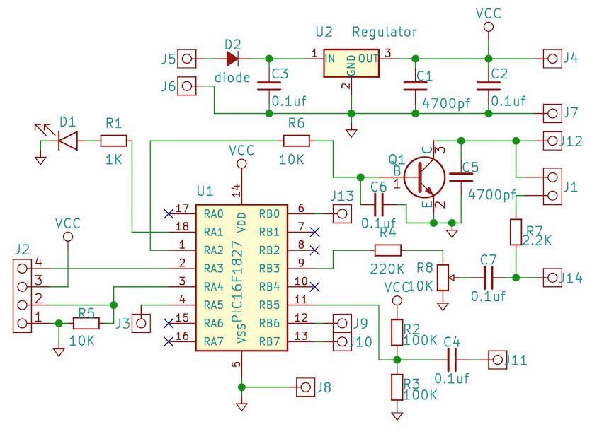
7 Schematic
MicroFox2 Manual. Version 0.5 August 28, 2017
 Overview The Byonics MicroFox2 (MF2) is a small, 500mW, frequency agile 2-meter transceiver designed for hidden transmitter hunts, also called T-hunts, foxhunts, and ARDF. It is based on the Byonics MicroFox-PicCon,
Micro Fox PicCon Manual
 Micro Fox PicCon Manual Version 0.61 The Micro Fox PicCon (MF PC) is a 700mW fox hunting/hidden transmitter hunt transceiver. It can be configured and remotely controlled via DTMF tones, and also be configured
PicCon Owner's Manual Version 2.06
 PicCon Owner's Manual Version 2.06 http://www.byonics.com/piccon - 1 - Overview... 2 Acknowledgments... 2 Construction... 3 Schematic... 3 Parts List... 3 Printed Circuit Board... 4 Case... 4 Assembly
BeeLine TX User s Guide V1.1c 4/25/2005
 BeeLine TX User s Guide V1.1c 4/25/2005 1 Important Battery Information The BeeLine Transmitter is designed to operate off of a single cell lithium polymer battery. Other battery sources may be used, but
PicCon. Radio Transmitter Controller User s Manual. User s Manual version 1.0 Firmware version 1.0 Hardware version 1.0
 PicCon Radio Transmitter Controller User s Manual User s Manual version 1.0 Firmware version 1.0 Hardware version 1.0 Byon Garrabrant, N6BG 1150 N. Harding St. Orange, CA 92867 (714) 538-0203 byon@netcom.com
BandMaster V Manual. Installation
 BandMaster V Manual Installation Installing and configuring the BM-5 BandMaster V is a simple process. All the configuration process is done from the front panel. Installation and configuration steps are
Chapter 15: Serial Controlled (HF) Radio Support
 Radio Support") 15-1 Chapter 15: Serial Controlled (HF) Radio Support This section describes the controller's interface for serial controlled radios. Most such radios are for the HF bands, but some such as the FT-736
15-1 Chapter 15: Serial Controlled (HF) Radio Support This section describes the controller's interface for serial controlled radios. Most such radios are for the HF bands, but some such as the FT-736
ICS REPEATER CONTROLLERS
 ICS REPEATER CONTROLLERS BASIC CONTROLLER USER MANUAL INTEGRATED CONTROL SYSTEMS 1076 North Juniper St. Coquille, OR 97423 Email support@ics-ctrl.com Website www.ics-ctrl.com Last updated 5/07/15 Basic
C S Technology Ltd. cstech.co.uk. DTMF decoder kit with relay output, opto coupled input & Morse transpond.
 C S Technology Ltd cstech.co.uk DTMF decoder kit with relay output, opto coupled input & Morse transpond. Our DTMF Opto decoder kit has one relay output offering clean contacts, and one Opto coupled input
TABLE OF CONTENTS. Keypad Programming Manual 1
 TABLE OF CONTENTS How To Program Radios...2 Keypad Programming...2 A. Navigation...3 1. Group Parameters (CH 00)...4 2. Channel Parameters (CH 01 - CH20)...4 3. Global Parameters (GRP 00)...5 B. Group
LNR Precision Mountain Topper MTR-4B and MTR-5B REV 2.0 User Manual for use with versions with 16 x 2 display.
 LNR Precision Mountain Topper MTR-4B and MTR-5B REV 2.0 User Manual for use with versions with 16 x 2 display. Four band MTR 4B shown Overview: The Mountain Topper Rigs are designed to be a very small,
B & D Enterprises 1P repeater controller pg 1 INTRODUCTION:
 B & D Enterprises 1P repeater controller pg 1 INTRODUCTION: The 1P is a basic repeater controller. The controller uses low power devices and stores all commands and system status in non-volatile EE prom.
G3P-R232. User Manual. Release. 2.06
 G3P-R232 User Manual Release. 2.06 1 INDEX 1. RELEASE HISTORY... 3 1.1. Release 1.01... 3 1.2. Release 2.01... 3 1.3. Release 2.02... 3 1.4. Release 2.03... 3 1.5. Release 2.04... 3 1.6. Release 2.05...
TI RigExpert. User s manual. USB Transceiver Interface
 TI-5000 RigExpert USB Transceiver Interface User s manual . Table of contents Introduction Operating the TI-5000 Front and rear panels Transceiver and computer connection Updating the firmware Annexes
CONNECT SYSTEMS INCORPORATED 5321 Derry Ave., Suite B Agoura Hills, CA FLEX SERIES UNIVERSAL CONTROLLER
 CONNECT SYSTEMS INCORPORATED 5321 Derry Ave., Suite B Agoura Hills, CA 91301 Phone (805) 642-7184 Fax (805) 642-7271 FLEX SERIES UNIVERSAL CONTROLLER FLEX IIIA CTCSS COMMUNITY TONE PANEL User s Instruction
G1SLE Mk2 Repeater Controller Programming.
 G1SLE Mk2 Repeater Controller Programming. The 89C55WD or equivalend microprocessor is supplied with G1SLE repeater controller software pre-loaded in flash memory. The various parameters such as callsign
WJ9J DTMF and Remote Base Controller. Version
 WJ9J DTMF and Remote Base Controller Version 2016-12-19 1 This manual Copyright 2012 by Andy Zorca, WJ9J, All Rights Reserved. Hardware Notice The code contained in the 16F628A or 16F88 Microchip device
instruction manual for Open LRS New Generation
 instruction manual for Open LRS New Generation Table of contents 1. Important warnings 2. Hardware Overview 3 2.1 DTF UHF 4 Channel 4 2.2 HobbyKing RX 5 3. Instructions 3.1 Basic functions 6 3.2 Flashing
Will only send Status Text until GPS Lock! Format of Status Text: Status Text Altitude Volts Temp X AVRT5 (version)
") AP510 / AVRT5 Documentation Based upon firmware and configuration version(s) 20151031 (development build) Author: Mark Cheavens KC5EVE Version: 20151031 1.1 Quick Start: Power Button Uses: Firmware Update
AP510 / AVRT5 Documentation Based upon firmware and configuration version(s) 20151031 (development build) Author: Mark Cheavens KC5EVE Version: 20151031 1.1 Quick Start: Power Button Uses: Firmware Update
AT-5888UV Programming Software for the AnyTone AT-5888UV
 AT-5888UV Programming Software for the AnyTone AT-5888UV Memory Channel Functions Memory Types Memories Limit Memories Hyper Memory 1 Hyper Memory 2 Receive Frequency Transmit Frequency Offset Frequency
Connecting the FCC-2 to the Hendricks DC Kits Bob Okas, W3CD
 Connecting the FCC-2 to the Hendricks DC Kits Bob Okas, W3CD This is an application note that describes how you can connect the NorCal FCC-1/2 combination to the DC kits. It involves a few extra components
Introduction. Control Functions
 Introduction The MFJ-441 SlimLine Econo Keyer with Memory is a microprocessor controlled keyer that provides iambic key operation and dot-and-dash memory to make sending perfect code easier. It has tunable
JEM Radio II Operation Guide. Manual P/N M Victor Place Colorado Springs, Colorado
 JEM Radio II Manual P/N M09999-999 2115 Victor Place Colorado Springs, Colorado 80915 800.284.0399 www.jemcom.com Table of Contents Display... 3 Channel Entry... 4 Shortcuts... 4 Text Messages... 4 Buttons...
BAND DECODER and CONTROLLE R. Accessibility Upgrade and Operating Instructions
 ELE CRAFT KRC2 BAND DECODER and CONTROLLE R Accessibility Upgrade and Operating Instructions Revision A, March 4, 2004. Copyright 2004, Elecraft; All Rights Reserved Introduction The KRC2 Accessibility
RigExpert TI-7 USB Transceiver Interface User s manual
 RigExpert TI-7 USB Transceiver Interface User s manual Please read this manual before attempting to use the RigExpert TI-7 device. - - 2 - Table of contents 1. What is a RigExpert TI-7?... 4 2. Specifications...
ICS REPEATER CONTROLLERS
 ICS REPEATER CONTROLLERS SINGLE M USER MANUAL INTEGRATED CONTROL SYSTEMS 1613 Bonnie Avenue Dixon, IL 61021 Voice 815-284-6963 Fax 815-288-0718 Website www.ics-ctrl.com Last updated 01/08/2005 Single M
CAT-700B Repeater Controller Computer Automation Technology, Inc
 CAT-00B Repeater Controller Computer Automation Technology, Inc N.W. st Avenue, Suite Fort Lauderdale, Florida 0 Phone: () 8- Fax: () 88-8 Internet: http://www.catauto.com Table of Contents Chapter Page.
Portable Repeater Controller. Instruction Manual for firmware version 1.0
 Portable Repeater Controller Instruction Manual for firmware version 1.0 1. Table of Contents 1. TABLE OF CONTENTS... 2 2. INTRODUCTION... 3 2.1 OVERALL DESCRIPTION... 3 2.2 WARNINGS... 4 2.3 CONFIGURATION
SV613 USB Interface Wireless Module SV613
 USB Interface Wireless Module SV613 1. Description SV613 is highly-integrated RF module, which adopts high performance Si4432 from Silicon Labs. It comes with USB Interface. SV613 has high sensitivity
DTMF decoder kit with 8 outputs and Morse transpond. 8 output DTMF decoder with 4 on board BT47 style 12V relays and 4 open collector outputs
 DJS Electronics Ltd cstech.co.uk DTMF decoder kit with 8 outputs and Morse transpond Features 8 output DTMF decoder with 4 on board BT47 style 12V relays and 4 open collector outputs Each output can be
TECHNICAL NOTES MT-4 Radio Systems TN182 Battery Level Reporting and Remote P25 Test Tone
 Battery Level Reporting is a method of activating a repeater remotely to have it transmit a signal that reports the battery voltage level over RF. The Remote P25 Test Tone is a remotely activated Standard
Step by Step Building PJ meter ARDF Receiver Kit. CRKITS.COM August 5, 2013
 Step by Step Building PJ-80 80-meter ARDF Receiver Kit CRKITS.COM August 5, 2013 What is ARDF? ARDF is the abbreviation of Amateur Radio Direction Finding, or so called Fox Hunting. If you are looking
Mobililinkd TNC2 User Guide
 Mobililinkd Thank you for purchasing your new Mobilinkd TNC2 Battery-powered Bluetooth TNC. This TNC is designed to suit all aspects of the Amateur Radio community. It is ready to plug in and go with easy
NHRC-7 User Guide. Software Version: User Guide Version: 2004-Dec-24
 NHRC-7 User Guide Software Version:. User Guide Version: 004-Dec-4 Copyright Notice Copyright 00, 004 by NHRC LLC This document contains proprietary information that is the confidential property of NHRC
ID Timer / Annunciator
 NØXAS ID Timer / Annunciator ID-O-Matic The ID-O-Matic is a single chip ID timer/annunciator intended for Amateur Radio and other applications. Several modes of operation make it suitable for use in the
Microphone audio, from the MFJ-1278B to your transmitter. Ground, audio and PTT common. Push-to-talk, to allow the MFJ-1278B to key your transmitter.
 Computer interfacing, covered in the previous chapter, is only half the interfacing task. The other half is connecting your MFJ-1278B to your radios. MFJ-1278B Radio Ports Interfacing the MFJ-1278B to
EVDP610 IXDP610 Digital PWM Controller IC Evaluation Board
 IXDP610 Digital PWM Controller IC Evaluation Board General Description The IXDP610 Digital Pulse Width Modulator (DPWM) is a programmable CMOS LSI device, which accepts digital pulse width data from a
CAT-260 Repeater Controller Computer Automation Technology, Inc
 CAT-260 Repeater Controller Computer Automation Technology, Inc 7378 W. Atlantic Blvd. #239 Margate, Florida 33063 Phone: (954) 978-6171 Fax: (561) 465-5891 Internet: http://www.catauto.com Table of Contents
FoxRex 144. RigExpert. Made in the Ukraine. User s manual. ARDF Receiver 144MHz
 FoxRex 144 ARDF Receiver 144MHz RigExpert Made in the Ukraine User s manual . Table of contents Introduction Specifications Getting started Charging the battery Switching the receiver on/off Receiver s
DragonLink Advanced Transmitter
 DragonLink Advanced Transmitter A quick introduction - to a new a world of possibilities October 29, 2015 Written by Dennis Frie Contents 1 Disclaimer and notes for early release 3 2 Introduction 4 3 The
ATP-5189 Programming Software for the Anytone AT-5189
 for the Anytone AT-5189 Memory Types Memories Limit Memories VFO Receive Frequency Transmit Frequency Offset Frequency Offset Direction Channel Spacing Name Tone Mode CTCSS Rx CTCSS DCS Memory Channel
SoftRock v5.0 Builder s Notes. December 12, Building a QSD Kit
 SoftRock v5.0 Builder s Notes December 12, 2005 Building a QSD Kit Be sure to use a grounded tip soldering iron in building the QSD board. The soldering iron needs to have a small tip, (0.05-0.1 inch diameter),
CAT-700 Repeater Controller
 CAT-700 Repeater Controller Computer Automation Technology, Inc. 4631 N.W. 31st Avenue, Suite 142 Fort Lauderdale, Florida 33309 Phone: (954) 978-6171 Fax: (561) 488-2894 Internet: http://www.catauto.com
AMERITRON RCS-12 AUTOMATIC ANTENNA SWITCH
 AMERITRON RCS-12 AUTOMATIC ANTENNA SWITCH INSTRUCTION MANUAL PLEASE READ THIS MANUAL BEFORE OPERATING THIS EQUIPMENT! 116 Willow Road Starkville, MS 39759 USA 662-323-8211 Version 3B Printed in U.S.A.
WJ9J Repeater Accessory Board. Version
 WJ9J Repeater Accessory Board Version 2015-05-18 1 This manual Copyright 2013-2017 by Andy Zorca, WJ9J, All Rights Reserved. Hardware Notice The code contained in the 16F88 Microchip device is copy protected.
Release 0.3. Rolling Thunder Technical Reference Manual
 Release 0.3 Rolling Thunder Technical Reference Manual INTRODUCTION Introduction Rolling Thunder consists of one transmitter in a Paragon 3 Rolling Thunder equipped locomotive and one Rolling Thunder receiver
HT-1A Dual Band CW QRP Transceiver. Kit Building Instructions
 HT-A Dual Band CW QRP Transceiver Kit Building Instructions Rev B, July 8, 08 Designed by BD4RG Exclusively distributed by CRKITS.COM and its worldwide distributors Join the group http://groups.io/g/crkits
Confident proficiency to accomplish this task is MADNITORY, DO NOT ATTEMPT & get help from someone else if you are unsure of your abilities.
 1 Yaesu DR1X easy remote reset modification DE- K5BLS Supplies: Commspec TS-64 CTCSS or DCS-23 *DCS Decoder board SPDT 12 Automotive relay 30A SPDT Relay Harness Heat shrink tubing Wire ties 3M Automotive
Pacific Antenna Simple Keyer Kit
 Pacific Antenna Simple Keyer Kit Specifications and Features: Speed range of 5 to 30 wpm Operates in either iambic A or B mode, with B being the default 2 message memories Tune and Beacon modes Built on
CAT-800 Repeater Controller Computer Automation Technology, Inc
 CAT-800 Repeater Controller Computer Automation Technology, Inc 7378 W. Atlantic Blvd. #239 Margate, Florida 33063 Phone: (954) 978-6171 Fax: (561) 465-5891 Internet: http://www.catauto.com Table of Contents
Signal Lights Demonstration Video Time Duration: - 38 sec. Use the right hand mouse button for video control.
 Tip: - Working Turntable Signals and Cabin Lights using Gold TC7.0F1 and Above Hi All, At long last I completed the project to have working signals and cabin lights on my turntable. This is a record of
Pion and Simon Electronics. PSE Repeater Controller User s Guide
 Pion and Simon Electronics PSE-508-3 Repeater Controller User s Guide Document Version 1.0 Revised November 21, 2011 Pion & Simon Electronics LLC PO Box 23651, Tigard, OR 97281 (503) 545-4732 www.pionsimon.com
Kenwood TH-G71 Protocol Specification
 Kenwood TH-G71 Protocol Specification This document describes the serial commands used to program and control the TH-G71 radio via its serial port. Some of this data was initially based on information
KENWOOD SKY COMMAND SYSTEM
 KENWOOD SKY COMMAND SYSTEM Operation Manual KENWOOD COMMINICATIONS CORPORATION KENWOOD COMMUNICATIONS CORPORATION This operation manual is used for the KENWOOD SKY COMMAND SYSTEM (hereinafter referred
VBRC 4. Radio Communicator. Installer Manual
 VBRC 4 Radio Communicator Installer Manual 17 December 2014 CONTENT 1. INTRODUCTION...3 2. SYSTEM STRUCTURE...3 3. SYSTEM PROGRAMMING WITH PC SOFTWARE...5 4. TROUBLESHOOTING...6 5. FIRMWARE UPGRADE...7
CONNECT SYSTEMS INCORPORATED 1802 Eastman Ave., Suite 116 Ventura, Ca FLEX III UNIVERSAL CONTROLLER
 CONNECT SYSTEMS INCORPORATED 1802 Eastman Ave., Suite 116 Ventura, Ca. 93003 Phone (805) 642-7184 Fax (805) 642-7271 FLEX III UNIVERSAL CONTROLLER INTERCONNECT DISPACH SYSTEM AA User s Instruction Manual
BAND AIDE AUTOMATIC BAND DECODER
 BAND AIDE AUTOMATIC BAND DECODER 1. Features Overview The Top Ten Devices Band Aide is an accessory that attaches to your radio (or computer), decodes the band data provided by the radio, and provides
PART TWO $10 TNC CONSTRUCTION PROJECT AUDIO BOARD AND FINAL ASSEMBLY November, 2016
 PART TWO $10 TNC CONSTRUCTION PROJECT AUDIO BOARD AND FINAL ASSEMBLY November, 2016 Mark the side of the board that will have connections to the RADIO, and the side that will have connections to the COMPUTER.
Morse ID Timer / Annunciator
 Morse ID Timer / Annunciator The ID-O-Matic II kit is a microprocessor based, ID timer/annunciator with repeater control functions suitable for Amateur Radio and other applications. Several modes of operation
ATP-588 Programming Software for the Anytone AT-588
 for the Anytone AT-588 Memory Channel Functions Memory Types Memories Limit Memories VFO Receive Frequency Transmit Frequency Offset Frequency Offset Direction Channel Spacing Name Tone Mode CTCSS Rx CTCSS
IMPORTANT: READ AND UNDERSTAND ALL INSTRUCTIONS BEFORE BEGINNING INSTALLATION
 INSTALLATI INSTRUCTIS Model: RB-G-K10 IMPORTANT: READ AND UNDERSTAND ALL INSTRUCTIS BEFORE BEGINNING INSTALLATI The Miller Edge RBand Monitored Gate Edge Transmitter/Receiver system is intended to provide
SoftRock v6.0 Builder s Notes. May 22, 2006
 SoftRock v6.0 Builder s Notes May 22, 2006 Be sure to use a grounded tip soldering iron in building the v6.0 SoftRock circuit board. The soldering iron needs to have a small tip, (0.05-0.1 inch diameter),
FOD Transmitter User s Guide
 FOD Transmitter User s Guide Rev 5, 05/21/2014 AVID Technologies, Inc. FOD Transmitter User s Guide Page 2 General Description The AVID FOD (Foreign Object Detection) Transmitter is a standard WPC Qi V1.1
Disable Windows Sounds
 9/28/2017 - K3CT Disable Windows Sounds Users may want to disable the Windows Sounds so none of the Windows OS sounds are transmitted on the radio. Install the Icom Drivers, Select COM port, Disable Power
INSTALLATION AND CONNECTIONS Section 2
 STLLTION ND CONNECTIONS Section Unpacking - ntenna jumper cable connection - Selecting a location - Rack mounting handle attachment - Grounding -3 ntenna connection -3 CF (Compact Flash) memory card -3
Introduction 1. Download socket (the cable plugs in here so that the GENIE microcontroller can talk to the computer)
") Introduction 1 Welcome to the magical world of GENIE! The project board is ideal when you want to add intelligence to other design or electronics projects. Simply wire up your inputs and outputs and away
Introduction 1 Welcome to the magical world of GENIE! The project board is ideal when you want to add intelligence to other design or electronics projects. Simply wire up your inputs and outputs and away
INDEX...2 INTRODUCTION...3 IMPORTANT NOTES...3 INSTALLING THE SOFTWARE...3 ST-965 PROGRAMMING SOFTWARE...6
 ST-965 VX/D SMARTRUNK II & SMARTRUNK XPRESS Logic board Programming Software 2.9e User s Guide Revision R2.9 10/10/2008 INDEX INDEX...2 INTRODUCTION...3 IMPORTANT NOTES...3 INSTALLING THE SOFTWARE...3
CONNECT SYSTEMS INCORPORATED 1802 Eastman Ave., Suite 116 Ventura, Ca FLEX SERIES UNIVERSAL CONTROLLER
 CONNECT SYSTEMS INCORPORATED 1802 Eastman Ave., Suite 116 Ventura, Ca. 93003 Phone (805) 642-7184 Fax (805) 642-7271 FLEX SERIES UNIVERSAL CONTROLLER FLEX IIIA LTR CONTROLLER AND COMMUNITY TONE PANEL User
Installation... 3 Installing The Radio... 3 Ignition Noise Interference... 4 Antenna... 4 External Speaker... 4 Public Address...
 TABLE OF CONTENTS CHAPTER 1 Specifications.............................................. 2 PAGE BIG RIG SERIES S 1 MOD PW R 20 0 3 SW R 40 1 5 5 60 1.5 7 10 2 9 20 80 3 30 +20 40 50 +40 100% MAX db +60
User manual Ascom SE550 Transceiver
 User manual Ascom SE550 Transceiver Document Revision history Revision Date Changes 1.5 2 nd August 2004 Initial release 1.6 6 th August 2004 Typographical changes and better description of operation.
JUMA PA1000 Linear Amplifier User Manual
 Linear Amplifier User Manual User Manual Version 1.38 for Firmware V1.17 or newer Page 1 of 15 Congratulations! We are happy that you have selected the linear amplifier. You will find it easy to use. Enjoy
ALAN 777 PMR 446 Radio Set User manual
 ALAN 777 PMR 446 Radio Set User manual The all new ALAN 777 represents the very latest and most advanced technology currently available on the PMR446 and LPD market. With its stylish lines and modern design,
Installation Manual Console Integration System
 Installation Manual Console Integration System Table of Contents Kit Contents... 2 Overview... 3 Installation Instructions... 3 Typical Installation Wiring Diagram... 4 Configuring the Network Bridge...
Pair of PMR446 Two-Way Personal Radios Model: TP391
 Pair of PMR446 Two-Way Personal Radios Model: TP391 USER MANUAL MANUALE D USO MANUEL DE L UTILISATEUR BEDIENUNGSANLEITUNG MANUAL DE USUARIO MANUAL DO USUÁRIO HANDLEIDING BRUKSANVISNING P/N:086L004722-016
SoftRock v6.0 Builder s Notes. April 6, 2006
 SoftRock v6.0 Builder s Notes April 6, 006 Be sure to use a grounded tip soldering iron in building the v6.0 SoftRock circuit board. The soldering iron needs to have a small tip, (0.05-0. inch diameter),
Barrett 950 HF SSB Transceiver Operating and Installation Manual
 Barrett 950 HF SSB Transceiver Operating and Installation Manual Barrett Communications BCM95000/1 Head office: European office: Barrett Communications Pty Ltd Barrett Europe Limited 10 Port Kembla Drive,
Code Master. Model CWR-610E OPERATING INSTRUCTIONS
 Code Master Model CWR-610E OPERATING INSTRUCTIONS CONTENTS RATING... 3 DESCRIPTION OF PANELS... 5 METHOD OF USE Preparation... 7 Reception of CW... 7 Code interpretable range and word space... 7 Reception
Reference for UV-5R Menus by Jim Unroe - KC9HI 2-April-2014
 Long Name / Description / / Notes / 0 SQL Carrier Squelch Mutes the speaker of the transceiver in the absence of a strong signal. VHF squelch is either OFF or ON. UHF squelch is either OFF or one of 9
Introduction to FLDIGI Karl Frank, W2KBF
 Introduction to FLDIGI Karl Frank, W2KBF Purpose To Provide Fair Lawn ARC members with an Introduction to FLDIGI; Demonstrate Use of FLMSG to send an errorfree text message on an ICS form. (The name stands
Configuration Program for OZ4HZ Version 2 Tracker (rev ).
.") Configuration Program for OZ4HZ Version 2 Tracker (rev. 2008-12-08). The tracker is configured with a Windows program witch can be downloaded from the website. www.aargang64.dk/aprs Use a standard null-modem
Configuration Program for OZ4HZ Version 2 Tracker (rev. 2008-12-08). The tracker is configured with a Windows program witch can be downloaded from the website. www.aargang64.dk/aprs Use a standard null-modem
What s in the pack? Getting Started - Initial Setup of Head Unit. Pairing a Remote
 V0.02 What s in the pack? Remote Key: 1 - Menu 6 - Station Right 2 - Add/Delete 7 - Preset Down 3 - Preset Up 8 - Scan 4 - Station Left 9 - On/Off 5 - OK Getting Started - Initial Setup of Head Unit On
Interfacing Clockaudio microphones with the Logic Box
 Interfacing Clockaudio microphones with the INTRODUCTION One popular application for the is to interface with conferencing microphones that feature mute switches and LED indicators, and Clockaudio is a
INDEX...2 INTRODUCTION...3 IMPORTANT NOTES...3 INSTALLING THE SOFTWARE...3 ST-965 PROGRAMMING SOFTWARE...6
 ST-965 KW/D SMARTRUNK II & SMARTRUNK XPRESS Logic board Programming Software 2.9e User s Guide Revision R2.9.8 12/30/2008 INDEX INDEX...2 INTRODUCTION...3 IMPORTANT NOTES...3 INSTALLING THE SOFTWARE...3
RMV25 / RMV50 RMU25 / RMU45
 RMV25 / RMV50 RMU25 / RMU45 Owner's Manual TABLE OF CONTENTS INTRODUCTION... 3 FCC Requirements... 3 SAFETY WARNING INFORMATION... 3 CONTROLS and INDICATORS... 5 FRONT PANEL... 5 LCD Icons and Indicators...
FoxRex RigExpert. Made in Ukraine. User s manual. ARDF Receiver 3.5MHz
 FoxRex 3500 ARDF Receiver 3.5MHz RigExpert Made in Ukraine User s manual . Table of contents Introduction Specifications Getting started Charging the battery Installing the whip antenna Switching the receiver
CHIPSWITCH DOC S RADIO REPAIR OWNERS MANUAL. HR2510 / HR2600 / LINCOLN 10 Meter Amateur Transceiver.
 DOC S RADIO REPAIR HR2510 / HR2600 / LINCOLN 10 Meter Amateur Transceiver CHIPSWITCH OWNERS MANUAL Revised August 28th, 2000 http://hr2510.freeservers.com/ - 1 - Table of Contents FIRST TIME INSTALL /
IMPORTANT: THIS DEVICE MUST BE PROFESSIONALLY INSTALLED. READ AND UNDERSTAND ALL INSTRUCTIONS BEFORE BEGINNING INSTALLATION.
 INSTALLATI INSTRUCTIS Model: RB-G-K10 IMPORTANT: THIS DEVICE MUST BE PROFESSIALLY INSTALLED. READ AND UNDERSTAND ALL INSTRUCTIS BEFORE BEGINNING INSTALLATI. The Miller Edge RBand Monitored Gate Edge Transmitter/Receiver
Morse ID Timer / Annunciator
 Morse ID Timer / Annunciator The ID-O-Matic II kit uses a microprocessor based, single chip ID timer/annunciator intended for Amateur Radio and other applications. Several modes of operation make it suitable
5008 Dual Synthesizer Configuration Manager User s Guide (admin Version) Version valontechnology.com
 Version valontechnology.com") 5008 Dual Synthesizer Configuration Manager User s Guide (admin Version) Version 1.6.1 valontechnology.com 5008 Dual Synthesizer Module Configuration Manager Program Version 1.6.1 Page 2 Table of Contents
5008 Dual Synthesizer Configuration Manager User s Guide (admin Version) Version 1.6.1 valontechnology.com 5008 Dual Synthesizer Module Configuration Manager Program Version 1.6.1 Page 2 Table of Contents
RC Camera Control. User Guide v1.3 (RCCC v1.1) 11/7/2012
 11/7/2012") RC Camera Control User Guide v1.3 (RCCC v1.1) 11/7/2012 kristaps_r@rcgroups INTRODUCTION RC Camera Control board (RCCC) is multifunctional control board designed to for aerial photography or First Person
RC Camera Control User Guide v1.3 (RCCC v1.1) 11/7/2012 kristaps_r@rcgroups INTRODUCTION RC Camera Control board (RCCC) is multifunctional control board designed to for aerial photography or First Person
Communications Academy 2018
 Communications Academy 2018 Presenters: Joel Ware IV KD7QKK Bill Thomassen N6NBN Presentation Author: Scott Currie NS7C ns7c@arrl.net Session Overview Owner s Manual Review Basic Radio Controls Setting
LnR Precision, Inc. 107 East Central Avenue, Asheboro, NC
 LD5 CW/SSB QRP Transceiver Quick guide manual Description: At the development base of the digital signal processing unit, an algorithm is embedded for IQ processing of the channels with phase suppression
LC-10 Chipless TagReader v 2.0 August 2006
 LC-10 Chipless TagReader v 2.0 August 2006 The LC-10 is a portable instrument that connects to the USB port of any computer. The LC-10 operates in the frequency range of 1-50 MHz, and is designed to detect
DAIWA ELECTRONIC KEYER MODEL DK-200 MODEL DK-210
 DAIWA ELECTRONIC KEYER MODEL DK-200 MODEL DK-210 INTRODUCTION The DK-200/DK-210 functions as a squeeze keyer with the DASH/DOT memory. The ratio of DASH/DOT and SPACE can be adjusted with the WEIGHT Control.
Hamtronix. Repeater Controller. Elektra Instruction Manual. Software V2.13 Hardware Revision I
 Repeater Controller Elektra 2000 Instruction Manual Software V2.13 Hardware Revision I Technical Support... 02 Precautions... 02 Warranty... 02 Software Update... 02 CONNECTORS CN1 - RPT... 03 CN2 - LINK...
Kenwood TK-805D Radio Resources
 Page 1 of 10 Web Site Search Monday, May 26, 2008..:: GMRS» TK-805D Radio ::.. Register Login Site Navigation Home Blog Forums Gallery Reviews GeoCaching GMRS TK-805D Radio Project Cheyenne Software Camp
INSTALLATION MANUAL FOR RADIO CONTROL SESAM 6099 TRANSMITTER
 1 (12) MANUAL FOR RADIO CONTROL SESAM 6099 TRANSMITTER 2 (12) Revision History Document ID Version Date Reason A0 2008-01-14 First edition Minor reformatting 3 (12) Table of Contents Revision History...2
CON NEX HP. OWNER'S MANUAL Full Channel AM/FM Amateur Mobile Transceiver TABLE OF CONTENTS TUNING THE ANTENNA FOR OPTIMUM S.W.R..
 TABLE OF CONTENTS PAGE SPECIFICATIONS... 2 INSTALLATION... 3 LOCATION... 3 CON NEX - 4300HP MOUNTING THE RADIO... 3 IGNITION NOISE INTERFERENCE... 4 ANTENNA... 4 TUNING THE ANTENNA FOR OPTIMUM S.W.R..
SEMDXA Monthly Meeting May 8, Larry Gauthier, K8UT
 SEMDXA Monthly Meeting May 8, 2015 Larry Gauthier, K8UT 1 Agenda Digital Mode Anatomy Compare CW to RTTY Preparing to Operate RTTY Create Your Shopping List Connecting the RTTY Components Insert Tab A
RPS-9000 Programming Software for the TYT TH-9000
 for the TYT TH-9000 Memory Types Memories Limit Memories VFO Channels Receive Frequency Transmit Frequency Offset Frequency Offset Direction Channel Spacing Name Tone Mode CTCSS Rx CTCSS DCS Rx DCS Memory