Pololu Dual G2 High-Power Motor Driver for Raspberry Pi
|
|
|
- Oscar Hunt
- 5 years ago
- Views:
Transcription
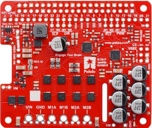
1 Pololu Dual G2 High-Power Motor Driver for Raspberry Pi 24v14 /POLOLU v18 /POLOLU v22 /POLOLU 3754 This add-on board makes it easy to control two highpower DC motors with a Raspberry Pi. Its twin discrete MOSFET H-bridges support a wide operating voltage range and are efficient enough to deliver a continuous current without a heat sink. The drivers offer basic current limiting functionality, and they accept ultrasonic PWM frequencies for quieter operation. The default pin mappings make it easy to get started, but they can be customized for more specialized applications.
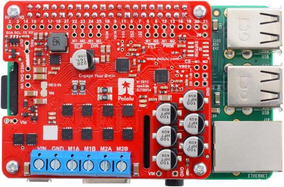
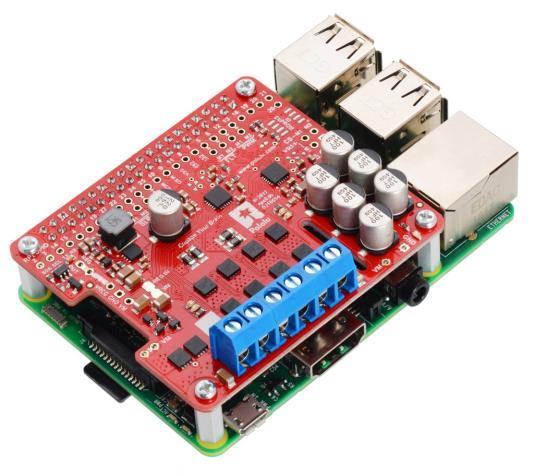
2 These G2 dual high-power motor drivers are add-on boards for the Raspberry Pi, featuring pairs of discrete MOSFET H-bridges designed to drive two large brushed DC motors. They are designed to mount on and plug into compatible Raspberry Pi boards (Model B+ or newer), including the Pi 3 Model B and Model A+. Three versions are available so you can pick the one with the appropriate operating voltage range and output current capabilities for your project: DUAL G2 HIGH- POWER MOTOR DRIVER 18V22 FOR RASPBERRY PI DUAL G2 HIGH- POWER MOTOR DRIVER 18V18 FOR RASPBERRY PI DUAL G2 HIGH- POWER MOTOR DRIVER 24V14 FOR RASPBERRY PI ABSOLUTE MAX INPUT VOLTAGE: 30 V 36 V* MAX NOMINAL BATTERY VOLTAGE: 18 V 28 V MAX CONTINUOUS CURRENT PER CHANNEL: 22 A 18 A 14 A DEFAULT ACTIVE CURRENT- LIMITING THRESHOLD: 60 A 50 A 40 A * 40 V if regulator is disconnected The minimum operating voltage for all four versions is 6.5 V, while the maximum operating voltages are given in the above table. The board also includes an integrated 5 V, 2.5 A switching step-down regulator that can be used to power the Raspberry Pi it is plugged into, enabling operation from a single power supply.
3 The driver s default configuration uses six GPIO pins to control the motor drivers, making use of the Raspberry Pi s hardware PWM outputs, and it uses two additional pins to read status outputs from the drivers. However, the pin mappings can be customized if the defaults are not convenient, and pins for current sensing and limiting are accessible on the board for more advanced applications. Note that this motor driver add-on is designed specifically for newer versions of the Raspberry Pi with 40-pin GPIO headers, including the Model B+, Model A+, Raspberry Pi 2 Model B, and Raspberry Pi 3 Model B. The board matches the Raspberry Pi HAT (Hardware Attached on Top) mechanical specification, although it does not conform to the full HAT specifications due to the lack of an ID EEPROM. (A footprint for adding your own EEPROM is available for applications where one would be useful; pull-ups on SDA, SCL, and WP are provided.) It is not practical to use this expansion board with the original Raspberry Pi Model A or Model B due to differences in their pinout and form factor. Features common to all versions PWM operation up to 100 khz Motor indicator LEDs show what the outputs are doing even when no motor is connected Integrated 5 V, 2.5 A switching step-down voltage regulator powers the Raspberry Pi base for single-supply operation Python library makes it easy to get started using this board as a motor driver expansion board GPIO pin mappings can be customized if the default mappings are not convenient Current sensing and limiting pins are exposed for advanced use Reverse-voltage protection Undervoltage shutdown Short circuit protection The following through-hole connectors and mounting hardware are included with the board, which ships with its surface-mount components populated: one 2 20-pin 0.1 female header three 2-pin 5 mm terminal blocks four M2.5 standoffs (11 mm length), screws, and nuts

4 The 2 20-pin 0.1 female header should be mounted to the bottom of the board (the side opposite the surface-mount components). Once soldered, this header is used to connect the board to the Raspberry Pi s 40-pin GPIO header. Alternatively, if you want to continue to have access to the Raspberry Pi s 40 GPIO pins while the motor driver board is plugged in, you can install a stackable 2 20-pin female header (not included) instead. You can solder the terminal blocks to the six large through-holes to make your motor and motor power connections, or you can solder a 0.1 male header strip (not included) into the smaller through-holes that border these larger holes. Note, however, that the terminal blocks are only rated for 16 A, and each header pin pair is only rated for a combined 6 A, so for higher-power applications, thick wires should be soldered directly to the board. The motor driver includes six 100 μf or 150 μf electrolytic power capacitors, and there is room to add additional capacitors (e.g. to compensate for long power wires or increase stability of the power supply). Additional power capacitors are usually not necessary, and no additional capacitors are included with this motor driver. Using the motor driver board Power An appropriate motor power supply should be connected to the motor driver s large VIN and GND pads. The board includes a reverse-voltage protection circuit that helps prevent damage in case the motor power supply is connected backward. The reverseprotected input voltage can be accessed for use in other circuits through the two pins labeled VM on the left side of the board.
5 By default, the motor power supply also feeds a 5 V, 2.5 A switching step-down regulator that provides power to the connected Raspberry Pi. An ideal diode circuit makes it safe to have a different power supply connected to the Raspberry Pi through its USB Micro-B receptacle while the motor driver is connected and powered. If you want to power the Raspberry Pi separately, the regulator can be disconnected by cutting two exposed traces on the board: one between the surface-mount pads labeled VM and REG IN, and another between the two pins by the REG OUT label, as shown to the right. On the 24v14 and 24v18 versions, disconnecting the regulator increases the absolute maximum operating voltage of the board to 40 V. Default pin mappings This table shows how the Raspberry Pi s GPIO pins are used to interface with the motor drivers: RPI GPIO PIN MOTOR DRIVER PIN DESCRIPTION 5 Motor 1 FLT Fault indicator: When the driver channel is functioning normally, this pin should be pulled high by the Raspberry 6 Motor 2 FLT Pi. In the event of a driver fault, FLT is driven low. See below for details Motor 1 PWM Motor 2 PWM Motor speed input: A PWM (pulse-width modulation) signal on this pin corresponds to a PWM output on the corresponding channel s motor outputs. When this pin is low, the motor brakes low. When it is high, the motor is on. The maximum allowed PWM frequency is 100 khz Motor 1 SLP Motor 2 SLP Inverted sleep input: This pin is pulled low by default, putting the motor driver channel into a low-current sleep mode and disabling the motor outputs (setting them to high impedance). SLPmust be driven high to enable the motor channel. 24 Motor 1 DIR Motor direction input: When DIR is low, motor current flows from output A to output B; when DIR is high, current 25 Motor 2 DIR flows from B to A.
6 Motor control options With the PWM pin held low, both motor outputs will be held low (a brake operation). With PWM high, the motor outputs will be driven according to the DIR input. This allows two modes of operation: sign-magnitude, in which the PWM duty cycle controls the speed of the motor and DIR controls the direction, and locked-antiphase, in which a pulse-width-modulated signal is applied to the DIR pin with PWM held high. In locked-antiphase operation, a low duty cycle drives the motor in one direction, and a high duty cycle drives the motor in the other direction; a 50% duty cycle turns the motor off. A successful locked-antiphase implementation depends on the motor inductance and switching frequency smoothing out the current (e.g. making the current zero in the 50% duty cycle case), so a high PWM frequency might be required. INPUTS OUTPUTS SLP DIR PWM MXA MXB OPERATION 1 0 PWM PWM (H/L) L forward/brake at speed PWM % 1 1 PWM L PWM (H/L) reverse/brake at speed PWM % 1 X 0 L L brake low (outputs shorted to ground) 0 X X Z Z coast (outputs off) PWM frequency The motor driver supports PWM frequencies as high as 100 khz, but note that switching losses in the driver will be proportional to the PWM frequency. Typically, around 20 khz is a good choice for sign-magnitude operation since it is high enough to be ultrasonic, which results in quieter operation.
, so low duty cycles become unavailable at high frequencies.")
7 A pulse on the PWM pin must be high for a minimum duration of approximately 0.5 µs before the outputs turn on for the corresponding duration (any shorter input pulse does not produce a change on the outputs), so low duty cycles become unavailable at high frequencies. For example, at 100 khz, the pulse period is 10 µs, and the minimum nonzero duty cycle achievable is 0.5/10, or 5%. Fault conditions The motor driver can detect several fault states that it reports by driving the FLT pin low; this is an open-drain output that should be pulled up to your system s logic voltage. The detectable faults include short circuits on the outputs, under-voltage, and overtemperature. All of the faults disable the motor outputs but are not latched, meaning the driver will attempt to resume operation when the fault condition is removed (or after a delay of a few milliseconds in the case of the short circuit fault). The over-temperature fault provides a weak indication of the board being too hot, but it does not directly indicate the temperature of the MOSFETs, which are usually the first components to overheat, so you should not count on this fault to prevent damage from overtemperature conditions. Remapping pins All of the Raspberry Pi s GPIO pins are broken out along a row of numbered throughholes just below the 40-pin GPIO connector. Each GPIO pin used by the board is connected from this row to the corresponding motor driver pin by a trace on the top side of the board spanning the pair of holes. If you want to remap one of these motor driver pins, you can cut its trace with a knife and then run a wire from the lower hole to a new GPIO pin.
; if you remap the motor driver pins without paying attention to this, you might encounter issues with pins being pulled the wrong way.")
8 Note that the default pin mappings were chosen so that the Raspberry Pi s default GPIO pull-ups and pull-downs match the direction the motor driver pins are or should be pulled (up for SF, down for others); if you remap the motor driver pins without paying attention to this, you might encounter issues with pins being pulled the wrong way. See the Raspberry Pi documentation for more about the default GPIO states. Current sensing and limiting The motor driver exposes current sensing and limiting pins that are not connected to the Raspberry Pi, but they are accessible through their own through-holes in case you want to use them in a more advanced application. The driver has the ability to limit the motor current through current chopping: once the motor drive current reaches a set threshold, the driver goes into brake mode (slow decay) for about 25 μs before applying power to drive the motor again. This makes it more practical to use the driver with a motor that might only draw a few amps while running but can draw many times that amount (tens of amps) when starting. For each motor channel, you can lower the limit by connecting an additional resistor between the VREF pin and the adjacent GND pin; the graph shows how the current limit relates to the VREF resistor value. Note that the current limiting threshold is not highly precise, and is less accurate at especially low settings (indicated by the dashed portion of the curve). The driver s current sense pins, labeled CS, output voltages proportional to the motor currents while the H-bridges are driving. The output voltage for this version is about 20 mv/a plus a small offset, which is typically about 50 mv.
9 Each CS output is only active while the corresponding H-bridge is in drive mode; it is inactive (low) when the channel is in brake mode (slow decay), which happens when the PWM input is low or when current limiting is active. Current will continue to circulate through the motor when the driver begins braking, but the voltage on the CS pin will not accurately reflect the motor current in brake mode. The CS voltage is used internally by the motor driver, so to avoid interfering with the driver s operation, you should not add a capacitor to this pin or connect a load that draws more than a few ma from it. Real-world power dissipation considerations The MOSFETs can handle large current spikes for short durations (e.g. 100 A for a few milliseconds), and the driver s current chopping will keep the average current under the set limit. The peak ratings are for quick transients (e.g. when a motor is first turned on), and the continuous rating is dependent on various conditions, such as the ambient temperature. PWMing the motor will introduce additional heating proportional to the frequency. The actual current you can deliver will depend on how well you can keep the motor driver cool. The driver s printed circuit board is designed to draw heat out of the MOSFETs, but performance can be improved by adding a heat sink or air flow. For high-current installations, the motor and power supply wires should also be soldered directly instead of going through the supplied terminal blocks, which are rated for up to 16 A. Warning: This motor driver has no over-temperature shut-off. An overtemperature or over-current condition can cause permanent damage to the motor driver. You might consider using either the driver s integrated current sense output (with an external ADC) or an external current sensor to monitor your current draw. This product can get hot enough to burn under normal operating conditions. Take care when handling this product and other components connected to it. Python library for the Pololu Dual G2 High Power Motor Drivers for Raspberry Pi -

10
POLOLU DUAL MC33926 MOTOR DRIVER FOR RASPBERRY PI (ASSEMBLED) USER S GUIDE
 USER S GUIDE") POLOLU DUAL MC33926 MOTOR DRIVER FOR RASPBERRY PI (ASSEMBLED) DETAILS FOR ITEM #2756 USER S GUIDE This version of the motor driver is fully assembled, with a 2 20-pin 0.1 female header (for connecting
POLOLU DUAL MC33926 MOTOR DRIVER FOR RASPBERRY PI (ASSEMBLED) DETAILS FOR ITEM #2756 USER S GUIDE This version of the motor driver is fully assembled, with a 2 20-pin 0.1 female header (for connecting
Pololu DRV8835 Dual Motor Driver Kit for Raspberry Pi B+
 Pololu DRV8835 Dual Motor Driver Kit for Raspberry Pi B+ Pololu DRV8835 dual motor driver board for Raspberry Pi B+, top view with dimensions. Overview This motor driver kit and its corresponding Python
DRV8801 Single Brushed DC Motor Driver Carrier
 Overview DRV8801 Single Brushed DC Motor Driver Carrier DRV8801 single brushed DC motor driver carrier with dimensions. Texas Instruments DRV8801 is a tiny H-bridge motor driver IC that can be used for
USER S GUIDE POLOLU DRV8838 SINGLE BRUSHED DC MOTOR DRIVER CARRIER USING THE MOTOR DRIVER
 POLOLU DRV8838 SINGLE BRUSHED DC MOTOR DRIVER CARRIER USER S GUIDE USING THE MOTOR DRIVER Minimal wiring diagram for connecting a microcontroller to a DRV8838 Single Brushed DC Motor Driver Carrier. Motor
POLOLU MAX14870 SINGLE BRUSHED DC MOTOR DRIVER CARRIER USER S GUIDE
 POLOLU MAX14870 SINGLE BRUSHED DC MOTOR DRIVER CARRIER USER S GUIDE USING THE MOTOR DRIVER Minimal wiring diagram for connecting a microcontroller to a MAX14870 Single Brushed DC Motor Driver Carrier.
TB6612FNG Dual Motor Driver Carrier
 TB6612FNG Dual Motor Driver Carrier Overview The TB6612FNG (308k pdf) is a great dual motor driver that is perfect for interfacing two small DC motors such as our micro metal gearmotors to a microcontroller,
Simple-H User Manual
 Simple-H User Manual Thank you for your purchase of the Robot Power Simple-H. This manual explains the features and functions of the Simple-H along with some tips for successful application. Before using
DeviceCraft Revision #1 11/29/2010
 DeviceCraft Revision #1 11/29/2010 DC Wiper Motor H-Bridge Servo / Speed Controller P/N 1020 Features: Dip Switch selectable mode of operation Both PID servo or speed controller Forward/Reverse operation
High Capacity H-Bridge
 High Capacity H-Bridge Functional Specification Revision 1.0 4822 Sterling Drive Boulder, CO 80301 Page 1 Revision History 3 Features 3 General Description 3 Functional Block Diagram 4 Recommended and
A4950. Full-Bridge DMOS PWM Motor Driver. Description
 Features and Benefits Low R DS(on) outputs Overcurrent protection (OCP) Motor short protection Motor lead short to ground protection Motor lead short to battery protection Low Power Standby mode Adjustable
USER S GUIDE POLOLU A4988 STEPPER MOTOR DRIVER CARRIER USING THE DRIVER POWER CONNECTIONS
 POLOLU A4988 STEPPER MOTOR DRIVER CARRIER USER S GUIDE USING THE DRIVER Minimal wiring diagram for connecting a microcontroller to an A4988 stepper motor driver carrier (full-step mode). POWER CONNECTIONS
7I30 MANUAL Quad 100W HBridge
 7I30 MANUAL Quad 100W HBridge V1.3 This page intentionally almost blank Table of Contents GENERAL.......................................................... 1 DESCRIPTION.................................................
A4954 Dual Full-Bridge DMOS PWM Motor Driver
 Dual Full-Bridge DMOS Features and Benefits Low R DS(on) outputs Overcurrent protection (OCP) Motor short protection Motor lead short to ground protection Motor lead short to battery protection Low Power
PHASE BRUSHLESS DC MOTOR CONTROLLER/DRIVER FEATURES
 Data Sheet 29318.20B 2936-120 Combining logic and power, the UDN2936W-120 provides commutation and drive for three-phase brushless dc motors. Each of the three outputs are rated at 45 V and ±2 A (±3 A
The NMIH-0050 H-Bridge
 The NMIH-0050 H-Bridge Features: 5 A continuous, 6 A peak current Supply voltages from 5.3V up to 40V Terminal block for power / motor Onboard LEDs for motor operation/direction Onboard LED for motor supply
RB-Pol-116 Pololu D24V6ALV Step-Down Voltage Regulator Overview
 RB-Pol-116 Pololu D24V6ALV Step-Down Voltage Regulator Overview These adjustable buck (step-down) voltage regulators from Pololu generate lower, user-adjustable output voltages from a wide input voltage
A3901. Dual Full Bridge Low Voltage Motor Driver
 A39 Features and Benefits ow R DS(on) outputs Full- and half-stepping capability Small package Forward, reverse, and brake modes for DC motors Sleep mode with zero current drain PWM control up to 25 khz
MP V, 3.2A, H-Bridge Motor Driver
 MP6522 35V, 3.2A, H-Bridge Motor Driver DESCRIPTION The MP6522 is an H-bridge motor driver that operates from a supply voltage of up to 35V and delivers a peak motor current of up to 3.2A. The MP6522 is
Designing with the Si9976DY N-Channel Half-Bridge Driver and LITTLE FOOT Dual MOSFETs
 Designing with the DY N-Channel Half-ridge Driver and s Wharton McDaniel The DY is a fully integrated half-bridge driver IC which was designed to work with the family of power products in 0- to 0-V systems.
A5957. Full-Bridge PWM Gate Driver PACKAGE:
 FEATURES AND BENEFITS PHASE/ENABLE/SLEEPn control logic Overcurrent indication Adjustable off-time and blank-time Adjustable current limit Adjustable gate drive Synchronous rectification Internal UVLO
DUAL STEPPER MOTOR DRIVER
 DUAL STEPPER MOTOR DRIVER GENERAL DESCRIPTION The is a switch-mode (chopper), constant-current driver with two channels: one for each winding of a two-phase stepper motor. is equipped with a Disable input
Figure 1. DMC 60 components.
 1300 Henley Court Pullman, WA 99163 509.334.6306 www.digilentinc.com DMC 60 Reference Manual Revised November 15, 2016 This manual applies to the DMC 60 rev. A Overview The DMC 60 is an electronic speed
A3950. DMOS Full-Bridge Motor Driver
 Features and Benefits Low R DS(on) outputs Overcurrent protection Motor lead short-to-supply protection Short-to-ground protection Sleep function Synchronous rectification Diagnostic output Internal undervoltage
MLX83100 Automotive DC Pre-Driver EVB83100 for Brushed DC Applications with MLX83100
 EVB83100 for Brushed DC Applications with MLX83100 Stefan Poels JULY 17, 2017 VAT BE 0435.604.729 Transportstraat 1 3980 Tessenderlo Phone: +32 13 67 07 95 Mobile: +32 491 15 74 18 Fax: +32 13 67 07 70
40 Amp Digital Bidirectional PWM Motor Controller with Regenerative Braking BIDIR-340-DR
 40 Amp Digital Bidirectional PWM Motor Controller with Regenerative Braking BIDIR-340-DR The BIDIR-340-DR is a fully solid-state motor controller that allows you to control the speed and direction of a
150mA, Low-Dropout Linear Regulator with Power-OK Output
 9-576; Rev ; /99 5mA, Low-Dropout Linear Regulator General Description The low-dropout (LDO) linear regulator operates from a +2.5V to +6.5V input voltage range and delivers up to 5mA. It uses a P-channel
AMT Quad DMOS Full-Bridge PWM Motor Driver FEATURES AND BENEFITS DESCRIPTION
 FEATURES AND BENEFITS 18 V output rating 4 full bridges Dual stepper motor driver High-current outputs 3.3 and 5 V compatible logic Synchronous rectification Internal undervoltage lockout (UVLO) Thermal
A3984. DMOS Microstepping Driver with Translator
 Features and Benefits Low RDS(ON) outputs Automatic current decay mode detection/selection and current decay modes Synchronous rectification for low power dissipation Internal UVLO and thermal shutdown
A3995. DMOS Dual Full Bridge PWM Motor Driver
 Features and Benefits 6 V output rating.4 A, DC motor driver Synchronous rectification Internal undervoltage lockout (UVLO) Thermal shutdown circuitry Crossover-current protection Very thin profile QFN
AMT Dual DMOS Full-Bridge Motor Driver PACKAGE: AMT49702 AMT49702
 FEATURES AND BENEFITS AEC-Q100 Grade 1 qualified Wide, 3.5 to 15 V input voltage operating range Dual DMOS full-bridges: drive two DC motors or one stepper motor Low R DS(ON) outputs Synchronous rectification
NJM3777 DUAL STEPPER MOTOR DRIVER NJM3777E3(SOP24)
") DUAL STEPPER MOTOR DRIER GENERAL DESCRIPTION The NJM3777 is a switch-mode (chopper), constant-current driver with two channels: one for each winding of a two-phase stepper motor. The NJM3777 is equipped
DUAL STEPPER MOTOR DRIER GENERAL DESCRIPTION The NJM3777 is a switch-mode (chopper), constant-current driver with two channels: one for each winding of a two-phase stepper motor. The NJM3777 is equipped
A3949. DMOS Full-Bridge Motor Driver. Features and Benefits Single supply operation Very small outline package Low R DS(ON)
") Features and Benefits Single supply operation Very small outline package Low R DS(ON) outputs Sleep function Internal UVLO Crossover current protection Thermal shutdown protection Packages: Description
Features and Benefits Single supply operation Very small outline package Low R DS(ON) outputs Sleep function Internal UVLO Crossover current protection Thermal shutdown protection Packages: Description
Transform. Isolate. Regulate
 4707 DEY ROAD LIVERPOOL, NY 13088 PHONE: (315) 701-6751 FAX: (315) 701-6752 M.S. KENNEDY CORPORATION MSK Web Site: http://www.mskennedy.com/ DC - DC Converters MS Kennedy Corp.; Revised 9/19/2013 Application
A3916. Dual DMOS Full-Bridge Motor Driver. PACKAGEs: A3916 A3916
 FEATURES AND BENEFITS Wide,.7 to 5 V input voltage operating range Dual DMOS full-bridges: drive two D motors or one stepper motor Low R DS(ON) outputs Synchronous rectification for reduced power dissipation
SGM2553/SGM2553D Precision Adjustable Current Limited Power Distribution Switches
 /D GENERAL DESCRIPTION The and D power distribution switches are intended for applications where precision current limiting is required or heavy capacitive loads and short circuits are encountered and
System Board 6219 MAXREFDES89#: MAX14871 Full-Bridge DC Motor Driver MBED Shield
 System Board 6219 MAXREFDES89#: MAX14871 Full-Bridge DC Motor Driver MBED Shield Introduction Brushed DC motors provide cost-effective, convenient motion in many applications ranging from electric toothbrushes
Application Note CDIAN003
 Application Note CDIAN003 CDI GaN Bias Board User s Guide Revision 4.0 February 20, 2015 Quick Start Guide Shown below are the essential connections, controls, and indicators for the GaN Bias Control Board.
DC Brushed Motor Controller Module EDP-AM-MC1
 Embedded Development Platform DC Brushed Motor Controller Module EDP-AM-MC1 Electrocomponents plc Vsn 1.1 Page 1 DC Brushed Motor Controller Module EDP-AM-MC1 The motor controller module is designed to
A Phase Sinusoidal Motor Controller. Description
 Features and Benefits Sinusoidal Drive Current Hall Element Inputs PWM Current Limiting Dead-time Protection FGO (Tach) Output Internal UVLO Thermal Shutdown Circuitry Packages: 32-Pin QFN (suffix ET)
Adafruit 16-Channel PWM/Servo HAT & Bonnet for Raspberry Pi
 Adafruit 16-Channel PWM/Servo HAT & Bonnet for Raspberry Pi Created by lady ada Last updated on 2018-03-21 09:56:10 PM UTC Guide Contents Guide Contents Overview Powering Servos Powering Servos / PWM OR
A3982. DMOS Stepper Motor Driver with Translator
 OUT2A SENSE2 VBB2 OUT2B ENABLE PGND PGND CP1 CP2 VCP VREG MS1 1 2 3 4 5 6 7 8 9 10 11 12 Charge Pump Reg Package LB Translator & Control Logic AB SO LUTE MAX I MUM RAT INGS Load Supply Voltage,V BB...35
Adafruit 16-channel PWM/Servo Shield
 Adafruit 16-channel PWM/Servo Shield Created by lady ada Last updated on 2018-08-22 03:36:11 PM UTC Guide Contents Guide Contents Overview Assembly Shield Connections Pins Used Connecting other I2C devices
PART MAX1658C/D MAX1659C/D TOP VIEW
 19-1263; Rev 0; 7/97 350mA, 16.5V Input, General Description The linear regulators maximize battery life by combining ultra-low supply currents and low dropout voltages. They feature Dual Mode operation,
OUTPUT UP TO 300mA C2 TOP VIEW FAULT- DETECT OUTPUT. Maxim Integrated Products 1
 19-1422; Rev 2; 1/1 Low-Dropout, 3mA General Description The MAX886 low-noise, low-dropout linear regulator operates from a 2.5 to 6.5 input and is guaranteed to deliver 3mA. Typical output noise for this
DESCRIPTION 50 V 50 V 50 V CP1 CP2 VCP VBB VBB. SLEEPn OUT1A OUT1B SENSE1 PHASE1 I01 A5989 I11 PHASE2 I02 I12 OUT2A OUT2B SENSE2
 FEATURES AND BENEFITS 4 V output rating 3.2 A DC motor driver 1.6 A bipolar stepper driver Synchronous rectification Internal undervoltage lockout (UVLO) Thermal shutdown circuitry Crossover-current protection
AMP-19520/40. Multi-axis Brushless/Brush Servo Amplifier. By Galil Motion Control, Inc. Rev. 1.0d
 Multi-axis Brushless/Brush Servo Amplifier AMP-9520/40 Rev..0d By Galil Motion Control, Inc. Galil Motion Control, Inc. 270 Technology Way Rocklin, California 95765 Phone: (96) 626-00 Fax: (96) 626-002
BLOCK DIAGRAM OF THE UC3625
 U-115 APPLICATION NOTE New Integrated Circuit Produces Robust, Noise Immune System For Brushless DC Motors Bob Neidorff, Unitrode Integrated Circuits Corp., Merrimack, NH Abstract A new integrated circuit
A3987. DMOS Microstepping Driver with Translator
 Features and Benefits Low R DS(on) outputs Short-to-ground protection Shorted load protection Automatic current decay mode detection/selection and slow current decay modes Synchronous rectification for
EUP /8.4A Switch Mode Li-Ion/Polymer Battery Charger
 Switch Mode Li-Ion/Polymer Battery Charger DESCRIPTION FEATURES The EUP8202 is a constant current, constant voltage Wide Input Supply Voltage Range: Li-Ion battery charger controller that uses a current
LD /07/ Channel LED Backlight Driver. General Description. Features. Applications. Typical Application REV: 05
 10/07/2011 4 Channel LED Backlight Driver REV: 05 General Description The LD7889 is a 4-channel linear current controller which combines with a boost switching controller. It s an ideal solution for driving
NJM3773 DUAL STEPPER MOTOR DRIVER
 NJ77 DUAL STEPPE OTO DIE GENEAL DESCIPTION The NJ77 is a switch-mode (chopper), constant-current driver with two channels: one for each winding of a two-phase stepper motor. The NJ77 is also equipped with
Ocean Controls KT-5198 Dual Bidirectional DC Motor Speed Controller
 Ocean Controls KT-5198 Dual Bidirectional DC Motor Speed Controller Microcontroller Based Controls 2 DC Motors 0-5V Analog, 1-2mS pulse or Serial Inputs for Motor Speed 10KHz, 1.25KHz or 156Hz selectable
Functional description of BSD-01 Module. Features
 Functional description of BSD-01 Module The BSD-01 module is a complete microstepping driver with built-in translator suitable for driving bipolar step motors up to 750mA and 30V. It operates in Full-,
Functional description of BSD-01v2 Module
 Functional description of BSD-01v2 Module The BSD-01v2 module is a complete microstepping driver with built-in translator suitable for driving bipolar step motors from 15 to 750mA and up to 30V. It comes
Designated client product
 Designated client product This product will be discontinued its production in the near term. And it is provided for customers currently in use only, with a time limit. It can not be available for your
LD7889A 3/29/ Channel LED Backlight Driver. General Description. Features. Applications. Typical Application REV: 00
 3/29/2012 4-Channel LED Backlight Driver REV: 00 General Description The LD7889A is a 4-channel linear current controller which combines with a boost switching controller. It s an ideal solution for driving
Qik 2s12v10 User's Guide
 1 Overview 2 Contacting Pololu 3 Connecting the Qik 3a Power and Motor Connections 3b Logic Connections 3c Included Hardware 3d Jumpers 3e Indicator LEDs and Phases of Operation 3f Board Dimensions and
LM5034 High Voltage Dual Interleaved Current Mode Controller with Active Clamp
 High Voltage Dual Interleaved Current Mode Controller with Active Clamp General Description The dual current mode PWM controller contains all the features needed to control either two independent forward/active
HB-25 Motor Controller (#29144)
") Web Site: www.parallax.com Forums: forums.parallax.com Sales: sales@parallax.com Technical: support@parallax.com Office: (916) 624-8333 Fax: (916) 624-8003 Sales: (888) 512-1024 Tech Support: (888) 997-8267
Web Site: www.parallax.com Forums: forums.parallax.com Sales: sales@parallax.com Technical: support@parallax.com Office: (916) 624-8333 Fax: (916) 624-8003 Sales: (888) 512-1024 Tech Support: (888) 997-8267
Adafruit 16-Channel PWM/Servo HAT for Raspberry Pi
 Adafruit 16-Channel PWM/Servo HAT for Raspberry Pi Created by lady ada Last updated on 2017-05-19 08:55:07 PM UTC Guide Contents Guide Contents Overview Powering Servos Powering Servos / PWM OR Current
NJM37717 STEPPER MOTOR DRIVER
 STEPPER MOTOR DRIVER GENERAL DESCRIPTION PACKAGE OUTLINE NJM37717 is a stepper motor diver, which consists of a LS-TTL compatible logic input stage, a current sensor, a monostable multivibrator and a high
0.7 A 6.8 V Dual H-Bridge Motor Driver
 Freescale Semiconductor Technical Data Document Number: MPC Rev. 3.0, 12/2013 0.7 A 6.8 V Dual H-Bridge Motor Driver The is a monolithic dual H-Bridge power IC ideal for portable electronic applications
Qik 2s12v10 User's Guide
 Qik 2s12v10 User's Guide 1. Overview.................................................... 2 2. Contacting Pololu................................................ 4 3. Connecting the Qik...............................................
A4970. Dual Full-Bridge PWM Motor Driver
 Dual Full-Bridge PWM Motor Driver Features and Benefits 750 ma continuous output current 45 V output sustaining voltage Internal clamp diodes Internal PWM current control Low output saturation voltage
Tarocco Closed Loop Motor Controller
 Contents Safety Information... 3 Overview... 4 Features... 4 SoC for Closed Loop Control... 4 Gate Driver... 5 MOSFETs in H Bridge Configuration... 5 Device Characteristics... 6 Installation... 7 Motor
LMD A, 55V H-Bridge
 3A, 55V H-Bridge General Description The LMD18201 is a 3A H-Bridge designed for motion control applications. The device is built using a multi-technology process which combines bipolar and CMOS control
MIC29150/29300/29500/29750 Series
 MIC29/293/29/297 www.tvsat.com.pl Micrel MIC29/293/29/297 Series High-Current Low-Dropout Regulators General Description The MIC29/293/29/297 are high current, high accuracy, low-dropout voltage regulators.
LSI/CSI LS7560N LS7561N BRUSHLESS DC MOTOR CONTROLLER
 LSI/CSI LS7560N LS7561N LSI Computer Systems, Inc. 15 Walt Whitman Road, Melville, NY 747 (631) 71-0400 FAX (631) 71-0405 UL A3800 BRUSHLESS DC MOTOR CONTROLLER April 01 FEATURES Open loop motor control
Features. +12V to +36V MIC nf. High-Side Driver with Overcurrent Trip and Retry
 MIC0 MIC0 High-Speed High-Side MOSFET Driver General Description The MIC0 high-side MOSFET driver is designed to operate at frequencies up to 00kHz (khz PWM for % to 00% duty cycle) and is an ideal choice
Analog Servo Drive 20A20
 Description Power Range NOTE: This product has been replaced by the AxCent family of servo drives. Please visit our website at www.a-m-c.com or contact us for replacement model information and retrofit
SRPE-50E1A0 Non-Isolated DC-DC Converter
 SRPE-50E1A0 Non-Isolated DC-DC Converter The Bel SRPE-50E1A0 is part of the non-isolated dc to dc converter Power Module series. The modules use a Vertical SMT package. These converters are available in
Analog Servo Drive 30A20AC
 Description Power Range NOTE: This product has been replaced by the AxCent family of servo drives. Please visit our website at www.a-m-c.com or contact us for replacement model information and retrofit
75 VOLT 8 AMP MOSFET H-BRIDGE PWM MOTOR DRIVER/AMPLIFIER
 M.S.KENNEDY CORP. 75 OLT 8 AMP MOSFET HBRIDGE PWM MOTOR DRIER/AMPLIFIER 4707 Dey Road Liverpool, N.Y. 088 (5) 70675 FEATURES: Low Cost Complete HBridge 8 Amp Capability, 75 olt Maximum Rating Selfcontained
PowerAmp Design. PowerAmp Design PAD20 COMPACT HIGH VOLTAGE OP AMP
 PowerAmp Design Rev C KEY FEATURES LOW COST HIGH VOLTAGE 150 VOLTS HIGH OUTPUT CURRENT 5A 40 WATT DISSIPATION CAPABILITY 80 WATT OUTPUT CAPABILITY INTEGRATED HEAT SINK AND FAN SMALL SIZE 40mm SQUARE RoHS
2A, 23V, 380KHz Step-Down Converter
 2A, 23V, 380KHz Step-Down Converter General Description The is a buck regulator with a built-in internal power MOSFET. It achieves 2A continuous output current over a wide input supply range with excellent
Pin # Pin Name Pin Type Description. 4 GND Signal ground Signal ground pin. Connect ADC and DAC grounds to here.
 FEATURES High Efficiency: 90% Maximum Output Current: 2A No Heat Sink Required Current and Power Programming, Modulation & Monitoring Capabilities. Current Output Noise: 0.05% High Stability: 100ppm/ C
Analog Technologies. Dual Mode Laser Driver LDA1-CP1-D
 FEATURES High Efficiency: 90% Maximum Output Current: 2A No Heat Sink Required Current and Power Programming, Modulation & Monitoring Capabilities. Current Output Noise: 0.05% High Stability: 100ppm/ C
UNISONIC TECHNOLOGIES CO., LTD US2076 Preliminary CMOS IC
 UNISONIC TECHNOLOGIES CO., LTD US2076 Preliminary CMOS IC DUAL HIGH-SIDE POWER SWITCH DESCRIPTION The UTC US2076 is a dual integrated high-side power switch particularly designed for self-powered and bus-powered
SA305 FEATURES APPLICATIONS DESCRIPTION EXTERNAL CONNECTIONS BLOCK DIAGRAM
 M I C R O T E C H N O L O G Y SA305 FEATURES LOW COST 3 PHASE INTELLIGENT SWITCHING AMPLIFIER 3 FULLY PROTECTED HALF BRIDGES UP TO 60V SUPPLY OUTPUT CURRENT - 5 AMPS (CONT) PER HALF BRIDGE NO SHOOT THROUGH
SGM2551A/SGM2551C Precision Adjustable Current Limited Power Distribution Switches
 / GENERAL DESCRIPTION The SGM2551A and power distribution switches are intended for applications where precision current limiting is required or heavy capacitive loads and short circuits are encountered
ML4818 Phase Modulation/Soft Switching Controller
 Phase Modulation/Soft Switching Controller www.fairchildsemi.com Features Full bridge phase modulation zero voltage switching circuit with programmable ZV transition times Constant frequency operation
LD7523 6/16/2009. Smart Green-Mode PWM Controller with Multiple Protections. General Description. Features. Applications. Typical Application REV: 00
 6/16/2009 Smart Green-Mode PWM Controller with Multiple Protections REV: 00 General Description The LD7523 is a low startup current, current mode PWM controller with green-mode power-saving operation.
Discontinued Product
 Data Sheet 29319.4 NC REF/ BRAKE RC PHASE ENABLE 1 2 3 4 5 6 V CC ASB 7 10 8 9 ABSOLUTE MAXIMUM RATINGS Load Supply Voltage,... 50 V Output Current, I OUT (t w 20 µs)... ±3.5 A (Continuous)... ±2.0 A Logic
Jaguar Motor Controller (Stellaris Brushed DC Motor Control Module with CAN)
") Jaguar Motor Controller (Stellaris Brushed DC Motor Control Module with CAN) 217-3367 Ordering Information Product Number Description 217-3367 Stellaris Brushed DC Motor Control Module with CAN (217-3367)
Jaguar Motor Controller (Stellaris Brushed DC Motor Control Module with CAN) 217-3367 Ordering Information Product Number Description 217-3367 Stellaris Brushed DC Motor Control Module with CAN (217-3367)
A5976. Microstepping DMOS Driver with Translator
 FEATURES AND BENEFITS ±2.8 A, 40 V output rating Low R DS(on) outputs, 0.22 Ω source, 0.15 Ω sink typical Automatic current decay mode detection/selection 3 to 5.5 V logic supply voltage range Mixed, fast,
Power Pulse Modulator A High Performance Versatile Square Pulse Generator
 Power Pulse Modulator A High Performance Versatile Square Pulse Generator Model: PWM-OCXi v2.2 Type: High Voltage, 9A, 340V, 1.5MHz, Active Protection Features and Specifications * Max current varies with
PowerAmp Design. PowerAmp Design PAD117A RAIL TO RAIL OPERATIONAL AMPLIFIER
 PowerAmp Design RAIL TO RAIL OPERATIONAL AMPLIFIER Rev J KEY FEATURES LOW COST RAIL TO RAIL INPUT & OUTPUT SINGLE SUPPLY OPERATION HIGH VOLTAGE 100 VOLTS HIGH OUTPUT CURRENT 15A 250 WATT OUTPUT CAPABILITY
DESCRIPTION. Functional Block Diagram A4915 VBB. Charge Pump Regulator VREG. Bootstrap Monitor CA CB CC GHA GHB GHC SA SB SC C BOOTA.
 FEATURES AND BENEFITS 5 to 50 V supply voltage Latched TSD with fault output Drives six N-channel high current MOSFETs Internally controlled synchronous rectification Speed voltage input enables internal
A3909. Dual Full Bridge Motor Driver. Description. Features and Benefits. Packages: Functional Block Diagram
 Features and Benefits Low R DS(on) outputs Drives two DC motors or single stepper motor Low power standby (Sleep) mode with zero current drain Thermal shutdown protection Parallel operation option for.8
LM5032 High Voltage Dual Interleaved Current Mode Controller
 High Voltage Dual Interleaved Current Mode Controller General Description The LM5032 dual current mode PWM controller contains all the features needed to control either two independent forward dc/dc converters
APPLICATION NOTE. ATA6629/ATA6631 Development Board V2.2 ATA6629/ATA6631. Introduction
 APPLICATION NOTE ATA6629/ATA6631 Development Board V2.2 ATA6629/ATA6631 Introduction The development board for the Atmel ATA6629/ATA6631 (ATA6629-EK, ATA6631-EK) is designed to give users a quick start
High-Voltage, 3-Channel Linear High-Brightness LED Driver with Open LED Detection
 EVALUATION KIT AVAILABLE General Description The three-channel LED driver operates from a 5.5V to 40V input voltage range and delivers up to 100mA per channel to one or more strings of highbrightness (HB
LED Driver 4 click. PID: MIKROE 3037 Weight: 25 g
 LED Driver 4 click PID: MIKROE 3037 Weight: 25 g LED Driver 4 click is a form of a high-efficiency boost converter that is ideally suited for driving an array of white LEDs. The driver has the ability
Universal Input Switchmode Controller
 Universal Input Switchmode Controller Si9120 FEATURES 10- to 0- Input Range Current-Mode Control 12-mA Output Drive Internal Start-Up Circuit Internal Oscillator (1 MHz) and DESCRIPTION The Si9120 is a
IX2127NTR. High-Voltage Power MOSFET & IGBT Driver INTEGRATED CIRCUITS DIVISION. Description. Driver Characteristics. Features.
 High-Voltage Power MOSFET & IGBT Driver Driver Characteristics Parameter Rating Units V OFFSET 6 V I O +/- (Source/Sink) 25/5 ma V th 25 mv t ON / t OFF (Typical) 1 ns Features Floating Channel Designed
BL8573 FEATURES DESCRIPTION APPLICATIONS TYPICAL APPLICATION. 500mA/1.5A Standalone Linear Li-Ion Battery Charge
 DESCRIPTION The is a single cell, fully integrated constant current (CC)/constant voltage (CV) Li-ion battery charger. Its compact package with minimum external components requirement makes the ideal for
MDM5253 DC Motor Driver Module with Position and Current Feedback User Manual
 MDM5253 DC Motor Driver Module with Position and Current Feedback User Manual Version: 1.0.3 Apr. 2013 Table of Contents I. Introduction 2 II. Operations 2 II.1. Theory of Operation 2 II.2. Running as
Peak Current. Continuous Current. See Part Numbering Information on last page of datasheet for additional ordering options.
 Description Power Range The PWM servo drive is designed to drive brushless DC motors at a high switching frequency. A single red/green LED indicates operating status. The drive is fully protected against
Features. General Description. Component List
 MAX68 Evaluation Kit Evaluates: MAX68 General Description The MAX68 evaluation kit (EV kit) demonstrates the MAX68 high-brightness LED (HB LED) driver, integrating a step-up DC-DC preregulator followed
Features MIC2194BM VIN EN/ UVLO CS OUTP VDD FB. 2k COMP GND. Adjustable Output Buck Converter MIC2194BM UVLO
 MIC2194 400kHz SO-8 Buck Control IC General Description s MIC2194 is a high efficiency PWM buck control IC housed in the SO-8 package. Its 2.9V to 14V input voltage range allows it to efficiently step