General Technical Information 19. Data Sheets 41. Mounting Instructions 161 Quality 167 Environmental Protection, Climatic Conditions 173, 175
|
|
|
- Georgina Stanley
- 5 years ago
- Views:
Transcription
1 Page Contents 5 Selector Guide 9 Index of Types 17 General Technical Information 19 Data Sheets 41 Mounting Instructions 161 Quality 167 Environmental Protection, Climatic Conditions 173, 175 Taping and Packing 177 Symbols and Terms 183 Subject Index 185

2 S+M COMPONENTS Siemens Matsushita Components EMI suppression capacitors Play it safe Whether video recorder, television, refrigerator or toaster our EMI suppression capacitors do a grand job in every possible kind of entertainment and consumer electronics appliance. They ve also proven their worth in switch-mode power supplies for PCs. No wonder, because the advantages of film technology are there to be seen: low cost, no risk of failure through damp, and optimum selfhealing capability. The result less destruction of equipment and ensuing fires. Plus the line is safeguarded against surges. In this way our capacitors satisfy the user s need for safety, and the new EMC standards too of course. SCS dependable, fast and competent
3 PTC Thermistors


4 SCS on the Internet Creating new links As of now you can tie up with Passive Components and Electron Tubes Group plus Siemens Matsushita Components on the Internet. On our home page under you ll find the latest short form catalogs, data books, technical articles and more subjects too. You can view the documents on-line, or download them to your PC. The Installation menu item tells you how to do it. Thanks to the integrated search function, you only have to enter key terms to go straight to the right document. And of course, you can get in touch with us direct by E mail at any time. World Wide Web Service SCS dependable, fast and competent
5 Contents Selector guide 9 Index of types 17 General technical information 19 1 Definition 19 2 Structure and function 19 3 Manufacture 19 4 Characteristics Unloaded PTC thermistors Temperature dependence of resistance Rated resistance R N Minimum resistance R min Reference resistance R Ref at reference temperature T Ref Resistance R PTC at temperature T PTC Temperature coefficientα Nominal threshold temperature T NAT Electrically loaded PTC thermistors Surface temperature T surf Current/voltage characteristic Trip current I K Rated current I N and switching current I S Residual current I r Electrical maximum ratings I max, I Smax Maximum operating voltage V max, rated voltage V N, maximum measuring voltage V Meas,max and breakdown voltage V D Switching time t S Insulation test voltage V is Pulse strength V P Thermal characteristics Thermal cooling time constant τ c Thermal threshold time t a Response time t R Settling time t E 26 5 Notes on operating mode Voltage dependence of resistance Frequency dependence of resistance Influence of heat dissipation on PTC temperature Influence of ambient temperature on the I/V characteristic 28 6 Application notes PTC thermistors for overload protection Operating states of a PTC thermistor for overload protection Considerations on trip current 30 Contents Siemens Matsushita Components 5
6 Contents Switching time versus switching current Selection criteria Circuit configuration PTC thermistors for time delay PTC thermistors for motor starting PTC thermistors for picture tube degaussing PTC thermistors as level sensors PTC thermistors for measurement and control, temperature sensors PTC thermistors as heating elements 40 Data sheets 41 Overload protection 41 Disks 41 Rods 76 Telecom disks 78 SMDs 80 Degaussing 88 Switching 91 Motor starting 100 Motor and machine protection 102 Level sensors 126 Measurement and control 132 Disks 132 Probe assemblies 142 SMDs 148 Heating elements and thermostats 150 Mounting instructions Soldering Leaded PTC thermistors Leadless PTC thermistors SMD PTC thermistors Wettability test Soldering heat resistance test Recommended soldering temperature profiles Notes Conductive adhesion Clamp contacting Siemens Matsushita Components
7 Contents 4 Robustness of terminations Sealing and potting Cleaning Storage 165 Quality Manufacturing process and quality assurance General Sequence of quality assurance measures Incoming inspection Process assurance Product assurance Final inspection Delivery quality Sampling inspection Classification of defects AQL values Incoming inspection by the customer Reliability Identification and retraceability Supplementary information 172 Environmental protection measures 173 Climatic conditions Reliability data Operating temperature range 175 Taping and packing Taping of SMD thermistors Taping of radial-lead PTC thermistors Packing codes 181 Symbols and terms 183 Subject index 185 Siemens Matsushita Components 7

8 S+M COMPONENTS Siemens Matsushita Components European technology center for ceramic components There when you need us This is an organization that s proven its worth. Because it stands for more customer proximity and thus better service. Here you get information straight from the source, implementation of the latest technologies and products that match the market. Concentration of resources means that design engineers and production engineers are working side by side. And SCS warehousing directly at the plant ensures fastest possible delivery. SCS dependable, fast and competent
 54 55 1150 120 2370 160 0,9 55 47 B599*0 (C 9*0) 80 30 530 60 1100 80 0,9 55 50 B599*0 (C 9*0) 80 50 1000 100 2000 120 0,9 55 53 B598*0 (C 8*0) 160 35 800 70 1600 160")
9 Selector Guide PTC thermistors for overload protection Type B599*5 (C 9*5) B599*5 (C 9*5) V max V I N ma I S ma T Ref R N Page 160 0, , Selector Guide B599*0 (C 9*0) , B599*0 (C 9*0) , B599*0 (C 9*0) , B598*0 (C 8*0) , B598*0 (C 8*0) , B598*1 (C 8*1) , B598** (C 8**) , B597** (B 7**) Siemens Matsushita Components 9
10 Selector Guide PTC thermistors for overload protection Type B5940* (B 40*) V max V I N ma 2,5 4 I S ma 6,5 12 T Ref R N Page Telecom PTC thermistors B5902* (S 102*) B59707 (A 1707) B59607 (A 1607) B59*01 (P 1*01) ; 130 3, B59*15 (P 1*15) ; Siemens Matsushita Components
 B59100 (T100) 265 10 4 28 (typ.) 265 16 4 18 (typ.) 265 20 15 22 (typ.")
11 Selector Guide PTC thermistors for picture tube degaussing Type V max V I in I r R N A pp ma pp R coil Page B , (C 1250) 88 B59450 (C 1450) B59250 (T250) B59170 (T170) B59100 (T100) (typ.) (typ.) (typ.) Switching PTC thermistors Type B5911* (C 111*) V max V I N ma I S ma T Ref R N 80; ; 150 Page 91 B59xx0 (J 150) (J 200) (J 320) B59339 (J 2**) B593** (J 29) Siemens Matsushita Components 11
 V max V 175 400 I max ma 4 8 T Ref R N Page 120; 135 4,7")
 30 60 180 250 106 B59155")
 30 60 180 300 122 12 Siemens Matsushita")
12 Selector Guide PTC thermistors for motor starting Type B5919*; B5921* (A 19*, A 21*, J 19*, J 21*) V max V I max ma 4 8 T Ref R N Page 120; 135 4, PTC thermistors for motor and machine protection Type B59100 (M 1100) V max V T NAT R N Page 102 B59135 (M 135) B59155 (M 155) B59300 (M 1300) B59335 (M 335) B59355 (M 355) Siemens Matsushita Components
13 Selector Guide PTC thermistors as level sensors Type Q63100 (E 11) V max V I r, oil ma I r, air ma t S s R N , Page 126 B59020 (E 1020) 24 41,7 26, B59010 (D 1010) , PTC thermistors for measurement and control Type B59011 (C 1011) V max V I max ma T Ref R N Page 110 > 100 k 132 B59012 (C 1012) B59013 (C 1013) Siemens Matsushita Components 13
14 Selector Guide PTC thermistors for measurement and control Type B59008 (C 8) V max V T NAT R N 250 Page 138 B59100 (C 100) Type B59401 (D 401) V max V I max ma T Ref R N Page Siemens Matsushita Components
 30 60 140 100 146 B59701 (A 1701) 25 90 130 1000 148 Siemens Matsushita")
15 Selector Guide PTC thermistors for measurement and control Type B59801 (D 801) V max V T NAT R N 100 Page 144 B59901 (D 901) B59701 (A 1701) Siemens Matsushita Components 15
16 Selector Guide PTC thermistors as heating elements and thermostats Type B59060 (A 60) V N V T Ref R N Page 150 B59053 (A 53) B59066 (A 66) ; B59042 (R 1042) ,2 12,8 156 B59102 (R 102) Siemens Matsushita Components
17 Index of Types Type Page Type Page A C C A C A C , 59, 66 A C A C A C A C A C A C , 59, 66 A C A C , 50, 53 C , 44 B C , 50, 53 B C , 44 B C , 50, 53 B C , 44 B C , 50, 53 B C , 44 B C , 50, 53 B C , 44 B C , 50, 53 B C , 44 B C , 50, 53 B C , 44 B C , 50, 53 B C , 44 B C C C C C C C C C C C , 59, 66 C C , 59, 66 C C , 59, 66 C C , 59, 66 C C , 59, 66 C C , 59, 66 C C D D D D D E E E Index of Types Siemens Matsushita Components 17
18 Index of Types Type Page Type Page J R J J J J J J J J J J J J J J J J J M M M M M M M P P P P P P P R R 1042-A R 1042-A R 1042-A R 1042-A R 1042-A R 1042-A R 1042-A R 1042-A S S S S S T T T T Siemens Matsushita Components
19 General Technical Information 1 Definition A PTC thermistor is a thermally sensitive semiconductor resistor. Its resistance value rises sharply with increasing temperature after a defined temperature (reference temperature) has been exceeded. The very high positive temperature coefficient (PTC) has given the PTC thermistor its name. Applicable standards are CECC 44000, EN , IEC and DIN Structure and function PTC thermistors are made of doped polycrystalline ceramic on the basis of barium titanate. Generally, ceramic is known as a good insulating material with a high resistance. Semiconduction and thus a low resistance are achieved by doping the ceramic with materials of a higher valency than that of the crystal lattice. Part of the barium and titanate ions in the crystal lattice is replaced with ions of higher valencies to obtain a specified number of free electrons which make the ceramic conductive. The material structure is composed of many individual crystallites (figure 1) which are responsible for the PTC thermistor effect, i.e. the abrupt rise in resistance. At the edge of these monocrystallites, the socalled grain boundaries, potential barriers are formed. They prevent free electrons from diffusing into adjacent areas. Thus a high resistance results. However, this effect is neutralized at low temperatures. High dielectric constants and sudden polarization at the grain boundaries prevent the formation of potential barriers at low temperatures enabling a smooth flow of free electrons. Above the Curie temperature dielectric constant and polarization decline so far that there is a strong growth of the potential barriers and hence of resistance. Beyond the range of the positive temperature coefficient α the number of free charge carriers is increased by thermal activation. The resistance then decreases and exhibits a negative temperature characteristic (NTC) typical of semiconductors. General Technical Information Figure 1 R PTC = R grain + R grain boundary R grain boundary = f (T ) Schematic representation of the polycrystalline structure of a PTC thermistor. The PTC resistance R PTC is composed of individual crystal and grain boundary resistances. The grain boundary resistance is strongly temperature-dependent. 3 Manufacture Mixtures of barium carbonate, titanium oxide and other materials whose composition produces the desired electrical and thermal characteristics are ground, mixed and compressed into disks, washers, rods, slabs or tubular shapes depending on the application. Siemens Matsushita Components 19
20 General Technical Information These blank bodies are then sintered, preferably at temperatures below Afterwards, they are carefully contacted, provided with connection elements depending on the version and finally coated or encased. A flow chart in the quality section of this book (see page 167) shows the individual processing steps in detail. The chart also illustrates the extensive quality assurance measures taken during manufacture to guarantee the constantly high quality level of our thermistors. 4 Characteristics A current flowing through a thermistor may cause sufficient heating to raise the thermistor s temperature above the ambient. As the effects of self-heating are not always negligible, a distinction has to be made between the characteristics of an electrically loaded thermistor and those of an unloaded thermistor. The properties of an unloaded thermistor are also termed zero-power characteristics. 4.1 Unloaded PTC thermistors Temperature dependence of resistance The zero-power resistance value R T is the resistance value measured at a given temperature T with the electrical load kept so small that there is no noticeable change in the resistance value if the load is further reduced. For test voltages, please refer to the individual types (mostly 1,5 V). Figure 2 shows the typical dependence of the zero-power resistance on temperature. Because of the abrupt rise in resistance (the resistance value increases by several powers of ten), the resistance value is plotted on a logarithmic scale (ordinate) against a linear temperature scale (abscissa). Figure 2 Typical resistance/temperature characteristic R PTC = f (T PTC ) R N R min Rated PTC resistance (resistance value at T N 25 ) Minimum resistance (resistance value at T Rmin ) TPT0316-H T Rmin R Ref T Ref R PTC T PTC Temperature at R min (α becomes positive) Reference resistance (resistance value at T Ref ) Reference temperature (resistance rises sharply) Resistance in the steep region Temperature for which R PTC is guaranteed 20 Siemens Matsushita Components
21 General Technical Information The tolerances in figure 3 are provided for PTC thermistors which must have an exactly defined zero-power resistance curve. Figure 3 Variation of PTC resistance R PTC = f (T PTC ) (tolerance diagram) R N R min Rated resistance Resistance value att N with specified tolerance ± R N Minimum resistance value at T Rmin R Ref Resistance value at T Ref R (T Ref T Ref )Resistance value at T Ref T Ref R (T Ref + T Ref )Resistance value at T Ref + T Ref T Ref ± T Ref Reference temperature with ± tolerances R PTCmin Minimum resistance value at T PTC Rated resistance R N The rated resistance R N is the resistance value at temperature T N. PTC thermistors are classified according to this resistance value. The temperature T N is 25, unless otherwise specified Minimum resistance R min The beginning of the temperature range with a positive temperature coefficient is specified by the temperature T Rmin. The value of the PTC resistance at this temperature is designated as R min. This is the lowest zero-power resistance value which the PTC thermistor is able to assume. R min is often given as a calculable magnitude without stating the corresponding temperature. The R min values specified in this data book allow for the R tolerance range of the individual types and represent the lower limit Reference resistance R Ref at reference temperature T Ref The start of the steep rise in resistance, marked by the reference temperature T Ref, which corresponds approximately to the ferroelectric Curie point, is significant for the application. For the individual types of PTC thermistors it is defined as the temperature at which the zero-power resistance is equal to the value R Ref = 2 R min. Siemens Matsushita Components 21
22 General Technical Information Resistance R PTC at temperature T PTC This point on the R PTC = f (T PTC ) characteristic is typical of a resistance in the steep region of the curve. The resistance value R PTC is the zero-power resistance value at the temperature T PTC. For the individual types R PTC is specified as a minimum value Temperature coefficient α The temperature coefficient of resistance α is defined as the relative change in resistance referred to the change in temperature and can be calculated for each point on the R/T curve by: 1 dr dlnr dlgr α = = = In R dt dt dt In the range of the steep rise in resistance between R Ref und R PTC, α may be regarded as being approximately constant. The following relation then applies: R PTC R 1, R 2 R PTC α ln R R 1 = T 2 T 1 Within this temperature range, the reverse relation can be equally applied: ( ) R 2 R 1 e α T 2 T 1 = The values of α for the individual types relate only to the temperature range in the steep region of the resistance curve, which is of primary interest for applications Nominal threshold temperature T NAT For certain PTC types the pair of values T NAT, R NAT is specified instead of T Ref, R Ref. The temperature relating to a defined resistance value in the steep region of the curve is given as the nominal threshold temperature T NAT. 4.2 Electrically loaded PTC thermistors When a current flows through the thermistor, the device will heat up more or less by power dissipation. This self-heating effect depends not only on the load applied, but also on the thermal dissipation factor δ and the geometry of the thermistor itself. Self-heating of a PTC thermistor resulting from an electrical load can be calculated as follows:. dh dt P = V I = = δ ( T T dt A ) + C th dt P V I dh/dt Power applied to PTC Instantaneous value of PTC voltage Instantaneous value of PTC current Change of stored heating energy over time 22 Siemens Matsushita Components
23 General Technical Information δ T T A C th dt/dt Dissipation factor of PTC Instantaneous temperature of PTC Ambient temperature Heat capacity of PTC Change of temperature over time Surface temperature T surf T surf is the temperature reached on the thermistor s surface when it has been operated at specified rated voltage and in a state of thermal equilibrium with the ambient for a prolonged period of time. The specifications in the data sheet section refer to an ambient temperature of Current/voltage characteristic The properties of electrically loaded PTC thermistors (in self-heated mode) are better described by the I/V characteristic than by the R/T curve. It illustrates the relationship between voltage and current in a thermally steady state in still air at 25, unless another temperature is specified. Figure 4 I/V characteristic of a PTC thermistor I K Trip current at applied voltage V K (start of current limitation) I r Residual current at applied voltage V max (current is balanced) V max Maximum operating voltage V N Rated voltage (V N < V max ) V D Breakdown voltage (V D > V max ) Trip current I K The trip current I K is the current flowing through the thermistor at an applied voltage V K. It is the current at which the electrical power consumed is high enough to raise the temperature of the device above the reference temperature T Ref. Siemens Matsushita Components 23
24 General Technical Information Rated current I N and switching current I S The tolerance range of the trip current depends on the mechanical and electrical component tolerances. Knowing the tolerance limits is decisive in selecting the most suitable PTC thermistor. In practical use it is important to know at which current the PTC thermistor is guaranteed not to trip and at which currents the thermistor will reliably go into high-resistance mode. For this reason we do not specifiy the trip current in general, but its lower limit I N and its upper limit I S. Rated current I N : At currents I N the PTC thermistor reliably remains in low-resistance mode. Switching current I S : At currents I S the PTC thermistor reliably goes into high-resistance mode. The currents specified in the data sheets refer to T A = Residual current I r The residual current I r is the current developed at applied maximum operating voltage V max and at thermal equilibrium (steady-state operation). 4.3 Electrical maximum ratings I max, I Smax In electrically loaded PTC thermistors electrical power is converted into heat. The high loads generated for a short period of time during the heating phase (the PTC thermistor is in low-resistance mode when the operating voltage is applied) are limited by the specification of maximum permissible currents I max, I Smax and voltages V max in the data sheet section. The number of heating processes is also an important criterion. The permissible number of switching cycles not affecting function or service life is given in the data sheets and applies to operation at specified maximum loads Maximum operating voltage V max, rated voltage V N, maximum measuring voltage V Meas,max and breakdown voltage V D The maximum operating voltage V max is the highest voltage which may be continuously applied to the thermistor at the ambient temperatures specified in the data sheets (still air, steady-state, high-resistance mode). For types without V max specification (e.g. heating elements) the permissible maximum voltage is V N + 15 %. The rated voltage V N is the supply voltage lying below V max. The maximum measuring voltage V Meas,max is the highest voltage that may be applied to the thermistor for measuring purposes. The breakdown voltage V D is a measure for the thermistor s maximum voltage handling capability. Beyond V D the PTC thermistor no longer exhibits its characteristic properties. Switching current, operating current or minimum series resistances are specified to ensure that the PTC thermistor will not be overloaded Switching time t S If V max and I max are known, it is possible to describe the PTC thermistor s switch-off behavior in terms of switching time t S. This is the time it takes at applied voltage for the current passing through the PTC to be reduced to half of its initial value. The t S values apply to T A = Siemens Matsushita Components
25 General Technical Information Insulation test voltage V is The insulation test voltage V is is applied between the body of the thermistor and its encapsulation for a test period of 5 seconds Pulse strength V P The pulse strength is specified on the basis of the standardized voltage pulses shown in figure 5. Voltage transients within the stated number of cycles and amplitude will not damage the component. Figure 5 Pulse definition as per IEC 60-2 VDE 0433 Rise time: t r = 8 µs Decay time to half value: t d = 20 µs Peak voltage value: refer to individual type 4.4 Thermal characteristics Thermal cooling time constant τ c The thermal cooling time constant refers to the time necessary for an unloaded thermistor to vary its temperature by 63,2 % of the difference between its mean temperature and the ambient temperature. Equation for temperature change: T(t 2 ) = T(t 1 ) ± 0,0632 (T(t 1 ) T A ) with t 2 t 1 = τ th Thermal threshold time t a The thermal threshold time t a is the time an unloaded PTC thermistor needs to increase its temperature from starting temperature (25 ) to reference temperature T Ref or nominal threshold temperature T NAT (resistance 1330 ) by external heating Response time t R The response time t R is the time a PTC thermistor requires to recognize the change of power dissipation resulting from a change of the surrounding medium at applied voltage. After this period of time the residual currents assigned to the individual media become effective in the device. Siemens Matsushita Components 25
26 General Technical Information Settling time t E The settling time t E refers to the time the PTC thermistor needs to reach operating condition after the operating voltage has been applied (only for level sensors). 5 Notes on operating mode 5.1 Voltage dependence of resistance The R/T characteristic shows the relationship between resistance and temperature at zero power, i.e. when self-heating of the PTC thermistor is negligible. The resistance of the PTC thermistor is composed of the grain resistance and the grain boundary transition resistance. Particularly in the hot state, the strong potential barriers are determining resistance. Higher voltages applied to the PTC thermistor therefore drop primarily at the grain boundaries with the result that the high field strengths dominating here produce a break-up of the potential barriers and thus a lower resistance. The stronger the potential barriers are, the greater is the influence of this varistor effect on resistance. Below the reference temperature, where the junctions are not so marked, most of the applied voltage is absorbed by the grain resistance. Thus the field strength at the grain boundaries decreases and the varistor effect is quite weak. Figure 6 shows the typical dependence of resistance on field strength. It can be seen that the difference in resistance is largest between R(E 1 ), R(E 2 ) and R(E 3 ) at temperature T max and thus in the region of maximum resistance. (Note: R PTC is plotted on a logarithmic scale.) Figure 6 Influence of field strength E on the R/T characteristic (varistor effect) α R1 > α R2 > α R3 26 Siemens Matsushita Components
27 General Technical Information Due to this dependence on the positive temperature coefficient of the field strength, operation on high supply voltages is only possible with PTC thermistors that have been designed for this purpose by means of appropriate technological (grain size) and constructional (device thickness) measures. The R/T curves in the data sheet section are zero-power characteristics. 5.2 Frequency dependence of resistance Due to the structure of the PTC thermistor material the PTC thermistor on ac voltage is not a purely ohmic resistor. It also acts as a capacitive resistor because of the grain boundary junctions (see equivalent circuit diagram, figure 7). R grain boundary Figure 7 R grain Equivalent circuit diagram of a PTC thermistor on ac voltage C grain boundary The impedance measured at ac voltage decreases with increasing frequency. The dependence of the PTC resistance on temperature at different frequencies is shown in figure 8. So the use of the PTC thermistor in the AF and RF ranges is not possible, meaning that applications are restricted to dc and line frequency operation. Figure 8 Influence of frequency on the R/T characteristic Siemens Matsushita Components 27
28 General Technical Information 5.3 Influence of heat dissipation on PTC temperature Figure 9a shows the electrical power P el converted in a PTC thermistor as a function of its temperature. At a given operating voltage an operating point is established in the PTC depending on the ambient temperature and thermal conduction from the thermistor to the environment. The PTC thermistor heats up to an operating temperature above the reference temperature, for example (operating point A 1 in Figure 9a). If the ambient temperature rises or the heat transfer to the environment decreases, the heat generated in the PTC thermistor can no longer be dissipated so that the PTC will increase its temperature. Its operating point moves down the curve, e.g. to A 2, causing a considerable reduction in current. This limiting effect is maintained as long as T max is not exceeded. An increase in temperature beyond T max would lead to the destruction of the PTC thermistor at a given operating voltage. Figure 9a Figure 9b Electrical power P el in a PTC thermistor versus PTC temperature Influence of the ambient temperature on the I/V characteristic 5.4 Influence of ambient temperature on the I/V characteristic Figure 9b shows two I/V characteristics of one and the same PTC thermistor for two different ambient temperatures T 1 and T 2, with T 1 < T 2. At the higher temperature the PTC thermistor has a higher resistance value although the conditions are otherwise the same. Therefore, it carries less current. The curve for T 2 is thus below that for T 1. The breakdown voltage, too, depends on the ambient temperature. If the latter is higher, the PTC thermistor reaches the critical temperature where breakdown occurs on lower power or operating voltage. V D2 is therefore lower than V D1. 28 Siemens Matsushita Components
29 General Technical Information 6 Application notes As to their possibilities of application, PTC thermistors can be divided in the following manner: a) by function Directly heated PTC thermistor Indirectly heated PTC thermistor Heat is generated in the PTC thermistor Heat is supplied from outside Power PTC thermistors Applications where the electrical resistance is primarily determined by the current passing through the thermistor. Temperature sensors Applications where the electrical resistance is primarily determined by the temperature of the medium surrounding the thermistor. b) by application Power PTC thermistors Fuse Short-circuit and overload protection Switch Motor start Degaussing Time delay Heater Small heaters Thermostats Level sensor Limit indicators Sensors Temperature Limit temperature Overtemperature protection Measurement and control Motor protection Overtemperature protection 6.1 PTC thermistors for overload protection Ceramic PTC thermistors are used instead of conventional fuses to protect loads such as motors, transformers, etc. or electronic circuits (line card) against overload. They not only respond to inadmissibly high currents, but also if a preset temperature limit is exceeded. Thermistor fuses limit the power dissipation of the overall circuit by increasing their resistance and thus reducing the current to a harmless residual value. In contrast to conventional fuses, they do not have to be replaced after elimination of the fault, but resume their protective function immediately after a short cooling-down time. As opposed to PTC thermistors made of plastic materials, ceramic PTCs always return to their initial resistance value, even after frequent heating/cooling cycles. Siemens Matsushita Components 29
30 General Technical Information Figure 10 PTC thermistor fuse connected in series with the load Operating states of a PTC thermistor for overload protection Figure 11 illustrates the two operating states of a PTC fuse. In rated operation of the load the PTC resistance remains low (operating point A 1 ). Upon overloading or shorting the load, however, the power consumption in the PTC thermistor increases so much that it heats up and reduces the current flow to the load to an admissible low level (operating point A 2 ). Most of the voltage then lies across the PTC thermistor. The remaining current is sufficient to keep the PTC in high-resistance mode ensuring protection until the cause of the overload has been eliminated. Figure 11 Operating states of a PTC thermistor for overload protection a Rated operation b Overload operation Considerations on trip current An essential parameter for the function and selection of a PTC thermistor fuse is the trip current. This is the current at which the applied electrical power heats up the PTC thermistor to such an 30 Siemens Matsushita Components
31 General Technical Information extent that the supply of current is limited and the protective function is triggered. The trip current is mainly a function of PTC dimensions, PTC temperature, PTC resistance, heat dissipation. To be able to heat a PTC thermistor above its reference temperature, a minimum power (trip power) is necessary for given dimensions. A certain trip current is then established at a specified PTC resistance. The user has to take into account the tolerance of the trip current: lower limit = rated current, upper limit = minimum switching current. Very often high trip currents are required. Higher trip currents with unchanged resistance are obtained through larger thermistor dimensions (see figure 12) or by raising the reference temperature. Favorable conditions for high trip currents can be achieved by making the best possible use of the cooling effect of the environment. The manufacturer contributes to good heat dissipation by producing the thermistors with large surfaces and making them as thin as possible. The user can enhance the heat dissipation effect by further measures (e.g. cooling fins) so that protective ratings of more than 200 W per component can be achieved. Another mechanism for controlling the trip current is the PTC resistance itself. To keep the spread of the trip current as small as possible, PTC thermistor fuses are only produced in narrow resistance ranges. In practice this leads to PTC types with tolerances of 25 % and tighter so that the protective function is also possible in applications with only slight differences in current between rated operation and overload. Another quantity affecting the trip current is the ambient temperature at which the PTC thermistor is operated. Figure 13 illustrates this relationship. An increase in ambient temperature means that Figure 12 Influence of the PTC volume V on the trip current at given resistance R PTC (V el : applied voltage) Siemens Matsushita Components 31
32 General Technical Information Figure 13 Standardized trip current I K versus ambient temperature T A (measured in still air) Parameter: T Ref 1 <T Ref 2 < T Ref 3. the PTC thermistor reaches the temperature causing it to trip with much less power consumption. A cooler environment has the opposite effect, i.e. power consumption and trip current rise Switching time versus switching current The dynamic heating behavior of the PTC thermistor is determined by the specific heat capacity of the titanate material, which is approx. 3 Ws/cm 3. At short switching times being less than 5 seconds with commonly used overcurrent protection devices heat dissipation through the surface and lead wires is virtually negligible: almost the entire electrical dissipation is consumed to heat up the ceramic material, to increase the temperature above the reference temperature and thus to produce a stable operating point on the R/T characteristic. When dissipation increases with rising difference between device temperature and ambient, only a small amount of excess energy remains for heating the component and the result are the switching time curves as a function of switching current shown in figure 14. S + M Components offers a wide selection of PTC thermistors for overload protection from small voltages of 20 V and rated currents of 2,9 A through line voltage to high voltages of 1000 V and 8 ma rated current. Many years of volume production and positive experience gained with the longterm features of overload protection components in practice have verified the particularly high safety and reliability of these ceramic PTC thermistors. 32 Siemens Matsushita Components
33 General Technical Information Figure 14 Switching times t S of some PTC thermistors (parameter: different geometries) versus switching current I S (measured at 25 in still air) Selection criteria In designing a circuit, the following considerations should be borne in mind when selecting a PTC thermistor. Maximum voltage During normal operation only a small part of the overall voltage is applied to an overload protection PTC thermistor in series with a load. When it responds, i.e. when it goes high-resistance, it has to handle virtually the entire supply voltage. For this reason the thermistor s maximum operating voltage V max should be chosen sufficiently high. Possible supply voltage fluctuations should also be allowed for. Rated current and switching current The next thing is to find a PTC thermistor with sufficiently high rated current (that current at which the thermistor will under no circumstances turn off) within the suitable voltage class. To ensure reliable switch-off (= short switching times) the switching current should exceed twice the rated current. So you should consider whether the overall layout of the circuit can handle the increased power for the short time until the PTC thermistor reduces it. Here a worst-case estimate is necessary. Rated and switching currents depend on the ambient temperature. So, as the worst case for the rated current the maximum permissible ambient temperature for the application should be taken, and for the switching current the lowest possible ambient temperature. Siemens Matsushita Components 33
34 General Technical Information Maximum permissible switching current at V max When considering possible situations in which the PTC thermistor is to give protection, it is necessary to examine whether there will be conditions in which the maximum permissible switching current will be exceeded. This will generally be the case when it is possible for the load to be shortcircuited. In the data sheets a maximum permissible switching current I Smax is stated for the maximum operating voltage V max. Overloading the PTC thermistor by too high a switching current must be avoided. If there is indeed such a risk, e.g. through frequent shorting, it can be countered by connecting a resistor in series with the PTC thermistor. Selection of reference temperature S + M Components offers PTC thermistors for overload protection with reference temperatures of 80, 120, 135 und 160. The rated current depends in turn on this reference temperature and the disk diameter of the thermistor. In trying to find an attractively costed solution, one could decide on a component with high reference temperature and a small disk diameter. In this case it is necessary to check whether the high surface temperature of the thermistor in the circuit could lead to undesired side-effects. The circuit board material, the configuration of the surrounding components and the spacing from any enclosure as well as any sealing compounds must all receive due attention. Environmental effects If any washing solutions other than those suggested in this data book are used (e.g. isopropyl alcohol), if there is any contact with chemicals or use of potting or sealing compounds, all due care should be taken. The reduction of the titanate ceramic that can be caused by chemical effects on the surface of the thermistor and the resulting formation of low-resistance conducting paths or the altered thermal relations in the sealant can lead to local overheating of the PTC thermistor and thus to failures Circuit configuration PTC thermistors can be used for versatile protection applications. The circuit diagram below (figure 15) shows the most simple circuit configuration for protecting a transformer. The type series C18*1 is particularly suitable for this purpose. For telephone line card protection we recommend the types S102*. Figure 15 Most simple circuit for protecting a transformer (primary side) 34 Siemens Matsushita Components
35 General Technical Information PTC thermistors are also employed for input protection of measuring instrumentation up to 1000 V, for household applicances (in particular small equipment), for vehicle motor and air fan protection and for cathode preheating in energy-saving lamps. 6.2 PTC thermistors for time delay These PTC thermistors are used when a load in series with the thermistor has to be switched off after a time delay and when switching occurs frequently. Examples of time delay applications are control of the auxiliary starting phase in ac motors and relay delays. Figures 16a/b show a typical configuration of a PTC thermistor in series with a load and the delayed drop of the load current. The switching function of the PTC thermistor consists in limiting the current flowing through the load at high operating voltages after the thermistor has heated up. Differences in current of a factor of 1000 are the rule here. The switching time t S can be approximated as follows: k V ( T t Ref T A ) S = P T Ref Reference temperature of PTC thermistor T A Ambient temperature k Material-specific constant V PTC thermistor volume P Switch-on power of PTC thermistor This shows that the switching time can be influenced by the size of the PTC thermistor, its reference temperature and the power supplied. Manufacturing techniques allow a variation of the switching time in a wide range. Switching times are lengthened by increasing the volume or the reference temperature; high power consumption by the PTC thermistor, on the other hand, results in short switching times. The graph in figure 16c shows the switch-off behavior for different levels of current consumption. Siemens Matsushita Components 35
36 General Technical Information a b c Figure 16 Typical configuration of a PTC thermistor for time delay (a) Typical delay of the load current I V (b) Typical switch-off behavior of a PTC thermistor (c) With the type series C1118/C1119 S + M Components offers a special thermistor version for energy-saving lamps. Due to a soldering technique especially employed for this version, these thermistors are able to handle a very large number of switching cycles (> ). The encased J29 model is particularly suitable for use in switch-mode power supplies. 36 Siemens Matsushita Components
37 General Technical Information 6.3 PTC thermistors for motor starting Figure 17 Simple starter circuit for single-phase ac motors The PTC thermistor is used for delaying the switch-off of the starter auxiliary winding (after the motor has accelerated) to protect the winding from damage A wide range of types including some encased models is available for motor start applications. Our motor start thermistors have been designed for a large number of switching cycles (> ) at high starting powers. 6.4 PTC thermistors for picture tube degaussing PTC thermistors degauss the shadow mask of color picture tubes by reducing the alternating current flowing through the degaussing coil within a short period of time. A large difference between inrush current and residual current is crucial for good degaussing. S+M Components provides single and double PTCs for degaussing purposes. In a double PTC, a PTC connected to the power supply supports heating of another PTC that is connected to the coil. As compared to a single PTC, this configuration permits the residual current to be further reduced. Coil PTC Figure 18 Degaussing coil Degaussing with a single PTC A PTC thermistor connected in series with the coil degausses the shadow mask of a picture tube. The high inrush current is reduced to a low residual value. Siemens Matsushita Components 37
38 General Technical Information Case Coil PTC Heater PTC Degaussing coil Figure 19 Degaussing with two thermally coupled PTC thermistors Degaussing with a double PTC permits a further reduction of the residual current. This is achieved by additionally heating the coil PTC by means of a second PTC. 6.5 PTC thermistors as level sensors A thermistor heated with a low voltage of approx. 12 V responds to a change in external cooling conditions by changing its power consumption. At constant voltage the power consumption is hence a measure for the dissipation conditions. With increasing dissipation the thermistor cools down and the PTC current rises due to the positive temperature coefficient. A marked increase in current occurs when a PTC thermistor heated in air is immersed into a liquid, where a larger amount of heat is dissipated than in air. This feature makes the PTC thermistor an ideal candidate for overflow control in tanks for liquids. The S + M product line includes a number of types especially matched to this kind of application (see page 126 ff). Figure 20 Circuit configuration for liquid level control 38 Siemens Matsushita Components
39 General Technical Information Figure 21 Current versus voltage in different media δ Medium > δ Air Medium Air Further applications are Overflow protection for oil tanks (prescribed by the German Technical Inspectorate TÜV) Liquid level measurement Limit indication (e.g. indicator for too low a water level in the reservoir for the windshield wipers) Leakage sensing 6.6 PTC thermistors for measurement and control, temperature sensors With PTC thermistors as temperature sensors only the steep region of the R/T characteristic is used. The resistance of the PTC is to be regarded as a function of the ambient temperature [R PTC =f (T A )]. The precondition for this relationship between resistance and ambient temperature is that self-heating and/or the varistor effect are excluded. This means that these PTC thermistors must be operated in the lowest possible field strengths. To enable a fast response, thermistor sensors have especially small dimensions. High control accuracy is achieved by using materials with an extra steep resistance/temperature characteristic. Today it is possible to produce devices with temperature coefficients in an operating range of more than 30 %/K! PTC thermistors are widely employed as temperature sensors in electrical machines to monitor winding temperature. A wide variety of sensors with trip temperatures between 30 and +180 is available for different temperature ranges. Siemens Matsushita Components 39
40 General Technical Information 6.7 PTC thermistors as heating elements The use of PTC thermistors is not confined to switching and current sensing applications, but they are also ideal as heating elements because of their specific R/T characteristic. Due to the positive curve of the temperature coefficient, it is possible to dispense with the additional control and overtemperature protection devices required for conventional heating systems. In this application, the PTC thermistors are operated directly at the available voltage without a series resistance, preferably in the low-resistance section of the R/T characteristic (see figure 2) since particularly high heating power is achieved in this section of the curve. In order to make use of this advantage, it is important to create conditions which will not cause the PTC thermistor to raise its resistance. This is ensured with extremely thin PTC thermistors by increased heat transmission from the surface. To this end, the PTC thermistor is placed between heat-emitting solid bodies so as to optimize heat flow from the thermistor to its environment to be heated. Here, symmetrical thermal decoupling is of great advantage. Special care has to be taken when PTC thermistors are used in potted circuits. The high thermal resistance of potting materials can very much impair heat transmission so that the PTC thermistors could heat up to a critical temperature level. The PTC thermistor as a heating element is described in detail in the Siemens Components reprint The PTC Thermistor as Heating Element, ordering no. B4-B2491-X-X In PTC thermistors operated at line voltage steep temperature gradients and sometimes high operating temperatures are generated in the heating-up phase. In these cases soldering should be avoided since the solder joints may fatigue. The devices are offered by the manufacturer with metallized surfaces for clamp contacting, which guarantees favorable thermal decoupling. PTC thermistors for heating applications can be manufactured for a broad temperature span (up to 340 ) in a wide variety of dimensions, so that the suitable type for a particular application can be easily found. Application examples for heating thermistors: Rib heaters: fan heaters up to 2 kw, hair-driers, tumble-driers Heating plates, mosquito repellent devices, egg-cookers, switchgear cabinet heating, scent evaporators etc. Cartidge heaters for hair curlers, facial treatment devices, travel press irons, adhesive pistols, baby food warmers Bimetal heaters for door latches of washing machines, overtemperature fuses Heating of liquids such as oil preheating in oil burners or for dilative elements Heating systems in automobiles: suction pipe preheating for injection motors, mirror heating, washing nozzle heating, defrosters 40 Siemens Matsushita Components
41 Overload Protection Disks B599*5 C 915 C V, 160 Applications Overcurrent and short-circuit protection Features Coated thermistor disk Manufacturer s logo and type designation stamped on in yellow Low resistance For rated currents of up to 2,9 A High thermal stability UL approval (E69802) Options Leadless disks and leaded disks without coating available upon request Thermistors with diameter b 11,0 mm are also available on tape Dimensions (mm) Type b max d h max C ,0 0,8 29,5 C ,0 0,6 25,5 C ,5 0,6 21,0 C ,5 0,6 17,0 C ,0 0,6 14,5 C 975 9,0 0,6 12,5 C 985 6,5 0,6 10,0 C 995 4,0 0,5 7,5 Data Sheets Max. operating voltage (T A = 60 ) V max Rated voltage V N Switching cycles (typ.) N Switching time t S Reference temperature T Ref Resistance tolerance R N Operating temperature range (V = 0) T op (V = V max ) T op ± 25 % 40/ /60 V V s Type I N ma I S ma I Smax (V=V max ) A I r (V=V max ) ma R N R min Ordering code C , ,2 0,1 B59915-C160-A70 C , ,3 0,2 B59935-C160-A70 C , ,45 0,3 B59945-C160-A70 C , ,8 0,5 B59955-C160-A70 C , ,2 0,7 B59965-C160-A70 C ,0 85 1,8 1,1 B59975-C160-A70 C ,0 65 4,6 2,7 B59985-C160-A70 C , ,8 B59995-C160-A70 Siemens Matsushita Components 41
42 B599*5 C 915 C 995 Characteristics (typical) PTC resistance R PTC versus PTC temperature T PTC (measured at low signal voltage) PTC current I PTC versus PTC voltage V PTC (measured at 25 in still air) Switching time t S versus switching current I S (measured at 25 in still air) Rated current I N versus ambient temperature T A (measured in still air) 42 Siemens Matsushita Components
43 B599*5 C 915 C 995 Characteristics (typical) PTC resistance R PTC versus PTC temperature T PTC (measured at low signal voltage) PTC current I PTC versus PTC voltage V PTC (measured at 25 in still air) Switching time t S versus switching current I S (measured at 25 in still air) Rated current I N versus ambient temperature T A (measured in still air) Siemens Matsushita Components 43
44 Overload Protection Disks B599*5 C 915 C V, 120 Applications Overcurrent and short-circuit protection Features Coated thermistor disk Manufacturer s logo and type designation stamped on in white Low resistance For rated currents of up to 2,5 A UL approval (E69802) Options Leadless disks and leaded disks without coating available upon request Thermistors with diameter b 11,0 mm are also available on tape Dimensions (mm) Type b max d h max C ,0 0,8 29,5 C ,0 0,6 25,5 C ,5 0,6 21,0 C ,5 0,6 17,0 C ,0 0,6 14,5 C 975 9,0 0,6 12,5 C 985 6,5 0,6 10,0 C 995 4,0 0,5 7,5 Max. operating voltage (T A = 60 ) V max Rated voltage V N Switching cycles (typ.) N Switching time t S Reference temperature T Ref Resistance tolerance R N Operating temperature range (V = 0) T op (V = V max ) T op ± 25 % 40/ /60 V V s Type I N ma I S ma I Smax (V=V max ) A I r (V=V max ) ma R N R min Ordering code C , ,2 0,1 B59915-C120-A70 C , ,3 0,2 B59935-C120-A70 C , ,45 0,3 B59945-C120-A70 C ,5 80 0,8 0,5 B59955-C120-A70 C ,3 70 1,2 0,7 B59965-C120-A70 C ,0 60 1,8 1,1 B59975-C120-A70 C ,0 45 4,6 2,7 B59985-C120-A70 C , ,8 B59995-C120-A70 44 Siemens Matsushita Components
45 B599*5 C 915 C 995 Characteristics (typical) PTC resistance R PTC versus PTC temperature T PTC (measured at low signal voltage) PTC current I PTC versus PTC voltage V PTC (measured at 25 in still air) Switching time t S versus switching current I S (measured at 25 in still air) Rated current I N versus ambient temperature T A (measured in still air) Siemens Matsushita Components 45
46 B599*5 C 915 C 995 Characteristics (typical) PTC resistance R PTC versus PTC temperature T PTC (measured at low signal voltage) PTC current I PTC versus PTC voltage V PTC (measured at 25 in still air) Switching time t S versus switching current I S (measured at 25 in still air) Rated current I N versus ambient temperature T A (measured in still air) 46 Siemens Matsushita Components
47 Overload Protection Disks B599*0 C 910 C V, 160 Applications Overcurrent and short-circuit protection Features Coated thermistor disk Manufacturer s logo and type designation stamped on in yellow UL approval (E69802) Options Leadless disks and leaded disks without coating available upon request Thermistors with diameter b 11,0 mm are also available on tape Dimensions (mm) Type b max d h max C ,0 0,8 29,5 C ,0 0,6 25,5 C ,5 0,6 21,0 C ,5 0,6 17,0 C ,0 0,6 14,5 C 970 9,0 0,6 12,5 C 980 6,5 0,6 10,0 C 990 4,0 0,5 7,5 Max. operating voltage (T A = 60 ) V max Rated voltage V N Switching cycles (typ.) N Switching time t S Reference temperature T Ref Resistance tolerance R N Operating temperature range (V = 0) T op (V = V max ) T op ± 25 % 40/ /60 V V s Type I N ma I S ma I Smax (V=V max ) A I r (V=V max ) ma R N R min Ordering code C , ,9 0,6 B59910-C160-A70 C ,0 70 1,65 1,1 B59930-C160-A70 C ,0 50 2,3 1,5 B59940-C160-A70 C ,5 35 3,7 2,4 B59950-C160-A70 C ,3 30 5,6 3,7 B59960-C160-A70 C ,0 25 9,4 6,2 B59970-C160-A70 C , ,5 B59980-C160-A70 C , ,3 B59990-C160-A70 Siemens Matsushita Components 47
48 B599*0 C 910 C 990 Characteristics (typical) PTC resistance R PTC versus PTC temperature T PTC (measured at low signal voltage) PTC current I PTC versus PTC voltage V PTC (measured at 25 in still air) Switching time t S versus switching current I S (measured at 25 in still air) Rated current I N versus ambient temperature T A (measured in still air) 48 Siemens Matsushita Components
49 B599*0 C 910 C 990 Characteristics (typical) PTC resistance R PTC versus PTC temperature T PTC (measured at low signal voltage) PTC current I PTC versus PTC voltage V PTC (measured at 25 in still air) Switching time t S versus switching current I S (measured at 25 in still air) Rated current I N versus ambient temperature T A (measured in still air) Siemens Matsushita Components 49
50 Overload Protection Disks B599*0 C 910 C V, 80 Applications Overcurrent and short-circuit protection Features Coated thermistor disk Manufacturer s logo and type designation stamped on in black or red Short response times Reduced device temperature at V max Options Leadless disks and leaded disks without coating available upon request Thermistors with diameter b 11,0 mm are also available on tape Dimensions (mm) Type b max d h max C ,0 0,8 29,5 C ,0 0,6 25,5 C ,5 0,6 21,0 C ,5 0,6 17,0 C ,0 0,6 14,5 C 970 9,0 0,6 12,5 C 980 6,5 0,6 10,0 C 990 4,0 0,5 7,5 Max. operating voltage (T A = 60 ) V max Rated voltage V N Switching cycles (typ.) N Switching time t S Reference temperature T Ref Resistance tolerance R N Operating temperature range (V = 0) T op (V = V max ) T op ± 25 % 40/ /60 V V s Type I N ma I S ma I Smax (V=V max ) A I r (V=V max ) ma R N R min Ordering code C ,0 50 0,9 0,6 B59910-C80-A70 C ,0 35 1,65 1,1 B59930-C80-A70 C ,0 25 2,3 1,5 B59940-C80-A70 C ,5 20 3,7 2,4 B59950-C80-A70 C ,3 15 5,6 3,7 B59960-C80-A70 C ,0 11 9,4 6,2 B59970-C80-A70 C , ,5 B59980-C80-A70 C , ,3 B59990-C80-A70 50 Siemens Matsushita Components
51 B599*0 C 910 C 990 Characteristics (typical) PTC resistance R PTC versus PTC temperature T PTC (measured at low signal voltage) PTC current I PTC versus PTC voltage V PTC (measured at 25 in still air) Switching time t S versus switching current I S (measured at 25 in still air) Rated current I N versus ambient temperature T A (measured in still air) Siemens Matsushita Components 51
52 B599*0 C 910 C 990 Characteristics (typical) PTC resistance R PTC versus PTC temperature T PTC (measured at low signal voltage) PTC current I PTC versus PTC voltage V PTC (measured at 25 in still air) Switching time t S versus switching current I S (measured at 25 in still air) Rated current I N versus ambient temperature T A (measured in still air) 52 Siemens Matsushita Components
53 Overload Protection Disks B599*0 C 910 C V, 120 Applications Overcurrent and short-circuit protection Features Coated thermistor disk Manufacturer s logo and type designation stamped on in white UL approval (E69802) Options Leadless disks and leaded disks without coating available upon request Thermistors with diameter b 11,0 mm are also available on tape Dimensions (mm) Type b max d h max C ,0 0,8 29,5 C ,0 0,6 25,5 C ,5 0,6 21,0 C ,5 0,6 17,0 C ,0 0,6 14,5 C 970 9,0 0,6 12,5 C 980 6,5 0,6 10,0 C 990 4,0 0,5 7,5 Max. operating voltage (T A = 60 ) V max Rated voltage V N Switching cycles (typ.) N Switching time t S Reference temperature T Ref Resistance tolerance R N Operating temperature range (V = 0) T op (V = V max ) T op ± 25 % 40/ /60 V V s Type I N ma I S ma I Smax (V=V max ) A I r (V=V max ) ma R N R min Ordering code C ,0 65 0,9 0,6 B59910-C120-A70 C ,0 50 1,65 1,1 B59930-C120-A70 C ,0 40 2,3 1,5 B59940-C120-A70 C ,5 30 3,7 2,4 B59950-C120-A70 C ,3 25 5,6 3,7 B59960-C120-A70 C ,0 20 9,4 6,2 B59970-C120-A70 C , ,5 B59980-C120-A70 C , ,3 B59990-C120-A70 Siemens Matsushita Components 53
54 B599*0 C 910 C 990 Characteristics (typical) PTC resistance R PTC versus PTC temperature T PTC (measured at low signal voltage) PTC current I PTC versus PTC voltage V PTC (measured at 25 in still air) Switching time t S versus switching current I S (measured at 25 in still air) Rated current I N versus ambient temperature T A (measured in still air) 54 Siemens Matsushita Components
55 B599*0 C 910 C 990 Characteristics (typical) PTC resistance R PTC versus PTC temperature T PTC (measured at low signal voltage) PTC current I PTC versus PTC voltage V PTC (measured at 25 in still air) Switching time t S versus switching current I S (measured at 25 in still air) Rated current I N versus ambient temperature T A (measured in still air) Siemens Matsushita Components 55
56 Overload Protection Disks B598*0 C 810 C V, 160 Applications Overcurrent and short-circuit protection Features Coated thermistor disk Manufacturer s logo and type designation stamped on in yellow UL approval (E69802) Options Leadless disks and leaded disks without coating available upon request Thermistors with diameter b 11,0 mm are also available on tape Dimensions (mm) Type b max d h max C ,0 0,8 29,5 C ,0 0,6 25,5 C ,5 0,6 21,0 C ,5 0,6 17,0 C ,0 0,6 14,5 C 870 9,0 0,6 12,5 C 880 6,5 0,6 10,0 C 890 4,0 0,5 7,5 Max. operating voltage (T A = 60 ) V max Rated voltage V N Switching cycles (typ.) N Switching time t S Reference temperature T Ref Resistance tolerance R N Operating temperature range (V = 0) T op (V = V max ) T op ± 25 % 25/ /60 V V s Type I N ma I S ma I Smax (V=V max ) A I r (V=V max ) ma R N R min Ordering code C ,0 30 2,6 1,6 B59810-C160-A70 C ,0 24 3,7 2,2 B59830-C160-A70 C , ,6 B59840-C160-A70 C , ,0 B59850-C160-A70 C , ,8 B59860-C160-A70 C , ,1 B59870-C160-A70 C , ,7 B59880-C160-A70 C , ,7 B59890-C160-A70 56 Siemens Matsushita Components
57 B598*0 C 810 C 890 Characteristics (typical) PTC resistance R PTC versus PTC temperature T PTC (measured at low signal voltage) PTC current I PTC versus PTC voltage V PTC (measured at 25 in still air) Switching time t S versus switching current I S (measured at 25 in still air) Rated current I N versus ambient temperature T A (measured in still air) Siemens Matsushita Components 57
58 B598*0 C 810 C 890 Characteristics (typical) PTC resistance R PTC versus PTC temperature T PTC (measured at low signal voltage) PTC current I PTC versus PTC voltage V PTC (measured at 25 in still air) Switching time t S versus switching current I S (measured at 25 in still air) Rated current I N versus ambient temperature T A (measured in still air) 58 Siemens Matsushita Components
59 Overload Protection Disks B598*0 C 810 C V, 80 Applications Overcurrent and short-circuit protection Features Coated thermistor disk Manufacturer s logo and type designation stamped on in black or red Short response times Reduced device temperature at V max Options Leadless disks and leaded disks without coating available upon request Thermistors with diameter b 11,0 mm are also available on tape Dimensions (mm) Type b max d h max C ,0 0,8 29,5 C ,0 0,6 25,5 C ,5 0,6 21,0 C ,5 0,6 17,0 C ,0 0,6 14,5 C 870 9,0 0,6 12,5 C 880 6,5 0,6 10,0 C 890 4,0 0,5 7,5 Max. operating voltage (T A = 60 ) V max Rated voltage V N Switching cycles (typ.) N Switching time t S Reference temperature T Ref Resistance tolerance R N Operating temperature range (V = 0) T op (V = V max ) T op ± 25 % 25/ /60 V V s Type I N ma I S ma I Smax (V=V max ) A I r (V=V max ) ma R N R min Ordering code C ,0 20 2,6 1,6 B59810-C80-A70 C ,0 15 3,7 2,2 B59830-C80-A70 C , ,6 B59840-C80-A70 C , ,0 B59850-C80-A70 C , ,8 B59860-C80-A70 C , ,1 B59870-C80-A70 C , ,7 B59880-C80-A70 C , ,7 B59890-C80-A70 Siemens Matsushita Components 59
60 B598*0 C 810 C 890 Characteristics (typical) PTC resistance R PTC versus PTC temperature T PTC (measured at low signal voltage) PTC current I PTC versus PTC voltage V PTC (measured at 25 in still air) Switching time t S versus switching current I S (measured at 25 in still air) Rated current I N versus ambient temperature T A (measured in still air) 60 Siemens Matsushita Components
61 B598*0 C 810 C 890 Characteristics (typical) PTC resistance R PTC versus PTC temperature T PTC (measured at low signal voltage) PTC current I PTC versus PTC voltage V PTC (measured at 25 in still air) Switching time t S versus switching current I S (measured at 25 in still air) Rated current I N versus ambient temperature T A (measured in still air) Siemens Matsushita Components 61
62 Overload Protection Disks B598*1 C 811 C V, 135 Applications Overcurrent and short-circuit protection For enhanced rated current requirements Features Coated thermistor disk Surge-proof Manufacturer s logo and type designation stamped on in white Options Leadless disks and leaded disks without coating available upon request Thermistors with diameter b 11,0 mm are also available on tape Dimensions (mm) Type b max d h max C ,0 0,8 29,5 C ,0 0,6 25,5 C ,5 0,6 21,0 C ,5 0,6 17,0 C ,0 0,6 14,5 C 871 9,0 0,6 12,5 C 881 6,5 0,6 10,0 C 891 4,0 0,5 7,5 Max. operating voltage (T A = 60 ) V max Rated voltage V N Switching cycles (typ.) N Reference temperature T Ref Resistance tolerance R N Operating temperature range (V = 0) T op (V = V max ) T op ± 25 % 25/ /60 V V Type I N ma I S ma I Smax (V=V max ) A t S s I r (V=V max ) ma R N R min Ordering code C ,0 < ,6 1,8 B59811-C135-A70 C ,0 < ,7 2,6 B59831-C135-A70 C ,1 < ,3 B59841-C135-A70 C ,2 < ,1 B59851-C135-A70 C ,5 < ,6 B59861-C135-A70 C ,0 < ,8 B59871-C135-A70 C ,4 < ,8 B59881-C135-A70 C ,2 < B59891-C135-A70 62 Siemens Matsushita Components
63 B598*1 C 811 C 891 Characteristics (typical) PTC resistance R PTC versus PTC temperature T PTC (measured at low signal voltage) PTC current I PTC versus PTC voltage V PTC (measured at 25 in still air) Switching time t S versus switching current I S (measured at 25 in still air) Rated current I N versus ambient temperature T A (measured in still air) Siemens Matsushita Components 63
64 B598*1 C 811 C 891 Characteristics (typical) PTC resistance R PTC versus PTC temperature T PTC (measured at low signal voltage) PTC current I PTC versus PTC voltage V PTC (measured at 25 in still air) Switching time t S versus switching current I S (measured at 25 in still air) Rated current I N versus ambient temperature T A (measured in still air) 64 Siemens Matsushita Components
65 Overload Protection Disks B598** C 810 C V to 550 V, 120 Applications Overcurrent and short-circuit protection Features Coated thermistor disk Manufacturer s logo and type designation stamped on in white UL approval (E69802) for all types up to 265 V Options Leadless disks and leaded disks without coating available upon request Thermistors with diameter b 11,0 mm are also available on tape VDE/ CECC approval for various 265-V types upon request Dimensions (mm) Type b max d h max C ,0 0,8 29,5 C ,0 0,6 25,5 C ,5 0,6 21,0 C ,5 0,6 17,0 C ,0 0,6 14,5 C 870 9,0 0,6 12,5 C 872 9,0 0,6 12,5 C 873 9,0 0,6 12,5 C 874 9,0 0,6 12,5 C 875 9,0 0,6 12,5 C 880 6,5 0,6 10,0 C 883 6,5 0,6 10,0 C 884 6,5 0,6 10,0 C 885 6,5 0,6 10,0 C 886 6,5 0,6 10,0 C 890 4,0 0,5 7,5 Switching cycles (typ.) N Switching time t S Resistance tolerance R N Operating temperature range (V = 0) T op (V = V max ) T op ± 25 % 25/ /60 s Siemens Matsushita Components 65
66 B598** C 810 C 890 Type I N ma I S ma I Smax (V=V max ) A I r (V=V max ) ma R N R min Ordering code V max = 265 V, V N = 220 V, T Ref = 120 C ,0 25 2,6 1,6 B59810-C120-A70 C ,0 20 3,7 2,4 B59830-C120-A70 C , ,8 B59840-C120-A70 C , ,4 B59850-C120-A70 C , ,0 B59860-C120-A70 C , B59870-C120-A70 C , B59872-C120-A70 C , B59873-C120-A70 C , B59874-C120-A70 C , B59875-C120-A70 C , B59880-C120-A70 C , B59883-C120-A70 C , B59890-C120-A70 V max = 420 V, V N = 380 V, T Ref = 120 C , B59884-C120-A70 V max = 550 V, V N = 500 V, T Ref = 110 C , B59885-C120-A70 C , B59886-C120-A70 66 Siemens Matsushita Components
67 B598** C 810 C 890 Characteristics (typical) PTC resistance R PTC versus PTC temperature T PTC (measured at low signal voltage) PTC current I PTC versus PTC voltage V PTC (measured at 25 in still air) Switching time t S versus switching current I S (measured at 25 in still air) Rated current I N versus ambient temperature T A (measured in still air) Siemens Matsushita Components 67
68 B598** C 810 C 890 Characteristics (typical) PTC resistance R PTC versus PTC temperature T PTC (measured at low signal voltage) PTC current I PTC versus PTC voltage V PTC (measured at 25 in still air) Switching time t S versus switching current I S (measured at 25 in still air) Rated current I N versus ambient temperature T A (measured in still air) 68 Siemens Matsushita Components
69 B598** C 810 C 890 Characteristics (typical) PTC resistance R PTC versus PTC temperature T PTC (measured at low signal voltage) PTC current I PTC versus PTC voltage V PTC (measured at 25 in still air) Switching time t S versus switching current I S (measured at 25 in still air) Rated current I N versus ambient temperature T A (measured in still air) Siemens Matsushita Components 69
70 B598** C 810 C 890 Characteristics (typical) PTC resistance R PTC versus PTC temperature T PTC (measured at low signal voltage) PTC current I PTC versus PTC voltage V PTC (measured at 25 in still air) Switching time t S versus switching current I S (measured at 25 in still air) Rated current I N versus ambient temperature T A (measured in still air) 70 Siemens Matsushita Components
71 Overload Protection Disks B597** B 750 B V to 1000 V Applications Overcurrent and short-circuit protection Features Uncoated thermistor disk Marking stamped on in black UL appoval (E69802) for all types up to 420 V (exception: B 758) Dimensions (mm) Type b max h max s max B 75* 12,5 16,5 7,0 B 77* 8,5 12,1 7,0 Switching cycles (typ.) N Operating temperature range (V = 0) T op (V = V max ) T op / /60 Type I N ma I S ma I Smax (V=V max ) A t S s I r (V=V max ) ma R N R min Ordering code V max = 420 V, V N = 380 V, T Ref = 120, R N = ± 25 % B ,0 < 6 4, B59750-B120-A70 B ,0 < 4 3, B59751-B120-A70 B ,0 < 4 3, B59752-B120-A70 B ,4 < 4 3, B59770-B120-A70 B ,0 < 3 3, B59753-B120-A70 B ,0 < 3 3, B59754-B120-A70 B ,4 < 3 2, B59771-B120-A70 B ,4 < 3 2, B59772-B120-A70 V max = 550 V, V N = 500 V, T Ref = 115, R N = ± 25 % B ,4 < 3 2, B59755-B115-A70 V max = 550 V, V N = 500 V, T Ref = 120, R N = ± 25 % B ,0 < 3 2, B59773-B120-A70 V max = 550 V, V N = 500 V, T Ref = 115, R N = ± 25 % B ,0 < 2 1, B59774-B115-A70 V max = 1000 V, V N = 1000 V, T Ref = 110, R N = ± 33 % B ,5 < 3 3, B59758-B110-A70 Siemens Matsushita Components 71
72 B597** B 750 B 774 Characteristics (typical) PTC resistance R PTC versus PTC temperature T PTC (measured at low signal voltage) PTC current I PTC versus PTC voltage V PTC (measured at 25 in still air) Switching time t S versus switching current I S (measured at 25 in still air) Rated current I N versus ambient temperature T A (measured in still air) 72 Siemens Matsushita Components
73 B597** B 750 B 774 Characteristics (typical) PTC resistance R PTC versus PTC temperature T PTC (measured at low signal voltage) PTC current I PTC versus PTC voltage V PTC (measured at 25 in still air) Switching time t S versus switching current I S (measured at 25 in still air) Rated current I N versus ambient temperature T A (measured in still air) Siemens Matsushita Components 73
74 B597** B 750 B 774 Characteristics (typical) PTC resistance R PTC versus PTC temperature T PTC (measured at low signal voltage) PTC current I PTC versus PTC voltage V PTC (measured at 25 in still air) Switching time t S versus switching current I S (measured at 25 in still air) Rated current I N versus ambient temperature T A (measured in still air) 74 Siemens Matsushita Components
75 B597** B 750 B 774 Characteristics (typical) PTC resistance R PTC versus PTC temperature T PTC (measured at low signal voltage) PTC current I PTC versus PTC voltage V PTC (measured at 25 in still air) Switching time t S versus switching current I S (measured at 25 in still air) Rated current I N versus ambient temperature T A (measured in still air) Siemens Matsushita Components 75
76 Overload Protection Rods B5940* B 404 B V to 550 V, 60 Applications Overcurrent and short-circuit protection For high operating voltages Features Leaded rod-type thermistor Low mounting height Dimensions (mm) Type I max B 404, B ,5 ± 1 17 Switching cycles (typ.) N Switching time t S Reference temperature T Ref Operating temperature range (V = 0) T op (V = V max ) T op 100 < / /40 s Type I N ma I S ma I Smax (V=V max ) A I r (V=V max ) ma R N R N % R min Ordering code V max = 550 V, V N = 500 V B ,4 1, ± B59404-B60-A40 V max = 500 V, V N = 500 V B 406 2,5 6,5 0,3 1, ± B59406-B60-A40 76 Siemens Matsushita Components
77 B5940* B 404 B 406 Characteristics (typical) PTC resistance R PTC versus PTC temperature T PTC (measured at low signal voltage) PTC current I PTC versus PTC voltage V PTC (measured at 25 in still air) Switching time t S versus switching current I S (measured at 25 in still air) Siemens Matsushita Components 77
78 Overload Protection Telecom Disks B5902* S 102* 245 V, 120 Applications Overload protection in telecom equipment (switching systems and subscriber sets) Features Uncoated thermistor disk Marked with manufacturer s logo and type designation Narrow tolerance on resistance Impulse-tested in accordance with IEC 60-2, VDE 0433: 8/20 µs 600-V-tested upon request Options Alternative tolerances upon request Leadless and single-ended disks upon request Also available on tape Dimensions (mm) Type b max h max s S ,2 14,1 4,0 S ,2 12,1 4,0 S ,2 12,1 4,0 S ,6 10,5 4,0 Max. operating voltage (T A = 60 ) V max Rated voltage V N Switching cycles (typ.) N Switching time t S Reference temperature T Ref Resistance tolerance R N Pulse strength V P Operating temperature range (V = 0) T op (V = V max ) T op ± 15 % / /60 V V s V Type I N ma I S ma I Smax (V=V max ) A I r (V=V max ) ma R N R min Ordering code S , ,5 B59022-S1120-A70 S , B59023-S1120-A70 S , B59024-S1120-A70 S , B59025-S1120-A70 78 Siemens Matsushita Components
 Switching time t S versus switching current I S (measured at 25 in still air) Rated current I N versus ambient temperature T A (measured in still air) Siemens Matsushita")
79 B5902* S 102* Characteristics (typical) PTC resistance R PTC versus PTC temperature T PTC (measured at low signal voltage) PTC current I PTC versus PTC voltage V PTC (measured at 25 in still air) Switching time t S versus switching current I S (measured at 25 in still air) Rated current I N versus ambient temperature T A (measured in still air) Siemens Matsushita Components 79
80 Overload Protection SMDs B59*07 A 1*07 80 V, 120 Applications Overcurrent protection Time delay Current stabilization Features Thermistor chip with silver terminations Small size Short response times Suitable for reflow soldering, also for conductive adhesion Suitable for automatic placement Available on tape (standard delivery mode) Dimensions (mm) Tolerances (I, b, h) ± 0,2 mm Termination Type I b h Size A ,2 2,5 1, A ,2 2,5 1, Switching cycles (typ.) N Reference temperature T Ref PTC temperature (V = V max ) T PTC Resistance tolerance R N Operating temperature range (V = 0) T op (V = V max ) T op ± 25 % 40/ /60 Type I N 1 ) ma I S 1 ) ma I Smax (V=V max ) A R N R min t S s Ordering code V max = 80 V, V N = 63 V A , < 2,5 B59707-A1120-A62 V max = 30 V, V N = 24 V A , < 5,0 B59607-A1120-A62 1 ) Measured peak-to-peak 80 Siemens Matsushita Components
81 B59*07 A 1*07 Characteristics (typical) PTC resistance R PTC versus PTC temperature T PTC (measured at low signal voltage) Rated current I N versus ambient temperature T A (measured in still air) Siemens Matsushita Components 81
82 Overload Protection SMDs B59*01 P 1*01 30 V Applications Overcurrent protection Short-circuit protection Features Molded epoxy encapsuation, tinned solder terminals Suitable for wave and reflow soldering Suitable for automatic placement Available on tape (standard delivery mode) Dimensions (mm) Tolerances ± 0,5 mm Termination Type h b I x Size P ,2 6,3 8,0 1, P ,2 6,3 8,0 1, P ,2 8,0 10,0 2, Max. operating voltage (T A = 60 ) V max Rated voltage V N Switching cycles (typ.) N Resistance tolerance R N Operating temperature range (V = 0) T op (V = V max ) T op ± 25 % 40/ /60 V V Type I N ma I S ma I Smax (V=V max ) A I r (V=V max ) ma R N R min t S (I Smax ) s Ordering code Reference temperature T Ref = 80 P , ,80 1,5 B59101-P1080-A62 P ,0 34 4,6 2,70 6,0 B59201-P1080-A62 P ,6 38 3,1 1,85 6,0 B59301-P1080-A62 Reference temperature T Ref = 120 P , ,80 3,0 B59101-P1120-A62 P ,0 45 4,6 2,70 12,0 B59201-P1120-A62 P ,6 53 3,1 1,85 12,0 B59301-P1120-A62 82 Siemens Matsushita Components
83 B59*01 P 1*01 Characteristics (typical) PTC resistance R PTC versus PTC temperature T PTC (measured at low signal voltage) PTC current I PTC versus PTC voltage V PTC (measured at 25 in still air) Switching time t S versus switching current I S (measured at 25 in still air) Rated current I N versus ambient temperature T A (measured in still air) Siemens Matsushita Components 83
84 B59*01 P 1*01 Characteristics (typical) PTC resistance R PTC versus PTC temperature T PTC (measured at low signal voltage) PTC current I PTC versus PTC voltage V PTC (measured at 25 in still air) Switching time t S versus switching current I S (measured at 25 in still air) Rated current I N versus ambient temperature T A (measured in still air) 84 Siemens Matsushita Components
85 Overload Protection SMDs B59*15 P 1*15 80 V Applications Overcurrent protection Short-circuit protection Features Molded epoxy encapsuation, tinned solder terminals Suitable for wave and reflow soldering Suitable for automatic placement Available on tape (standard delivery mode) Dimensions (mm) Tolerances ± 0,5 mm Termination Type h b I x Size P ,2 6,3 8,0 1, P ,2 6,3 8,0 1, P ,2 8,0 10,0 2, Max. operating voltage (T A = 60 ) V max Rated voltage V N Switching cycles (typ.) N Resistance tolerance R N Operating temperature range (V = 0) T op (V = V max ) T op ± 25 % 40/ /60 V V Type I N ma I S ma I Smax (V=V max ) A I r (V=V max ) ma R N R min t S (I Smax ) s Ordering code Reference temperature T Ref = 80 P ,7 9, ,2 0,5 B59115-P1080-A62 P ,0 11, ,0 1,5 B59215-P1080-A62 P ,6 15,0 16 9,6 1,5 B59315-P1080-A62 Reference temperature T Ref = 120 P ,7 13, ,2 1,0 B59115-P1120-A62 P ,0 14, ,0 3,0 B59215-P1120-A62 P ,6 20,0 16 9,6 3,0 B59315-P1120-A62 Siemens Matsushita Components 85
86 B59*15 P 1*15 Characteristics (typical) PTC resistance R PTC versus PTC temperature T PTC (measured at low signal voltage) PTC current I PTC versus PTC voltage V PTC (measured at 25 in still air) Switching time t S versus switching current I S (measured at 25 in still air) Rated current I N versus ambient temperature T A (measured in still air) 86 Siemens Matsushita Components
 Switching time t S versus switching current I S (measured at 25 in still air) Rated current I N versus ambient temperature T A (measured in still air) Siemens Matsushita")
87 B59*15 P 1*15 Characteristics (typical) PTC resistance R PTC versus PTC temperature T PTC (measured at low signal voltage) PTC current I PTC versus PTC voltage V PTC (measured at 25 in still air) Switching time t S versus switching current I S (measured at 25 in still air) Rated current I N versus ambient temperature T A (measured in still air) Siemens Matsushita Components 87
88 Degaussing B59*50 C 1* V Applications Degaussing of picture tubes Features Coated thermistor disk Marked with manufacturer s logo and type designation Low residual current Stable performance throughout a large number of switching cycles Options Also available on tape Dimensions (mm) Type b max s max d h max C ,5 5,0 0,6 17,0 C ,0 5,0 0,6 19,0 Max. operating voltage V max Rated voltage V N Operating temperature range (V = 0) T op (V = V max ) T op /+125 0/60 V rms V rms Type I in/coil (0 s) I r/coil (180 s) A pp ma pp Reference temperature T Ref = 75 C ,5 (265 V eff ) (200 V rms ) Reference temperature T Ref = 80 C (230 V eff ) 30 (230 V rms ) R N R coil Ordering code B59250-C1080-B B59450-C1080-B70 88 Siemens Matsushita Components
89 Degaussing B 59**0 T **0 265 V Applications Degaussing of picture tubes Features Two PTC elements in a plastic case Low residual current due to double PTC configuration Marked with manufacurer s logo, type designation and date code Flame-retardant case material (UL 94 V-0) Solderability to IEC (test ta, methode 1) Stable performance throughout a large number of switching cycles owing to clamp contacting EN compliance Connection Connection to power supply: AB Connection to coil: CA Top view 1 mm pin width Max. operating voltage Rated voltage Operating temperature range (V = 0) V max V N T op /+125 V rms V rms Type I in/coil (0 s) A pp T (230 V rms ) T (230 V rms ) T (230 V rms ) I r/coil R N R coil Ordering code (V=V max, 25 T op 60 ) ma pp B59100-T 80-A10 (230 V rms ) 4 (230 V rms ) 4 (230 V rms ) B59170-T 80-A B59250-T 80-A10 Siemens Matsushita Components 89
90 B 59**0 T **0 Characteristics Typical curve of demagnetization current I in/coil Coil resistance: 25 (T 250), 17 (T 170), 10 (T 100) Ambient temperature 25 T 100 T 170 I in I in T 250 I in 90 Siemens Matsushita Components
91 Switching B5911* C 111* 265 V Applications Switching thermistor for lighting applications (e. g. in electronic ballasts for lamps etc.) For frequent switching Features Coated thermistor disk, kinked leads Marked with manufacturer s logo and type designation Stable performance throughout switching cycles Options Also available on tape Dimensions (mm) Type b max h max d C ,5 10,0 0,6 C ,0 7,5 0,5 Max. operating voltage (T A = 60 ) V max Rated voltage V N Switching cycles (typ.) N Resistance tolerance R N Operating temperature range (V = 0) T op (V = V max ) T op ± 25 % 25/ /60 V V Type I N ma I S ma I Smax (V=V max ) ma I r (V=V max ) ma R N R min t S s Ordering code Reference temperature T Ref = 80 C ,0 B59118-C1080-A70 C ,0 B59119-C1080-A70 Reference temperature T Ref = 120 C ,0 B59118-C1120-A70 C ,0 B59119-C1120-A70 Siemens Matsushita Components 91
92 B5911* C 111* Characteristics (typical) PTC resistance R PTC versus PTC temperature T PTC (measured at low signal voltage) PTC current I PTC versus PTC voltage V PTC (measured at 25 in still air) Switching time t S versus switching current I S (measured at 25 in still air) Rated current I N versus ambient temperature T A (measured in still air) 92 Siemens Matsushita Components
93 Switching B59**0 J **0 265 V Applications Delayed switching of loads (e. g. in electronic ballasts for lamps) For frequent switching Features Encased thermistor disk with clamp contacts Flame-retardant plastic case Case material UL-listed Silver-plated solder pins Manufacturer s logo and type designation stamped on in white Stable performance throughout switching cycles Dimensions (mm) Switching cycles (typ.) N Switching time t S Resistance tolerance R N Operating temperature range (V = 0) T op (V = V max ) T op ± 25 % 25/ /60 s Type T Ref I N ma I S ma I Smax (V=V max ) A I r (V=V max ) ma R N R min Ordering code V max = 265 V, V N = 220 V J , B59150-J120-A20 J , B59200-J120-A20 J , B59320-J120-A20 Siemens Matsushita Components 93
94 Switching B59339 J 280 J V to 265 V Applications Delayed switching of loads For frequent switching Features Encased thermistor disk with clamp contacts Flame-retardant plastic case Case material UL-listed Silver-plated solder pins Manufacturer s logo and type designation stamped on in white Stable performance throughout switching cycles Dimensions (mm) Switching cycles (typ.) N Switching time t S Resistance tolerance R N Operating temperature range (V = 0) T op (V = V max ) T op ,5 ± 25 % 25/ /60 s Type T Ref I N ma I S ma I Smax (V=V max ) A I r (V=V max ) ma R N R min Ordering code V max = 80 V, V N = 63 V J , B59339-A1320-P20 J , B59339-A1500-P20 V max = 160 V, V N = 110 V J ,70 6, B59339-A1800-P20 J ,58 5, B59339-A1121-P20 V max = 265 V, V N = 220 V J ,42 4, B59339-A1201-P20 J ,33 4, B59339-A1321-P20 J ,27 3, B59339-A1501-P20 J ,22 3, B59339-A1801-P20 J ,18 2, B59339-A1122-P20 J ,15 2, B59339-A1202-P20 J ,12 1, B59339-A1322-P20 94 Siemens Matsushita Components
95 B59339 J 280 J 290 Characteristics (typical) PTC resistance R PTC versus PTC temperature T PTC (measured at low signal voltage) PTC current I PTC versus PTC voltage V PTC (measured at 25 in still air) Switching time t S versus switching current I S (measured at 25 in still air) Siemens Matsushita Components 95
96 B59339 J 280 J 290 Characteristics (typical) PTC resistance R PTC versus PTC temperature T PTC (measured at low signal voltage) PTC current I PTC versus PTC voltage V PTC (measured at 25 in still air) Switching time t S versus switching current I S (measured at 25 in still air) 96 Siemens Matsushita Components
97 B59339 J 280 J 290 Characteristics (typical) PTC resistance R PTC versus PTC temperature T PTC (measured at low signal voltage) PTC current I PTC versus PTC voltage V PTC (measured at 25 in still air) Switching time t S versus switching current I S (measured at 25 in still air) Siemens Matsushita Components 97
98 Switching B593** J V Applications Starting resistance in switch-mode power supplies Features Encased thermistor disk with clamp contacts Flame-retardant plastic case Case material UL-listed Silver-plated solder pins Manufacturer s logo and type designation stamped on in white Stable performance throughout switching cycles Dimensions (mm) Max. operating voltage (T A = 60 ) V max Rated voltage V N Switching cycles (typ.) N Rated resistance R N Resistance tolerance R N Operating temperature range (V = 0) T op (V = V max ) T op ± 25 % 25/ /60 V V Type T Ref I N ma I S ma I Smax (V=V max ) A t S s I r (V=V max ) ma R min Ordering code J ,1 0,5 1, B59339-A1502-P20 J ,1 1,0 1, B59342-A1502-P20 J ,1 2,0 2, B59346-A1502-P20 98 Siemens Matsushita Components
99 B593** J 29 Characteristics (typical) PTC resistance R PTC versus PTC temperature T PTC (measured at low signal voltage) B593** PTC current I PTC versus PTC voltage V PTC (measured at 25 in still air) B593** Switching time t S versus switching current I S (measured at 25 in still air) B593** Siemens Matsushita Components 99
100 Motor Starting B5919*, B5921* A 19*, A 21*, J 19*, J 21* 175 V to 400 V Applications Time delay Motor starting Time delay in turning off the auxiliary winding of single-phase ac motors Features Two versions available Version A: Uncoated, metallized disk for clamp-contacting UL approval for all types with the exception of A 196 Version J: Thermistor disk encapsulated in heat-resistant, flame-retardant plastic case with connections for compressor power supplies and tab connectors; other cases and other terminal options upon request Switching cycles N Operating temperature range (V = 0) T op (V = V max ) T op > /80 5/80 Type V max V I max A T Ref V D V R N ± R (V PTC 2,5 V) I r ma A > / 20 % 12 A > / 30 % 12 A ± 30 % 9 A ± 20 % 9 J ± 30 % 9 J ± 20 % Siemens Matsushita Components
101 B5919*, B5921* A 19*, A 21*, J 19*, J 21* Version A Version J Termination Dimensions (mm) Type b s A ,5 + 0,5/ 1,0 2,5 ± 0,2 A ,5 + 0,5/ 1,0 3,2 ± 0,2 A ,5 2,5 ± 0,2 A ,5 2,5 ± 0,2 Type T surf t S Ordering code s A ,6 B59192-A120-A10 A ,9 B59196-A120-A10 A ,8 B59501-A135-A10 A ,7 B59502-A120-A10 J 501 0,8 B59501-J135-A110 J 502 0,7 B59502-J120-A110 Siemens Matsushita Components 101
102 Motor and Machine Protection B59100 M 1100 Applications Thermal protection of winding in electric motors Limit temperature monitoring Features Thermistor pellet with insulating encapsulation Low-resistance type Silver-plated and Teflon(PTFE)-insulated AWG 26 litz wires Trip temperature coded in litz wire color Extremely fast response due to small dimensions Characteristics for nominal threshold temperatures of 90 bis 160 conform with DIN Can be used in conjunction with Siemens tripping units Max. operating voltage (T A = 0 40 ) V max Max. measuring voltage (T A 25 K T NAT + 15 K) V Mes,max Rated resistance (V PTC 2,5 V) R N Insulation test voltage V is Response time t a Operating temperature range(v = 0) T op (V = V max ) T op 30 7, ,5 < 3 25/ /40 V V kv ac s Type T NAT ± T R (T NAT T) (V PTC 2,5 V) R (T NAT + T) (V PTC 2,5 V) R (T NAT + 15 K) (V PTC 7,5 V) R (T NAT + 23 K) (V PTC 2,5 V) M ± k M ± k M ± M ± k M ± k M ± k M ± k M ± k M ± k M ± k M ± k M ± k M ± k M ± k M ± k M ± k 102 Siemens Matsushita Components
103 B59100 M 1100 Dimensions in mm Type Color coding of litz wires Ordering code M 1100 white/grey B59100-M1060-A70 M 1100 white/brown B59100-M1070-A70 M 1100 white/white B59100-M1080-A70 M 1100 green/green B59100-M1090-A70 M 1100 red/red B59100-M1100-A70 M 1100 brown/brown B59100-M1110-A70 M 1100 grey/grey B59100-M1120-A70 M 1100 blue/blue B59100-M1130-A70 M 1100 white/blue B59100-M1140-A70 M 1100 white/black B59100-M1145-A70 M 1100 black/black B59100-M1150-A70 M 1100 blue/black B59100-M1155-A70 M 1100 blue/red B59100-M1160-A70 M 1100 white/green B59100-M1170-A70 M 1100 white/red B59100-M1180-A70 M 1100 black/grey B59100-M1190-A70 Siemens Matsushita Components 103
104 B59100 M 1100 Characteristics (typical) PTC resistance R PTC versus PTC temperature T PTC (measured at low signal voltage) PTC resistance R PTC versus PTC temperature T PTC (measured at low signal voltage) 104 Siemens Matsushita Components
105 B59100 M 1100 Characteristics (typical) PTC resistance R PTC versus PTC temperature T PTC (measured at low signal voltage) Siemens Matsushita Components 105
106 Motor and Machine Protection B59300 M 1300 Applications Thermal protection of winding in electric motors Limit temperature monitoring Features Thermistor pellets with insulating encapsulation in series connection (triple sensor) Low-resistance type Silver-plated and Teflon(PTFE)-insulated AWG 26 litz wires Trip temperature coded in litz wire color, connecting wires all yellow Characteristics for nominal threshold temperatures of 90 bis 160 conform with DIN Can be used in conjunction with Siemens tripping units Max. operating voltage (T A = 0 40 ) V max Max. measuring voltage (T A 25 K T NAT + 15 K) V Mes,max Rated resistance (V PTC 2,5 V) R N Insulation test voltage V is Response time t a Operating temperature range(v = 0) T op (V = V max ) T op 30 7, ,5 < 3 25/ /40 V V kv ac s Type T NAT ± T R (T NAT T) (V PTC 2,5 V) R (T NAT + T) (V PTC 2,5 V) R (T NAT + 15 K) (V PTC 7,5 V) R (T NAT + 23 K) (V PTC 2,5 V) M ± k M ± k M ± k M ± k M ± k M ± k M ± k M ± k M ± k M ± k M ± k M ± k M ± k M ± k M ± k M ± k 106 Siemens Matsushita Components
107 B59300 M 1300 Dimensions in mm Type Color coding of litz wires Ordering code M 1300 white/grey B59300-M1060-A70 M 1300 white/brown B59300-M1070-A70 M 1300 white/white B59300-M1080-A70 M 1300 green/green B59300-M1090-A70 M 1300 red/red B59300-M1100-A70 M 1300 brown/brown B59300-M1110-A70 M 1300 grey/grey B59300-M1120-A70 M 1300 blue/blue B59300-M1130-A70 M 1300 white/blue B59300-M1140-A70 M 1300 white/black B59300-M1145-A70 M 1300 black/black B59300-M1150-A70 M 1300 blue/black B59300-M1155-A70 M 1300 blue/red B59300-M1160-A70 M 1300 white/green B59300-M1170-A70 M 1300 white/red B59300-M1180-A70 M 1300 black/grey B59300-M1190-A70 Siemens Matsushita Components 107
108 B59300 M 1300 Characteristics (typical) PTC resistance R PTC versus PTC temperature T PTC (measured at low signal voltage) PTC resistance R PTC versus PTC temperature T PTC (measured at low signal voltage) 108 Siemens Matsushita Components
109 B59300 M 1300 Characteristics (typical) PTC resistance R PTC versus PTC temperature T PTC (measured at low signal voltage) PTC resistance R PTC versus PTC temperature T PTC (measured at low signal voltage) Siemens Matsushita Components 109
110 Motor and Machine Protection B59135 M 135 Applications Thermal protection of winding in electric motors Limit temperature monitoring Features Thermistor pellet with insulating encapsulation Silver-plated and Teflon(PTFE)-insulated AWG 26 litz wires Trip temperature coded in litz wire color Extremely fast response due to small dimensions Characteristics for nominal threshold temperatures of 90 bis 160 conform with DIN Can be used in conjunction with Siemens tripping units Max. operating voltage (T A = 0 40 ) V max Max. measuring voltage (T A 25 K T NAT + 15 K) V Mes,max Rated resistance (V PTC 2,5 V) R N Insulation test voltage V is Response time t a Operating temperature range(v = 0) T op (V = V max ) T op 30 7, ,5 < 3 25/ /40 V V kv ac s Type T NAT ± T R (T NAT T) (V PTC 2,5 V) R (T NAT + T) (V PTC 2,5 V) R (T NAT + 15 K) (V PTC 7,5 V) R (T NAT + 23 K) (V PTC 2,5 V) M ± k M ± k M ± k M ± k M ± k M ± k M ± k M ± k M ± k M ± k M ± k M ± k M ± k M ± k M ± k 110 Siemens Matsushita Components
111 B59135 M 135 Dimensions in mm Type Color coding of litz wires Ordering code M 135 white/grey B59135-M60-A70 M 135 white/brown B59135-M70-A70 M 135 white/white B59135-M80-A70 M 135 green/green B59135-M90-A70 M 135 red/red B59135-M100-A70 M 135 brown/brown B59135-M110-A70 M 135 grey/grey B59135-M120-A70 M 135 blue/blue B59135-M130-A70 M 135 white/blue B59135-M140-A70 M 135 white/black B59135-M145-A70 M 135 black/black B59135-M150-A70 M 135 blue/black B59135-M155-A70 M 135 blue/red B59135-M160-A70 M 135 white/green B59135-M170-A70 M 135 white/red B59135-M180-A70 Siemens Matsushita Components 111
 PTC resistance R")

 112 Siemens")
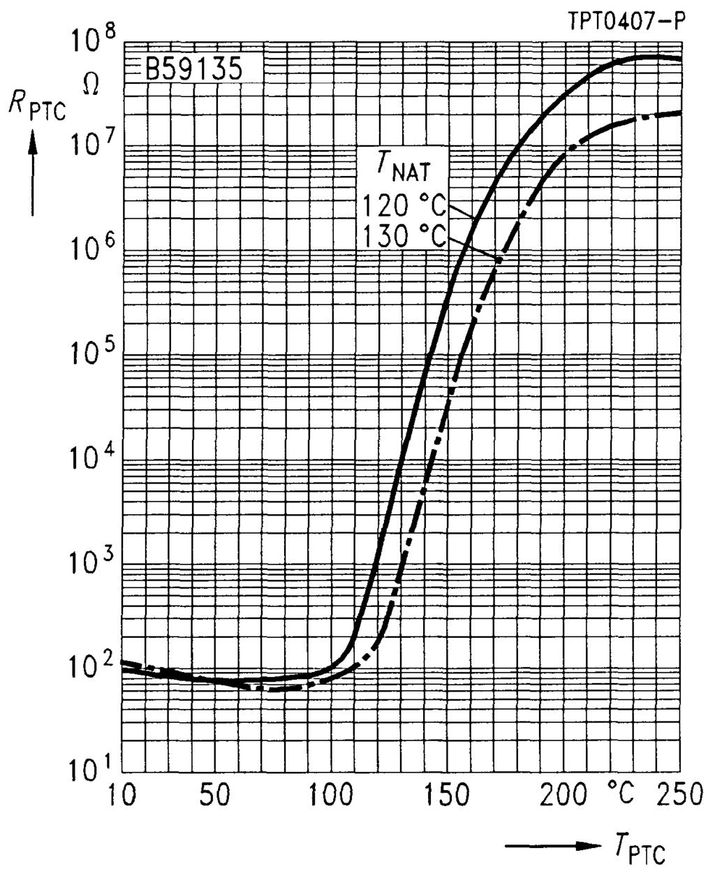
112 B59135 M 135 Characteristics (typical) PTC resistance R PTC versus PTC temperature T PTC (measured at low signal voltage) PTC resistance R PTC versus PTC temperature T PTC (measured at low signal voltage) 112 Siemens Matsushita Components

 signal voltage)")
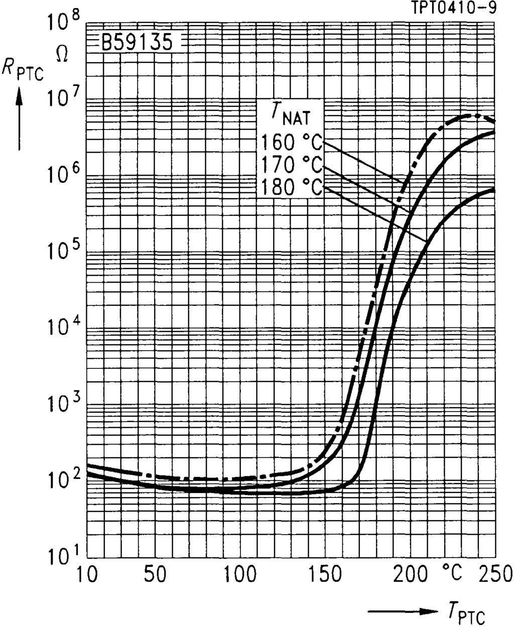
113 B59135 M 135 Characteristics (typical) PTC resistance R PTC versus PTC temperature T PTC (measured at low signal voltage) PTC resistance R PTC versus PTC temperature T PTC (measured at low signal voltage) Siemens Matsushita Components 113
114 Motor and Machine Protection B59335 M 335 Applications Thermal protection of winding in electric motors Features Thermistor pellets with insulating encapsulation in series connection (triple sensor) Low-resistance type Silver-plated and Teflon(PTFE)-insulated AWG 26 litz wires Trip temperature coded in litz wire color, connecting wires all yellow Extremely fast response due to small dimensions Characteristics for nominal threshold temperatures of 90 bis 160 conform with DIN Can be used in conjunction with Siemens tripping units Max. operating voltage (T A = 0 40 ) V max Max. measuring voltage (T A 25 K T NAT + 15 K) V Mes,max Rated resistance (V PTC 2,5 V) R N Insulation test voltage V is Response time t a Operating temperature range(v = 0) T op (V = V max ) T op 30 7, ,5 < 3 25/ /40 V V kv ac s Type T NAT ± T R (T NAT T) (V PTC 2,5 V) R (T NAT + T) (V PTC 2,5 V) R (T NAT + 15 K) (V PTC 7,5 V) R (T NAT + 23 K) (V PTC 2,5 V) M ± k M ± k M ± k M ± k M ± k M ± k M ± k M ± k M ± k M ± k M ± k M ± k M ± k M ± k M ± k 114 Siemens Matsushita Components
115 B59335 M 335 Dimensions in mm Type Color coding of litz wires Ordering code M 335 white/grey B59335-M60-A70 M 335 white/brown B59335-M70-A70 M 335 white/white B59335-M80-A70 M 335 green/green B59335-M90-A70 M 335 red/red B59335-M100-A70 M 335 brown/brown B59335-M110-A70 M 335 grey/grey B59335-M120-A70 M 335 blue/blue B59335-M130-A70 M 335 white/blue B59335-M140-A70 M 335 white/black B59335-M145-A70 M 335 black/black B59335-M150-A70 M 335 blue/black B59335-M155-A70 M 335 blue/red B59335-M160-A70 M 335 white/green B59335-M170-A70 M 335 white/red B59335-M180-A70 Siemens Matsushita Components 115
 PTC resistance R")

 116 Siemens")
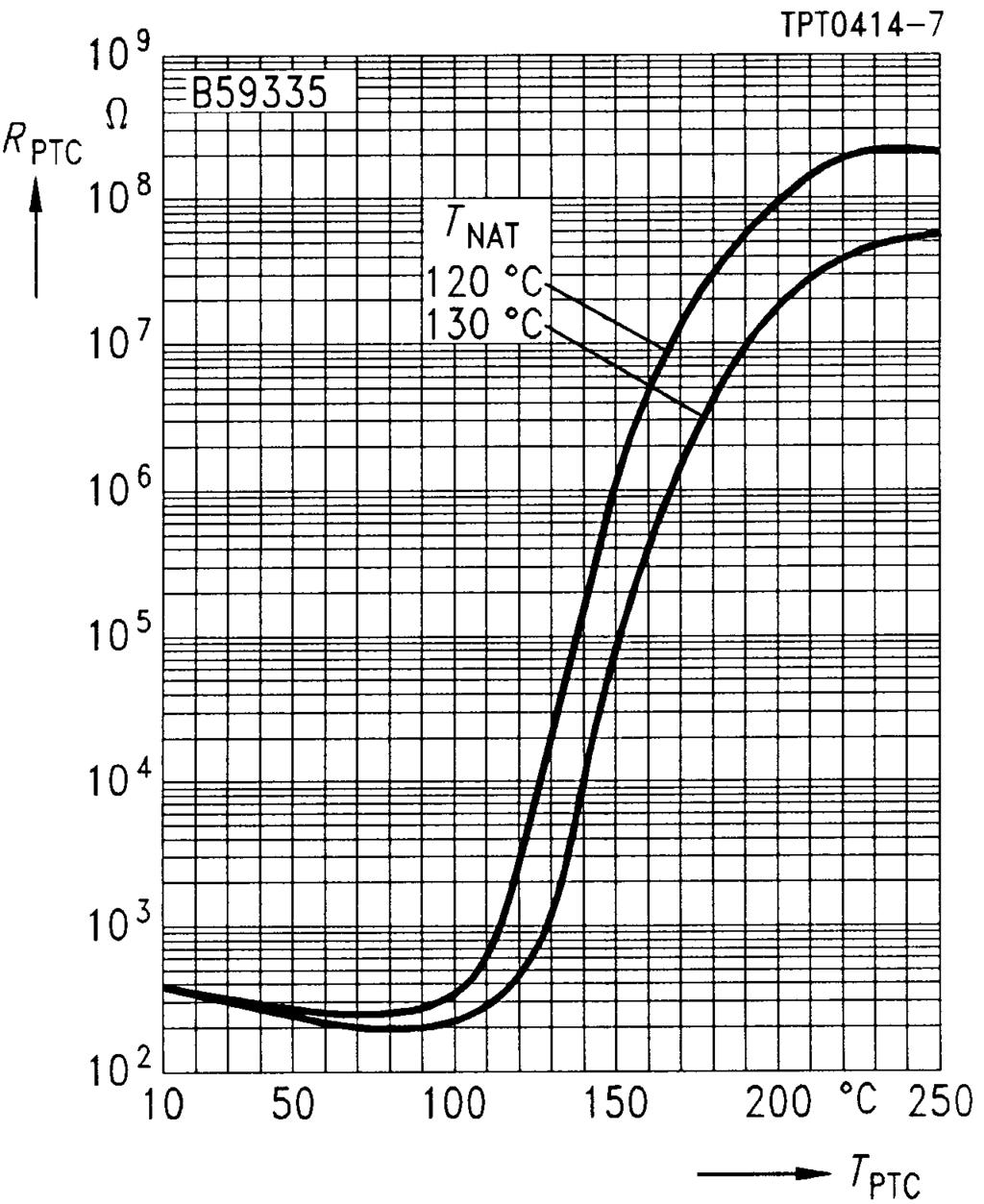
116 B59335 M 335 Characteristics (typical) PTC resistance R PTC versus PTC temperature T PTC (measured at low signal voltage) PTC resistance R PTC versus PTC temperature T PTC (measured at low signal voltage) 116 Siemens Matsushita Components

 signal voltage)")
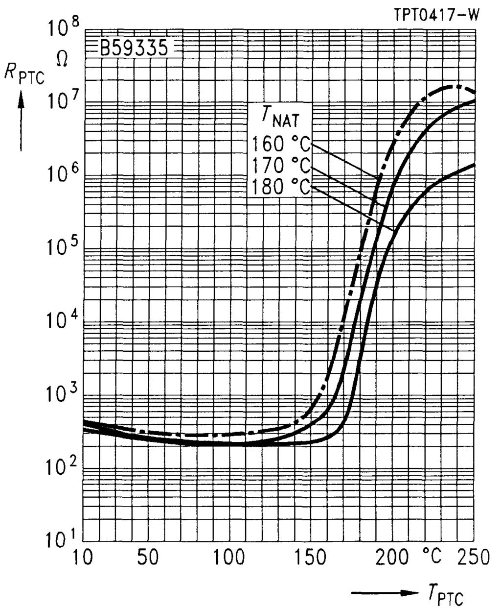
117 B59335 M 335 Characteristics (typical) PTC resistance R PTC versus PTC temperature T PTC (measured at low signal voltage) PTC resistance R PTC versus PTC temperature T PTC (measured at low signal voltage) Siemens Matsushita Components 117
118 Motor and Machine Protection B59155 M 155 Applications Thermal protection of winding in electric motors Features Thermistor pellet with insulating encapsulation Silver-plated and Teflon(PTFE)-insulated AWG 26 litz wires Trip temperature coded in litz wire color Characteristics for nominal threshold temperatures of 90 bis 160 conform with DIN Can be used in conjunction with Siemens tripping units Max. operating voltage (T A = 0 40 ) V max Max. measuring voltage (T A 25 K T NAT + 15 K) V Mes,max Rated resistance (V PTC 2,5 V) R N Insulation test voltage V is Response time t a Operating temperature range(v = 0) T op (V = V max ) T op 30 7, ,5 < 5 25/ /40 V V kv ac s Type T NAT ± T R (T NAT T) (V PTC 2,5 V) R (T NAT + T) (V PTC 2,5 V) R (T NAT + 15 K) (V PTC 7,5 V) R (T NAT + 23 K) (V PTC 2,5 V) M ± k M ± k M ± k M ± k M ± k M ± k M ± k M ± k M ± k M ± k M ± k M ± k M ± k M ± k M ± k 118 Siemens Matsushita Components
119 B59155 M 155 Dimensions in mm Type Color coding of litz wires Ordering code M 155 white/grey B59155-M60-A70 M 155 white/brown B59155-M70-A70 M 155 white/white B59155-M80-A70 M 155 green/green B59155-M90-A70 M 155 red/red B59155-M100-A70 M 155 brown/brown B59155-M110-A70 M 155 grey/grey B59155-M120-A70 M 155 blue/blue B59155-M130-A70 M 155 white/blue B59155-M140-A70 M 155 white/black B59155-M145-A70 M 155 black/black B59155-M150-A70 M 155 blue/black B59155-M155-A70 M 155 blue/red B59155-M160-A70 M 155 white/green B59155-M170-A70 M 155 white/red B59155-M180-A70 Siemens Matsushita Components 119
120 B59155 M 155 Characteristics (typical) PTC resistance R PTC versus PTC temperature T PTC (measured at low signal voltage) PTC resistance R PTC versus PTC temperature T PTC (measured at low signal voltage) 120 Siemens Matsushita Components
121 B59155 M 155 Characteristics (typical) PTC resistance R PTC versus PTC temperature T PTC (measured at low signal voltage) Siemens Matsushita Components 121
122 Motor and Machine Protection B59355 M 355 Applications Thermal protection of winding in electric motors Features Thermistor pellets with insulating encapsulation in series connection (triple sensor) Silver-plated and Teflon(PTFE)-insulated AWG 26 litz wires Trip temperature coded in litz wire color, connecting wires all in black Characteristics for nominal threshold temperatures of 90 bis 160 conform with DIN Can be used in conjunction with Siemens tripping units 3UN6 to 3UN9 Max. operating voltage (T A = 0 40 ) V max Max. measuring voltage (T A 25 K T NAT + 15 K) V Mes,max Rated resistance (V PTC 2,5 V) R N Insulation test voltage V is Response time t a Operating temperature range(v = 0) T op (V = V max ) T op 30 7, ,5 < 5 25/ /40 V V kv ac s Type T NAT ± T R (T NAT T) (V PTC 2,5 V) R (T NAT + T) (V PTC 2,5 V) R (T NAT + 15 K) (V PTC 7,5 V) R (T NAT + 23 K) (V PTC 2,5 V) M ± k M ± k M ± k M ± k M ± k M ± k M ± k M ± k M ± k M ± k M ± k M ± k M ± k M ± k M ± k 122 Siemens Matsushita Components
123 B59355 M 355 Dimensions in mm Type Color coding of litz wires Ordering code M 355 white/grey B59355-M60-A70 M 355 white/brown B59355-M70-A70 M 355 white/white B59355-M80-A70 M 355 green/green B59355-M90-A70 M 355 red/red B59355-M100-A70 M 355 brown/brown B59355-M110-A70 M 355 grey/grey B59355-M120-A70 M 355 blue/blue B59355-M130-A70 M 355 white/blue B59355-M140-A70 M 355 white/black B59355-M145-A70 M 355 black/black B59355-M150-A70 M 355 blue/black B59355-M155-A70 M 355 blue/red B59355-M160-A70 M 355 white/green B59355-M170-A70 M 355 white/red B59355-M180-A70 Siemens Matsushita Components 123

 signal voltage) 124")
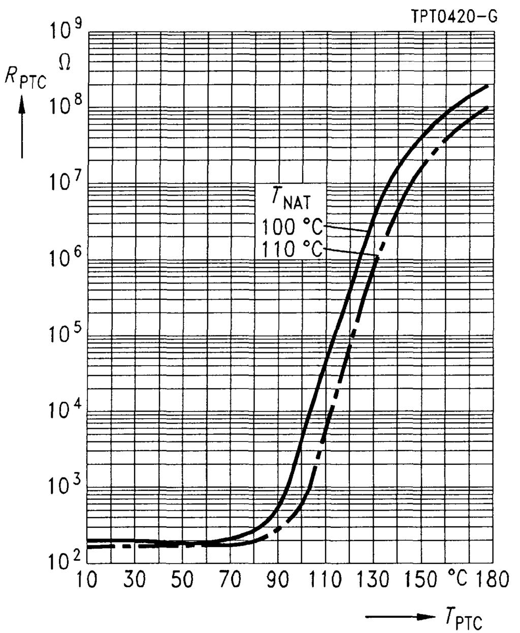
124 B59355 M 355 Characteristics (typical) PTC resistance R PTC versus PTC temperature T PTC (measured at low signal voltage) PTC resistance R PTC versus PTC temperature T PTC (measured at low signal voltage) 124 Siemens Matsushita Components

 signal voltage)")
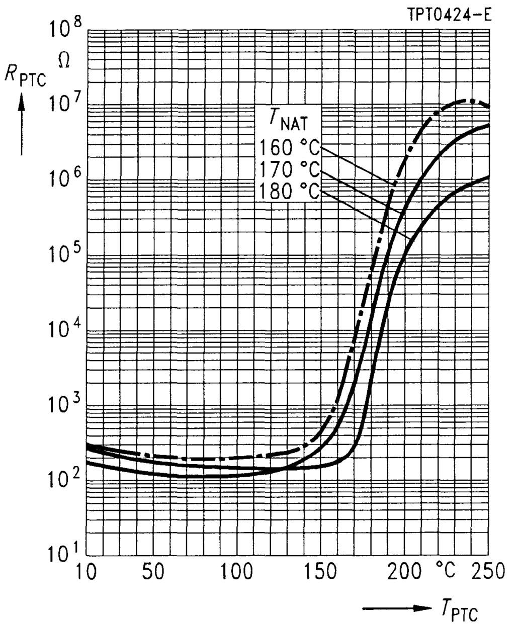
125 B59355 M 355 Characteristics (typical) PTC resistance R PTC versus PTC temperature T PTC (measured at low signal voltage) PTC resistance R PTC versus PTC temperature T PTC (measured at low signal voltage) Siemens Matsushita Components 125
126 Level Sensors Q63100-P430 E 11 Applications Liquid level detection, e. g. for overflow protection in oil tanks Features Hermetically sealed glass case Marked with date of manufacture Example: 11 B 3 G = = March Solderability complies with IEC TÜV approval Dimensions (mm) Type E 11 Max. operating voltage V max Rated resistance R N ± R Pressure test p Operating temperature range (V = 0 V) T op (V = 24 V) T op Number of cycles (R V = 100 ) N Residual current in oil (V = 12 V, T A = 50 ) I r,oil Residual current in air (V = 14 V, T A = 25 ) I r,air Minimum resistance (V = 24 V) R min Switching time t S Settling time t E Surface temperature (V = 24 V) T surf Ordering code Q63100-P430-E ± / / , < 200 V bar ma ma s s 126 Siemens Matsushita Components
127 Q63100-P430 E 11 Test set-up Clamp Contact spring Thermistor pellet Unclipped leads, held at the ends by clamps Sensor in vertical position Distance of clamping point to body: min. 22 mm Pellet points downwards Settling time after application of voltage: min. 40 s Clamp Limits of operating range Operating range in oil Signal range Operating range in air Siemens Matsushita Components 127
128 Level Sensors B59020 E 1020 Applications Liquid level detection Features Hermetically sealed glass case Marked with type designation and manufacturer s logo Solderability complies with IEC ESD packing Dimensions (mm) Type E 1020 Max. operating voltage V max Rated resistance R N ± R Operating temperature range (V = 0 V) T op (V = 24 V) T op Number of cycles (R V = 110 ) N Residual current in oil (R V = 110, V = 18 V, T A = 50 ) I r,oil Residual current in air (R V = 110, V = 18 V, T A = 25 ) I r,air Minimum resistance (V = 24 V) R min Switching time t S Settling time t E Surface temperature (V = 24 V) T surf Ordering code B59020-E1160-A ± 35 55/ / ,7 26, < 200 V ma ma s s 128 Siemens Matsushita Components
129 B59020 E 1020 Test set-up Clamp Contact spring Thermistor pellet Unclipped leads, held at the ends by clamps Sensor in vertical position Distance of clamping point to body: min. 22 mm Pellet points downwards Settling time after application of voltage: min. 40 s Clamp Siemens Matsushita Components 129
130 Level Sensors B59010 D 1010 Applications Liquid level detection in tanks (oil, gas, etc.) and household appliances Features Hermetically sealed stainless steel case (withstands liquid pressure of up to 10 bar) Solderability complies with IEC Rust- and acid-resistant in accordance with DIN Dimensions (mm) Type D 1010 Max. operating voltage V max Rated resistance R 25 Pressure test p Operating temperature range (V = 0 V) T op (V = 24 V) T op Number of cycles (R V = 100, V = V max ) N Residual current in oil (V = 12 V, T A = 50 ) I r,oil Residual current in air (V = 14 V, T A = 25 ) I r,air Minimum resistance (V = 24 V) R min Switching time t S Settling time t E Surface temperature (V = 24 V) T surf Ordering code B59010-D1135-B / / , < 200 V bar ma ma s s 130 Siemens Matsushita Components
131 B59010 D 1010 Test set-up Clamp Unclipped leads, held at the ends by clamps Sensor in vertical position Distance of clamping point to body: min. 15 mm Pellet points downwards Settling time after application of voltage: min. 40 s Limits of operating range Operating range in oil Signal range Operating range in air Siemens Matsushita Components 131
132 Measurement and Control Disks B59011 C V Applications General-purpose usage in temperature measurement and control Limit temperature monitoring Features Coated thermistor disk Tinned leads Marked with stamp Options Also available on tape Dimensions (mm) Max. operating voltage V max Tolerance of rated resistance R 1 N ) Response time t a Operating temperature range (V = 0) T op (V = V max ) T op 30 ± 25 % < 5 25/ /60 V s Type T Ref ± T R N R Ref R (T Ref T) R (T Ref + T) R min C ) 30 ± 5 > 100 k C ) 0 ± 5 > C ± C ± C ± C ± C ± C ± ) R N = ± 25 % not valid for B59011-C1930-A70 and B59011-C1000-A Siemens Matsushita Components
 Ordering code ma C 1011 45 70 40 200 k B59011-C1930-A70 C 1011 50 40 60 200 k B59011-C1000-A70 C 1011")

133 B59011 C 1011 Characteristics (typical) PTC resistance R PTC versus PTC temperature T PTC (measured at low signal voltage) Type I max T Rmin T PTC R (T PTC ) Ordering code ma C k B59011-C1930-A70 C k B59011-C1000-A70 C k B59011-C1040-A70 C k B59011-C1060-A70 C k B59011-C1080-A70 C k B59011-C1120-A70 C k B59011-C1160-A70 C k B59011-C1180-A70 Siemens Matsushita Components 133
134 Measurement and Control Disks B59012 C V Applications General-purpose usage in temperature measurement and control Limit temperature monitoring Features Coated thermistor disk Tinned leads Marked with stamp Suitable for automatic insertion Options Also available on tape Dimensions (mm) Max. operating voltage V max Tolerance of rated resistance R N Response time t a Operating temperature range (V = 0) T op (V = V max ) T op 265 ± 25 % < 10 25/ /60 V s Type T Ref ± T R N R Ref R (T Ref T) R (T Ref + T) R min C ± C ± C ± C ± C ± C ± Siemens Matsushita Components
 Type I max T Rmin T PTC R (T PTC ) Ordering code A C 1012 0,3 0 115 10 k B59012-C1040-A70 C")

135 B59012 C 1012 Characteristics (typical) PTC resistance R PTC versus PTC temperature T PTC (measured at low signal voltage) Type I max T Rmin T PTC R (T PTC ) Ordering code A C , k B59012-C1040-A70 C , k B59012-C1060-A70 C , k B59012-C1080-A70 C , k B59012-C1120-A70 C , k B59012-C1160-A70 C , k B59012-C1180-A70 Siemens Matsushita Components 135
136 Measurement and Control Disks B59013 C V Applications General-purpose usage in temperature measurement and control Limit temperature monitoring Features Coated thermistor disk Tinned leads Marked with stamp Suitable for automatic insertion Options Also available on tape Dimensions (mm) Max. operating voltage V max Tolerance of rated resistance R N Response time t a Operating temperature range (V = 0) T op (V = V max ) T op 265 ± 25 % < 20 25/ /60 V s Type T Ref ± T R N R Ref R (T Ref T) R (T Ref + T) R min C ± C ± C ± C ± C ± C ± Siemens Matsushita Components
 Type I max T Rmin T PTC R (T PTC ) Ordering code A C 1013 1 0 115 4 k B59013-C1040-A70 C")

137 B59013 C 1013 Characteristics (typical) PTC resistance R PTC versus PTC temperature T PTC (measured at low signal voltage) Type I max T Rmin T PTC R (T PTC ) Ordering code A C k B59013-C1040-A70 C k B59013-C1060-A70 C k B59013-C1080-A70 C k B59013-C1120-A70 C k B59013-C1160-A70 C k B59013-C1180-A70 Siemens Matsushita Components 137
138 Measurement and Control Disks B59008 C 8 30 V Applications Sensor for small measuring points Limit temperature monitoring Features Coated thermistor disk Tinned leads Marked with coded nominal threshold temperature Characteristics for nominal threshold temperatures of 90 to 160 conform with DIN Extremely fast response due to small dimensions Dimensions (mm) Max. operating voltage (T A = 0 40 ) V max Max. measuring voltage (T A 25 K T NAT + 15 K) V Meas,max Rated resistance (V PTC 2,5 V) R N Response time t a Operating temperature range(v = 0) T op (V = V max ) T op 30 7,5 250 < 3 25/ /40 V V s Type/ Stamp code T NAT ± T R 1 ) (T NAT T) R 1 ) (T NAT + T) R 2 ) (T NAT + 15 K) R 1 ) Ordering code (T NAT + 23 K) C 8 f 60 ± k B59008-C60-A40 C 8 g 70 ± k B59008-C70-A40 C 8 h 80 ± k B59008-C80-A40 C 8 i 90 ± k B59008-C90-A40 C 8 j 100 ± k B59008-C100-A40 C 8 k 110 ± k B59008-C110-A40 C 8 l 120 ± k B59008-C120-A40 C 8 m 130 ± k B59008-C130-A40 C 8 n 140 ± k B59008-C140-A40 C 8 o 145 ± k B59008-C145-A40 C 8 p 150 ± k B59008-C150-A40 C 8 r 155 ± k B59008-C155-A40 C 8 s 160 ± k B59008-C160-A40 C 8 t 170 ± k B59008-C170-A40 C 8 u 180 ± k B59008-C180-A40 1 ) V PTC 2,5 V 2 ) V PTC 7,5 V 138 Siemens Matsushita Components
 PTC resistance R")

 Siemens Matsushita")
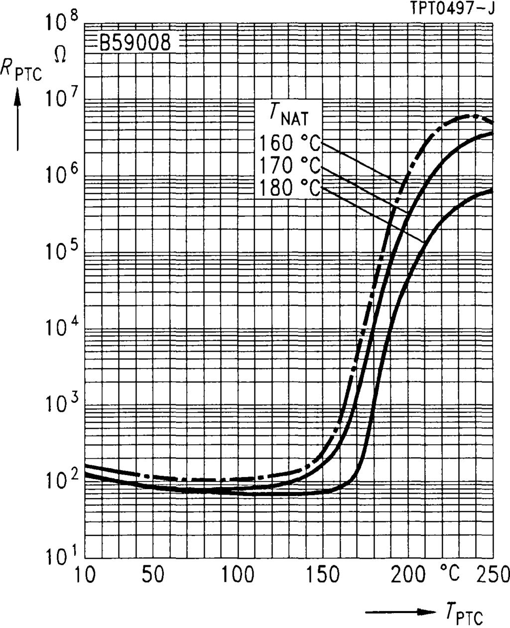
139 B59008 C 8 Characteristics (typical) PTC resistance R PTC versus PTC temperature T PTC (measured at low signal voltage) PTC resistance R PTC versus PTC temperature T PTC (measured at low signal voltage) Siemens Matsushita Components 139
140 Measurement and Control Disks B59100 C V Applications Sensor for small measuring points Limit temperature monitoring Features Coated thermistor disk Tinned leads Manufacturer s logo and type designation stamped on in white Characteristics for nominal threshold temperatures of 90 to 160 conform with DIN Also available on tape Dimensions (mm) Max. operating voltage (T A = 0 40 ) V max Max. measuring voltage (T A 25 K T NAT + 15 K) V Meas,max Rated resistance (V PTC 2,5 V) R N Response time t a Operating temperature range(v = 0) T op (V = V max ) T op 30 7,5 100 < 5 25/ /40 V V s Type T NAT ± T R 1 ) (T NAT T) R 1 ) (T NAT + T) R 2 ) (T NAT + 15 K) R 1 ) Ordering code (T NAT + 23 K) C ± k B59100-C60-A70 C ± k B59100-C70-A70 C ± k B59100-C80-A70 C ± k B59100-C90-A70 C ± k B59100-C100-A70 C ± k B59100-C110-A70 C ± k B59100-C120-A70 C ± k B59100-C130-A70 C ± k B59100-C140-A70 C ± k B59100-C145-A70 C ± k B59100-C150-A70 C ± k B59100-C155-A70 C ± k B59100-C160-A70 C ± k B59100-C170-A70 C ± k B59100-C180-A70 1 ) V PTC 2,5 V 2 ) V PTC 7,5 V 140 Siemens Matsushita Components
 PTC resistance R")

 Siemens Matsushita")
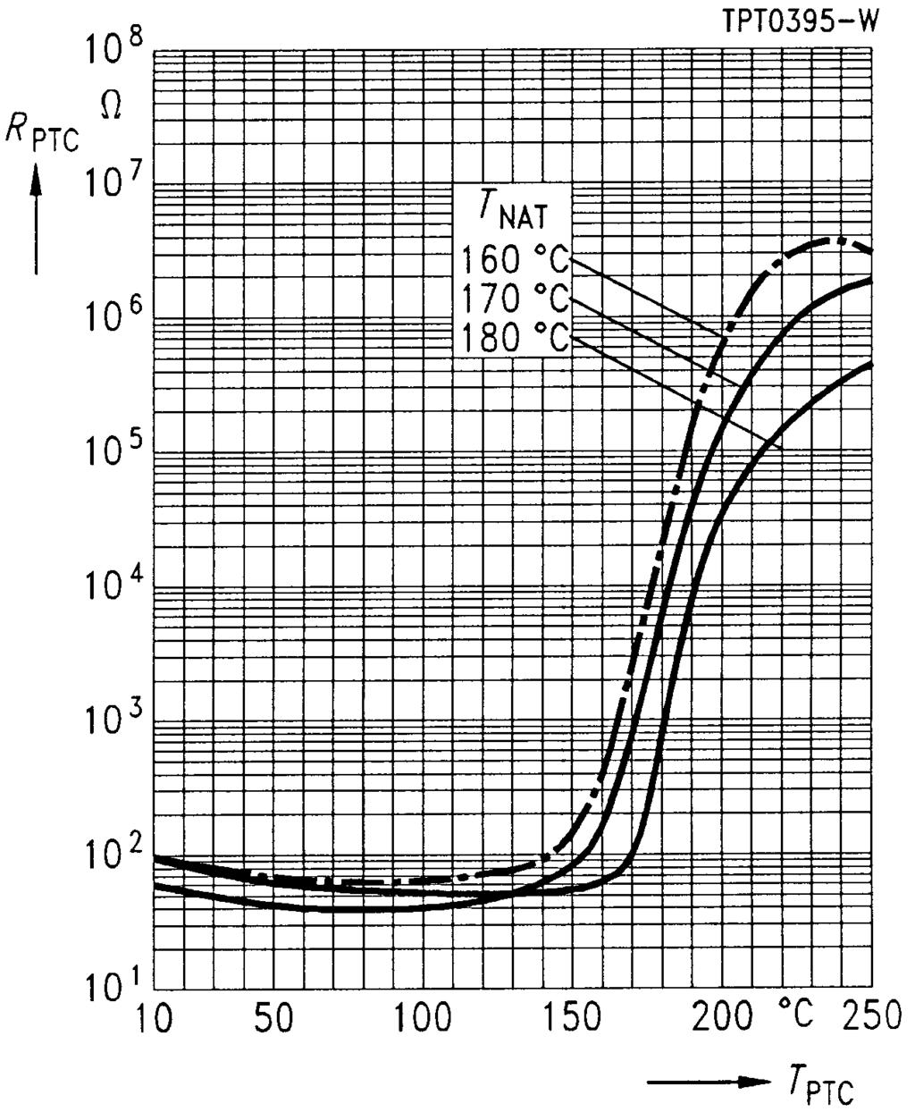
141 B59100 C 100 Characteristics (typical) PTC resistance R PTC versus PTC temperature T PTC (measured at low signal voltage) PTC resistance R PTC versus PTC temperature T PTC (measured at low signal voltage) Siemens Matsushita Components 141
142 Measurement and Control Probe Assemblies B59401 D V Applications Limit temperature sensor in screw-type case Features Insulated screw-type metal case, thread M4 Tinned leads Color-coded sealing with black dot Case permits good thermal coupling Dimensions (mm) Max. operating voltage V max Tolerance of rated resistance R N Insulation test voltage V is Response time t a Operating temperature range(v = 0) T op (V = V max ) T op / 25 % 3 < 50 25/ /60 V kv ac s Type T Ref ± T R N R Ref R (T Ref T) R (T Ref + T) R min D ± D ± D ± D ± D ± Siemens Matsushita Components
143 B59401 D 401 Characteristics (typical) PTC resistance R PTC versus PTC temperature T PTC (measured at low signal voltage) Type I max ma T Rmin T PTC R (T PTC ) Color of sealing Ordering code D k blue B59401-D40-A40 D k violet B59401-D60-A40 D k orange B59401-D80-A40 D k clear B59401-D90-A40 D k green B59401-D120-A40 Siemens Matsushita Components 143
144 Measurement and Control Probe Assemblies B59801 D V Applications Limit temperature sensor Features Insulated screw-type metal case Thread M3 Tinned leads Marked with nominal threshold temperature and type designation Characteristics for nominal threshold temperatures of 90 to 160 conform with DIN Fast response due to small dimensions Dimensions (mm) Max. operating voltage (T A = 0 40 ) V max Max. measuring voltage (T A 25 K T NAT + 15 K) V Meas,max Rated resistance (V PTC 2,5 V) R N Insulation test voltage V is Response time (T NAT 20 K T NAT + 15 K)t a Operating temperature range(v = 0) T op (V = V max ) T op 30 7, ,5 < 20 25/ /40 V V kv ac s Type T NAT ± T R 1 ) (T NAT T) R 1 ) (T NAT + T) R 2 ) (T NAT + 15 K) R 1 ) Ordering code (T NAT + 23 K) D ± k B59801-D60-A70 D ± k B59801-D70-A70 D ± k B59801-D80-A70 D ± k B59801-D90-A70 D ± k B59801-D100-A70 D ± k B59801-D110-A70 D ± k B59801-D120-A70 D ± k B59801-D130-A70 D ± k B59801-D140-A70 D ± k B59801-D145-A70 D ± k B59801-D150-A70 D ± k B59801-D155-A70 D ± k B59801-D160-A70 1 ) V PTC 2,5 V 2 ) V PTC 7,5 V 144 Siemens Matsushita Components
 PTC resistance R PTC versus PTC temperature T PTC (measured at low signal voltage) Siemens Matsushita")
145 B59801 D 801 Characteristics (typical) PTC resistance R PTC versus PTC temperature T PTC (measured at low signal voltage) PTC resistance R PTC versus PTC temperature T PTC (measured at low signal voltage) Siemens Matsushita Components 145
146 Measurement and Control Probe Assemblies B59901 D V Applications Limit temperature sensor Features Sensor with epoxy resin coating Tinned leads Metal tag for easy mounting Characteristics for nominal threshold temperatures of 90 to 160 conform with DIN Metal tag permits good thermal coupling and thus short response times Dimensions (mm) Max. operating voltage (T A = 0 40 ) V max Max. measuring voltage (T A 25 K T NAT + 15 K) V Meas,max Rated resistance (V PTC 2,5 V) R N Response time t a Operating temperature range(v = 0) T op (V = V max ) T op 30 7,5 100 < 20 25/ /40 V V s Type/ Stamp code T NAT ± T R 1 ) (T NAT T) R 1 ) (T NAT + T) R 2 ) (T NAT + 15 K) R 1 ) (T NAT + 23 K) Ordering code D ± k B59901-D60-A40 D ± k B59901-D70-A40 D ± k B59901-D80-A40 D ± k B59901-D90-A40 D ± k B59901-D100-A40 D ± k B59901-D110-A40 D ± k B59901-D120-A40 D ± k B59901-D130-A40 D ± k B59901-D140-A40 1 ) V PTC 2,5 V 2 ) V PTC 7,5 V 146 Siemens Matsushita Components
147 B59901 D 901 Characteristics (typical) PTC resistance R PTC versus PTC temperature T PTC (measured at low signal voltage) PTC resistance R PTC versus PTC temperature T PTC (measured at low signal voltage) Siemens Matsushita Components 147
148 Measurement and Control SMDs B59701 A V Applications Limit temperature sensor Features Thermistor chip with silver terminations Very small size Fast and reliable response Suitable for reflow soldering, also for conductive adhesion Suitable for automatic placement Available on 8-mm blister tape (standard delivery mode) Termination Dimensions (mm) Max. operating voltage (T A = 0 40 ) V max Max. measuring voltage (T A 25 K T NAT + 15 K) V Meas,max Rated resistance (V PTC 2,5 V) R N Operating temperature range(v = 0) T op (V = V max ) T op 25 7,5 1 25/ /40 V V k Type T NAT ± T R 1 ) (T NAT T) k R 1 ) (T NAT + T) k R 2 ) (T NAT + 15 K) k Ordering code A ± 5 5,5 13,3 40 B59701-A1090-A62 A ± 5 5,5 13,3 40 B59701-A1100-A62 A ± 5 5,5 13,3 40 B59701-A1110-A62 A ± 5 5,5 13,3 40 B59701-A1120-A62 A ± 5 5,5 13,3 40 B59701-A1130-A62 1 ) V PTC 2,5 V 2 ) V PTC 7,5 V 148 Siemens Matsushita Components
 Siemens Matsushita")
149 B59701 A 1701 Characteristics (typical) PTC resistance R PTC versus PTC temperature T PTC (measured at low signal voltage) Siemens Matsushita Components 149
150 Heating Elements and Thermostats B59060 A V Applications Heating element for small heating systems, e. g. in automobiles Features Thermistor disk with silver metallization on front surfaces Suitable for clamp-contacting and glue-bonding Curvature < 0,2 mm Termination Dimensions (mm) Max. operating voltage V max Rated voltage V N Breakdown voltage V D Operating temperature range (V = 0) T op (V = V N ) T op Resistance tolerance R > 36 40/ /+ 60 ± 30 % 1 ) V V V Type T Ref R min (V = V N ) T surf 3 ) (V = V N ) R N (V Meas 1,5 V) Ordering code A ) B59060-A-A10 A ) 70 9 B59060-A40-A10 A B59060-A60-A10 A B59060-A80-A10 A B59060-A120-A10 A B59060-A160-A10 A B59060-A180-A10 A B59060-A220-A10 A B59060-A280-A10 1 ) Tolerance not valid for B59060-A-A10 2 ) Valid for T A < 25 3 ) Measured peak-to-peak 150 Siemens Matsushita Components
 Siemens Matsushita")
151 B59060 A 60 Characteristics (typical) PTC resistance R PTC versus PTC temperature T PTC (measured at low signal voltage) Siemens Matsushita Components 151
152 Heating Elements and Thermostats B59042 R V Applications General-purpose heating element, e. g. for automotive applications Features Thermistor plate with aluminum metallization No migration effects For clamp-contacting Max. curvature 0,05 mm Options Other dimensions available upon request 37,2 max Termination Dimensions (mm) 6,4 max Max. operating voltage V max Rated voltage V N Breakdown voltage V D Operating temperature range (V = 0) T op (V = V N ) T op Resistance tolerance R > 40 40/ /+ 60 ± 50 % V V V Type T Ref R min (V = V N ) T surf 2 ) (V = V N ) R N (V Meas 1,5 V) Ordering code R 1042-A ,00 1 ) 75 3,2 B59042-R1040-A10 R 1042-A , ,2 B59042-R1060-A10 R 1042-A , ,2 B59042-R1080-A10 R 1042-A , ,2 B59042-R1120-A10 R 1042-A , ,2 B59042-R1160-A10 R 1042-A , ,2 B59042-R1180-A10 R 1042-A , ,4 B59042-R1220-A10 R 1042-A , ,8 B59042-R1280-A10 1 ) Valid for T A < 25 2 ) Measured peak-to-peak 152 Siemens Matsushita Components
153 B59042 R 1042 Characteristics (typical) PTC resistance R PTC versus PTC temperature T PTC (measured at low signal voltage) Siemens Matsushita Components 153
154 Heating Elements and Thermostats B59053 A V Applications Self-regulating heating element Features Thermistor disk with silver metallization on front surfaces High electric strength Suitable for clamp-contacting and glue-bonding Curvature < 0,2 mm Termination Dimensions (mm) Max. operating voltage V max Rated voltage V N Breakdown voltage (T A = 25 ) V D Operating temperature range (V = 0) T op (V = V N ) T op Resistance tolerance R / /60 ± 35 % V V V Type T Ref R min (V = V N ) T surf 2 ) (V = V N ) R N (V Meas 1,5 V) Ordering code A ) B59053-A50-A10 A B59053-A70-A10 A B59053-A90-A10 A B59053-A110-A10 A B59053-A130-A10 A B59053-A150-A10 A B59053-A180-A10 A B59053-A220-A10 A B59053-A270-A10 1 ) Valid for T A < 25 2 ) Measured peak-to-peak 154 Siemens Matsushita Components
155 B59053 A 53 Characteristics (typical) PTC resistance R PTC versus PTC temperature T PTC (measured at low signal voltage) Siemens Matsushita Components 155
156 Heating Elements and Thermostats B59066 A V Applications Self-regulating heating element Features Thermistor disk with aluminum metallization on front surfaces No migration effects Suitable for clamp-contacting Curvature < 0,2 mm Termination Dimensions (mm) Max. operating voltage V max Rated voltage V N Operating temperature range (V = 0) T op (V = V N ) T op Resistance tolerance R / /60 ± 35 % V V Type V D V T Ref R min (V = V N ) T surf 2 ) (V = V N ) R N (V Meas 1,5 V) Ordering code A ) B59066-A50-A10 A B59066-A70-A10 A B59066-A90-A10 A B59066-A110-A10 A B59066-A130-A10 A B59066-A150-A10 A B59066-A180-A10 A B59066-A220-A10 A B59066-A270-A10 1 ) Valid for T A < 25 2 ) Measured peak-to-peak 156 Siemens Matsushita Components
157 B59066 A 66 Characteristics (typical) PTC resistance R PTC versus PTC temperature T PTC (measured at low signal voltage) Siemens Matsushita Components 157
158 Heating Elements and Thermostats B59102 R V Applications Self-regulating heating element Features Thermistor disk with aluminum metallization on front surfaces No migration effects Suitable for clamp-contacting Curvature < 0,05 mm Options Other dimensions available upon request 37,2 max Termination Dimensions (mm) 6,4 max Max. operating voltage V max Rated voltage V N Operating temperature range (V = 0) T op (V = V N ) T op Resistance tolerance R / /60 ± 50 % V V Type V D V T Ref R min (V = V N ) T surf 2 ) (V = V N ) R N (V Meas 1,5 V) Ordering code R ) B59102-R50-A10 R B59102-R70-A10 R B59102-R90-A10 R B59102-R110-A10 R B59102-R130-A10 R B59102-R150-A10 R B59102-R180-A10 R B59102-R220-A10 R B59102-R240-A10 R B59102-R270-A10 R B59102-R290-A10 1 ) Valid for T A < 25 2 ) Measured peak-to-peak 158 Siemens Matsushita Components
159 B59102 R 102 Characteristics (typical) PTC resistance R PTC versus PTC temperature T PTC (measured at low signal voltage) PTC resistance R PTC versus PTC temperature T PTC (measured at low signal voltage) Siemens Matsushita Components 159

160 S+M COMPONENTS Siemens Matsushita Components Ferrite inductors from SCS stock Transformation at its best Not just one-off solutions but complete ones designed precisely to a requirements profile are more in demand than ever. So we are offering surface-mount transformers for power and broadband applications straight from SCS stock: E 6,3 with small dimensions, low leakage inductance and high electric strength ER 11 flat and with low leakage inductance RM 4 LP for high DC biasing S interface transformer RM 5 for precise pulse transmission in ISDN terminals U interface transformer RM 6 for ISDN applications Planar inductor RM 7 with high power density and extremely flat for DC/DC applications SCS dependable, fast and competent
161 Mounting Instructions 1 Soldering 1.1 Leaded PTC thermistors Leaded PTC thermistors comply with the solderability requirements specified by CECC. When soldering, care must be taken that the thermistors are not damaged by excessive heat. The following maximum temperatures, maximum time spans and minimum distances have to be observed: Dip soldering Iron soldering Bath temperature max. 260 C max. 360 C Soldering time max. 4 s max. 2 s Distance from thermistor min. 6 mm min. 6 mm Under more severe soldering conditions the resistance may change. Mounting Instructions 1.2 Leadless PTC thermistors In case of PTC thermistors without leads, soldering is restricted to devices which are provided with a solderable metallization. The temperature shock caused by the application of hot solder may produce fine cracks in the ceramic, resulting in changes in resistance. To prevent leaching of the metallization, solder with silver additives or with a low tin content should be used. In addition, soldering methods should be employed which permit short soldering times. 1.3 SMD PTC thermistors The notes on soldering leadless thermistors also apply to the SMD versions (see IEC ) Wettability test in accordance with IEC Preconditioning: Immersion into flux F-SW 32. Evaluation criterion: Wetting of soldering areas 95 %. Termination Solder Bath temperature () Dwell time (s) PTC CrNiAg SnPb or SnPbAg 215 ± /40 62/36/2 Siemens Matsushita Components 161
162 Mounting Instructions Soldering heat resistance test in accordance with IEC Preconditioning: Immersion into flux F-SW 32. Evaluation criterion: Leaching of side edges 1/3. Termination Solder Bath temperature () Dwell time (s) PTC CrNiAg SnPb or SnPbAg 260 ± /40 62/36/2 Note: PTC thermistors in sizes 3225 and 4032 do not have metallized pads, but metal-strip terminations Recommended soldering temperature profiles Vapor phase soldering Temperature/time diagram for vapor phase soldering, in-line system with preheating. The temperatures stated refer to the component terminals. 162 Siemens Matsushita Components
163 Mounting Instructions Wave soldering Temperature on the component terminals during dual wave soldering Infrared soldering Temperature on the component terminals during infrared soldering Siemens Matsushita Components 163
164 Mounting Instructions Notes: When soldering large components ( size1210) care must be taken that the temperature jump between preheating and soldering wave will not exceed 100 K. Iron soldering should be avoided, hot air methods are recommended for repair purposes. 2 Conductive adhesion An alternative to soldering is the gluing of thermistors with conductive adhesives. The benfit of this method is that it involves no thermal stress. The adhesives used must be chemically inert. 3 Clamp contacting Pressure contacting by means of clamps is particularly suitable for applications involving frequent switching and high turn-on powers. PTC thermistors for heating and motor starting have metallized surfaces for clamp contacting. 4 Robustness of terminations The leads meet the requirements of IEC They may not be bent closer than 4 mm from the solder joint on the thermistor body or from the point at which they leave the feed-throughs. During bending, any mechanical stress at the outlet of the leads must be removed. The bending radius should be at least 0,75 mm. Tensile strength: Test Ua1: Leads 0,5 mm = 5 N > 0,5 mm = 10 N Bending strength: Test Ub: Two 90 -bends in opposite directions at a weight of 0,25 kg. Torsional strength: Test Uc: severity 2 The lead is bent by 90 at a distance of 6 to 6,5 mm from the thermistor body. The bending radius of the leads should be approx. 0,75 mm. Two torsions of 180 each (severity 2). When subjecting leads to mechanical stress, the following should be observed: Tensile stress on leads During mounting and operation tensile forces on the leads are to be avoided. Bending of leads Bending of the leads directly on the thermistor body is not permissible. A lead may be bent at a minimum distance of twice the wire s diameter + 2 mm from the solder joint on the thermistor body. During bending the wire must be mechanically relieved at its outlet. The bending radius should be at least 0,75 mm. Twisting of leads The twisting (torsion) by 180 of a lead bent by 90 is permissible at 6 mm from the bottom of the thermistor body. 164 Siemens Matsushita Components
165 Mounting Instructions 5 Sealing and potting When thermistors are sealed or potted, there must be no mechanical stress through differing thermal expansion in the curing process and during later operation. In the curing process the upper category temperature of the thermistor must not be exceeded. It is also necessary to ensure that the potting compound is chemically neutral. Sealing and potting compounds may reduce the titanate ceramic of PTC thermistors and lead to the formation of low-ohmic conduction bridges. In conjunction with a change in dissipation conditions due to the potting compound, local overheating may finally damage the thermistor. 6 Cleaning If cleaning is necessary, mild cleaning agents such as freon, trichloroethane and perchloroethylene are recommended. Ultrasonic cleaning methods are permissible. 7 Storage In order to maintain their solderability, thermistors must be stored in a non-corrosive atmosphere. Humidity, temperature and container materials are critical factors. If possible, the components should be left in the original packing. Touching the metallization of unsoldered thermistors may change their soldering properties. Siemens Matsushita Components 165

166 S+M COMPONENTS Siemens Matsushita Components Siemens filters from stock Ready, steady, go SCS has 100,000 SIFI filters in stock, ready to go as soon as your order arrives. We offer a big selection through all the many variants, ie building-block system, different attenuation characteristics and packages, various kinds of leads and current ratings from 1 through 20 A. SCS dependable, fast and competent
167 Quality 1 Manufacturing process and quality assurance Manufacturing process Quality assurance Quality Incoming goods Quality gate Inspection of raw materials and parts Weighing Milling Specific surface, grain size Testing and final inspection Assembly Preproduction Pre-sintering Granulation Pressing Sintering Metallization Grouping by resistance Soldering Coating, assembly, finish Final measurement Conformance test Packing Warehouse Quality gate Quality gate Powder release (vis., mech., el. inspection) Humidity, grain size distribution Weight, dimensions Sinter release (vis., mech., el. inspection) Resistance, layer thickness Resistance, B value Visual inspection, pull-off strength Visual inspection, dimensions Resistance Sampling inspection (mech., el. parameters) Quality gate Identity Dispatch Siemens Matsushita Components 167
168 Quality 2 General S + M has set up extensive quality assurance systems in order to meet the stringent technical demands of an open world market. These systems follow the CECC ISO-9000 to ISO-9004 standards. Our QA system received the ISO 9001 certificate in September Sequence of quality assurance measures The quality department tested and released the PTC thermistors described in this data book on the basis of the following criteria: compliance with type specifications, process capability of production equipment as well as accuracy of measuring and test methods and equipment. To ensure a constantly high quality level, the following tests are carried out: 3.1 Incoming inspection The parts and materials required for production are checked for dimensional accuracy and material properties in a prescribed sequence. 3.2 Process assurance To achieve the objective of eliminating defects as efficiently as possible and at their very source, quite different measures are taken. Modern quality tools such as FMEA (Failure Mode and Effect Analysis) are used already during the starting phase: A risk-priority figure is assigned to potential defects according to their significance as well as to the probability of occurrence and detection. In case of high risk-priority figures, remedial measures are taken from the beginning. During production all essentail processes are subject to statistical process control (SPC). 3.3 Product assurance Each manufacturing stage is followed by a socalled quality control gate, i.e. the product is only released for the next stage after passing a corresponding test. The test results are constantly monitored and evaluated and are then used to assess the quality of the manufacturing process itself (refer to 3.2). 3.4 Final inspection During final inspection, specification-based parameters are checked in conformance tests. 4 Delivery quality The term delivery quality designates the conformance with agreed data at the time of delivery. 168 Siemens Matsushita Components
169 Quality 5 Sampling inspection The customer may carry out incoming inspections which are subject to standardized sampling inspection plans specifying the acceptance or rejection of a delivery lot in conjunction with agreed AQL values (AQL = acceptable quality level). The scope and the maximum permissible number of defects of a sampling inspection are specified in IEC 410 (identical with MIL-STD 105 D and DIN ISO ), single sampling plan for normal inspection, inspection level II. The sampling instructions of this standard are such that a delivered lot will be accepted with a high degree of probability (greater than 90 %), if the percentage of defectives does not exceed the specified AQL level. Generally, the average defect percentage of our deliveries lies clearly below the AQL value. This is ensured by appropriate quality assurance measures in the manufacturing plants and substantiated by the final inspections. 6 Classification of defects A component is considered defective if it does not comply with the specifications stated in the data sheets or in an agreed delivery specification. Defects which generally exclude the functional use of the component (inoperatives) are classified separately from less significant defects. Inoperatives of thermistors are: Short circuit or open circuit Component, case, terminals or encapsulation broken Incorrect marking Mixing of different types Other defects are: Electrical defects (maximum ratings are exceeded) Mechanical defects, e. g. incorrect dimensions, damaged housings, illegible marking, twisted leads 7 AQL values The following AQL values apply to the quoted defects for inoperatives (electrical and mechanical) 0,065 for the total number of electrical defectives 0,250 for the total number of mechanical defectives 0,250 The values for the total number of defectives include related inoperatives. Siemens Matsushita Components 169
170 Quality 8 Incoming inspection by the customer The quality of our products is ensured by the QA measures assigned to the individual production stages as shown on page 167. Thus the customer can do away with cost-intensive incoming inspections. If a customer wishes nevertheless to carry out an incoming inspection, we recommend that the inspection plan shown below is used. The inspection methods employed must in this case be agreed upon between customer and supplier. In many cases a stricter inspection method is agreed upon to the effect that the sample size corresponds to the plan, the required inspection, however, demands zero defects, i. e. a lot will only be accepted if the samples are free from defects. Regardless of that, all sample tests carried out at S+M are subject to these stricter test conditions (zero defects). The following information is required for the assessment of possible claims: test circuit, sample size, number of defectives found, sample defectives and packing slip, delivery note number, lot number and/or label. Sampling plan for normal inspection inspection level II in accordance with DIN (contents correspond to MIL Std 105 LD and IEC 410) Stichproben inspection plan AQL 0,065 AQL 0,100 AQL 0,250 AQL 0,400 N = Lot size 2 50 N N N N or N N N N or N or > Columns 2 to 5: Left figure = sample size Right figure = permissible defects Additional condition: As an acceptance number of 0 and a rejection number of 1 provides only limited information on the actual AQL, the next higher sample size should be taken. 170 Siemens Matsushita Components

171 Quality 9 Reliability We conduct a large variety of endurance trials and environmental tests to assure the reliability of PTC thermistors. These tests derive from the extremes of expected application conditions, with extra tightening of the conditions so that significant results can be obtained within a reasonable amount of time. The reliability testing programs of S + M are based on the test plans of relevant CECC standards for assessing the quality of electronic components. Environmental tests are conducted according to IEC 68-2 (Electrical Engineering, Basic Environmental Testing Procedures). S + M performs reliability tests both in qualifying new component families as well as for periodic requalification. Reliability figures for various component series can be found in the data sheets. 10 Identification and retraceability On the packaging of all shipped thermistors you will find a bar code label stating type, part number, quantity, date of manufacture and lot number. These details are necessary for speedy and informative handling of returns. This systematic and unmistakable form of identification means that each component can be traced to a certain production lot. This in turn permits retracing back through the entire fabrication process as far as raw materials purchasing. Example: Type Part number Quantity TAL0052-K Lot number Date of manufacture: YYCWD YY Year CW Calendar week D Day e. g. 1 Monday Siemens Matsushita Components 171
172 Quality 11 Supplementary information The issuing of quality data which always relate to a large number of components is no assurance of characteristics in a legal sense. But an agreement on such data does not exclude the customer s right to claim replacement of individual defective PTC thermistors within the terms of delivery. We cannot assume any further liability, especially for the consequences of component failure. You should also remember that figures for failure rate refer to an average fabrication situation and are therefore to be understood as mean values (statistical expectations) for a large number of delivery lots of homogeneous PTC thermistors. They are based on application experience as well as on data derived from preceding inspection under normal or for the purpose of acceleration tightened conditions. 172 Siemens Matsushita Components
173 Environmental Protection Measures Siemens Matsushita Components GmbH & Co. KG (S + M Components for short) is responsible for protection of the environment in the development, fabrication and use of its products for the intended purpose. S + M Components is very thorough in fulfilling the resulting obligations. Over and above the legal prescriptions, our guiding principle here is the corporation s responsibility towards man and environment. Responsibility for safety in working with materials that have a potential environmental impact is in the hands of the various managers. This involves, in the first place, instructing and informing the staff concerned. A specially trained environmental protection supervisor watches over adherence to regulations, reports on the introduction of processes within an environmental context and on decisions relating to investment (e.g. he checks that all environmentally associated requirements like filters and sumps have been considered). But advising and informing staff take on the highest priority; this is the only way to ensure that all protective measures are known and observed. All chemicals employed in development and fabrication are examined for environmental compatibility or harmful effects before their use on the basis of DIN safety specifications. Alternatives are devised if risks emerge. The result of this procedure is that today all CFCs as well as all highly toxic materials have been eliminated entirely from the fabrication process. Dust and vapor generated during fabrication are filtered away for disposal. The emission figures of the filters are constantly examined; considerable efforts are undertaken to ensure that these figures are well below the legally prescribed limits. The same applies to the water used in a plant. This being cleansed in a special waste-water treatment process. Water consumption has been reduced substantially in recent years through the use of cooling water circuits and water recycling. Waste produced in the fabrication of components is sorted and collected on the spot and recycled by state-of-the-art methods. The packaging material used for our components can be fully recycled. All thermistors can be disposed of on a dump for industrial waste that is similar to household refuse without any special precautions. Of course, we are still by no means satisfied with what we have already achieved, and more steps are due to follow in the interest of further reducing and ultimately eliminating entirely all environmental impact created in the development and fabrication of our components. Environmental Protection Measures Siemens Matsushita Components 173


174 S+M COMPONENTS Siemens Matsushita Components Ceramic chip capacitors from stock Small in size, big in performance Our selection of capacitors ranges from standard sizes down to a miniature highlight in 0402 style. Measuring only 1 x 0.5 x 0.5 mm, it s an ideal solution for applications where space is tight, like in handies and cardiac pacemakers. At the same time all our chips can boast excellent soldering characteristics, with special terminal variants for conductive adhesion. And we also thought about the right packing for automatic placement. You get all sizes down to 1206 in bulk case for example, plus voltage ratings from 16 to 500 V. By the way, our leaded models have CECC approval of course, in fact they were certified more than ten years ago. More in the new short form catalog! SCS dependable, fast and competent
175 Climatic Conditions 1 Reliability data For most measuring PTCs reliability data are given in the data sheets. These data provide information on the deviation of rated resistance under high thermal, electrical or mechanical stress. 2 Operating temperature range The permissible operating temperature ranges are specified in the data sheets. Here, a difference is made between the permissible temperature ranges for loaded and for unloaded PTC thermistors. For unloaded PTC thermistors the operating temperatures indicated are identical with the surface temperature of the device. The operating temperature ranges for V = 0 correspond to the lower category temperature LCT and the upper category temperature UCT as per CECC Under load the power dissipation of a PTC thermistor depends on the heat removal conditions. To prevent electrical overload the temperature has to be kept within the specified range. Climatic Conditions Siemens Matsushita Components 175

176 S+M COMPONENTS Siemens Matsushita Components A whole lot of ring core chokes Chokes to your choice You urgently need particular ring core chokes? That s no problem, we have 200,000 pieces in stock and deliver reliably through SCS. Our automated production guarantees the best of reliability too. It turns out chokes in different versions: flat and upright, with current rated from 0.4 to 16 A. UL and VDE approved, and complying with the latest EMC standards of course. SCS dependable, fast and competent
177 Taping and Packing Many of the components presented in this data book are suitable for processing on automatic insertion or placement machines. These thermistors can be supplied on tape for easy handling by automatic systems. The individual modes of taping and packing will be described in the following. 1 Taping of SMD thermistors (in accordance with IEC 286-3) Section A-A Taping and Packing Direction of unreeling Dimension (mm) Size (8-mm tape) Size (16-mm tape) Tolerance The rated dimensions of the component compartment have been derived from the relevant component specification and are chosen such that the components cannot change their orientation within the tape. A 0 B 0 K 0 T 2 D 0 1,50 D 1 1,00 1,50 1,50 + 0,10 / 0 min. P 0 P 2 P 1 4,00 2,00 4,00 4,00 2,00 12,00 ± 0,10 1 ) ± 0,05 ± 0,10 W 8,00 16,00 ± 0,30 E 1,75 1,75 ± 0,10 F 3,50 7,50 2 ) ± 0,05 G 0,75 0,75 min. 1 ) 0,2 mm over 10 sprocket holes 2 ) Tolerance ± 0,1 Siemens Matsushita Components 177
178 Taping and Packing Reel packing Reel Direction of unreeling Tape 8-mm tape 16-mm tape (for sizes 0805, 1210) (for sizes 3225, 4032) Dimension 180-mm reel Dimension 330-mm reel A W 1 W /+ 0 8,4 + 1,5/ 0 14,4 max. A W 1 W /+ 0 16,4 + 2,0/ 0 22,4 max. 178 Siemens Matsushita Components
179 Taping and Packing 2 Taping of radial-lead PTC thermistors Dimensions and tolerances (taping in accordance with IEC 286-2) Section A-B Direction of unreeling Dimension (mm) Lead spacing 2,54 mm 5,08 mm b 11,0 11,5 max. s 5,0 6,0 max. d 0,5/0,6 0,5/0,6 ± 0,05 Tolerance of LS 2,54/5,08 Remarks P 0 12,7 12,7 ± 0,2 ± 1 mm / 20 sprocket holes P 1 5,08 3,81 ± 0,7 F 2,54 5,08 + 0,6/ 0,1 h 0 0 ± 2,0 measured at top of component body p 0 0 ± 1,3 W 18,0 18,0 ± 0,5 W 0 5,5 5,5 min. peel-off force 5 N W 1 9,0 9,0 ± 0,5 W 2 2,0 2,0 max. H 18,0 18,0 + 2,0/ 0 H 0 16,0 16,0 ± 0,5 H 1 32,2 32,2 max. D 0 4,0 4,0 ± 0,2 t 0,9 0,9 max. without wires L 11,0 11,0 max. L 1 4,0 4,0 max. *) Depends on s Siemens Matsushita Components 179
180 Taping and Packing Modes of packing AMMO packing Number of pieces: Reel packing Number of pieces: Siemens Matsushita Components
181 Taping and Packing Cassette packing Number of pieces: Packing codes The last two digits of the complete ordering code state the packing mode: 40 Bulk 50 Radial leads, kinked Tape Cassette packing 51 Radial leads, kinked Tape Reel packing 52 Radial leads, straight Tape Cassette packing 53 Radial leads, straight Tape Reel packing 54 Radial leads, kinked Tape AMMO packing 55 Radial leads, straight Tape AMMO packing 62 SMDs Tape Reel packing 70 Radial leads Bulk Cardboard strips Example: B57164-K102-M Untaped B57164-K102-M52 Taped Siemens Matsushita Components 181


182 S+M COMPONENTS Siemens Matsushita Components Disk varistors from stock The choice is yours In our selection of disk varistors there s something for everything. We offer you application support and deliver models rated from 11 to 460 V straight from SCS stock. Our product certification like UL and CECC makes sure your product conforms with CE. All disk varistors are manufactured in Europe, just like our block, strap and SMD varistors. SCS dependable, fast and competent
PTC Thermistor for Overload Over-current Protection
 PTC Thermistor for Overload Over-current Protection Current Protection PTC Thermistor Description Ceramic PTC (positive temperature coefficient) thermistors are used instead of conventional fuses to protect
Chip NTC Thermistor. Shenzhen Sunlord Electronics Co., Ltd
 Chip NTC Thermistor Contents 1 Technical Information Microstructure and Conduction Mechanism NTC Type & working principle Terms and Description 2 Sunlord NTC Thermistor temperature sensor NTC Power NTC
Technical Information General Purpose Relays
 Glossary CONTACTS Contact Form The contact mechanism of the Relay. Number of Contact Poles The number of contact circuits. Rated Load The rated load of the contact of the Relay, which determines the characteristic
High switching capacity 1a/1c 30A power relays
 Automation Controls Catalog High switching capacity 1a/1c 3A power relays JT-N RELAYS PCB type FEATURES High switching capacity: 3 A for 1 Form A 2 contact arrangements: 1 Form A or TMP types available
ACS120. Overvoltage protected AC switch (ACS ) Applications. Description. Features. Benefits
 Applications. Description. Features. Benefits") Overvoltage protected AC switch (ACS ) Applications Datasheet - production data Features Blocking voltage: V DRM / V RRM = +/- 700 V Avalanche controlled: V CL typ. = 1100 V Nominal conducting current:
Overvoltage protected AC switch (ACS ) Applications Datasheet - production data Features Blocking voltage: V DRM / V RRM = +/- 700 V Avalanche controlled: V CL typ. = 1100 V Nominal conducting current:
SIOV metal oxide varistors
 SIOV metal oxide varistors Application notes Date: January 2018 EPCOS AG 2018. Reproduction, publication and dissemination of this publication, enclosures hereto and the information contained therein without
QUINT-PS-24DC/24DC/10
 QUINT-PS-24/24/10 QUINT - converter, primary switched mode, input: 24 V, output: 24 V /10 A INTERFACE Data Sheet PHOENIX CONTACT - 02/2006 Description The QUINT - converter 24 V/10 A converts the voltage
DUAL STEPPER MOTOR DRIVER
 DUAL STEPPER MOTOR DRIVER GENERAL DESCRIPTION The is a switch-mode (chopper), constant-current driver with two channels: one for each winding of a two-phase stepper motor. is equipped with a Disable input
NJM3777 DUAL STEPPER MOTOR DRIVER NJM3777E3(SOP24)
") DUAL STEPPER MOTOR DRIER GENERAL DESCRIPTION The NJM3777 is a switch-mode (chopper), constant-current driver with two channels: one for each winding of a two-phase stepper motor. The NJM3777 is equipped
DUAL STEPPER MOTOR DRIER GENERAL DESCRIPTION The NJM3777 is a switch-mode (chopper), constant-current driver with two channels: one for each winding of a two-phase stepper motor. The NJM3777 is equipped
ACST6. Overvoltage protected AC switch. Applications. Description. Features. Benefits
 Overvoltage protected AC switch Datasheet - production data OUT TO-220AB ACST610-8T OUT Features COM G OUT COM D²PAK ACST610-8G TO-220FPAB ACST610-8FP Figure 1. Functional diagram G G OUT COM OUT I²PAK
Solid State Devices- Part- II. Module- IV
 Solid State Devices- Part- II Module- IV MOS Capacitor Two terminal MOS device MOS = Metal- Oxide- Semiconductor MOS capacitor - the heart of the MOSFET The MOS capacitor is used to induce charge at the
60Hz Ratings. Typical Applications. Features & Characteristics. Ratings
 The PCR is a solid-state device designed to simultaneously provide DC isolation and AC continuity/grounding when used with cathodically protected structures, such as pipelines, tanks, grounding systems,
Electrical Specifications. Maximum Maximum Resistance Working Overload Temperature. Mechanical Specifications
 Features: Thin Film Technology for precision and stability Excellent power to size ratio Exhibits good pulse power characteristics RoHS compliant / lead-free Type / Code MLF12 0207 MLFM1 Package Size 0207
PROXIMITY SENSOR TERMINOLOGY
 Never use this desk reference for installation or operation of equipment. Refer to manual for installation and operation instructions. The following descriptions refer to the European standard EN 60947-5-2.
Maintenance/ Discontinued
 DATA SHEET Part No. Package Code No. SOP008-P-0225G includes following four Product lifecycle stage. Publication date: October 2008 Contents Overview. 3 Features. 3 Applications. 3 Package.. 3 Type.. 3
1 Ω = 1 V A -1 ELECTRICAL RESISTANCE (R) 1. Candidates should be able to:
 1. Candidates should be able to:") ELECTRCAL RESSTANCE (R) 1 Candidates should be able to: Define RESSTANCE. Of a conductor or component is a measure of its opposition to the flow of charge (i.e. to electric current). Select and use the
ELECTRCAL RESSTANCE (R) 1 Candidates should be able to: Define RESSTANCE. Of a conductor or component is a measure of its opposition to the flow of charge (i.e. to electric current). Select and use the
Polypropylene Pulse/High Frequency Capacitors R79 Series Single Metallized Polypropylene Film, Radial, 5 mm Lead Spacing, Multipurpose Applications
 Polypropylene Pulse/High Frequency Capacitors R79 Series Single Metallized Polypropylene Film, Radial, 5 mm Lead Spacing, Multipurpose Applications Overview The R79 Series is constructed of metallized
COMPACT LED DRIVERS. ComfortLine Selectable Current (LEDset) ComfortLine SELECTABLE CURRENT LEDset ,
 ComfortLine SELECTABLE CURRENT LEDset ,") COMPACT LED DRIVERS ComfortLine SELECTABLE CURRENT LEDset 186650, 186664 Typical Applications Built-in in compact luminaires for Shop lighting Downlights ComfortLine with selectable current SELECTABLE
COMPACT LED DRIVERS ComfortLine SELECTABLE CURRENT LEDset 186650, 186664 Typical Applications Built-in in compact luminaires for Shop lighting Downlights ComfortLine with selectable current SELECTABLE
Aluminum electrolytic capacitors
 Aluminum electrolytic capacitors Large-size capacitors Series/Type: B41605 Date: December 2006 EPCOS AG 2007. Reproduction, publication and dissemination of this publication, enclosures hereto and the
Technical information related to the temperature control in electro-thermal applications
 Technical information related to the temperature control in electro-thermal applications J.Jumeau 20121030 P 1/6 Technical information related to the temperature control in electro-thermal applications
Excitation Systems THYRIPART. Compound-Excitation System for Synchronous Generators. Power Generation
 Excitation Systems Compound-Excitation System for Synchronous Generators Power Generation Operating Characteristics Load dependent Short circuit supporting Low voltage gradient dv/dt Black start capability
Introduction EMC. Filter parameters. Definition of EMC / EMI. X-Capacitor. Sources of EMI. Coupling mechanism. Y-Capacitor.
 Introduction to EMC Schurter has over 75 years experience in the electronics and electrical industries, developing and manufacturing components that ensure a clean and safe supply of power. Schurter provides
Continuous C-III Series Units. ) 2ms Rectangular Wave 40 to 530 J Operating Ambient Temperature Range (T A
 2ms Rectangular Wave 40 to 530 J Operating Ambient Temperature Range (T A") RoHS Description The C-III Series of Metal-Oxide Varistors (MOVs) are specifically designed for applications requiring high surge energy absorption ratings and superior multiple pulse absorption rating.
RoHS Description The C-III Series of Metal-Oxide Varistors (MOVs) are specifically designed for applications requiring high surge energy absorption ratings and superior multiple pulse absorption rating.
Metal Oxide Varistors
 Straight Lead Dimensions Table Series 5D 7D 10D 14D 20D D max 7 9.5 14 17.5 24 d* 0.6 0.6 0.8 0.8 1 W** 5 5 7.5 7.5 10 H max 12.5 14.5 20 22.5 29.5 H1 max 10 12 17 20.5 28 T max 4.9 4.9 8.5 8.5 9 P max
Applications. Capacitance Code (pf) First two digits represent significant figures. Third digit specifies number of zeros.
 First two digits represent significant figures. Third digit specifies number of zeros.") AC Line EMI Suppression and RC Networks P409 Series, Integrated Resistor, Metallized Impregnated Paper, Class X2, 275 VAC Overview Applications The P409 Series is constructed of multilayer metallized paper
AC Line EMI Suppression and RC Networks P409 Series, Integrated Resistor, Metallized Impregnated Paper, Class X2, 275 VAC Overview Applications The P409 Series is constructed of multilayer metallized paper
Overcurrent and Overload Protection of AC Machines and Power Transformers
 Exercise 2 Overcurrent and Overload Protection of AC Machines and Power Transformers EXERCISE OBJECTIVE When you have completed this exercise, you will understand the relationship between the power rating
SLB 0587 SLB Dimmer IC for Halogen Lamps
 Dimmer IC for Halogen Lamps SLB 0587 Preliminary Data CMOS IC Features Phase control for resistive and inductive loads Sensor operation no machanically moved switching elements Operation possible from
Product Information Motor and machine protection
 PTC-thermistor for windings control - Basic information PTC thermistors are ceramic semi-conductors which because of the very high Positive Temperature Coefficient lend themselves to a variety of applications.
HIGH VOLTAGE AND CURRENT CUT-OFF CAPACITY IN A COMPACT PACKAGE
 HIGH VOLTAGE AND CURRENT CUT-OFF CAPACITY IN A COMPACT PACKAGE RELAYS (60A type only) 0A PC board type 0A TM type 60A Screw terminal type 80A Connector type 300A Connector type FEATURES. High-, high-current
Residual Current Operated Circuit-Breakers (RCCBs)
") Product Overview Residual Current Operated Circuit-Breakers (RCCBs) Residual current operated circuit-breakers Number of poles Rated current A Rated residual current ma MW Auxiliary contacts can be mounted
Product Overview Residual Current Operated Circuit-Breakers (RCCBs) Residual current operated circuit-breakers Number of poles Rated current A Rated residual current ma MW Auxiliary contacts can be mounted
NJM37717 STEPPER MOTOR DRIVER
 STEPPER MOTOR DRIVER GENERAL DESCRIPTION PACKAGE OUTLINE NJM37717 is a stepper motor diver, which consists of a LS-TTL compatible logic input stage, a current sensor, a monostable multivibrator and a high
NIRMA UNIVERSITY INSTITUTE OF TECHNOLOGY ELECTRICAL ENGINEERING DEPARTMENT EE101: Elements of Electrical Engineering DC CIRCUIT
 NIRMA UNIVERSITY INSTITUTE OF TECHNOLOGY ELECTRICAL ENGINEERING DEPARTMENT EE101: Elements of Electrical Engineering DC CIRCUIT Learning Objective: Resistance, Effect of temperature on resistance, temperature
KNOW MORE ABOUT THE TRANSFORMERS. Glossary Transformers
 KNOW MORE ABOUT THE TRANSFORMERS Glossary Transformers Ambient temperature The existing temperature of the atmosphere surrounding a transformer installation. Ampere The practical unit of electric current.
Custom Resistors for High Pulse Applications
 White Paper Custom Resistors for High Pulse Applications Issued in June 2017 The contents of this White Paper are protected by copyright and must not be reproduced without permission 2017 Riedon Inc. All
DATA SHEET THICK FILM CHIP RESISTORS Introduction
 DATA SHEET THICK FILM CHIP RESISTORS Introduction Product Specification December 5, 2017 V.8 Product specification 2 Data in data sheets is presented - whenever possible -according to a 'format', in which
HIGH VOLTAGE AND CURRENT CUT-OFF CAPACITY IN A COMPACT PACKAGE
 HIGH VOLTAGE AND CURRENT CUT-OFF CAPACITY IN A COMPACT PACKAGE RELAYS (60A type only) A PC board type A TM type 60A Screw terminal type 80A Connector type 300A Connector type Compliance with RoHS Directive
UNIVERSITY OF NORTH CAROLINA AT CHARLOTTE Department of Electrical and Computer Engineering
 UNIVERSITY OF NORTH CAROLINA AT CHARLOTTE Department of Electrical and Computer Engineering EXPERIMENT 2 BASIC CIRCUIT ELEMENTS OBJECTIVES The purpose of this experiment is to familiarize the student with
Electronic Circuit Breaker ESS1 for System SVS1
 Electronic Circuit Breaker for System SVS Description The electronic circuit breaker is designed to ensure selective disconnection of individual s in industrial systems which are powered by a DC 24 V switch
Generator Advanced Concepts
 Generator Advanced Concepts Common Topics, The Practical Side Machine Output Voltage Equation Pitch Harmonics Circulating Currents when Paralleling Reactances and Time Constants Three Generator Curves
9/28/2010. Chapter , The McGraw-Hill Companies, Inc.
 Chapter 4 Sensors are are used to detect, and often to measure, the magnitude of something. They basically operate by converting mechanical, magnetic, thermal, optical, and chemical variations into electric
DATA SHEET. TDA3840 TV IF amplifier and demodulator with TV signal identification INTEGRATED CIRCUITS
 INTEGRATED CIRCUITS DATA SHEET TV IF amplifier and demodulator with TV File under Integrated Circuits, IC02 April 1991 FEATURES Low supply voltage range, from 5.0 V to 8.0 V Low power dissipation, 200
SAUDI STANDARD NO. SASO IEC : 2007 SWITCHES FOR HOUSEHOLD AND SIMILAR FIXED ELECTRICAL INSTALLATIONS
 SAUDI STANDARD NO. SASO IEC 60669-2-2: 2007 SWITCHES FOR HOUSEHOLD AND SIMILAR FIXED ELECTRICAL INSTALLATIONS Part 2-2: Particular requirements Electromagnetic remote-control switches (RCS) SAUDI ARABIAN
E2V Technologies CX1725, CX1725X Liquid Cooled, Hollow Anode, Two-Gap Metal/Ceramic Thyratrons
 E2V Technologies CX1725, CX1725X Liquid Cooled, Hollow Anode, Two-Gap Metal/Ceramic Thyratrons The data to be read in conjunction with the Hydrogen Thyratron Preamble. ABRIDGED DATA Hollow anode, deuterium-filled
FET Channel. - simplified representation of three terminal device called a field effect transistor (FET)
") FET Channel - simplified representation of three terminal device called a field effect transistor (FET) - overall horizontal shape - current levels off as voltage increases - two regions of operation 1.
FET Channel - simplified representation of three terminal device called a field effect transistor (FET) - overall horizontal shape - current levels off as voltage increases - two regions of operation 1.
what is a multiplier? how does a multiplier work? common multiplier applications II. Assembly Type III. Other Design Concerns
 SECTION 13 Multipliers VMI manufactures many high voltage multipliers, most of which are custom designed for specific requirements. The following information provides general information and basic guidance
Designated client product
 Designated client product This product will be discontinued its production in the near term. And it is provided for customers currently in use only, with a time limit. It can not be available for your
Metallized Polycarbonate film capacitors MKC 344
 MKC RADIAL POTTED CAPACITORS PITCH 10/15/22.5/27.5 mm handbook, full pagewidth P = 10 mm P = 15 mm P = 22.5 to 27.5 mm DR931980 Fig.1 Simplified outlines. FEATURES 10 to 27.5 mm lead pitch Small dimensions
FUSIBLE RESISTOR - NFR25H
 FUSIBLE RESISTOR - FEATURES Metal film technology Suitable for protection of circuit boards and designs Overload protection without risk of fire Defined interruption behavior (fusing time) Wide range of
Basic Principles and Operation of Transformer
 Basic Principles and Operation of Transformer CONSTRUCTIONAL ASPECTS Cores In order to enhance core s magnetic properties, it is constructed from an iron and silicon mixture (alloy). The magnetic core
Measuring Temperature with an RTD or Thermistor
 Application Note 046 Measuring Temperature with an RTD or Thermistor What Is Temperature? Qualitatively, the temperature of an object determines the sensation of warmth or coldness felt by touching it.
Electronic Circuit Breaker ESS1 for System SVS1
 Electronic Circuit Breaker for System SVS Description The electronic circuit breaker is designed to ensure selective disconnection of individual s in industrial systems which are powered by a DC 24 V switch
Technical manual. Microstep driver SMC11. NANOTEC ELECTRONIC GmbH & Co. KG Gewerbestraße 11 D Landsham near Munich, Germany
 Technical manual Microstep driver NANOTEC ELECTRONIC GmbH & Co. KG Gewerbestraße 11 D-85652 Landsham near Munich, Germany Tel. +49 (0)89-900 686-0 Fax +49 (0)89-900 686-50 info@nanotec.de Editorial Editorial
Thermistor motor protection relays
 Thermistor motor protection relays Content Benefits and advantages... / 68 Selection table... / 68 Ordering details CM-MSE... / 69 CM-MSS... / 69 CM-MSN... / 7 PTC sensor C0... / 7 Technical data... /
WDBR Series (RoHS compliant)
") WDBR Series (RoHS compliant) This new range of thick film planar power resistors on steel, offering high pulse withstand capability, compact footprint and low profile, to many demanding applications including
WDBR Series (RoHS compliant) This new range of thick film planar power resistors on steel, offering high pulse withstand capability, compact footprint and low profile, to many demanding applications including
Transformer Winding Design. The Design and Performance of Circular Disc, Helical and Layer Windings for Power Transformer Applications
 The Design and Performance of Circular Disc, Helical and Layer Windings for Power Transformer Applications Minnesota Power Systems Conference November 3 5, 2009 Earl Brown Heritage Center University of
120/240 Watt AC-DC Front End with PFC W Series Convert Select 120 Convert Select 240
 Industrial Environment AC-DC Converters >100 Watt W Series 120/240 Watt AC-DC Front End with PFC W Series Convert Select 120 Convert Select 240 Rugged 35 mm DIN-rail snap-fit design 3000 V AC input to
POWER RESISTOR - PR03
 POWER RESISTOR - FEATURES Metal film; High power in small package; Different leads for different applications; Several forming styles are available; Defined interruption behavior (fusing time); Non-flammable;
Product Information. Bipolar Switch Hall-Effect IC Basics. Introduction
 Product Information Bipolar Switch Hall-Effect IC Basics Introduction There are four general categories of Hall-effect IC devices that provide a digital output: unipolar switches, bipolar switches, omnipolar
Type CP-S, CP-C & CP-A Switch mode
 Switch mode power CP-S, CP-C & CP-A Switch mode Characteristics CP-S and CP-C range Output current 5 A, 10 A and 20 A Integrated power reserve of up to 50 % 5 A and 10 A devices with pluggable connecting
LED Driver Compact dimming
 Driver LCAI 35W 350mA 900mA ECO C ECO series Product description Dimmable built-in LED Driver for LED Constant current LED Driver Output current adjustable between 350 900 ma Max. output power 35 W Nominal
I -limiter The world s fastest switching device
 I S -limiter 2 I S -limiter The world s fastest switching device Reduces substation cost Solves short-circuit problems in new substations and substation extensions Optimum solution for interconnection
5. The Different Types of Resistors
 5. The Different Types of Resistors Resistors ( R ), are the most fundamental and commonly used of all the electronic components, to the point where they are almost taken for granted. There are many different
POWER RESISTOR - PR01
 POWER RESISTOR - FEATURES Metal film; High power in small package; Different leads for different applications; Several forming styles are available; Defined interruption behavior (fusing time); Non-flammable;
(HI83) Thick Film Planar Dividers, High Voltage Resistors
 Thick Film Planar Dividers, High Voltage Resistors") Version: August 31, 2017 Electronics Tech. (HI83) Thick Film Planar Dividers, High Voltage Resistors Web: www.direct-token.com Email: rfq@direct-token.com Direct Electronics Industry Co., Ltd. China: 12F,
Version: August 31, 2017 Electronics Tech. (HI83) Thick Film Planar Dividers, High Voltage Resistors Web: www.direct-token.com Email: rfq@direct-token.com Direct Electronics Industry Co., Ltd. China: 12F,
DATASHEET VXR S SERIES
 VXR250-2800S SERIES HIGH RELIABILITY COTS DC-DC CONVERTERS DATASHEET Models Available Input: 11 V to 60 V continuous, 9 V to 80 V transient 250 W, single output of 3.3 V, 5 V, 12 V, 15 V, 28 V -55 C to
Thin Film Rectangular Chip Resistors
 www.vishay.com,,, Thin Film Rectangular Chip Resistors FEATURES Metal film layer on high quality ceramic Protective top coat Pure tin on nickel barrier layer Low temperature coefficient and tight tolerances
Electronic Circuit Breaker ESS20-0..
 Description Electronic circuit breaker type ES-0.. is designed to ensure selective disconnection of individual loads in systems which are powered by a DC 4 V switch-mode power supply. DC 4 V power supplies,
KP 376 KP/MMKP 376. AC and pulse metallized polypropylene film capacitors. Fig.1 Simplified outlines.
 KP AND KP/MMKP RADIAL POTTED CAPACITORS PITCH 15/22.5/27.5 mm P=15 mm P = 22.5 to 27.5 mm DR931960 Fig.1 Simplified outlines. FEATURES 15.0 to 27.5 mm lead pitch Supplied loose in box and taped on reel.
PHASED OUT. LED Driver Compact dimming. Driver LCAI 55W 900mA 1750mA ECO C ECO series
 Product description Dimmable built-in LED Driver for LED Constant current LED Driver Output current adjustable between 900 1,750 ma Max. output power 55 W Nominal life-time up to 100,000 h 5-year guarantee
2 Thermistor + Op-Amp + Relay = Sensor + Actuator
 Physics 221 - Electronics Temple University, Fall 2005-6 C. J. Martoff, Instructor On/Off Temperature Control; Controlling Wall Current with an Op-Amp 1 Objectives Introduce the method of closed loop control
PBL 3775/1 Dual Stepper Motor Driver
 February 999 PBL 5/ Dual Stepper otor Driver Description The PBL 5/ is a switch-mode (chopper), constant-current driver IC with two channels, one for each winding of a two-phase stepper motor. The circuit
HMPP-386x Series MiniPak Surface Mount RF PIN Diodes
 HMPP-86x Series MiniPak Surface Mount RF PIN Diodes Data Sheet Description/Applications These ultra-miniature products represent the blending of Avago Technologies proven semiconductor and the latest in
MOC3010M, MOC3011M, MOC3012M, MOC3020M, MOC3021M, MOC3022M, MOC3023M 6-Pin DIP Random-Phase Triac Driver Output Optocoupler (250/400 Volt Peak)
") MOC3010M, MOC3011M, MOC301M, MOC300M, MOC301M, MOC30M, MOC303M 6-Pin DIP Random-Phase Triac Driver Output Optocoupler (0/400 Volt Peak) Features Excellent I FT Stability IR Emitting Diode Has Low Degradation
MOC3010M, MOC3011M, MOC301M, MOC300M, MOC301M, MOC30M, MOC303M 6-Pin DIP Random-Phase Triac Driver Output Optocoupler (0/400 Volt Peak) Features Excellent I FT Stability IR Emitting Diode Has Low Degradation
PBL 3717/2 Stepper Motor Drive Circuit
 April 998 PBL / Stepper Motor Drive Circuit Description PBL / is a bipolar monolithic circuit intended to control and drive the current in one winding of a stepper motor. The circuit consists of a LS-TTL
HAL , 508, 509, HAL Hall Effect Sensor Family
 MICRONAS INTERMETALL HAL1...6, 8, 9, HAL16...18 Hall Effect Sensor Family Edition April Feb. 4, 16, 1996 1999 61-36-1DS 61-48-1DS MICRONAS HALxx Contents Page Section Title 3 1. Introduction 3 1.1. Features
HAL , 508, 509, HAL , 523 Hall Effect Sensor Family
 Hardware Documentation Data Sheet HAL 1...6, 8, 9, HAL 16...19, 23 Hall Effect Sensor Family Edition Nov. 27, 23 621-48-4DS HALxx DATA SHEET Contents Page Section Title 3 1. Introduction 3 1.1. Features
Application Instruction 002. Superluminescent Light Emitting Diodes: Device Fundamentals and Reliability
 I. Introduction II. III. IV. SLED Fundamentals SLED Temperature Performance SLED and Optical Feedback V. Operation Stability, Reliability and Life VI. Summary InPhenix, Inc., 25 N. Mines Road, Livermore,
DUAL CHANNEL LDO REGULATORS WITH ENABLE
 DUAL CHANNEL LDO REGULATORS WITH ENABLE FEATURES DESCRIPTION Input Voltage Range : 2.5V to 6V The is a high accurately, low noise, high Varied Fixed Output Voltage Combinations ripple rejection ratio,
CI-tronic Soft start motor controller
 Data sheet CI-tronic Soft start motor controller MCI 3, MCI 15, MCI, MCI 30 I-O, MCI 40-3D I-O and MCI 50-3 I-O The MCI soft starters are designed for soft starting and stopping of 3 phase AC motors, thus
Catalog 200 Contactors up to 115 A Motor Starters up to 55 kw 03/2009
 Catalog 00 Contactors up to 5 A Motor Starters up to 55 kw 03/009 Kraus & Naimer The development of the Blue Line rotary switch, contactor and motor starter product ranges is based on more than hundred
Solid-State Switching Devices
 SIRIUS Solid-State Switching Devices Contents Pages Introduction.................................. 8/2 Solid-state switching devices General data.................................. 8/3 Solid-state switching
Compact Flat Size Relay for Automotive. (Unit: mm inch)
") Compact Flat Size Relay for Automotive CP RELAYS Sealed 13.1.1 9..374 13.1.1 1..413 FEATURES Compact flat type PC board terminal type: 9. mm.374 inch Compact and High
Compact Flat Size Relay for Automotive CP RELAYS Sealed 13.1.1 9..374 13.1.1 1..413 FEATURES Compact flat type PC board terminal type: 9. mm.374 inch Compact and High
Type 3RW RW40 7. Control electronics Rated values. Terminal. external DC supply (to DIN 19240) through terminals and IN Relay outputs
 through terminals and IN Relay outputs") Function have all the same advantages as the 3RW30/31 soft starters. At the same they come with additional functions and a two-phase control method (Polarity Balancing) that is unique in the rating range
Function have all the same advantages as the 3RW30/31 soft starters. At the same they come with additional functions and a two-phase control method (Polarity Balancing) that is unique in the rating range
Application Note 1047
 Low On-Resistance Solid-State Relays for High-Reliability Applications Application Note 10 Introduction In military, aerospace, and commercial applications, the high performance, long lifetime, and immunity
Semiconductor contactors, Solid-state relays
 Semiconductor contactors, Solid-state relays Content Benefits and advantages, approvals... 224 R100.xx semiconductor contactors, single-phase Ordering details... 225 Technical data... 228 Dimensional drawings...
Cell Management Module (CMM)
") Cell Management Module (CMM) 2V CMM and 4V CMM versions Monitoring every 2 seconds of cell voltage & temperature 3W of passive balancing configurable for any cell chemistry Amount of balancing coulombs
Cell Management Module (CMM) 2V CMM and 4V CMM versions Monitoring every 2 seconds of cell voltage & temperature 3W of passive balancing configurable for any cell chemistry Amount of balancing coulombs
AC/DC to Logic Interface Optocouplers Technical Data
 H AC/DC to Logic Interface Optocouplers Technical Data HCPL-37 HCPL-376 Features Standard (HCPL-37) and Low Input Current (HCPL-376) Versions AC or DC Input Programmable Sense Voltage Hysteresis Logic
Low profile safety relay with forcibly guided double contacts FEATURES. Relay height, 14.5mm. 4a2b
 Low profile safety relay with forcibly guided double contacts SFN4D RELAY 3.3 33.0 FEATURES Relay complies with EN 020, Type B. Polarized magnet system with snap action function Tolerance ±0.3 mm Weight
Application Note NCP/NXFT/NXRT Series. NCP/NXFT/NXRT Series. NCP/NXFT/NXRT Series. NTC Thermistor. Features. Applications.
 NTC Thermistor Features Applications NCP Series / NXFT Series / NXRT Series High accuracy in resistance and B-Constant Recognized by UL/cUL. (UL1434, File No.E137188) NCP Series Excellent solderability
EDC Lecture Notes UNIT-1
 P-N Junction Diode EDC Lecture Notes Diode: A pure silicon crystal or germanium crystal is known as an intrinsic semiconductor. There are not enough free electrons and holes in an intrinsic semi-conductor
CS209A. Proximity Detector
 Proximity Detector The is a bipolar monolithic integrated circuit for use in metal detection/proximity sensing applications. The IC (see block diagram) contains two on-chip current regulators, oscillator
MICRO-ISO AUTOMOTIVE RELAY
 MICRO-ISO AUTOMOTIVE RELAY RELAYS Plug-in type PC board type RoHS compliant FEATURES Micro-ISO type terminals Small size: mm(l) mm(w) mm(h). inch(l). inch(l). inch(h) Wide line-up PC board and Plug-in
Metallized Polypropylene Film Capacitors (MKP)
") Film Capacitors Metallized Polypropylene Film Capacitors (MKP) Series/Type: B32671... B32672 Date: August 2004 EPCOS AG 2004. Reproduction, publication and dissemination of this data sheet, enclosures
Film Capacitors Metallized Polypropylene Film Capacitors (MKP) Series/Type: B32671... B32672 Date: August 2004 EPCOS AG 2004. Reproduction, publication and dissemination of this data sheet, enclosures
Metal Film Resistor Kit
 Ratings: Rated Power 0.5W at 70 C Max. Working Voltage 350V Max. Overload Voltage 700V Dielectric Withstanding Voltage 700V Rated Ambient Temp. 70 C Operating Temp. Range -55 C to +155 C Resistance Tolerance
Metal Film Resistor Kit
 Ratings: Rated Power 0.25W at 70 C Max. Working Voltage 250V Max. Overload Voltage 500V Dielectric Withstanding Voltage 500V Rated Ambient Temp. 70 C Operating Temp. Range -55 C to +155 C Resistance Tolerance
TEMPERATURE SWITCHES AND SENSORS BIMETAL TEMPERATURE SWITCHES ELECTRONIC TEMPERATURE SWITCHES ELECTRONIC TEMPERATURE SENSORS SCREW-IN RESISTORS
 In touch with the medium TEMPERATURE SWITCHES AND SENSORS BIMETAL TEMPERATURE SWITCHES ELECTRONIC TEMPERATURE SWITCHES ELECTRONIC TEMPERATURE SENSORS SCREW-IN RESISTORS 2 www.bedia.com CONTENT The company
AQ-R SOLID STATE RELAY FEATURES
 (A 5A A type) SOLID STATE RELAY FEATURES. Two types of terminal shape: Plug-in terminal and Screw terminal ( A A is screw terminal types only). Flat type of SSR possible by aluminium printed circuit board.
DISCONTINUED PRODUCT FOR REFERENCE ONLY COMPLEMENTARY OUTPUT POWER HALL LATCH 5275 COMPLEMENTARY OUTPUT POWERHALL LATCH FEATURES
 5275 POWER HALL LATCH Data Sheet 27632B X V CC 1 SUPPLY ABSOLUTE MAXIMUM RATINGS at T A = +25 C Supply Voltage, V CC............... 14 V Magnetic Flux Density, B...... Unlimited Type UGN5275K latching
Module 04.(B1) Electronic Fundamentals
 Electronic Fundamentals") 1.1a. Semiconductors - Diodes. Module 04.(B1) Electronic Fundamentals Question Number. 1. What gives the colour of an LED?. Option A. The active element. Option B. The plastic it is encased in. Option
1.1a. Semiconductors - Diodes. Module 04.(B1) Electronic Fundamentals Question Number. 1. What gives the colour of an LED?. Option A. The active element. Option B. The plastic it is encased in. Option
INTRODUCTION TO MOS TECHNOLOGY
 INTRODUCTION TO MOS TECHNOLOGY 1. The MOS transistor The most basic element in the design of a large scale integrated circuit is the transistor. For the processes we will discuss, the type of transistor