Operating Manual V1.2. QUANTUM COMPOSERS, INC 212 Discovery Drive Bozeman, MT Phone: (406) Fax: (406)
|
|
|
- Elvin Hunter
- 5 years ago
- Views:
Transcription


582-0227")

1 9500 Plus Series & 8510 Board Level Pulse Generator Operating Manual V1.2 QUANTUM COMPOSERS, INC 212 Discovery Drive Bozeman, MT Phone: (406) Fax: (406) Your distributor: October 2011
2 Contents 1 Introduction... 1 Technical Support... 2 Warranty... 2 Package Contents... 2 Safety Issues Front Panel Overview Front Panels...6 Display Layout and Indicators...6 Description of Front-Panel Area...6 Keypads...6 Rotary Adjustment Knob Pulse Concepts & Pulse Generator Operation... 9 Counter Architecture Overview System Timer Functions...10 Channel Timer Functions Output Multiplexer Dependent & Independent Timing Events Navigating the Front Panel Selecting Menus Selecting Menu Items Numeric Input Mode Entering Non-Numeric Parameters Alphanumeric Input Mode Enabling System Output Enable/Disable Channel Output Rearming the Channel Timers Setting Pulse Timing Parameters Setting Pulse Output Parameters Using the Output Multiplexer Setting System Internal Rate Menus Menu Structure System Mode Menu Setting System Mode of Operation...18 Channel Menus Enabling Channel Output...18 Setting the Channel Timing Parameters...19 Setting Pulse Output Configuration...19 Setting Pulse Mode of Operation...19 Setting Pulse Gate Control...19
3 Delaying the Start of Channel Output Rate Menu Setting the Internal Rate Gate/Trig Menu Enabling System Trigger or Gate System Menu Setting System Communication Parameters Setting Keypad Parameters Setting the Auto Start Mode Setting the Display Decimal Mark Setting the Display Brightness Store Menu Storing a Configuration Recall Menu Recalling System Configurations Operating the Quick Start - Normal Internal Rate Generator Operation Quick Start - Normal External Trigger Operation System Timer Overview To Use Continuous Mode To Use Single Shot Mode To Use System Burst Mode Function To Use System Duty Cycle Function Channel Timer Overview To Use Normal Mode Function To Use Channel Single Shot Function To Use Channel Burst Mode Function To Use the Channel Duty Cycle Function To Use the Channel Gating Function External Input Overview To Generate a Pulse on Every Trigger Input To Generate a Burst of Pulses on Every Trigger Input To Start a Continuous Stream of Pulses Using the External Trigger To use the External Gate to Control the System Programming the Personal Computer to Pulse Generator Communication RS232 Interface Overview GPIB Interface Overview USB Interface Overview Ethernet Interface Overview Programming Command Types and Format Line Termination IEEE Common Command Format... 37
4 SCPI Command Keywords SCPI Command Format SCPI Format SCPI Keyword Separator SCPI Optional Keywords SCPI Specific and Implied Channel SCPI Parameter Types Error Codes Programming Examples SCPI Command Summary SCPI Command Summary SCPI Command Summary SCPI Command Summary IEEE Common Commands Appendix Appendix A - Specifications Specifications Appendix B - Special Functions Volt Output T Option Optical Outputs/Inputs System Mode: Increment Reference Clock Trigger Gate Option Appendix C - Com Ethernet Interface Overview Programming Command Types and Format Appendix D Option Mounting & Communications Required Connections Board Level Connection Information... 61
5 1 Introduction 1
6 Introduction This manual is a reference designed to familiarize you with the Quantum Composers pulse generator and is arranged so that you can easily find the information you re looking for. Generally, each topic has its own section and no section assumes that you ve read anything else in the manual. Technical Support For questions or comments about operating the our technical staff can be reached via one of the following methods: - Phone - (406) Fax - (4406) Internet - Warranty In addition to a 30-day money back guarantee, the has a one-year limited warranty from the date of delivery. This warranty covers defects in materials and workmanship. Quantum Composers will repair or replace any defective unit. Contact us for information on obtaining warranty service. Package Contents The box you receive should contain the following: Pulse Generator - AC Power Cord - User s Manual on Disc Contact Quantum Composers (406) if any parts are missing. 2
7 Safety Issues Normal use of test equipment presents a certain amount of danger from electrical shock because testing must be performed where exposed voltage is present. An electrical shock causing 10 milliamps of current to pass through the heart will stop most human heartbeats. Voltage as low as 35 VDC or RMS AC should be considered dangerous and hazardous since it can produce a lethal current under certain conditions. Higher voltages pose an even greater threat because such voltage can easily produce a lethal current. Your normal work habits should include all accepted practices that will prevent contact with exposed high voltage, and steer current away from your heart in case of accidental contact with a high voltage. You will significantly reduce the risk factor if you know and observe the following safety precautions: If possible, familiarize yourself with the equipment being tested and the location of its high-voltage points. However, remember that high voltage may appear at unexpected points in defective equipment. Do not expose high voltage needlessly. Remove housing and covers only when necessary. Turn off equipment while making test connections in high voltage circuits. Discharge high voltage capacitors after shutting down power. When testing AC powered equipment, remember that AC line voltage is usually present on power input circuits, such as the onoff switch, fuses, power transformer, etc. Use an insulated floor material or a large, insulated floor mat to stand on, and an insulated work surface on which to place equipment. Make certain such surfaces are not damp or wet. Use the time-proven one hand in the pocket technique while handling an instrument probe. Be particularly careful to avoid contact with metal objects that could provide a good ground return path. Never work alone. Someone should always be nearby to render aid if necessary. Training in CPR first aid is highly recommended. 3
8 4
9 2 Front Panel Overview 5
10 Front Panel Overview (Not applicable towards the 8510 board level series) Front Panels Display Layout and Indicators A 4 line x 20 character vacuum fluorescent display module displays parameters and status information. The status information is located in the upper-left corner of the display, between the two brackets. There are three enunciators: Vertical Arrow Indicates there are additional pages to the current menu. Blinking Light Indicates the unit is actively generating pulses, or armed and waiting for an external trigger. Musical Note Indicates the function key has been pressed. The upper-right side of the display contains the title of the currently displayed menu. The rest of the display is used for system parameters. The display brightness may be adjusted, allowing the instrument to be used under various lighting conditions. Description of Front-Panel Area Keypads Three keypad areas provide fast access to various menus and easy editing of system parameters. Channel Keypad Arrow Keypad Provides one touch access to the menus for setting up the channel parameters. Pressing the appropriate letter will display the parameters for the corresponding channel. The up/down arrows are used to increment/decrement the current parameter (indicated by the blinking cursor). The position of the cursor controls the step size for each increment. The right/left arrow moves the cursor to different positions within the current parameter. The NEXT key selects the next parameter in the currently displayed menu. The yellow Function key allows the keys to select the yellow functions. 6
11 Numeric Keypad Allows numbers and alphanumeric values to be entered. When entering alphanumeric values, pressing a key will display the first letter shown on the key. Repeated key presses will toggle through all the letters, both upper and lower case, shown on the keycap. To select the first character, then use the right arrow to shift to the next position and enter the next letter. When data entry is complete the ENTER key must be pressed. Rotary Adjustment Knob An alternate to the Arrow Keypad, the Rotary Adjustment Knob may be used to adjust the current parameter. The step size is controlled by the position of the cursor, however turning the knob faster will increase the step size. Pushing the knob will perform functions similar to the NEXT key and switch to the next parameter in the currently displayed menu. 7
12 8
13 3 Pulse Concepts and Pulse Generator Operations 9
14 Pulse Concepts and Pulse Generator Operation Counter Architecture Overview *Start source * St is: art RUN source button is: RUN in Internal but ton in Modes Internal Modes External input Ex ternal in External input i n External Trigger trigger modes modes *TRG command via Serial/GPIB access ** Channels are armed by the RUN but ton. In single shot and burst modes channells may be rearmed by pressing the R UN a second time. **Channels are armed by the RUN button. In single shot and burst modes channels may be rearmed by pressing the RUN button. System Timer Functions The System Timer functions as a non-retriggerable, multi-vibrator pulse generator. This means that once started, depending on the mode, the timer will produce pulses continuously. Before pulses can be generated, the timer must be armed and then receive a start pulse. Arming the counter is done by pressing the RUN/STOP key. With external trigger disabled, the RUN/STOP key also generates the start command for the counter. With external trigger enabled, the external trigger provides the start pulse. In either case, once started, the counter operation is determined by the System Mode Generator. Standard modes include: Continuous: Single Shot: Burst: Duty Cycle: Once started, T 0 pulses are generated continuously. One T 0 pulse is generated for each start command. 'n' T 0 pulses are generated for each start command. Once started, T 0 pulses cycle on and off continuously. The T 0 pulses are distributed to all of the start inputs of the Channel Timers and Mode Generators. 10
15 Channel Timer Functions The Channel Timer functions as a non-retriggerable, delayed, one shot pulse generator. This means that the timer will only generate one delayed pulse for every start pulse received. Once the channel timer has started counting, additional start pulses will be ignored until the pulse has been completed (non-retriggerable). The start pulse for each channel is provided by the internal T 0 pulse generated by the Internal System Timer. Whether or not a pulse is generated for each T 0 pulse is determined by the Channel Mode Generator. Standard modes include: Normal: Single Shot: Burst: Duty Cycle: A pulse is generated for each T 0 pulse. One pulse is generated at the first T 0 pulse, after which output is inhibited. A pulse is generated for each T 0 pulse, 'n' times, after which output is inhibited. n pulses are generated for each T 0 pulse after which the output is inhibited for m times. The cycle is then repeated. Different modes may be selected for each output, allowing a wide variety of output combinations. Each output may also be independently disabled or gated (using the external trigger input). Output Multiplexer The output of the Channel Timers is routed to a set of multiplexers. This allows routing of any or all Channel Timers to any or all of the unit outputs. In the normal mode of operation, the output of the nth Channel Timer is routed to the nth output connector. As an example, if a double pulse is required on Channel A output, one can multiplex the Channel A timer with the Channel B timer adjusting each timer to provide the necessary pulses. Dependent & Independent Timing Events The allows the user to control the relationship between the Channel Timers by setting the sync source for each timer. Independent events are all timed relative to the internal T 0 start pulse. Dependent events may be linked together by setting the sync source to the controlling event. This allows the instrument to match the timed events and adjustments can be made in one event without detuning the timing between it and a dependent event. Navigating the Front Panel Selecting Menus Parameters are grouped in menus, selectable using the function keys. To select the output channel parameters press the letter key corresponding to the desired channel. To select other menus press the FUNCTION key and then the key corresponding to the desired function. 11
16 Menus may include a number of different pages in which each page contains up to four parameters. The status block in the upper-left corner of the display shows a vertical arrow if the current menu contains additional pages. To select the next page, select the same menu pressing the FUNCTION key and function again. Selecting Menu Items Within a menu, the blinking cursor indicates the current menu item for editing. The NEXT key or pressing the adjustment knob will select a different menu item. Numeric Input Mode When the current item is numeric, the system enters the Numeric Input Mode. In this mode data may be edited in one of three ways. Using the arrow keypad, the Left and Right arrow keys are used to select a digit to edit. The selected digit blinks to identify itself as the active digit. The Up and Down arrow keys are then used to increment or decrement this digit. Alternately, after using the Left and Right arrow keys to select an active digit, the adjustment knob may be used to increment and decrement this digit. The adjustment knob features speed dependent resolution. Slow rotation will increment or decrement the active digit by one. As you increase the speed of rotation, the parameter will be 10 to 1000 times faster depending on the speed. The last entry mode is using the numeric keypad. Enter the number, including decimal point using the numeric keypad. Complete the number using the EN- TER key. Errors may be corrected using the backspace key. To start over, press the clear key (CLR). Pressing the CLR key a second time will exit the numeric keypad mode and restore the original number. Entering Non-Numeric Parameters When the current item is non-numeric, the Up and Down arrow keys are used to select among different options for the parameter. The adjustment knob may also be used to change the selection. If the item is an on-off toggle, the Up arrow (CW adjustment knob) enables the item and the Down arrow (CCW adjustment knob) disables the item. Alphanumeric Input Mode When the current item is alphanumeric, the system enters the Alphanumeric Input Mode. In this mode, data is entered using the alphanumeric keypad. When entering alphanumeric values, pressing a key will display the first letter shown on the keypad. Repeated key presses will toggle through all the letters, both upper and lower case, shown on the key cap. To enter two letters which appear on the same key cap, select the first character, then use the right arrow to shift to the next position and enter the next letter. The Left and Right arrow keys may be used to position the cursor to edit any character. When data entry is complete, the ENTER key must be pressed. The keys contain the following characters: A B C a b c 2 12
17 3 D E F d e f 3 4 G H I g h i 4 5 J K L j k l 5 6 M N O m n o 6 7 P Q R S p q r s 7 8 T U V t u v 8 9 W X Y Z w x y z , # $ % &? * / space Enabling System Output The RUN/STOP key is used to arm the system. With the external trigger disabled, the key will arm and start pulse output. With external trigger enabled, the key will arm the pulse generator. Pulse output then starts after the first valid trigger input. Pressing the RUN/STOP key a second time disables the pulse generator. Enable/Disable Channel Output At the top of each channel menu page is a parameter to enable or disable the output of the channel. Each channel may be individually enabled or disabled. Rearming the Channel Timers In the channel single shot mode and burst mode, the Channel Timers may be rearmed after completing the initial output by pushing the Function key and RUN/ STOP key. If there are channels currently running in normal mode, single shot and burst channels can be re-armed without affecting the timing on normal mode channels by pressing function RUN/STOP. Setting Pulse Timing Parameters Pulses are defined by a delay, from their sync or start pulse to the active edge, and a width. Wid: Sets the width of the active portion of the pulse. Dly: Sets the delay from the sync source to the start of the pulse. NOTE: If Wid + Dly + 75ns (hardware reset time) > T 0 Period, the correct pulsewidth will be generated but at a slower rate. Setting Pulse Output Parameters There are two types of output available on the 9500+: (a) TTL/CMOS compatible high speed output; (b) adjustable amplitude output. The best system performance, accuracy and jitter is achieved using the TTL/CMOS output. The adjustable output has a 50 ohm drive impedance and will produce 2-20 volts unloaded. 13
18 Out: Pol: Ampl: Selects between TTL/CMOS mode and Adjustable mode output. Sets the polarity of the pulse, active high or active low. Note: All outputs are positive voltages. Negative voltages are not supported. In adjustable mode, it sets the unloaded output voltage. The actual output voltage will depend on the load impedance. For example: If the load is 50 ohms, the output will be 50% of the stated voltage. Using the Output Multiplexer Each output channel includes a multiplexer which allows routing any or all of the timer outputs to the physical output. This allows double pulses and other complex pulse trains to be generated. Two channel units allow for multiplexing of two additional internal channels. To adjust parameters for these additional channels ( C and D ), press Function and A or Function and B. -HGFEDCBA- Mux: As shown above, the multiplexer is represented by a n bit binary number in which n is the number of channels. Each bit represents a channel timer, which is enabled by setting the bit to one. In the above example, timers A and C are combined on the current output. Setting System Internal Rate The internal T o period controls the fundamental output frequency of the system. Each channel may operate at submultiples of the fundamental frequency using their duty cycle mode. T 0 Per: Sets the internal T 0 Period To set the system Internal Rate, press the yellow Function key, then press the Rate key, and then use the dial or number pad to specify 'T 0 Per'. 14
19 Menus 15
20 9500+ Menus (Physical access of any display menu is not possible on the 8510 board level series.) Menu Structure System MODE Menus T o Mode T o Mode T o Mode T o Mode MODE: Continuous MODE: Single Shot MODE: Burst MODE: Duty Cycle On Cycle # / Burst Off Cycle CHANNEL Menus Timing Parameters Pulse Configuration Channel Mode Gated Operation Multiplexer Enable Enable Enable Enable Enable Sync Source Polarity Mode Help Line Pulsewidth Output Type On Cycle Gate Enable Mux Delay Output Level Off Cycle / Burst Wait RATE Menu To Period To Period GATE/TRIG Menus Gate/Trigger Mode Gate/Trigger Mode Gate/Trigger Mode MODE: Disabled MODE: Triggered MODE: Gated THRESHOLD THRESHOLD THRESHOLD EDGE POLARITY 16
21 Comm. Parameters SYSTEM Menus Keypad Parameters Misc. Parameters Baud Rate Key Repeat Rate Auto Start Echo Enable Key Volume Decimal Mark GPIB Address Knob Volume LCD Brightness STORE Menu Store Menu Configuration # Name Help Line RECALL Menu Recall Menu Configuration # Name Help Line 17
22 System Mode Menu T o Mode T o Mode T o Mode T o Mode MODE: Continuous MODE: Single Shot MODE: Burst MODE: Duty Cycle On Cycle # / Burst Off Cycle Setting System Mode of Operation The MODE menu sets T 0 system timer mode. The menu will show the extra set parameters (Burst, On & Off) only when they are appropriate. Mode: Burst: On: Off: Selects the T 0 mode: Continuous, Single Shot, Burst or Duty Cycle mode. Sets the number of pulses to be generated when in Burst mode. Sets the number of pulses to be generated during each on cycle. Sets the number of pulses to skip each during off cycle when in the Duty Cycle mode. *NOTE: Any mode may be started by either the RUN/STOP key in the internal trigger mode or armed by the RUN/STOP key and started by an external trigger in Gate/Trig menu in the external trigger mode. In the single shot and burst modes, (internally triggered) the unit disarms itself at the end of the pulse train. Pressing the RUN/STOP key after the unit has been disarmed will generate a new pulse train. Channel Menus Timing Parameters Pulse Configuration Pulse Configuration Pulse Configuration Pulse Configuration Enable Enable Enable Enable Enable Sync Source Polarity Mode Help Line Pulsewidth Output Type On Cycle Gate Enable Mux Delay Output Level Off Cycle / Burst Wait Enabling Channel Output At the top of each of the channel menu pages is a parameter to enable or disable the channel. Each channel may be individually controlled. 18
23 Setting the Channel Timing Parameters To define a pulse requires three parameters: The sync source, the delay to the active edge, and the width of the pulse. Although each channel receives its start pulse from the internal T 0 pulse, logically the start pulse can be assigned such that the delay entered is relative to the T 0 pulse or any other channel pulse. This allows dependent events to link. The unit will not allow a circular chain of sync sources that would result in a channel triggering itself. The delay entered is relative to the selected sync source. Sync Source: Wid: Dly: Selects the channel sync source. Sets the channel pulsewidth. Sets the channel delay until the active edge. Setting Pulse Output Configuration The supports two types of outputs: a high speed TTL/CMOS compatible output; and, for applications which require different voltage levels or higher current, an adjustable voltage output. The pulses can also be defined to be active high or active low. Pol: Ampl: Sets the pulse polarity, active high or active low. Out: Selects the output mode, TTL/CMOS or Adjustable Sets the output voltage level (unloaded) when in the Adjustable mode. Setting Pulse Mode of Operation Each channel may be set independently to operate in one of four modes: normal, single shot, burst, or duty cycle (within the CHANNEL menus): Mode: Burst: On: Off: Selects the mode for the current channel. Additional parameters are provided for the burst mode and the duty cycle mode. Sets the number of pulses in the burst mode to generate before inhibiting output. Sets the number of pulses to generate before inhibiting output in Duty Cycle Mode. Sets the number of pulses to inhibit before repeating the On Cycle in Duty Cycle Mode. Setting Pulse Gate Control Enables the use of the external input to gate the channel output (within the CHANNEL menu): Gate: Enables/disables the channel gating using the EXT/ GATE input. 19
24 Enables the gate by selecting either active high or active low. This function is independent of any other use of the trigger input. Care should be taken to ensure that all uses of the trigger input are compatible. NOTE: The gate function disables the channel from being triggered by the T 0 pulse. To prevent partial pulses from being generated, the gate does not disable the channel timers. Thus, if a pulse has already started when the gate disables the channel, the pulse will continue normal output but will not restart on the next T 0 pulse. Delaying the Start of Channel Output Within any channel mode, the output of the channel can be delayed using the wait parameter (within the CHANNEL menu): Wait: Sets the number of T 0 pulses to wait until enabling the channel output. Rate Menu T o Period T o Period Setting the Internal Rate The T 0 period, which determines the fundamental frequency of the unit, is controlled by an internal timer. T 0 Per: Sets the T 0 Period. 20
25 Gate/Trig Menu Gate/Trigger Mode Gate/Trigger Mode Gate/Trigger Mode MODE: Disabled MODE: Triggered MODE: Gated THRESHOLD THRESHOLD THRESHOLD EDGE POLARITY Enabling System Trigger or Gate Enables the use of the trigger input by the system timer as a trigger source or a gate source (within the Gate/Trig menu): EXTin: Level: Gate: Edge: Selects between disabling the use of external inputs and setting the system trigger mode to trigger or gate mode. Sets the trigger threshold. Selects between active high and active low when the gate mode is selected. Selects between rising edge and falling edge as the trigger source when the trigger mode is selected. *NOTE: When the gate disables the System Timer, the timer is reset. The gate edge, to enable the timer, will restart the System Timer which synchronizes the T 0 pulse to the gate and minimizes jitter relative to the gate. The trigger threshold applies to all uses, channel and system, of the trigger/gate input. System Menu Comm. Parameters Keypad Parameters Misc. Parameters Baud Rate Key Repeat Rate Auto Start Echo Enable Key Volume Decimal Mark GPIB Address Knob Volume LCD Brightness Setting System Communication Parameters The comes with a standard RS232 serial port, USB and GPIB port. The unit will not respond to computer commands unless these ports are properly configured. Baud Rate: Echo: GPIB Addr: Selects the baud rate for the db9 RS232 interface. Selects whether to echo characters back to the host computer or not. Sets the GPIB address. 21
26 Setting Keypad Parameters The rate at which a key will repeat itself when pressed down may be set. This can be used to provide a controlled rate at which a parameter is incremented. In addition, the volume of the beep can be controlled for both the keypad and the adjustable knob. Key Rate: Key Vol: Knob Vol: Sets the rate at which the keys will repeat when held down. Sets the beep volume for the keypad. Sets the beep volume for the Rotary Knob. Setting the Auto Start Mode The unit may be configured to automatically start generating pulses after power up. Setting the Display Decimal Mark Mark: Selects the format of the decimal mark,. or,. Setting the Display Brightness LCD: Adjusts display brightness. Store Menu Store Menu Configuration # Name Help Line Storing a Configuration Use the following procedure to store a complete system configuration: Set all parameters to the desired value. Select a configuration number. *NOTE: You cannot store to the zero location, as that contains the factory default values. Label the configuration as desired. From the Store menu, press the store button sequence (function + store). *NOTE: When the unit powers up it will recall the last stored or recalled configuration. Any changes to the configuration which were not saved are not restored. 22
27 23
28 Recall Menu Recall Menu Configuration # Name Help Line Recalling System Configurations Use the following procedure to recall a stored or default system configuration: Enter the Recall Menu (function + recall). Select a configuration number. From the Recall Menu, press the recall key sequence (function + recall). *Note: Configuration 0 is the factory default setting. 24
29 25
30 5 Operating the
31 Operating the Quick Start - Normal Internal Rate Generator Operation The has a powerful set of functions providing a number of modes of operation for the internal or "System" rate generator (T 0 ). Most of these functions can be ignored if all one wants to do is generate a simple continuous stream of pulses. Starting from the default settings, which can be recalled by recalling configuration 0, the following parameters need to be set: Pulse Width, Delay: T 0 Period: Start: Stop: Enter the Channel menus by pressing the letter key. Enter the required pulse width and delay. Repeat for each output channel. Enter the Rate menus by pressing the FUNCTION key and then the RATE key. Set the desired pulse period. Note that in general, the pulse delay, plus the pulse width, plus a 75ns hardware reset constant, for any channel must be less than the T 0 period. Press the RUN/STOP key to start generating pulses. Press the RUN/STOP key a second time to stop generating pulses. Quick Start - Normal External Trigger Operation To generate a single pulse for every external trigger event, based on the default configuration 0, the following parameters need to be set: System Mode: EXTin: Level: Enter the MODE menu by pressing the FUNCTION key and then the MODE key. Select Single Shot mode. Enter the GATE/TRIG menu by pressing the FUNCTION key and then the GATE/TRIG key. Press the NEXT key until the EXTin parameter is highlighted. Select triggered. Press the NEXT key until the Level parameter is displayed. Set the trigger threshold voltage to approximately 50% of the trigger signal amplitude. 27
32 Edge: Pulse Width, Delay: Start: Stop: Press the NEXT key until the Edge parameter is highlighted. Set the instrument to trigger off the rising edge or falling edge as desired. Enter the Channel menus by pressing the letter key. Enter the required pulse width and delay. Repeat for each output channel. Press the RUN/STOP key to start/arm the instrument. The will now generate a pulse for every valid trigger. Press the RUN/STOP key a second time to stop/disarm the instrument (i.e. to stop generating pulses). System Timer Overview For internal operation, the contains a timer and mode generator which generates an internal T o clock that is used to trigger all the channel timers. System modes are controlled via the MODE menu. To Use Continuous Mode The RUN/STOP button starts and stops a continuous pulse stream at the rate specified by the Rate menu. This corresponds to the normal output mode for most pulse generators. To generate a continuous stream of pulses: - Within the system MODE menu Mode: Select Continuous for the system mode. - Within the RATE menu Period: Set the desired period. Pressing the RUN/STOP key will now generate a stream of T 0 pulses, at a rate specified by the period parameter To Use Single Shot Mode To generate a single pulse with every press of the RUN/STOP key: - Within the system Mode menu Mode: Select Single Shot for the system mode. Pressing the RUN/STOP key will now generate a single pulse. 28
33 To Use System Burst Mode Function The RUN/STOP button generates a stream of "n" T 0 pulses, where "n" is specified by the Burst parameter. The rate is specified in the Rate menu. Pressing the RUN/STOP button while the burst is in process will stop the output. After the burst has been completed, pressing the RUN/STOP button will generate another burst. To generate a burst of pulses: - Within the system MODE menu Mode: Select the Burst mode. Burst: Set the number of pulses to produce in the burst. To Use System Duty Cycle Function The RUN/STOP button starts a continuous pulse stream which oscillates on for the n pulses and off for m pulses, where n and m are specified by the On and Off parameters, respectively. The rate is specified in the Rate Menu. To generate a stream of pulses which oscillates on the n pulses and off for m pulses. - Within the system MODE menu Mode: Select the Duty Cycle mode. On: Set the number of pulses to produce during the on cycle. Off: Set the number of pulses to skip during the off cycle. -Within the RATE menu Period: Set desired Period. Channel Timer Overview The output of each channel is controlled by two timers to generate the delay timing and the pulsewidth. All channels are simultaneously triggered, depending On the system mode, by either the internal T 0 pulse, the external trigger, or a trigger provided by the CPU. A given channel may or may not generate a pulse depending on its own channel mode as described below. When one channel is generating a continuous stream of pulses, a user can trigger a single shot or burst of pulses on another channel without interrupting the continuous stream by pressing FUNCTION and RUN/STOP. To Use Channel Normal Mode Function The Normal mode generates a continuous stream of pulses at a rate determined by the system timer: - Within the Channel menus Enable: Select Enable to enable channel output. Dly: Set the desired delay. Wid: Set the desired pulsewidth. Mode: Select the Normal mode. 29
34 Pressing the RUN/STOP key will now generate a continuous stream of pulses. To Use Channel Single Shot Function The Single Shot mode generates a single pulse every time the RUN/STOP key is pressed. If the unit is in the active state, ( i.e. channels which are set to the Normal mode are producing pulses), pressing the Function key and RUN/STOP key will reset the Single Shot counters and generate one pulse in sync with the other channels running in the Normal mode. To use the Single Shot mode: - Within the Channel menus Enable: Select Enable to enable channel output. Delay: Set the desired delay. Width: Set the desired pulsewidth. Mode: Select the Single shot mode. To Use Channel Burst Mode Function The Burst mode generates a burst of pulses every time the RUN/STOP key is pressed. If the unit is in the active state, (i.e. channels which are set to the Normal mode are producing pulses), pressing the FUNCTION - RUN/STOP key sequence will reset the Burst counters and generate a new set of pulses in sync with the other channels running in the Normal mode. FUNCTION - RUN/ STOP" will not affect T 0 pulse status. To use the Burst mode: -Within the Channel menus Enable: Select Enable to enable channel output. Delay: Set the desired delay. Width: Set the desired pulsewidth. Mode: Select the Burst mode. #/Burst: Set the number of pulses to produce in the burst. To Use the Channel Duty Cycle Function To generate a stream of pulses which oscillates on for n pulses and off for 'm' pulses: - Within the Channel menus Enable: Select Enable to enable channel output. Delay: Set the desired delay. Width: Set the desired pulsewidth. Mode: Select the Duty Cycle mode. On Cycle: Set the number of pulses to produce during the on cycle. Off Cycle: Set the number of pulses to skip during the off cycle. Note: Older Quantum Composers pulse generators had a divide-by-n function. The duty cycle mode is a more general case. To reproduce the divide-by-n function, set the on cycle to 1 and set the off cycle to (n-1), where n is the divide-by-n factor. 30
35 To Use the Channel Gating Function Each channel may use the external input to gate or control its output. The gate controls the triggering of the channel. Once a channel has started to produce a pulse it will complete the pulse, even if the gate has been removed. No partial pulses will be produced. To use the gate, set the following parameters - Within the Gate/Trig menu Level: Set the threshold voltage for the external input. - Within the Channel menu Gate: Select active high or active low. External Input Overview The external input may be used to trigger the unit or to gate the system or channel timers. When used as a trigger input, the external input acts as a system start pulse. Depending on the system mode, the result of a trigger input can be either a single pulse, a burst of pulses or the start of a stream of pulses. To Generate a Pulse on Every Trigger Input To generate a pulse on every external trigger received, set the following parameters: - Within the Mode menu: Mode: Select the Single Shot mode. - Within the Gate/Trig menu: EXTin: Select Triggered mode. Level: Set the trigger threshold level. Edge: Select which edge, rising or falling, to trigger on. Pressing the RUN/STOP key will arm the unit. Once the unit is armed, it will generate a T 0 pulse for every external trigger received. Pressing the RUN/STOP key will disarm the unit. This mode corresponds to the normal external trigger mode found on most other pulse generators. To Generate a Burst of Pulses on Every Trigger Input To generate a burst of pulses for every external trigger received set the following parameters: -Within the Mode menu Mode: Burst: Select the Burst mode. Set the number of pulses to generate in each burst. 31
36 - Within the Rate menu Per: Set the period between pulses. - Within the Gate/Trig menu EXTin: Select Triggered mode. Level: Set the trigger threshold level. Edge: Select which edge, rising or falling, to trigger on. Pressing the RUN/STOP key will arm the unit. Once the unit is armed, it will generate a set of pulses for every external trigger received. The unit is reset at the end of a burst and will generate another set of pulses upon receiving a new trigger. Triggers that occur in the middle of a burst are ignored. Pressing the RUN/STOP key will disarm the unit. To Start a Continuous Stream of Pulses Using the External Trigger The external trigger may be used to start the unit generating pulses: - Within the Mode menu Mode: - Within the Rate menu Per: Select the Continuous mode. Set the period between pulses. - Within the Gate/Trig menu EXTin: Select the Trigger mode. Level: Set the trigger threshold level. Edge: Select which edge, rising or falling, to trigger on. Pressing the RUN/STOP key will arm the unit. Once the unit is armed, it will begin generating pulses after an external trigger is received. Triggers that occur after the pulses start are ignored. Pressing the RUN/STOP key a second time will disarm the unit. To use the External Gate to Control the System The external trigger may be used to control the output of the unit. To gate the system timer: - Within the Mode menu Mode: Select the desired mode. - Within the Rate menu Per: Set the period between pulses. 32
37 - Within the Gate/Trig menu EXTin: Select Gated mode. Level: Set the gate threshold level. Gate: Select active high or active low. Pressing the RUN/STOP key will arm the unit. Once the unit is armed, it will begin generating pulses whenever the external trigger input is in the active state. When the gate is in the active state, the system timer is reset. Pulses that have already started when the gate enters the inactive state will continue until the pulse is complete. Pressing the RUN/STOP key a second time will disarm the unit. 33
38 6 Programming the
39 Programming the Personal Computer to Pulse Generator Communication The comes standard with an RS232 serial interface, USB and GPIB interface. An Ethernet interface is available as an option that would replace the USB interface. All menu settings can be set and retrieved over the computer interface using a simple command language. The command set is structured to be consistent with the Standard Commands for Programmable Instruments. Although due to the high number of special features found in the 9500+, many of the commands are not included in the specification. The syntax is the same for all interfaces. RS232 Interface Overview The serial port is located on the back of the and uses a 9-pin D-type connector with the following pinout (as viewed from the back of the unit): 1 No Connection 2 Tx - Transmit (to computer) 3 Rx - Receive (from computer) 4 DTR - Connected to pin 6 5 Ground 6 DSR - connected to pin 4 7 RTS - connected to pin 8 8 CTS - connected to pin 7 9 No Connection The serial port parameters should be set as follows: Baud Rate 4800, , 38400, 57600, Data Bits 8 Parity None Stop Bits 1 GPIB Interface Overview Also known as IEEE-488 computer interface is standard on the Before using this interface, the address must be set using the GPIB address menu item. The command set is the same for the RS-232, GPIB and USB (or Ethernet). Different interfaces may be used at the same time. Responses will be made to the most recently used interface. Beginning with Firmware Version 1.18, the Echo functionality is not available on the GPIB, USB or Ethernet port. 35
40 USB Interface Overview The USB interface is standard on the Before this type of communication can be used, the appropriate drivers must be installed on the personal computer (pc). These drivers are included on the CD that was shipped with your unit. Please contact Quantum Composers for updated installation files and instructions. USB communication is achieved by using a mapped (virtual) COM port on the pc. The driver installation executable will obtain an unused COM port number, install the USB drivers, and make that COM port number available for typical RS232 communication to the pulse generator. HyperTerminal or other common software may be used. When communicating through the mapped COM port over USB, the baud rate for the communication port used by the USB chip must match the baud rate for the COM port on the pc. Access to the USB port baud rate is done using the SCPI command :SYSTem:COMMunicate:SERial:USB n command, where n is the desired communication speed. This parameter can be accessed via any communication method except through the front panel. USB communication notes: The correct drivers must be installed on the personal computer before communication can be accomplished via USB. The BAUD rates on the pc and on the pulse generator must match for successful communication. The USB port s BAUD rate on the pulse generator can be set using the SCPI command :SYSTem:COMMunicate:SERial:USB n where n can be: The BAUD rate that is accessible from the front panel of the pulse generator applies only to the BAUD rate used by the db9 serial port. SCPI command access to this port is via the command :SYSTem:COMMunicate:SERial:BAUD n where n has the same acceptable rates as for the USB port. USB 1.0 specification is used. The USB cable can be removed without unplugging the device in the operating system environment. Echo functionality is not available on the USB port. 36
41 Ethernet Interface Overview An Ethernet interface is optional on the When this option is chosen, the USB port is replaced by the Ethernet port. The Ethernet module used is a Digi Connect ME module supplied by Digi Connectware, Inc. There are several ways to successfully communicate with the pulse generator over Ethernet. The two most popular methods are raw TCP/IP (such as Labview or programming with VISA libraries) and by mapping a pc COM port using the Digi Connectware s Realport Drivers. Whatever method of Ethernet communication is ultimately desired, the utilities supplied by Digi Connectware (included on the CD shipped with the Ethernetoption pulse generator) will be critical to implementing the communications. Please install these utilities. Ethernet communication notes: The Digi Connectware s Digi Device Discovery can be used to determine what IP address was assigned by the local DHCP server (if any). Digi Device Discovery can also be used to open a web interface to the Ethernet module. Simply double-click on the IP address that is displayed in the Digi Device Discovery utility. Username: "root" Password: "dbps" If a mapped COM port is the desired communication method, the Digi Connectware s Realport Drivers setup must be used to install the COM port on the pc. This virtual COM port is then local to the computer it was installed on. Please refer to the Digi Connectware documentation supplied on the CD, or call Quantum Composers technical support. The pulse generator s SCPI parameter :SYSTem:COMMunicate:SERial:USB n is defaulted to and should not be changed for Ethernet communication, whether or not a mapped COM port is used. The virtual COM port on the pc should be set to BAUD. Echo functionality is not available on the Ethernet port. Programming Command Types and Format The Pulse Generator uses two types of programming commands: IEEE Common Commands and Standard Commands for Programmable Instruments (SCPI). The format is the same for all interfaces. HyperTerminal (in Windows) or any other generic terminal program may be used to interactively test the commands using the RS232 interface. The format of each type is described in the following paragraphs. 37
42 Line Termination The pulse generator uses text-style line terminations. When a command is sent to the unit, the firmware is programmed to read characters from a communication port until it reads the line termination sequence. The command string is parsed and executed after reading these characters. These characters are the carriage return and linefeed. They are ASCII character set values 13 and 10 respectively (hex 0x0D and 0x0A). All command strings need to have these characters appended. When the pulse generator responds to a command, whether it is a query or a parameter change, it also appends its return strings with these characters. Coded applications could use this behavior to know when to stop reading from the unit. However, if the echo parameter is enabled, there will be two sets of line terminators, one following the echoed command string, and one following the pulse generator s response. Note: The pulse generator will echo commands on the DB9 serial port only. The pulse generator responds to every communication string. If the communication string is a query, the unit responds with the queried response (or error code) followed by the line terminators. If the communication string is a parameter change, the response is ok (or error code) followed by the line terminators. For this reason, it is not recommended that multiple commands be stacked together into single strings as is common with some other types of instruments. It is recommended that the coded application send a single command in a string and follow immediately by reading the response from the unit. Repeat this sequence for multiple commands. IEEE Common Command Format The IEEE Common Commands control and manage generic system functions such as reset, configuration storage and identification. Common commands always begin with the asterisk (*) character and may include parameters. The parameters are separated from the command pneumonic by a space character. For Example: *RST *RCL 1 *IDN? <cr> <lf> <cr> <lf> <cr> <lf> SCPI Command Keywords The commands are shown as a mixture of upper and lower case letters. The upper case letters indicate the abbreviated spelling for the command. You may send either the abbreviated version or the entire keyword. Upper and/or lower case characters are acceptable. 38
43 For example, if the command keyword is given as POLarity, then POL and POLARITY are both acceptable forms; truncated forms such as POLAR will generate an error; polarity, pol, and PolAriTy are all acceptable as the pulse generator is not case sensitive. SCPI Command Format SCPI commands control and set instrument specific functions such as setting the pulsewidth, delay and period. SCPI commands have a hierarchical structure composed of functional elements that include a header or keywords separated with a colon, data parameters and terminators. For example: SCPI Format :PULSE1:STATE ON :PULSe1:WIDTh :PULSe:POL NORMal <cr> <lf> <cr> <lf> <cr> <lf> Any parameter may be queried by sending the command with a question mark appended. For example: - QUERY FORMAT :PULSE1:STATE? Will return: Will return: Will return: 1 <cr><lf> :PULSE1:WIDT? <cr><lf> <cr><lf> :PULSE1:POL? <cr><lf> NORM <cr><lf> SCPI Keyword Separator A colon (:) must always separate one keyword from the next lower-level keyword. A space must be used to separate the keyword header from the first parameter. If more than one parameter is used, you must separate subsequent parameters with a comma. SCPI Optional Keywords Optional keywords and/or parameters appear in square brackets ( [ ] ) in the command syntax. Note that the brackets are not part of the command and should not be sent to the pulse generator. When sending a second level keyword without the optional keyword, the pulse generator assumes that you intend to use the optional keyword and responds as if it had been sent. 39
44 SCPI Specific and Implied Channel Some commands, such as PULSe, allow specifying a channel with an optional numeric keyword suffix. The suffix will be shown in square brackets [ 1 / 2 ]. The brackets are not part of command and are not to be sent to the pulse generator. The numeric parameters correspond to the following channels: 0 = To, 1 = ChA, 2 = ChB, etc. Only one channel may be specified at a time. If you do not specify the channel number, the implied channel is specified by the :INSTrument:SELect command or the last referenced channel. After power-up or reset (*RST), the instrument default is channel #1. SCPI Parameter Types The following parameter types are used: <numeric value> <boolean value> <identifier> Accepts all commonly used decimal representation of numbers including optional signs, decimal points and scientific notation: 123, 123e2, -123, -1.23e2,.123, 1.23e-2, E-01 Represents a single binary condition that is either true or false. True is represented by a 1 or ON; false is represented by a 0 or OFF. Queries return 1 or 0. Selects from a finite number of predefined strings. Error Codes The unit responds to all commands with either: ok <cr><lf> or?n <cr><lf> Where "n" is one of the following error codes: 1: Incorrect prefix, i.e. no colon or * to start command. 2: Missing command keyword. 3: Invalid command keyword. 4: Missing parameter. 5: Invalid parameter. 6: Query only, command needs a question mark. 7: Invalid query, command does not have a query form. 40
45 Programming Examples Example 1) 20 ms pulsewidth, 2.3 ms delay, 10 Hz, internal trigger, continuous operation. :PULSE1:STATE ON <cr> <lf> :PULSE1:POL NORM <cr> <lf> :PULSE:WIDT <cr> <lf> :PULSE1:DELAY <cr> <lf> :PULSE0:MODE NORM <cr> <lf> :PULSE0:PER 0.1 <cr> <lf> :PULSE0:EXT:MODE DIS <cr> <lf> enables channel A sets polarity to active high sets pulsewidth to 20 ms sets delay to 2.3 ms sets system mode to continuous sets period to 100 ms (10 Hz) disables the external trigger To start the pulses use either of the following commands: :PULSE0:STATE ON <cr> <lf> :INST:STATE ON <cr> <lf> starts the pulses alternate form to start pulses. Example 2) 25μs pulsewidth, 0 delay, external trigger, one pulse for every trigger. :PULSE1:STATE ON <cr> <lf> enables channel A :PULSE1:POL NORM <cr> <lf> sets polarity to active high :PULSE:WIDT <cr> <lf> sets pulsewidth to 25μs :PULSE1:DELAY 0 <cr> <lf> sets delay to 0 :PULSE0:MODE SING <cr> <lf> sets system mode to single shot :PULSE:EXT:MOD TRIG <cr> <lf> sets system to external trigger :PULS:EXT:LEV 2.5 <cr> <lf> sets trigger level to 2.5 v :PULS:EXT:EDGE RIS <cr> <lf> set to trigger on rising edge To arm the instrument in external gate mode, use either of the following commands: :PULSE0:STATE ON <cr> <lf> :INST:STATE ON<cr><if> arms the instrument alternate form if T 0 is currently selected A software generated external trigger can be generated by using the following command: *TRG <cr> <lf> generates a software external trigger 41
46 9500+ SCPI Command Summary Keyword :INSTrument Lower-Level Keyword :CATalog? :FULL? :COMMands? Parameter Std / New Comments Std Std Std New :NSELect 0-8 (0 refers to T 0 ) Std :SELect T0, CHA, CHB, CHC, CHD, CHE, CHF, CHG, CHH Std :STATe 0 / 1 or OFF / ON Std Subsystem. Supports treating each channel as a logical instrument Query only. Returns a commaseparated list of the names of all channels. A two channel instrument would return: T 0, CHA, CHB Query only. Returns a commaseparated of the names of all channels and their associated number. A two channel instrument would return: T 0, 0, CHA, 1, CHB, 2. Query only. Returns an indentured list of all SCPI commands. Selects a channel using the channel's numeric value. All channel specific commands will refer to the selected channel. Selects a channel using the channel's identifier string. All subsequent channel specific commands will refer to the selected channel Enables/Disables the selected channel output. If T 0 is selected, all output is affected. Enabling T 0 is the same as pressing the RUN button 42
47 9500+ SCPI Command Summary Keyword :SPULSe Lower-Level Keyword Lower-Level Keyword Parameter Std / New Std :STATe 0 / 1 or OFF / ON Std Comments Subsystem. Contains commands to control the output pulse generation. Commands without suffix refer to the currently selected logical instrument. See INSTrument subsystem. Enables / Disables the output for all channels. Command is the same as pressing the RUN / STOP button. :PERiod s s Std Sets the T 0 period. :MODe NORMal / SINGle / BURSt / DCYCle New Sets the T 0 mode. :BCOunter New :PCOunter New :OCOunter New :EXTernal New Burst Counter. Sets the number of pulses to generate when in burst mode. Pulse Counter. Sets the number of pulses to generate during the on cycle of the Duty Cycle mode. Off Counter. Number of pulses to inhibit output during the off cycle of the Duty Cycle mode. Subsystem. Contains the commands to define the system use of the external input. :MODe DISabled / TRIGger / GATe New Selects the trigger mode. :LEVel New :EDGe RISing / FALLing New :POLarity LOW / HIGH New Sets the trigger threshold. Value is in volts, with a range of 0.20 to 15 Volts. Selects which edge (rising of falling) to use as the trigger signal. Sets the POLarity of the gate signal. HIGH output is active when the gate signal is high. LOW output is active when the gate signal is low. 43
48 9500+ SCPI Command Summary Keyword :PULSe [1 / 2 / n] Lower-Level Keyword Lower-Level Keyword Parameter Std / New Std :STATe 0 / 1 or OFF / ON Std :WIDTh s s Std :DELay -1000s s Std :SYNC T0, CHA, CHB, CHC, CHD, ect. New :MUX New :POLarity :OUTPut :CMODe Comments Subsystem. Contains commands to control the output pulse generation. Valid suffix range depends on the number of channels (ChA = 1, ChB = 2, ect). Command without suffix refers to the currently selected logical instrument. See INSTrument subsystem. Enables / Disables the output pulse for the selected channel. Sets the width or duration of the output pulse. Sets the time from the start of the T 0 period to the first edge of the pulse. Selects the Sync Source. Selects which tmiers are enabled as outputs for the current channel. The input is a decimal representation of an 8 bit binary number (example: 255 = ) Sets the polarity of the pulse. For NORMal operation, the second nominal NORMal / state is more positive that the first. COMPlement / Std COMPlement and INVerted are aliases. INVerted For both, the second state is more negative than the first. Subsystem. Contains commands to New control the output mode. :AMPLitude New Sets adjustable output level. :MODe TTL / ADJustable / 35V NORMal / SINGle / BURSt / DCYCle New New :BCOunter New :PCOunter New :OCOunter New :CGATe DISable / LOW / HIGH New :WCOunter New Selects output AMPLitude mode: TTL/CMOS, ADJustable, or 35 Volts. Channel Mode. Sets the channel pulse series output mode. Burst Counter. Sets the number of pulses to generate when the channel is in the BURST mode. Pulse Counter. Sets the number of pulses to generate during the on cycle of the Duty Cycle mode. Off Counter. Number of pulses to inhibit output during the off cycle of the Duty Cycle mode. Channel Gate Subsystem. Contains commands to control using the gate input to control the output channel. Sets the number of T 0 pulses to delay until enabling the output. NOTE: Output Amplitude is limited to 20V for both standard 9500+and 8510 units. NOTE: 35V output mode only applicable on V option. 44
49 9500+ SCPI Command Summary Keyword :SYSTem Lower-Level Keyword :STATe? :BEEPer :COMMunicate Lower-Level Keyword Lower-Level Keyword Parameter Std / New Std New Std :VOLume Std Comments Query Only. Returns the state of the unit: Returns "1" if the unit is armed and/or generating pulses or "0" if the unit has been disarmed Subsystem. Controls the audible beeper. :STATe 0 / 1 or OFF / ON Std Enables / disables the beeper. Sets the volume of the beeper. Range is 0 to 100, where 0 is off and 100 is maximum volume. :GPIB :SERial Std Subsystem. Controls the RS232 and GPIB interfaces. Subsystem. Controls the Std physical configuration of the GPIB port. :ADDRess 1-15 Std Sets the GPIB of the instrument. :BAUD :USB 4800 / 9600 / / / / / 9600 / / / / Std Std New :ECHo 0 / 1 or OFF / ON New Subsystem. Controls the physical configuration of the RS232 port Sets the baud rate for both receiving and transmitting using the DB9 RS232 port. Sets the baud rate for communication when using mapped comports for USB and Ethernet communication. Must be set to the default valve (115200) for raw TCP/IP communication (i.e. Labview). Enables / Disables transmission of characters received on the DB9 serial port. :KLOCk 0 / 1 or OFF / ON New Locks the keypad. :AUTorun 0 / 1 or OFF / ON New After power-up, the unit will start generating pulses automatically. :VERSion? New Query only. Returns SCPI version number in the form: YYYY.V (ex ) :SERNumber? Std Query only. Returns the serial number of the unit. 45
50 Keyword Lower-Level Std / Parameter Keyword New Comments :DISPlay Std Subsystem. Contains commands to control the display. Enables / Disables automatic display update. When :MODe 0 / 1 or OFF / ON New true, front panel display is updated with serial command parameter changes. Setting to false (0) decreases response time. :UPDate? New Query only. Forces update of display. Use when mode is false. :BRIGhtness 0-4 New Controls intensity of display. Range is 0 to 4, where 0 is off and 4 is full intensity. NOTE: DISPlay commands are considered irrelevant for the 8510 series. IEEE Common Commands Mnemonic Command Name Parameter Comments *IDN? Identification Query Queries the pulse generator identification. The ID will be in the following format: model# - #channels - option# - version# *RCL Recall Command 0-12 Restores the state of the pulse generator from a copy stored in local nonvolatile memory (0 through 12 are valid memory blocks). *RST Reset Command Resets the pulse generator to the default state. *SAV Save Command 1-12 Stores the current state of the pulse generator in local nonvolatile memory (1 through 12 are valid memory blocks). *TRG Trigger Generates a software trigger pulse. Operation is the same as receiving an external trigger pulse. The <?> is used to query the label of the last saved or recalled configuration. *LBL Setup Label? or "string value" The string must be in double quotes and no longer than 14 characters. Command must be followed by a *sav [1 / 2 / n] command to take effect. Note: to see the label on the screen a display update or reboot must take place 46
51 47
52 Appendix 48
53 Appendix A - Specifications Specifications PULSE GENERATION CHANNELS MODES MULTIPLEXER DELAY PULSEWIDTH RESOLUTION ACCURACY TIMEBASE RMS Jitter BURST MODE 2, 4 or 8 independent outputs, with digitally controlled delay and pulsewidth normal, single, shot, burst, duty cycle combine any of the channels sec 10 ns sec 1 ns 1.5 ns x setpoint 50 MHZ, 25 PPM < 400 ps 1-1,000,000 pulses EXTERNAL TRIG / GATE RATE DC -5 MHz THRESHOLD 200 mv - 15 V INPUT RANGE 0-30 V TRIGGER SLOPE rising or falling edge RMS JITTER < 5 ns INSERTION DELAY < 150 ns INTERNAL RATE GENERATOR MODES single shot, burst, continuous, duty cycle RATE (T 0 period) 200 ns to 5000 sec (.0002 Hz to 5 MHz) RESOLUTION 10 ns ACCURACY 1 ns x period RMS JITTER < 250 ps BURST MODE 1 to 1,000,000 pulses OUTPUTS IMPEDANCE RISE TIME SLEW RATE OVERSHOOT 50 Ohms 3ns typ TTL 15ns 20V (high imp) Adj 25 ns 10V (50 ohms) Adj >0.5 V/ns TTL >0.1 V/ns Adj < 100 mv + 10% of pulse amplitude 49
54 AMPLITUDE Adjustable Mode: 1-10 V into 50 Ohms load 2-20 V into high impedance load Typical Performance in TTL/CMOS Mode: ~ 1.7 V into 50 Ohms load ~ 4.8 V into high impedance load COMPUTER INTERFACE RS , 9600, 19200, 38400, 57600, Baud. All instrument functions and settings may be controlled over the interface bus. GPIB IEEE USB v 1.0 ETHERNET Optional. GENERAL STORAGE 12 bins DIMENSIONS 10.5 x 8.25 x 5.5 WEIGHT 8 lbs POWER 20 Watts VAC Hz <1 A FUSE (Qty 2) 630 ma, 250 V Time-lag 50
55 Appendix B - Special Functions 35 Volt Output For units with the optional 35 volt output, additional BNC connectors are pro- vided on the rear panel. The 35 volt output can be enabled independently for each of the channels from the channel output mode menus. When enabled, the rear panel outputs will provide an adjustable output from 5 volts to 40 volts and the timing will be calibrated to all other channels. The front panel output will be in the TTL/CMOS mode. However, the timing will not be as accurate as the unit is using the 35 volt calibration factors. Typically, the rising edge is within 10 ns but the pulsewidth is off by over 200 ns. The pulsewidth can be set over the standard range of the unit to allow full use of the front panel outputs, but the 35 volt output will self limit to approximately 4 us with some droop. To maintain the highest possible rise time, care must be taken with cabling and termination. Low capacitance cable and 50 ohm termination will provide the fastest rise times without overshoot. Faster rise times can be achieved by increasing the termination resistance, but some overshoot is likely to occur. Keyword :PULSe [1 / 2 / n] Lower-Level Keyword :MODe Parameter TTL / ADJustable / 35 V Std / New Std New :AMPLitude New Comments Subsystem. Contains commands to control the output pulse generation. Valid suffix range depends on the number of channels (ChA = 1, ChB = 2, etc). Command without suffix refers to the currently selected logical instrument. See INSTrument subsystem. Selects output mode: TTL?CMOS, Adjustable, or 35 Volt. Sets Adjustable output level. Note that 35 V option AMPLitude can only be set when channel is in 35 V mode. NOTE: The 35 V output frequency is limited to less than 1000 Hz. 35 V Specifications OUTPUT AMPLITUDE Resolution Accuracy 200 mv 200 mv 51
56 T Option System Period The minimum period is 50 ns (20 MHz max frequency). The maximum period is 10 s (.1 Hz frequency). Pulse Range Limitations The maximum pulse width is 5 s. The maximum pulse delay is 5 s Multiplexer Multiplexing differs from the base model as follows: 1. Multiplexing is implemented in channel pairs. Channel A and B are paired, Channel C and D, etc. The enable and disable parameter for each channel turns on and off inclusion of the internal pulse of the other channel in the pari for the current channel s output. 2. The SCPI command for the multiplex parameter use a string ENABle or DISable. For example, :PULS1:MUX ENAB\n causes Channel B s internal pulse to be present on Channel A s output. Channel Menus Timing Parameters Pulse Configurations Channel Mode Gate/Mux Enable Enable Enable Enable Sync Source Polarity Mode Max Enable Pulsewidth Output Type On Cycle Gate Enable Delay Output Level Off Cycle / Burst Wait Clock In/Clock Out The T option pulse generator has Clock In and Clock Out functionality to allow synchronization of several instruments to an industry standard 10 MHz signal. The rear panel of the unit has BNC connectors for Clock In and Clock Out signals. The Clock In BNC connector allows synchronization of the unit s timers to a signal generated externally. When the Clock In is enabled, a 10 MHz pulse must be present on the Clock in BNC for the unit to generate pulses. 52
57 The Clock Out BNC connector will output a signal dependent on the current configuration. If the Clock In parameter is enabled, the 10 MHz signal present on the Clock in BNC will also be present (and synchronized) on the Clock Out connector. If Clock In is disabled and Clock Out is enabled, the 9500+T will generate and output a 10 MHz signal intended for synchronizing other instruments. If the Clock Out parameter is disabled, the system pulse (T ) will o be present on the output BNC connector, showing whatever frequency is being generated in the current setup. Mode Menu To access the Oscillator menu unique to the T option instrument, press the Function-Mode key sequence twice. The first set will enter into the standard channel mode menu, and the second sequence will enter the Clock In/Out menu. To Mode Oscillator Menu System Mode Oscillator Out Enable Oscillator In Enable Serial Commands Keyword :SPULSe :PULSe [1 / 2n] Lower-Level Keyword Parameter Std / New :ICLock 0 / 1 or OFF / ON New :OCLock 0 / 1 or OFF / ON New :MUX ENABle / DISable New Comments Enables / Disables lock to 10 MHz signal. Can be set to "1" or "0" (Enable or Disable, respectively). Query returns " Enables / Disables output 10 MHz signal. Can be set to "1" or "0" (Enables or Disable, respectively). Query returns "Enabled" or "Disabled" Enables / Disables Multiplexing. Multiplexing is implemented in channel pairs. Channel A can be combined with Channel B, just as Channel C can be combined with Channel D, etc. 53
58 Clock IN / Clock Out Signal Specifications Frequency: 10 MHz +/-25 PPM Duty Cycle: 50% +/-5% Level (In & Out): TTL/CMOS Deviations from Specifications PULSE GENERATION Multiplexer Described on p. 1 of this Appendix. Delay 0-5 s Pulsewidth 10 ns - 5 s INTERNAL RATE GENERATOR Rate (T 0 PERIOD) 50 ns to 1000 s (.0002 Hz to 20 MHz) Optical Outputs and Inputs The optical output model differs from the standard units as follows: Optical Outputs: Optical Inputs: The optical outputs utilize Agilent HFBR-1412 optical connectors. Complete specifications can be downloaded from Avago Technology s website ( Pertinent specifications are: - Wavelength: 820 nm - Signal rates up to 5 MBd - Link distances up to 1.5 km - ST connector type - Resolution: 500 ps - Accuracy: 1 ns x Delay - Wavelength: 820 nm - Signal rates up to 5 MBd - Link distances up to 1.5 km - ST connector type - Resolution: 500 ps - Accuracy: 2 ns x Delay - Optical Trigger: Trigger Delay: < 300 ns - Jitter: <15 ns System Mode: Increment The System Increment modes are a pair of special modes, which allow the delay and width of each channel to be incremented at the end of a burst of pulses. Each channel is independent and each may be set with different initial values and different values for the step size for both the delay and the pulsewidth. 54
59 There are two incrementing modes, Increment and DC Increment. In the Increment mode, each start command or external trigger produces a burst of pulses. At the end of the burst the appropriate delays and pulsewidths are incremented and the instrument is armed for the next start command. In the DC Increment (Duty Cycle) mode the output is starting as with the normal duty cycle mode. At the end of each cycle the delays and pulsewidths are incremented. This continues for the number of cycles defined by the Cycles parameter. The modes are selected from the system mode menu. The step sizes are specified in the channel menus. The Increment function is used as follows: Select Increment in the system mode menu and set the number of pulses in a burst.. Set the step size for both the delay and pulsewidth in the channel menus. Reset and initialize the parameters by pressing Function-CLR. To operate manually: - Press the RUN button to generate a set of pulses. - Press Function-CLR to reset the delay and pulsewidths to their original values. To operate with external trigger: - Enable external trigger. - Press the RUN button to arm the pulse generator. - Apply external trigger to generate a set of pulses. - Press Function-CLR to reset the delay and pulsewidths to their original values. The DC Increment function is used as follows: Select DC Increment in the system mode menu and set the number of pulses ON pulse and the number of OFF pulses per cycle. Select the next Mode menu to set the number of Cycles. Set the step size for both the delay and pulsewidth in the channel menus. Reset and initialize the parameters by pressing Function-CLR. To operate manually: - Press the RUN button to generate a complete set of pulses. - Press Function-CLR to reset the delay and pulsewidths to their original values. To operate with external trigger. - Enable external trigger. - Press the RUN button to arm the pulse generator. - Apply external trigger to start the duty cycle mode. Output will continue until the number of cycles specified has been produced. Reference Clock An input and output were added for a 10MHz reference clock. The input 55
60 replaces the internal clock and allows multiple pulse generators to share the same clock. Function-CLR: Pressing the FUNCTION key then CLR initializes the increment parameters and, resets the delays and pulsewidths to their initial conditions. This must be pressed after setting all the step parameters, but before generating any pulses. MENU Additions Mode Menu Mode: CYCLES: Rate Menu Source: Osc Out: Added Increment and DC Increment to mode choices. Added cycles in the DC Increment mode. (Additional page available when DC Increment mode is selected.) Selects the reference clock source input as either the internal System clock or an external user supplied reference clock input of up to10mhz. Enables/disables the reference clock output. When the Source is set as External this output contains the external reference clock input, when the Source is set as System this output contains the To internal system pulse. Channel Menu WidInc: Sets the step size for the pulsewidth increment. Range: s to 0.100s (0 = disabled) DlyInc: Sets the step size for the delay increment. Range: s to 0.100s (0 = disabled) Note: Any increment value > -10ns and < 10ns will disable the increment function for that parameter. COMMAND Additions :PULSe0:MODe :PULSe0:IRESet 1 Added INCRement and DCINcrement as new parameters. Added IRESET command to initialize and reset the increment parameters : PULSe0:PCOunter # Added Pulse Counts command to set the number of on/on pulses to generate in DC Increment mode. 56
61 :PULSe0:OCOunter # :PULSe0:CYCLe # :PULSe0:ICLock # :PULSe0:OCLock # :PULSe#:IWIDth # :PULSe#:IDELay # Added Off Counts command to set the number of on/off pulses to generate in DC Increment mode. Added CYCLES command to set the number of cycles to generate in the DC Increment mode. Enables/disables the clock input. Enables/disables the clock output. Added IWIDTH command to set the pulsewidth step size. Range: s s Added IDELAY command to set the delay step size. Range: s s Specifications Width Step Size -100ms to 100ms Width Minimum Step 10ns (-10ns) Width Step Resolution 1ns Width Incremented Range 10,000s Delay Step Size -100ms to 100ms Delay Minimum Step 10ns (-10ns) Delay Step Resolution 1ns Delay Incremented Range 10,000s On Pulses (DC Increment Mode) 1,000,000 Pulses Off Pulses (DC Increment Mode) 1,000,000 Pulses Cycles (DC Increment Mode) 10,000 Cycles Update Rate 10us + 30us per active channel ( 1 25kHz to 8 4kHz ) Trigger/Gate Option The trigger/gate option adds a second external input to the rear panel of the family of pulse generators. The added input is an optoisolated signal that can be used as a gate or trigger for either the system or the channels. Either input may be specified as the channel gate input and the remaining input will then be assigned as the system trigger/gate input. All other pulse generator functionality stays the same. 57
62 Specifications New Input Voltage Current Optoisolated 2v to 15v 4 ma 58
63 Appendix C - COM Ethernet Interface Overview An Ethernet interface is optional on the When this option is chosen, the USB port is replaced by the Ethernet port. The Ethernet module used is a Digi Connect ME module supplied by Digi Connectware, Inc. There are several ways to successfully communicate with the pulse generator over Ethernet. The two most popular methods are raw TCP/IP (such as Labview or programming with VISA libraries) and by mapping a pc COM port using the Digi Connectware s Realport Drivers. Whatever method of Ethernet communication is ultimately desired, the utilities supplied by Digi Connectware (included on the cd shipped with the Ethernetoption Pulse Generator) will be critical to implementing the communications. Please install the following utilities: Ethernet Communication Notes: The Digi Connectware s Digi Device Discovery can be used to determine what IP address was assigned by the local DHCP server (if any). Digi Device Discovery can also be used to open a web interface to the Ethernet module. Simply double-click on the IP address that is displayed in the Digi Device Discovery utility. Username: Password: root dbps If a mapped COM port is the desired communication method, the Digi Connectware s Realport Drivers setup must be used to install the COM port on the pc. The virtual COM port is then local to the computer it was installed on. Please refer to the Digi Connectware Documentation supplied on the CD, or call Quantum Composers Technical Support. The pulse generator s SCPI parameter.system:communicate:serial:usb n is defaulted to and should not be changed for Ethernet communication, whether or not a mapped COM port is used. The virtual COM port on the pc should be set to BAUD. Echo functionality is not available on the Ethernet port. 59
64 Programming Command Types and Format The pulse generator uses two types of programming commands: IEEE Common Commands and Standard Commands for Programmable Instruments (SCPI). The format is the same for all interfaces. Hyperterminal (in Windows) or any other generic terminal program may be used to interactively test the commands using the RS232 interface. 60
65 Appendix D 8510 Option 8510 Board Level Overview The 8510 is a board level, digital pulse generator based on the series in terms of specifications, communications, and overall functionality. The 8510 is available with 2, 4, or 8 independent outputs for synchronizing multiple events. All communications take place through RS232, USB, or GPIB as there is no keypad/display interface included. Like the 9500+, the 8510 is capable of generating multiple pulses and triggers for all applications; although, additional setup is required before basic operation may begin. Mounting & Communications Care should be taken in mounting the 8510 board. As no mounting holes are included, it is recommended that card guide mounts (or equivalent) be used. Mechanical clearances can be seen below in Figure 1. Care should be taken to ensure that no foreign conductive material makes contact with either side of the 8510 board to eliminate destructive electrical shorting. All communications take place through a RS232, USB, or GPIB interface with the use of Standard Commands for Programmable Instruments (SCPI) command structure. Reference the SCPI command section for more information regarding the implementation of SCPI syntax allowing for complete 8510 board control. NOTE: All Display commands should not be used when operating the 8510 as no display interface is included. Required Connections The 8510 must be supplied with +5VDC and +24VDC via connector J20.* The power switch connector at J5 must have the pins shorted together for power to be supplied to the board. NOTE: This connector comes jumpered. The 8510 channel outputs are individually labeled and can be seen below in Figure 2. All other specified connectors shown in Figure 2 can be used for the implementation of additional features, but are not required during basic setup and pulsing. *A recommended +5VDC/+24VDC power supply may be included for an additional cost. 61
66 Board Level Connection Information Please refer to the standard user s manual for operation of the unit and how the connections work. Power Connection (J20) Molex 4 pin female C-grid (Molex # ). Contacts, Molex # Number Name Type Specification 1 (denoted by arrow) +5VDC Supply Power Input +5VDC 1.2A max* 2 Ground Power Return 0V power supply return 3 Ground Power Return 0V power supply return 4 +24VDC Supply Power Input +24VDC +/- 1.5A max* *Worst case current when driving all outputs into 50 ohm loads. Power Switch (J5) Molex 2 pin female C-grid (Molex # ) Contacts, Molex # NOTE: this connector comes jumpered. Pins 1 and 2 can be opened and closed (shorted) to control power supply to unit. Closed = power on, Open = power off. RS232 Connection (J16) Standard density D-Sub male connector. Number Name 1 No Connection 2 Tx Transmit (To PC) 3 Rx Receive (From PC) 4 DTR Connected to pin 6 5 Ground 6 DSR Connected to pin 4 7 RTS Connected to pin 8 8 CTS Connected to pin 7 9 No Connection 62
67 USB Connection (J21) USB Type B Number Name 1 USB Vbus + 2 USB Data- 3 USB Data+ 4 USB Ground GPIB Connection (J22) Standard IEEE pin connector Number Name 1 Data I/O 1 2 Data I/O 2 3 Data I/O 3 4 Data I/O 4 5 EOI 6 DAV 7 NRFD 8 NDAC 9 IFC 10 SRQ 11 ATN 12 Shield 13 Data I/O 5 14 Data I/O 6 15 Data I/O 7 16 Data I/O 8 17 REN 18 Ground 19 Ground 20 Ground 21 Ground 22 Ground 23 Ground 24 Ground 63
68 External Trigger/Gate (J3) Molex 2 pin female C-grid (Molex # ). Contacts, Molex # Number Name 1 Trigger/Gate input signal (0-30VDC) 2 Ground Ch A (J8), Ch B (J9), Ch C (J6), Ch D (J7), Ch E (J10), Ch F (J11), Ch G (J12), Ch H (J13) Molex 2 pin female C-grid (Molex # ). Contacts, Molex # Number Name 1 Positive channel output signal (TTL 5V or 2-20V Adj) 2 Ground Clock Out (J2) Molex 2 pin female C-grid (Molex # ). Contacts, Molex # Number Name 1 Clock output reference (TTL 5V) 2 Ground Clock In (J1) Molex 2 pin female C-grid (Molex # ). Contacts, Molex # Number Name 1 External clock input (TTL 5V) 2 Ground 64
69 Figure Mechanical Interface 65
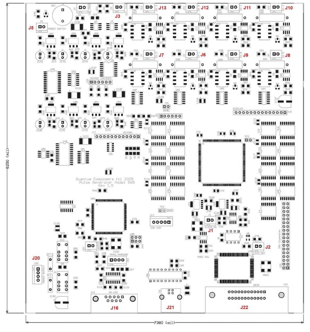
70 Figure 2 Component/Connector layout 66
9530/8530 Series Pulse Generator Operating Manual
 9530/8530 Series Pulse Generator Operating Manual QUANTUM COMPOSERS, INC PO Box 4248 Bozeman, MT 59772 (406)582-0227 phone (406)582-0237 fax www.quantumcomposers.com Rev 4.9 Contents 1. INTRODUCTION...
9520 Series Pulse Generator Operating Manual
 9520 Series Pulse Generator Operating Manual Version 5.6 Quantum Composers, Inc. 212 Discovery Drive Bozeman, MT 59718 Phone: (406)582-0227 Fax: (406)582-0237 www.quantumcomposers.com Your distributor:
BNC. 588 Series Pulse Generator Operating Manual
 BNC 588 Series Pulse Generator Operating Manual Berkeley Nucleonics Corp. 2955 Kerner Blvd. San Rafael, CA 94901 (415) 453-9955 phone (415) 453-9956 fax www.berkeleynucleonics.com rev 4.0 Contents 1 Introduction...
9520 Series Pulse Generator Operating Manual
 9520 Series Pulse Generator Operating Manual QUANTUM COMPOSERS, INC PO Box 4248 Bozeman, MT 59772 (406)582-0227 phone (406)582-0237 fax www.quantumcomposers.com July 2007 Bootrom: 1.02 FW: 1.20 This
505 Pulse Generator Operating Manual
 505 Pulse Generator Operating Manual Berkeley Nucleonics Corporation 2955 Kerner Blvd. San Rafael, CA 94901-5418 (415)453-9955 phone (415)453-9956 fax www.berkeleynucleonics.com May 2005 Contents 1 Introduction...
9730 Series Pulse Generator Operating Manual
 9730 Series Pulse Generator Operating Manual Version 1.4 Quantum Composers, INC 212 Discovery Drive Bozeman, MT 59718 Phone: (406)582-0227 Fax: (406)582-0237 www.quantumcomposers.com 1 Table of Contents
Operating Manual Version 1.10
 Operating Manual Version 1.10 Model 577 Pulse Generator Berkeley Nucleonics Corporation 2955 Kerner Blvd. San Rafael, CA 94901 Phone: 415-453-9955 Fax: 415-453-9956 Email: info@berkeleynucleonics.com Web:
HP 33120A Function Generator / Arbitrary Waveform Generator
 Note: Unless otherwise indicated, this manual applies to all Serial Numbers. The HP 33120A is a high-performance 15 MHz synthesized function generator with built-in arbitrary waveform capability. Its combination
Agilent 33210A 10 MHz Function / Arbitrary Waveform Generator. User s Guide
 User s Guide Publication Number 33210-90001 (order as 33210-90000 manual set) Edition 1, August 2008 Copyright 2008 Agilent Technologies, Inc. Agilent 33210A 10 MHz Function / Arbitrary Waveform Generator
Agilent 33220A. 20 MHz Waveform Generator. User's Guide. Agilent Technologies
 Agilent 33220A 20 MHz Waveform Generator User's Guide Agilent Technologies User s Guide Publication Number 33220-90002 (order as 33220-90100 manual set) Edition 4, May 2007 Copyright 2003, 2005, 2007 Agilent
Agilent 33250A 80 MHz Function / Arbitrary Waveform Generator. User s Guide
 User s Guide Publication Number 33250-90002 (order as 33250-90100 manual set) Edition 2, March 2003 Copyright Agilent Technologies, Inc. 2000, 2003 For Safety information, Warranties, and Regulatory information,
20 CHANNELS DIGITAL DELAY GENERATOR
 NUT 063 Ed. 2.2 September 2015 User's Manual MODEL 745-20C 20 CHANNELS DIGITAL DELAY GENERATOR 20 independent delay channels 100 ps delay resolution (1 ps option) 10 seconds delay range Adjustable output
DG645 Digital Delay Generator
 User Manual DG645 Digital Delay Generator Revision 1.0 (6/12/08) Certification Stanford Research Systems certifies that this product met its published specifications at the time of shipment. Warranty This
APPLICATION BULLETIN. SERIAL BACKGROUNDER (Serial 101) AB23-1. ICS ICS ELECTRONICS division of Systems West Inc. INTRODUCTION CHAPTER 2 - DATA FORMAT
 AB23-1. ICS ICS ELECTRONICS division of Systems West Inc. INTRODUCTION CHAPTER 2 - DATA FORMAT") ICS ICS ELECTRONICS division of Systems West Inc. AB- APPLICATION BULLETIN SERIAL BACKGROUNDER (Serial 0) INTRODUCTION Serial data communication is the most common means of transmitting data from one point
ICS ICS ELECTRONICS division of Systems West Inc. AB- APPLICATION BULLETIN SERIAL BACKGROUNDER (Serial 0) INTRODUCTION Serial data communication is the most common means of transmitting data from one point
PCX-7401 Pulsed Current Source Operation Manual
 Directed Energy, Inc. 1609 Oakridge Dr., Suite 100, Fort Collins, CO 80525 (970) 493-1901 sales@ixyscolorado.com ixyscolorado.com PCX-7401 Pulsed Current Source Operation Manual Contents Contents... 3
Select datum Page backward in. parameter list
 HEIDENHAIN Working with the measured value display unit ND Actual value and input display (7-segment LED, 9 decades and sign) Select datum Page backward in parameter list Confirm entry value Set display
GM8036 Laser Sweep Optical Spectrum Analyzer. Programming Guide
 GM8036 Laser Sweep Optical Spectrum Analyzer Programming Guide Notices This document contains UC INSTRUMENTS CORP. proprietary information that is protected by copyright. All rights are reserved. This
Mate Serial Communications Guide This guide is only relevant to Mate Code Revs. of 4.00 and greater
 Mate Serial Communications Guide This guide is only relevant to Mate Code Revs. of 4.00 and greater For additional information contact matedev@outbackpower.com Page 1 of 20 Revision History Revision 2.0:
ICS REPEATER CONTROLLERS
 ICS REPEATER CONTROLLERS BASIC CONTROLLER USER MANUAL INTEGRATED CONTROL SYSTEMS 1076 North Juniper St. Coquille, OR 97423 Email support@ics-ctrl.com Website www.ics-ctrl.com Last updated 5/07/15 Basic
Berkeley Nucleonics Corp. Model 625 Quick Start Guide
 Berkeley Nucleonics Corp. Model 625 Quick Start Guide 1. Apply power to the 625. After a display of the hardware and software versions and serial number, the unit enters the Basic Sinewave mode of operation.
LC-10 Chipless TagReader v 2.0 August 2006
 LC-10 Chipless TagReader v 2.0 August 2006 The LC-10 is a portable instrument that connects to the USB port of any computer. The LC-10 operates in the frequency range of 1-50 MHz, and is designed to detect
DSTS-5A/2C User's Manual
 ELECTRONIC DEVICES INC. P.O. BOX 15037, CHESAPEAKE, VA 23328. PH 757-421-2968 FAX 421-0518 DSTS-5A/2C User's Manual 1. PACKING LIST 2. OVERVIEW 3. CONNECTING THE DSTS-5A/2C TO A COMPUTER 4. CONNECTING
USB Multifunction Arbitrary Waveform Generator AWG2300. User Guide
 USB Multifunction Arbitrary Waveform Generator AWG2300 User Guide Contents Safety information... 3 About this guide... 4 AWG2300 specifications... 5 Chapter 1. Product introduction 1 1. Package contents......
SonoLab Echo-I User Manual
 SonoLab Echo-I User Manual Overview: SonoLab Echo-I is a single board digital ultrasound pulse-echo solution. The system has a built in 50 volt high voltage generation circuit, a bipolar pulser, a transmit/receive
CW Transmitter. User s Manual
 CW Transmitter User s Manual Warranty Statement PRAXSYM warrants that all items will be free from defects in material and workmanship under use as specified in this guide for a period of one year from
EE 314 Spring 2003 Microprocessor Systems
 EE 314 Spring 2003 Microprocessor Systems Laboratory Project #9 Closed Loop Control Overview and Introduction This project will bring together several pieces of software and draw on knowledge gained in
SDI SPECTRADYNAMICS, INC GHZ RUBIDIUM FREQUENCY SYNTHESIZER OPERATING MANUAL
 SPECTRADYNAMICS, INC. 6.834 GHZ RUBIDIUM FREQUENCY SYNTHESIZER RB-1 OPERATING MANUAL SPECTRADYNAMICS, INC 1849 Cherry St. Unit 2 Louisville, CO 80027 Phone: (303) 665-1852 Fax: (303) 604-6088 www.spectradynamics.com
Power Meter. Measurement Guide. for Anritsu RF and Microwave Handheld Instruments BTS Master Site Master Spectrum Master Cell Master
 Measurement Guide Power Meter for Anritsu RF and Microwave Handheld Instruments BTS Master Site Master Spectrum Master Cell Master Power Meter Option 29 High Accuracy Power Meter Option 19 Inline Peak
Confirm entry value Set display to value from Actual value and input display Select datum P79 (P80!) (7-segment LED,
 (7-segment LED,") HEIDENHAIN Working with the measured value display unit ND 261 Confirm entry value Set display to value from Actual value and input display Select datum P79 (P80!) (7-segment LED, Page backward in 9 decades
HEIDENHAIN Working with the measured value display unit ND 261 Confirm entry value Set display to value from Actual value and input display Select datum P79 (P80!) (7-segment LED, Page backward in 9 decades
G3P-R232. User Manual. Release. 2.06
 G3P-R232 User Manual Release. 2.06 1 INDEX 1. RELEASE HISTORY... 3 1.1. Release 1.01... 3 1.2. Release 2.01... 3 1.3. Release 2.02... 3 1.4. Release 2.03... 3 1.5. Release 2.04... 3 1.6. Release 2.05...
TECHNICAL MANUAL UNIVERSAL BOP GPIB VISA INSTRUMENT DRIVER. 1) This manual is valid for the following Model and associated serial numbers:
 This manual is valid for the following Model and associated serial numbers:") TECHNICAL MANUAL UNIVERSAL BOP GPIB VISA INSTRUMENT DRIVER KEPCO INC. An ISO 9001 Company. MODEL UNIVERSAL BOP GPIB VISA INSTRUMENT DRIVER ORDER NO. REV. NO. IMPORTANT NOTES: 1) This manual is valid for
TECHNICAL MANUAL UNIVERSAL BOP GPIB VISA INSTRUMENT DRIVER KEPCO INC. An ISO 9001 Company. MODEL UNIVERSAL BOP GPIB VISA INSTRUMENT DRIVER ORDER NO. REV. NO. IMPORTANT NOTES: 1) This manual is valid for
Metaphase ULC-2. Technologies ULC. Metaphase. Technologies Version 6.2 June 12, 2013 USER MANUAL. metaphase-tech.com. pg. 1
 ULC Version 6.2 June 12, 2013 USER MANUAL pg. 1 Overview Universal LED Controller () provides independent true constant-current or voltage control of two LED loads from 0.02 to 4 Amps continuous (DC) with
WARRANTY. Long Range Systems, LLC, 20 Canal St, Suite 4N, Franklin, NH 03235
 WARRANTY Long Range Systems, Inc. warrants the trap release product against any defects that are due to faulty material or workmanship for a one-year period after the original date of consumer purchase.
USER'S MANUAL. Model : K
 USER'S MANUAL Model : 2000-64K TM GINA MODEL 2000-64K Overview GINA Model 2000-64K is a stand-alone, high frequency data transceiver using spread spectrum technology. GINA 2000-64K capabilities include
INSTRUCTION MANUAL MODEL 4010A. 2 MHz FUNCTION GENERATOR MANUAL DE INSTRUCCIONES MODELO 4010A. 2MHz GENERADOR DE FUNCIONES
 INSTRUCTION MANUAL MANUAL DE INSTRUCCIONES MODEL 4010A MODELO 4010A 2 MHz FUNCTION GENERATOR 2MHz GENERADOR DE FUNCIONES TEST INSTRUMENT SAFETY WARNING Normal use of test equipment exposes you to a certain
Product Specification for model TT Transducer Tester Rev. B
 TT Rev B April 20, 2010 Product Specification for model TT Transducer Tester Rev. B The Rapid Controls model TT Rev B transducer tester connects to multiple types of transducers and displays position and
Select datum Page backward in parameter list
 HEIDENHAIN Working with the measured value display unit ND Actual value and input display (7-segment LED, 9 decades and sign) Select datum Page backward in parameter list Confirm entry value Set display
User Manual Solenoid Controller BI-SC1001
 User Manual Solenoid Controller BI-SC1001 NOTICE Brandstrom Instruments, 2017 85 Ethan Allen Highway Ridgefield, CT 06877 (203) 544-9341 www.brandstrominstruments.com No part of this document may be photocopied,
Arbitrary Function Generator
 Model: 4045B Arbitrary Function Generator USER MANUAL 2 Safety Summary The following safety precautions apply to both operating and maintenance personnel and must be observed during all phases of operation,
Metaphase ULC-2. Technologies ULC. Metaphase. Technologies Version 7.X August 2015 USER MANUAL. metaphase-tech.com. pg. 1
 ULC Version 7.X August 2015 USER MANUAL pg. 1 Overview Universal LED Controller () provides independent true constant-current or voltage control of two LED loads from 0.02 to 4 Amps continuous (DC) with
Gentec-EO USA. T-RAD-USB Users Manual. T-Rad-USB Operating Instructions /15/2010 Page 1 of 24
 Gentec-EO USA T-RAD-USB Users Manual Gentec-EO USA 5825 Jean Road Center Lake Oswego, Oregon, 97035 503-697-1870 voice 503-697-0633 fax 121-201795 11/15/2010 Page 1 of 24 System Overview Welcome to the
RF Wireless Serial Device Server
 RF-SDS RF Wireless Serial Device Server The RF-SDS subassembly is a radio transceiver acting as a Serial Device Server, which externally connects a remote serial RF transceiver to an Ethernet network (TCP/IP).
Harris IRT Enterprises Multi-Channel Digital Resistance Tester Model XR
 Harris IRT Enterprises Multi-Channel Digital Resistance Tester Model 6012-06XR Specifications & Dimensions 2 Theory of Operation 3 System Block Diagram 4 Operator Controls & Connectors 5 Test Connections
Arbitrary/Function Waveform Generators 4075B Series
 Data Sheet Arbitrary/Function Waveform Generators Point-by-Point Signal Integrity The Arbitrary/Function Waveform Generators are versatile high-performance single- and dual-channel arbitrary waveform generators
P G A Digital Stimulator Instruction Manual
 P G 4 0 0 0 A Digital Stimulator Instruction Manual 2005 Cygnus Technology, Inc. Technology, Inc. P.O.Box 219 Delaware Water Gap, PA 18327 Tel: (570) 424-5701 Fax: (570) 424-5630 Email: sales@cygnustech.com
Chapter 15: Serial Controlled (HF) Radio Support
 Radio Support") 15-1 Chapter 15: Serial Controlled (HF) Radio Support This section describes the controller's interface for serial controlled radios. Most such radios are for the HF bands, but some such as the FT-736
15-1 Chapter 15: Serial Controlled (HF) Radio Support This section describes the controller's interface for serial controlled radios. Most such radios are for the HF bands, but some such as the FT-736
INSTRUMENTS, INC. Models 2960AR and 2965AR Disciplined Rubidium Frequency Standards. Section Page Contents
 INSTRUMENTS, INC. Models 2960AR and 2965AR Disciplined Rubidium Frequency Standards 2960AR 2965AR Section Page Contents 1.0............................. 2......................... Description 2.0.............................
Property of Ramsey Electronics, Inc. Do not reproduce or distribute.
 USER GUIDE JANUARY, 2005 Rev. 1.3 SG560 SIGNAL GENERATOR Copyright Ramsey Electronics, Inc. 2005, All rights reserved 1 TABLE OF CONTENTS Introduction Opening the Box...4 Quick Start...4 Introduction...5
USING RS-232 to RS-485 CONVERTERS (With RS-232, RS-422 and RS-485 devices)
") ICS DataCom Application Note USING RS- to RS- CONVERTERS (With RS-, RS- and RS- devices) INTRODUCTION Table RS-/RS- Logic Levels This application note provides information about using ICSDataCom's RS-
ICS DataCom Application Note USING RS- to RS- CONVERTERS (With RS-, RS- and RS- devices) INTRODUCTION Table RS-/RS- Logic Levels This application note provides information about using ICSDataCom's RS-
Henry Dudley 1508 Wellington Ave. Toms River, NJ
 Henry Dudley 1508 Wellington Ave. Toms River, NJ 08757 732-240-6895 hdudley@dudleylab.com OM000001 REV01 RELEASE DATE 1/27/04 TABLE OF CONTENTS TABLE OF CONTENTS... 2 1.0 GENERAL INFORMATION... 3 1.1 Scope
WTDIN-M. eeder. Digital Input Module. Technologies FEATURES SPECIFICATIONS DESCRIPTION. Weeder Technologies
 eeder Technologies 90-A Beal Pkwy NW, Fort Walton Beach, FL 32548 www.weedtech.com 850-863-5723 Digital Input Module FEATURES 8 wide-range digital input channels with high voltage transient protection.
SDI SPECTRADYNAMICS, INC. LOW NOISE FREQUENCY SYNTHESIZER LNFS-400 OPERATING MANUAL
 SPECTRADYNAMICS, INC. LOW NOISE FREQUENCY SYNTHESIZER LNFS-400 OPERATING MANUAL SPECTRADYNAMICS, INC 1849 Cherry St. Unit 2 Louisville, CO 80027 Phone: (303) 665-1852 Fax: (303) 604-6088 www.spectradynamics.com
9200 Series, 300 MHz Programmable Pulse Generator
 9200 Series, 300 MHz Programmable Pulse Generator Main Features Variable edge pulses (1 nsec to 1 msec) at rates to 250 MHz Fast 300 psec edges to 300 MHz Wide output swings to 32 V at pulse rates to 50
Dual Channel Function/Arbitrary Waveform Generators 4050 Series
 Data Sheet Dual Channel Function/Arbitrary Waveform Generators The Dual Channel Function/Arbitrary Waveform Generators are capable of generating stable and precise sine, square, triangle, pulse, and arbitrary
5008 Dual Synthesizer Configuration Manager User s Guide (admin Version) Version valontechnology.com
 Version valontechnology.com") 5008 Dual Synthesizer Configuration Manager User s Guide (admin Version) Version 1.6.1 valontechnology.com 5008 Dual Synthesizer Module Configuration Manager Program Version 1.6.1 Page 2 Table of Contents
5008 Dual Synthesizer Configuration Manager User s Guide (admin Version) Version 1.6.1 valontechnology.com 5008 Dual Synthesizer Module Configuration Manager Program Version 1.6.1 Page 2 Table of Contents
Understanding the Arduino to LabVIEW Interface
 E-122 Design II Understanding the Arduino to LabVIEW Interface Overview The Arduino microcontroller introduced in Design I will be used as a LabVIEW data acquisition (DAQ) device/controller for Experiments
User manual. Inclinometer with Analog-RS232-Interface IK360
 User manual Inclinometer with Analog-RS232-Interface IK360 Table of content 1 GENERAL SAFETY ADVICE... 3 2 INTRODUCTION... 4 2.1 IK360... 4 2.2 ANALOG INTERFACE... 4 2.3 IK360 ANALOG... 4 3 INSTALLATION...
EVDP610 IXDP610 Digital PWM Controller IC Evaluation Board
 IXDP610 Digital PWM Controller IC Evaluation Board General Description The IXDP610 Digital Pulse Width Modulator (DPWM) is a programmable CMOS LSI device, which accepts digital pulse width data from a
WTDOT-M. eeder. Digital Output Module. Technologies FEATURES SPECIFICATIONS DESCRIPTION. Weeder Technologies
 eeder Technologies 90-A Beal Pkwy NW, Fort Walton Beach, FL 32548 www.weedtech.com 850-863-5723 Digital Output Module FEATURES 8 high-current open-collector output channels with automatic overload shutdown.
Function Generator Guide Tektronix AFG3102
 Tektronix AFG3102 ersion 2008-Jan-1 Dept. of Electrical & Computer Engineering Portland State University Copyright 2008 Portland State University 1 Basic Information This guide provides basic instructions
Model BPG-1P Biphasic Pulse Generator
 MicroProbes for Life Science Model BPG-1P Biphasic Pulse Generator Owner Manual Version: January, 2018 18247-D Flower Hill Way Gaithersburg, MD 20879 Phone: +1 301 330-9788 Fax: +1 301 330-9667 w w w.microprobes.com
Key Reference. Agilent Technologies E8257D/67D PSG Signal Generators. Manufacturing Part Number: E Printed in USA July 2007
 Agilent Technologies E8257D/67D PSG Signal Generators This guide applies to the following signal generator models: E8267D PSG Vector Signal Generator E8257D PSG Analog Signal Generator Due to our continuing
GFT1012 2/4 Channel Precise Slave Generator
 Features Two Independent Delay Channels (Four channels available as an option) 1 ps Time Resolution < 5 ps RMS Jitter (Slave-to-Slave) < 6 ps / C Drift (Slave-to-slave) 1 Second Range Output Pulse Up to
Agilent 3499A/B/C Switch/Control system
 User s Guide Copyright Agilent Technologies, Inc. 2000, 2002 For Safety information, Warranties, and Regulatory information, see the pages following the Index. Agilent 399A/B/C Switch/Control system Agilent
Line-to-line RMS Volts, 3 phases 4 digits (XXX.X) Volts
 Volts") digital ac POWER MONITOR DESCRIPTION The DSP is a three-phase, three-element multifunction digital transducer with outputs for voltage, current, and power via serial communication. Applications include
digital ac POWER MONITOR DESCRIPTION The DSP is a three-phase, three-element multifunction digital transducer with outputs for voltage, current, and power via serial communication. Applications include
Model 305 Synchronous Countdown System
 Model 305 Synchronous Countdown System Introduction: The Model 305 pre-settable countdown electronics is a high-speed synchronous divider that generates an electronic trigger pulse, locked in time with
LincView OPC USER GUIDE. Enhanced Diagnostics Utility INDUSTRIAL DATA COMMUNICATIONS
 USER GUIDE INDUSTRIAL DATA COMMUNICATIONS LincView OPC Enhanced Diagnostics Utility It is essential that all instructions contained in the User Guide are followed precisely to ensure proper operation of
I-7088, I-7088D, M-7088 and M-7088D User Manual
 I-7088, I-7088D, M-7088 and M-7088D User Manual I-7000 New Features 1. Internal Self Tuner 2. Multiple Baud Rates 3. Multiple Data Formats 4. Internal Dual WatchDog 5. True Distributed Control 6. High
3100LA Broadband Power Amplifier
 3100LA Broadband Power Amplifier HIGH RF VOLTAGES MAY BE PRESENT AT THE OUTPUT OF THIS UNIT. All operating personnel should use extreme caution in handling these voltages and be thoroughly familiar with
LV-Link 3.0 Software Interface for LabVIEW
 LV-Link 3.0 Software Interface for LabVIEW LV-Link Software Interface for LabVIEW LV-Link is a library of VIs (Virtual Instruments) that enable LabVIEW programmers to access the data acquisition features
µchameleon 2 User s Manual
 µchameleon 2 Firmware Rev 4.0 Copyright 2006-2011 Starting Point Systems. - Page 1 - firmware rev 4.0 1. General overview...4 1.1. Features summary... 4 1.2. USB CDC communication drivers... 4 1.3. Command
Internal Ethernet and RS-232 Interface for XFR Series Programmable DC Power Supplies. Operating Manual ENET-XFR ENET-XFR3
 TM-XR9B-01XN.book Page i Tuesday, February 3, 2004 10:13 AM ENET-XFR ENET-XFR3 Operating Manual Internal Ethernet and RS-232 Interface for XFR Series Programmable DC Power Supplies TM-XR9B-01XN.book Page
IVI STEP TYPES. Contents
 IVI STEP TYPES Contents This document describes the set of IVI step types that TestStand provides. First, the document discusses how to use the IVI step types and how to edit IVI steps. Next, the document
UART2PPM. User s Guide. Version 2.04 dated 02/20/16. Gregor Schlechtriem
 UART2PPM User s Guide Version 2.04 dated 02/20/16 Gregor Schlechtriem www.pikoder.com UART2PPM User s Guide Content Overview 3 PCC PiKoder Control Center 5 Getting started... 5 Real-time Control... 7 minissc
HP 16533A 1-GSa/s and HP 16534A 2-GSa/s Digitizing Oscilloscope
 User s Reference Publication Number 16534-97009 February 1999 For Safety Information, Warranties, and Regulatory Information, see the pages behind the Index Copyright Hewlett-Packard Company 1991 1999
DigiSpeed-SL DC-04. Isolated Control Voltage Generator User s Guide. DigiSpeed PCB Ver:1.0 Firmware Ver: 1.0 Mach3 Ver: Updated: 5.
 DigiSpeed-SL - Users Guide Page 1 Updated: 5. June 2008 DigiSpeed-SL DC-04 Isolated Control Voltage Generator User s Guide DigiSpeed PCB Ver:1.0 Firmware Ver: 1.0 Mach3 Ver: 1.84 DigiSpeed-SL - Users Guide
Instruction Manual ABM HART Gateway Software. Instruction Manual Revision A.1
 Instruction Manual ABM HART Gateway Software Instruction Manual Revision A.1 Table of Contents Section 1: Getting Started... 3 1.1 Setup Procedure... 3 1.2 Quick Setup Guide for Ultrasonic Sensors... 11
PROGRAMMABLE INTRACRANIAL SELF- STIMULATION (ICSS) CURRENT STIMULATOR
 CURRENT STIMULATOR") instrumentation and software for research PROGRAMMABLE INTRACRANIAL SELF- STIMULATION (ICSS) CURRENT STIMULATOR PHM-15X USER S MANUAL DOC-012 Rev. 1.8 Copyright 2012 All Rights Reserved Med Associates
instrumentation and software for research PROGRAMMABLE INTRACRANIAL SELF- STIMULATION (ICSS) CURRENT STIMULATOR PHM-15X USER S MANUAL DOC-012 Rev. 1.8 Copyright 2012 All Rights Reserved Med Associates
Operator Manual 1.4 FRACSIM MINI
 FracSim Meters FracSim Meters was founded with the intention of providing specifically designed tools for the well service industry. Our goal is to provide quality tools with a robust design to meet the
XDC 6000 Watt and Watt Series Digital Programmable DC Power Supply. Operating Manual
 XDC 10-600 XDC 20-300 XDC 30-200 XDC 40-150 XDC 60-100 XDC 80-75 XDC 100-60 XDC 150-40 XDC 300-20 XDC 600-10 XDC 10-1200 XDC 20-600 XDC 30-400 XDC 40-300 XDC 60-200 XDC 80-150 XDC 100-120 XDC 150-80 XDC
GFT1504 4/8/10 channel Delay Generator
 Features 4 independent Delay Channels (10 in option) 100 ps resolution (1ps in option) 25 ps RMS jitter (channel to channel) 10 second range Channel Output pulse 6 V/50 Ω, 3 ns rise time Independent control
Copley ASCII Interface Programmer s Guide
 Copley ASCII Interface Programmer s Guide PN/95-00404-000 Revision 4 June 2008 Copley ASCII Interface Programmer s Guide TABLE OF CONTENTS About This Manual... 5 Overview and Scope... 5 Related Documentation...
Robotic Manipulation Lab 1: Getting Acquainted with the Denso Robot Arms Fall 2010
 15-384 Robotic Manipulation Lab 1: Getting Acquainted with the Denso Robot Arms Fall 2010 due September 23 2010 1 Introduction This lab will introduce you to the Denso robot. You must write up answers
Dragon. manual version 1.7
 Dragon manual version 1.7 Contents DRAGON TOP PANEL... 2 DRAGON STARTUP... 2 DRAGON STARTUP SCREEN... 2 DRAGON INFO SCREEN... 3 DRAGON MAIN SCREEN... 3 TURNING ON A TRANSMITTER... 4 CHANGING MAIN SCREEN
INSTRUCTION MANUAL IP REMOTE CONTROL SOFTWARE RS-BA1
 INSTRUCTION MANUAL IP REMOTE CONTROL SOFTWARE RS-BA FOREWORD Thank you for purchasing the RS-BA. The RS-BA is designed to remotely control an Icom radio through a network. This instruction manual contains
HURRICANE Radio Modem. FULL DUPLEX Radio MODEM
 FULL DUPLEX Radio MODEM Direct Cable Replacement Range 2KM RS232 / RS485 / USB Host Data Rates up to 38,400 Baud RF Data Rates to 115200Kbps Waterproof IP68 Enclosure 8 User Selectable Channels CE Compliant
2100L Broadband Power Amplifier
 2100L Broadband Power Amplifier HIGH RF VOLTAGES MAY BE PRESENT AT THE OUTPUT OF THIS UNIT. All operating personnel should use extreme caution in handling these voltages and be thoroughly familiar with
MICROWAVE FREQUENCY SYNTHESIZER QP-FSPLL USER MANUAL
 MICROWAVE FREQUENCY SYNTHESIZER QP-FSPLL-0040-01 USER MANUAL The QP-FSPLL-0040-01 is a low-phase noise wideband synthesizer operating from 50 MHz to 40 GHz with a nominal output power of +15 dbm. The synthesizer
RIGOL. Quick Guide. DG2000 Series Function/Arbitrary Waveform Generator. Sept RIGOL Technologies, Inc.
 Quick Guide DG2000 Series Function/Arbitrary Waveform Generator Sept. 2010 RIGOL Technologies, Inc. Guaranty and Declaration Copyright 2010 RIGOL Technologies, Inc. All Rights Reserved. Trademark Information
5700A/5720A Series II Multi-Function Calibrator
 5700A/5720A Series II Multi-Function Calibrator Operator Guide PN 601648 May 1996 1996 Fluke Corporation, Inc. All rights reserved. Printed in U.S.A. Contents What is in this Guide?... 2 Safety Summary...
5700A/5720A. Operator Guide. Series II Multi-Function Calibrator
 5700A/5720A Series II Multi-Function Calibrator Operator Guide PN 3474006 May 1996, Rev. 1, 5/09 2009 Fluke Corporation. All rights reserved. Printed in USA. All product names are trademarks of their respective
BAND AIDE AUTOMATIC BAND DECODER
 BAND AIDE AUTOMATIC BAND DECODER 1. Features Overview The Top Ten Devices Band Aide is an accessory that attaches to your radio (or computer), decodes the band data provided by the radio, and provides
LAB II. INTRODUCTION TO LABVIEW
 1. OBJECTIVE LAB II. INTRODUCTION TO LABVIEW In this lab, you are to gain a basic understanding of how LabView operates the lab equipment remotely. 2. OVERVIEW In the procedure of this lab, you will build
MS2711B Hand-Held Spectrum Analyzer
 MS2711B Hand-Held Spectrum Analyzer Programming Manual Hand-Held Spectrum Analyzer, for Measuring, Monitoring and Analyzing Signal Environments WARRANTY The Anritsu product(s) listed on the title page
WIRES-X Portable Digital Node Function. Instruction Manual
 Wide-Coverage Internet Repeater Enhancement System WIRES-X Portable Digital Node Function Instruction Manual Please read this Instruction Manual carefully for appropriate procedure. Preparation Procedure
BeeLine TX User s Guide V1.1c 4/25/2005
 BeeLine TX User s Guide V1.1c 4/25/2005 1 Important Battery Information The BeeLine Transmitter is designed to operate off of a single cell lithium polymer battery. Other battery sources may be used, but
3 GHz Carrier Backhaul Radio. Model: AF-3X. Tel: +44 (0) Fax: +44 (0) LINK GPS MGMT DATA DATA
 Fax: +44 (0) LINK GPS MGMT DATA DATA") LINK GPS MGMT DATA DATA MGMT GPS LINK 3 GHz Carrier Backhaul Radio Model: AF-3X LINK GPS MGMT DATA 3 GHz Carrier Backhaul Radio Model: AF-3X LINK GPS MGMT DATA DATA MGMT GPS LINK Introduction Thank you
LINK GPS MGMT DATA DATA MGMT GPS LINK 3 GHz Carrier Backhaul Radio Model: AF-3X LINK GPS MGMT DATA 3 GHz Carrier Backhaul Radio Model: AF-3X LINK GPS MGMT DATA DATA MGMT GPS LINK Introduction Thank you
PI-10 Broadband Power Indicator
 PI-10 Broadband Power Indicator HIGH RF VOLTAGES MAY BE PRESENT AT THE PORTS OF THIS UNIT. All operating personnel should use extreme caution in handling these voltages and be thoroughly familiar with
LinkAlign-60RPT Set-up and Operation Manual
 LinkAlign-60RPT Set-up and Operation Manual LinkAlign Setup and Operation Proprietary, Nextmove Technologies Page 1 LinkAlign Setup and Operation Proprietary, Nextmove Technologies Page 2 Description of
HOMANN DESIGNS. DigiSpeed. Instruction manual. Version 1.0. Copyright 2004 Homann Designs.
 HOMANN DESIGNS DigiSpeed Instruction manual Version 1.0 Copyright 2004 Homann Designs http://www.homanndesigns.com Table of Contents Introduction...3 Features...3 DigiSpeed Operation Description...5 Overview...5