SVR-D300 DMR. VHF MHz UHF-A MHz UHF-D MHz. Models SVR-D300V, SVR-D300UA, SVR-D300UD SVR-D300
|
|
|
- Elwin Ross Matthews
- 5 years ago
- Views:
Transcription


1 SVR-D300 DMR Models SVR-D300V, SVR-D300UA, SVR-D300UD VHF MHz UHF-A MHz UHF-D MHz SVR-D300
2 Table of Contents Foreword... 3 Specifications... 4 Intellectual Property Rights... 4 Functional Description... 5 Multi-Vehicle Operation... 5 ESP Priority... 6 Local Mic Repeat... 6 Trunking Operation... 7 Emergency Operation... 7 WideBand/NarrowBand Channels... 7 Courtesy Beep... 7 Power Up Channel... 7 LED Indicators... 8 Installation... 9 Jumpers... 9 Main Connector... 9 Alignment Programming Common Data Channel Data Transfer Menu Remote Help Flash Programming Parts Locator Main PCB Page 2
3 Foreword Scope of This Manual This manual contains the specifications, functional description, operating instructions, schematic, parts locator and parts list for the SVR-D300 synthesized vehicular repeater. This manual is intended for use by qualified service technicians to aid them with installation, interfacing, alignment and trouble shooting of the SVR-D300 when used with other land mobile radios. Service Manual Revisions Component changes, additions and deletions may occur in the circuit design to improve operation and will be reflected in future releases of this service manual. Specifications and circuit changes are subject to change without prior notice or obligation by Pyramid Communications. Safety Information The SVR-D300 is designed to operate within all applicable Federal regulations at the time of manufacture. Proper operation and service procedures will assure continued compliance with these regulations: Do not operate any SVR-D300 without an antenna or appropriate RF load connected to the antenna connector. Do not operate any SVR-D300 in the presence of unshielded electrical blasting caps or explosive environmental conditions. Do not operate any SVR-D300 while refueling the vehicle or in the presence of explosive fumes. Do not operate any SVR-D300 with persons standing closer than 2 feet from the mobile or repeater antenna. FCC Information The SVR-D300 complies with the FCC rules parts 90 and 22 for radio frequency transmitters. The user must apply for a license to operate the SVR-D300 transmitter pursuant to parts and Other FCC rules may apply depending on the class of service the user qualifies for. A complete listing of FCC rules and regulations may be ordered from: Superintendent of Documents Government printing office Washington DC The following information pertaining to the SVR-D300 should be included in the FCC license application: VHF UHF-A or UHF-D Type Acceptance: LRUSVR-D300V LRUSVR-D300U(A) or (D) Output Power: 1-2.0W 1-2.0W Frequency band: MHz or Mhz Number of Channels: Emission designators: 10K0F1D, 10K0F1E, 10K0F7D, 10K0F7E, 11K0F3E, 12K3F1D, 16K0F3E, 4K8F2D 7K6F1D, 8K1F1D, 8K1F1E, 8K1F7D, 8K1F7E, 8K4F2D Page 3
4 Specifications Transmitter: VHF UHF-A UHF-D Frequency Range: MHz MHz Rf power out: 1-2W 1-2W 1-2W Spurious emissions: -80dBc -80 dbc -80 dbc Freq stability -30 ~+60 C: 1.0 PPM 1.0 PPM 1.0 PPM Hum and Noise: 45dB 40dB 40dB Audio response (300-3kHz): Flat or +6dB/octave Flat or +6dB/octave Flat or +6dB/octave Audio distortion: 60% deviation 60% deviation 60% deviation Local mic sensitivity: 300mV-5VPP 300mV-5VPP 300mV-5VPP FCC Type Acceptance: LRUSVR-D300V LRUSVR-D300UA LRUSVR-D300UA Industry Canada Approval: 2390A-SVR300V 2390A-SVR300UA Not Approved in Canada Receiver: Frequency Range: MHz MHz RF sensitivity Analog:.28µV.28µV.28µV Digital (5% BER):.20µV.20µV.20µV Squelch sensitivity:.2µv to 2µV adjustable.2µv to 2µV adjustable.2µv to 2µV adjustable Selectivity: 81db 80dB 80dB Spurious/image rejection: 87db 85db 85db IMD response: 80db 75db 75db Frequency stability: 1.0 PPM 1.0 PPM 1.0 PPM Audio response (300-3kHz): Flat or -6db/octave Flat or -6db/octave Flat or -6db/octave Audio output: 0-5VPP AC coupled 0-5VPP AC coupled 0-5VPP AC coupled Local Rx Audio: 400 mw 8 Ohms 400 mw 8 Ohms 400 mw 8 Ohms Power Requirements: DC Supply 13.6 VDC 13.6VDC 13.6VDC Standby 350 ma 350 ma 350 ma Receive 400 ma 400 ma 400 ma Transmit 2W 2W 2W Physical: Dimensions: Weight: Case: 5.75"W x 8"L x 2.25"H 50 oz. One piece extruded aluminum Intellectual Property Rights DMR TM is a protocol name for the digital communications systems using 4-level FSK technology which has been developed by JVCKenwood and Icom. ESP TM is a protocol name for the multi-vehicle protocol used by Pyramid Communications SVR products has been developed by Pyramid Communications for use only in this product. The AMBE+2 TM voice coding Technology embodied in this product is protected by intellectual property rights including patent rights, copyrights and trade secrets of DVSI (Digital Voice Systems, Inc. This voice coding Technology is licensed solely for the use within this Communications Equipment. The user of this Technology is explicitly prohibited from attempting to extract, remove, decompile, reverse engineer, or disassemble the Object Code or in any other way convert the Object Code into a human-readable form. US Paten Nos. #5,870,405, #5,826,222,#5,754,974, #5,701,390, #5,715,365, #5,649,050, #5,630,011, #5,581,656, #5,517,511 and #5,491,772. Firmware Copyrights: The title to and ownership of copyrights for firmware embedded in this product and memories are reserved for Pyramid Communications and JVCKenwood respectively. Page 4
5 Functional Description Generally, vehicular repeaters are used as mobile extenders in cross-band operation: the link is VHF or UHFMHz simplex and the mobile is Lo-band, VHF, UHF conventional or trunking. In-band operation is possible, but care must be taken to prevent interference between the mobile's higher power transmitter and the repeater receiver. Proper frequency selection and antenna placement are important even in cross-band operation, but especially for inband use. Low power pre-selector & notch filter cavities may be placed in line with the repeater antenna cable since it is simplex and low power. Important Note Analog Operation The SVR-D300 is designed to operate on simplex frequencies; part of the multi-vehicle format dictates that all of the SVR D300s must be able to monitor all link traffic on site and be able to determine if a handheld is transmitting, or if other repeaters are transmitting. In Analog mode, the handhelds must transmit CTCSS, but should be carrier squelch receive. The handhelds do not use CTCSS decode if the repeater is utilizing the multi vehicle format, as this will interfere with the priority sampling which is essential for multi-vehicle operation. Also, the handhelds would have to have different encode and decode tones in order for the repeater to be able to tell the difference between handhelds and other repeaters, so the handhelds would not be able to hear each other. The repeaters will not transmit CTCSS unless used only in a single vehicle environment. Important Note DMR Operation In DMR mode, the SVR-D300 must also operate on simplex frequencies in Tier 2 operation. The handhelds must transmit a different GID code than the SVR-D300 transmit GID code, and the Handheld MUST Transmit the GID and must bet set to decode several GIDs, incuding (All-Call), through The SVR uses different GID calls to signal intercommuncations. Decoding multiple GID's can be setup different ways depending on the model of portable radio. When the user leaves the vehicle, they activate the SVR-D300 via their mobile radio front panel or a separate switch. When the mobile radio is receiving carrier and proper tone, the SVR-D300 will begin transmitting on the handheld s receive frequency. The user is able to hear and respond to all radio traffic, including other handhelds at the site. In analog mode the SVR-D300 can be programmed to give the handhelds priority in a conversation by periodically sampling for handheld activity (carrier and proper tone) during base-to-portable transmissions. During sampling, if the SVR-D300 detects a handheld transmission, it will cease transmissions, key the mobile radio and repeat portable-to-base. This allows the handheld to respond during repeater hang time or during full duplex interconnect calls. Priority sampling can be enabled/disabled through PC programming and the interval can be programmed between.25 seconds and 2.5 seconds in.25 second increments. Priority sampling is not available in DMR mode. The SVR-D300 has a programmable time out timer for base-to-portable transmissions. If the mobile COR is active for more than the programmed time (and the SVR-D300 is the priority unit) it will send a double blip and cease transmission until the mobile COR is inactive. The time-out is in affect regardless of whether the SVR D300 is programmed for priority sampling or not. Multi-Vehicle Operation The SVR-D300 has 2 different multi-vehicle priority formats; both are compatible with the existing SVR- 200 and Motorola PAC/RT formats. The new SVR-D300 with ESP TM logic has enhanced features that ensures a priority vehicle is selected and ready to transmit during the idle time rather than during voice transmissions. The 2 formats are explained below: SVR-200 Legacy Format When the SVR-D300 is first activated, it will transmit a short lock tone that alerts the user that the system is functioning. It will then assume the priority status and be ready to repeat any base-to-portable or portable-tobase transmissions. If another unit arrives on scene and is activated, it too will transmit the lock tone ; when Page 5
6 the first SVR-D300 detects the lock tone from the second unit, it will increment a priority counter and will no longer repeat any transmissions. The recently arrived unit will be the priority repeater, and the first unit will be 1 count away from priority. This process will continue for each unit that arrives at the site, creating a priority hierarchy for up to 256 vehicles, each with a unique count and only one unit at priority status. The SVR-D300 will not transmit its lock tone if the radio channel is busy when first enabled. It will wait in non priority status until all transmissions cease, then send its lock tone and become the priority unit. Even though the other SVR-D300s are not at priority status, they will continue to monitor the channel for activity. If the priority unit were to leave the scene or become disabled, the other units will detect the condition to repeat and determine that there is no priority unit repeating the transmission. They will then begin to decrement their priority counters until one of them reaches the priority status and begins repeating the transmission. Since the SVR-D300s are all at different counts, only one will reach priority status and begin transmitting. The other units will sense the new priority repeater and cease counting down, preserving the priority hierarchy. If another unit were to arrive from a different scene and it is still the active priority, there will be two active repeaters on the air when a condition to repeat exists. When one of the SVR-D300s unkeys to check for handheld activity (analog mode only), it will detect the presence of the other active SVR-D300 and increment its priority counter and cease transmission. This is the self clearing mode to prevent radio collisions. ESP TM Priority The SVR-D300 Enhanced Sensor Priority works similar to the SVR-200 and PAC/RT formats and is completely backward compatible with those systems. The SVR-D300 determines if there is a priority (and re-establishes the priority if missing) during idle time between conversations rather than at the critical start of a conversation. When a condition to repeat exists, the SVR-D300 is always ready. The priority SVR-D300 will transmit a short tone burst every 10 seconds. This serves 2 purposes: It informs the handheld operator that they are still within range of the vehicle and it alerts the non-priority units that a priority vehicle is still on scene. As long as the non-priority units hear this "beacon" every 10 seconds, they preserve their counts and maintain the priority hierarchy. If the priority vehicle leaves the scene, after 10 seconds, the non-priority vehicles will not hear the "beacon" and begin counting down. When one of the counts=0, that SVR-D300 will send lock tone for 800 ms, assume priority and begin sending the "beacon" tone every 10 seconds as before. Since the "beacon" tone must be heard every 10 seconds, it does not have busy carrier lock out and will send the tone if 2 handhelds are communicating directly or in the presence of co-channel interference. Page 6
7 Emergency Operation (DMR mode Only) SVR-D300 Service Manual The SVR-D300 can be programmed for Emergency operation on a per channel basis. If enabled, the SVR-D300 can detect an Emergency Status in the DMR data packet. The emergency status will indicate an Emergency condition from the portable and will assert an output pin when decoded. There are 2 different Emergency formats: EMG output only or EMG output with voice repeat. EMG output only will assert pin 10 on the main cable for as long as the Emergency call is being received; it is used as a momentary output to the mobile to initiate an Emergency sequence. This is the common configuration with most radios. EMG output with voice repeat will assert pin 10 as before, but will also key the mobile and repeat portableto-base as long as the Emergency call is being received. This format is used with only some mobile radios that support an external emergency with PTT. Additionally, there is a solder jumper on the main logic PCB that determines if the EMG output signal pulls to ground (NO) or breaks ground (NC). Courtesy Beep If enabled, the SVR-D300 will send a short beep to the handheld user at the end of each portable-to-base transmission to confirm that the user is still within range. Power Up Channel The SVR-D300 can be programmed to revert to the last channel used when powered down or a pre-programmed "Home" Channel. Page 7

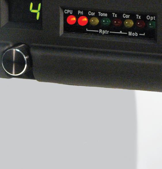
8 LEDs The SVR-D300 has a 2 digit channel display as well as eight status LEDs: CPU: PRI: RCOR: RTONE: RTX: MCOR: MTX: OPT: Flashes at a 1 Hz rate to indicate proper operation of the microprocessor. When on, indicates that the unit is at priority count zero and will repeat all transmissions. Repeater Carrier detect. Repeater sub-audible decode; when on, indicates a condition to repeat portable-to-base. Repeater transmit indicator. Mobile unmute detector indicating a condition to repeat base-to-portable. Mobile transmit indicator. Emergency Tone/Code Decode. If the 2 digit channel shows "- -", the unit is not enabled. Use the Blue Wire (pin 3) or the front control head switch to enable the SVR-D300. If the decimal point is illuminated in the 2 digit channel display it indicates a DMR channel is selected. Page 8
9 Installation Before installing the SVR-D300, ensure that the mobile radio is properly aligned per the manufacturer's tuning instructions. Additionally, ensure that the SVR-D300 jumpers are properly configured for use with the particular mobile radio that it will be connected to: J1 Controls the maximum drive level of the transmit audio output to the mobile radio. If J1 is installed, output amp U1A will have an adjustment range of mvpp. If J1 is removed, U1A can be adjusted between 0-5VPP. J2 Controls the output impedance of the transmit audio line to the mobile radio. If connected to a low impedance point in the mobile, installing JP2 sets the output impedance to 600 ohms. If JP2 is open, the output impedance is 2.2Kohms. Install the jumper for radios that require a lot of modulation drive or that have low impedance microphone circuits. Remove the jumper if the SVR-D300 installation decreases local microphone audio at the mobile. J4 Used to internally tie the local mic input of the SVR-D300 to the transmit audio output line which is usually connected to the mic hi line in the mobile. J5 Used to internally tie the on-air detect input of the SVR-D300 to the PTT output. Do so only on conventional radios; trunking radios must have the on-air detect line connected to a line indicating that the radio is transmitting. J6 Changes the maximum gain of the local mic input amp from unity (Out) to 10x (In). J7 Changes the maximum gain of the receive audio line input from unity (Out) to 7x (In). J8 Adds a pull up (+ position) or pull down (- position) resistor to the remote enable line (blue). J9 Adds a pull up resistor (10K to 5VDC) to mobile COR line (violet) J10 Connects the front panel on-off control to the remote enable line to enable the SVR-D300 from the front panel. J11 Adds (Out) or removes (In) a 100KOhm resistor in series with the Tx audio line for applications with low level mic audio and alternator whine problems (see Service Bulletin 113). EMG Selects the Emergency output polarity: NO=pull to ground during Emg NC=break ground during Emg. Make the connections between the mobile radio and the SVR-D300 cable as follows: Pin 1: Black/Shield Pin 2: White Pin 3: Blue Ground. Connect to the radio's chassis or ground plane. Mobile transmit audio. Connect to the mobile transmit audio path or tone input. If connected to the mobile mic input, ensure that the SVR-D300 is programmed for flat (common data). If connected after pre-emphasis, ensure that the SVR-D300 transmit audio path is programmed for pre-emphasis. Pin 2 is AC coupled and has an output impedance of 600 or 2.2Kohms (determined by J2). RV3 sets the transmit audio output level and J1 sets the adjustment range between 0-5VPP (J1 open) or 0-100mVPP (J1 shorted). Remote enable/disable. Connect to the radio's auxiliary output or a separate switch to remotely enable or disable the repeater. If this line goes high to activate the repeater, ensure that JP1 is set to the + position. If this line goes to ground, set JP1 to the - position. J8 has two positions to add a pull up (+) or pull down (-) resistor to this line if used with an open collector or dry contact output. J10 connects this line to the front panel on/off control. Page 9
10 Pin 4: Green Pin 5: Red Pin 6: Yellow Pin 7: Violet Pin 8: Brown Pin 9: Gray Pin 10: Black/White Mobile PTT output. Connect to mic PTT on the mobile radio, or a line that goes active low to transmit. Pin 4 is an open drain output rated at 2A at 15VDC. 12 VDC input. Connect to the radios 12V switched supply or a point capable of supplying at least 2A of current. Mobile receive audio. Connect this line to the mobile receive audio path before the volume control. If pin 6 is connected to the mobile discriminator, ensure that the SVR-D300 receive path is programmed for de-emphasis (common data). If connected after de-emphasis, program the receive path for flat. Pin 6 is AC coupled and high impedance (>15K ohm). RV5 sets the receive audio level sensitivity; this input should be between 30mVPP and 5VPP. J7 sets the gain of the receive input amp. If open, the input has a maximum gain of one; if installed, the input has a maximum gain of 7. Mobile COR detect. This line is used to indicate when the SVR-D300 should repeat the transmission to the handheld. Connect to a logic point in the radio that indicates proper tone and carrier have been detected or the audio unmute line. If this line goes more positive during an unmute condition, program the mobile COR line as active high (common data). If the line goes more negative during an unmute condition, program the mobile COR line as active low. The input from pin 7 is high impedance and does not have to go rail to rail. The SVR-D300 uses a voltage comparator as a COR threshold detector and is factory set at 1.6VDC. The COR input must go at least 0.5VDC on either side of this threshold. Not used. On Air Detect. Trunking: Connect to a point in the radio that indicates the mobile transmitter is actually on the air. This is not the same as mic PTT. If pin 9 goes positive during transmit, program the on-air detect line for active high (common data). If pin 9 goes to ground during transmit, program the on air detect line for active low. Conventional: Used for local mic repeat indication from the mobile. Connect pin 9 to pin 4 of the SVR-D300 and program the on-air detect line for active low. Solder jumper J5 will connect pin 9 to pin 4 (PTT output) and can be used on conventional systems only. Do not install J5 for trunking operation. Emergency Output. Connect to the Emergency input on the mobile radio. On Motorola radios, the Emergency input opens from ground on activation and jumper J13 should be in the "NC" position. On all other radios, the Emergency input pulls to ground on activation and jumper J13 should be in the "NO" position. Install the SVR-D300 in the vehicle using the supplied mounting bracket and hardware. Install the unit where it will be easily visible by the driver and will not interfere with the drivers vision or constitute a hazard during a vehicle collision. The SVR-D300 mounts in the bracket using the four 8-32 x ¼" machine screws. Do not use longer screws to mount the SVR-D300 to the bracket or circuit damage may result. Page 10
11 Alignment Before aligning the SVR-D300, ensure that the mobile radio is aligned per the manufacturer s service procedure; Ensure that the SVR-D300 is properly programmed and the jumpers are set per the previous section. In order to properly align the SVR-D300, you will need two service monitors and the mobile radio that the repeater will be installed with. Dis-assemble the repeater by removing the two cap screws on the front panel; disconnect the front panel from the main chassis by removing the 2 connectors. Remove the two cap screws from the rear panel and slide the main circuit board out of the housing with the rear panel attached. Re-connect the front panel to the main PCB. Connect one service monitor to the SVR-D300 TNC jack and the other to the mobile antenna jack. Connect the cable from the mobile radio to the SVR-D300 (See figure 4 on page 11). Turn on the mobile and activate the SVR-D300. SVR-D300 Transmitter 1. Maximum deviation/lock tone deviation: Press S3 (Test) and adjust RV7 (Lock Tone) for maximum. Adjust RV8 (repeater deviation) until the wave form just enters clipping; adjust RV7 for total 60% deviation. Release S3. 2. Mobile COR: Measure the voltage at TP2 (R11) on the SVR-D300 main PCB and record. Ensure the mobile COR LED on the front panel is off. Set the mobile service monitor for the mobile receive frequency, 1mV RF output and CTCSS modulation of 15% deviation. Measure the voltage again at TP2 and record. Ensure the mobile COR LED on the front panel is on. The 2 voltages at TP2 must be at greater than 2.1VDC and less than 1.1 VDC. 3. RX audio sensitivity/ctcss deviation: Set the service monitor connected to the mobile for the mobile receive frequency and 1mV RF output. Modulate the signal generator with a 1kHz tone at 60% deviation and CTCSS tone at 15% deviation. Ensure that the SVR-D300 mobile COR and repeater PTT LED s are on. Adjust RV5 on the SVR-D300 main board for 75% deviation if CTCSS/DCS transmit is programmed, adjust for 60% deviation if carrier squelch transmit, as read on the service monitor connected to the SVR-D300. Turn the RF output from the mobile service monitor off and ensure that the SVR-D300 mobile COR and repeater PTT LEDs are off. Page 11


12 SVR-D300 Receiver 1. Transmit audio output: Adjust the service monitor RF output for 1mV. Turn the CTCSS modulation on and set for 15% deviation. Confirm that the repeater COR, CTCSS and mobile PTT LED s are on. Adjust RV3 on the SVR-D300 main board for 60% deviation as read on the service monitor connected to the mobile radio. Turn off the CTCSS modulation of the service monitor connected to the SVR-D300. Confirm that the repeater CTCSS and mobile PTT LED s are off. 2. Lock Tone/Code Decode: Change the 1kHz tone modulation to the lock tone frequency or proper LOCK/ RAN in DMR mode. Confirm that the PRI LED goes off after approximately.5 seconds. Figure 4 Page 12
13 Using the Software SVR-D300 Service Manual Programming The SVR-D300 CPS personalization software is used to program the SVR-D300 for all of the operating parameters and options. The software is compatible with Windows operating systems. The software is menu driven and on-line help is available at any time by clicking the left mouse button on the HELP icon on the right side of the tool bar. Important Note: Before attempting to program the SVR-D300 start the software and ensure the FY-5 programming cable is plugged into the correct serial port. The com port may be selected under the Transfer menu. Plug the FY 5 programming cable into P3 on the front of the SVR-D300. Menu selections File Open: Allows you to load a previously saved file from disk. Enter the file name or select from the Windows Dialog box. Only files with the.300 extension can be loaded. Save: Allows you to save the current configuration to disk. Enter the file name to save as or select a previous file from the Windows Dialog box to overwrite. The.300 extension is automatically added to the file name. The program will prompt you before overwriting an existing file. Print: Sends the current configuration to the selected printer. Make sure the printer is on line and paper is loaded before executing this command. Exit: You will be asked to confirm before exiting the program. The software will also prompt you if the configuration has changed since program start up and data has not been saved to disk. Page 13
 Remote Enable Polarity: Determines the polarity of the remote enable input from the mobile radio or external switch.")
14 Common Data File Name: 15 character name for this profile stored in E2PROM. Number of Channels: Select 1-20 channels Band: Select the frequency band to match your SVR-D300. Changing bands resets all data to default values (confirmation req.) Remote Enable Polarity: Determines the polarity of the remote enable input from the mobile radio or external switch. COR Polarity: Determines if the COR signal from the mobile is active high or low. On-Air Polarity: Determines if the Tx indication from the mobile is active high or low. Radio Type: Select either Conventional or Trunking mode. In Conventional mode, the SVR-D300 will operate in a traditional mode. If Trunking is selected, the SVR-D300 will go through the voice channel acquisition procedure during the portable-to-base repeat mode. Tx Audio: If the mobile Tx audio from the SVR-D300 to the mobile is connected to the mic input, select Flat response. If connected after pre-emphasis, select Pre-Emp. Rx Audio: If the Rx audio from the mobile to the SVR-D300 is connected to the discriminator, select De-Emp. If connected after de-emphasis, select Flat response. Power Up Channel: Select either Last Channel or Home Channel. Priority Sampling: If the SVR-D300 is used in a multi-vehicle environment, priority sampling must be enabled for proper operation. Priority sampling is in effect for Analog Channels Only. Sampling Rate: If Priority sampling is enabled, this selects the sampling interval. Range is 0.25 seconds to 2.5 seconds in.25 sec increments. The higher this setting, the longer the handheld operator must wait before speaking after pressing PTT during base-to-portable sampling. Enable Front Switch: If enabled, the SVR-D300 will look for the remote enable line on the radio interface connection as well as the status of the on/off knob on the control head of the SVR-D300. The "ON" position of the control head knob will override a the signal from the mobile radio interface. If you want to use the control head as the primary control, set the radio interface to the "inactive" position. Priority Revert Time: This is the time that the SVR waits for traffic on the mobile radio system before assuming priority. Use this on systems that have longer turn around times, such as wide area or voted receiver systems. Time Out Timer: This is the maximum duration of a single base to portable transmission that will be allowed. Priority Format: The SVR-D300 has an enhanced signalling format to determine if the priority vehicle has left the scene during idle time. Select SVR-200 legacy to turn off this feature. Both formats are fully SVR-200 compatible. Page 14

15 Channel Data SVR-D300 Service Manual Note: The number of channels available is determined by the setting in Common Data. Tx and Rx Frequency: Enter the Transmit and Receive frequencies for each channel. The frequency must be in the range for the band selected under Common Data and will be rounded to the nearest channel step. Squelch Type: Select either CTCSS, DCS or DMR. These can be selected on a per channel basis, but cannot be mixed within a channel. Note: NXDN will appear as an option, however, NXDN operation is not available on the SVR-D300. SVR-D300 units cannot be configured or changed to NXDN. Rx Code: This is the Color Code selection for the DMR Protocol. Range Tx Code(s): When DMR is selected, this field represents the DMR Time Slot for the channel. Range is 1-2. Note: The SVR-D300 always expects to decode voice traffic on DMR Group ID (GID) It uses multiple transmit GIDs back to the portable, depending on the mode. The portable radio needs to decode (All Call) and through Group IDs. Lock Tone: This is the tone burst (Analog Mode) or LOCK1-4 (DMR mode) first transmitted when the SVR-D300 is enabled and sent every 10 seconds if ESP TM priority mode is selected. The tone must be the same in all vehicular repeaters in the system. Encryption Key: In DMR mode this specifies which stored Encryption key is used. Range Encryption: If selected the channel will be encrypted (DMR mode Only). PL Encode: If selected, sub-audible transmit is enabled for that channel (Analog Mode Only). NB: No applicable to DMR operation. Courtesy Beep: If selected, a short beep will be sent to the handheld user at the end of each portable-to-base transmission to confirm they are still within range. Tx Pwr: The transmitter power can be set on a per channel basis. Select 0.5W, 1W or 2W. Page 15

16 Transfer SVR-D300 Service Manual Send: Downloads the current configuration to the SVR-D300. The program will prompt you to make the FY-5 connection before downloading. Download takes approx 2 seconds. Receive: Uploads the current configuration from the SVR-D300. The program will prompt you to make the FY-5 connection before uploading. Download takes approx 1 second. Com Port: Selects the serial port to use for uploading and downloading between the PC and the SVR-D300. Comm ports 1-20 are supported. Help On-line context sensitive help is available for all entry fields by selecting the field on a form and clicking on the Help Icon on the tool bar. Additional help menu items: About: Gives you version information about the software and contact information for Pyramid Communications. Remote Tech Support: Remote Tech Support is a utility that allows the Customer Service Technicians at Pyramid Communications to remotely access your computer via the internet in order to troubleshoot any problems you might be having with the software or to assist you in operation of the program. Please call Pyramid Communications during normal business hours prior to selecting remote support. The Technician will give you a password to enter and the remote connection screen will appear: Once the internet connection is made, the Technician will be able to see your computer screen at their location and assist you with the program. The remote connection is only active when this item is selected and can only be enabled by the local PC user. Page 16

17 Flash Programming The SVR-D300 uses an Atmel MCU which contains the operating system. The chip can be reprogrammed incircuit using the internal bootloader in the MCU and flash utility from Pyramid Communications. You can download the utility at Warning- Do not attempt to re-flash the SVR-D300 µp unless you are familiar with operation of the SVR-D300 and reasonably competent using Windows software. If the MCU is not programmed correctly, it can render the SVR-D300 inoperable. Install the software onto your PC; use the downloaded or provided (.hex) files from Pyramid. Ensure the HEX file is copied into a known directory on your computer. Perform the flash programming in the EXACT steps as outlined below: 1. Run the Pyramid Flash Utility. 2. Ensure your SVR is powered on and connected via USB to your PC. Select the comport from the list in the Flash Programmer. 3. Click Connect. 4. Browse for the firmware.hex file provided by Pyramid Communications. 5. Click Program when ready. 6. The program will notify you when the flash is updated. DO NOT REMOVE POWER or USB DURING THE PROCESS. 7. If any errors occur, try the process again for call Pyramid Communications technical support. Page 17
18 Parts Locator Page 18
SVR-P255 Service Manual SVR-P255 EVR S. Enhanced Vehicular Repeater Solution. VHF MHz UHF MHz MHz SVR-P255.
 SVR-P255 Service Manual SVR-P255 EVR S Enhanced Vehicular Repeater Solution VHF 136-174 MHz UHF 450-530 MHz 800 764-870 MHz SVR-P255 Page 1 Table of Contents Foreword... 3 Specifications... 4 Intellectual
SVR-P250 Service Manual Table of Contents
 Table of Contents Foreword... 2 Specifications... 3 Intellectual Property Rights... 3 Functional Description... 4 Multi-Vehicle Operation... 4 ESP Priority... 5 Local Mic Repeat... 5 Trunking Operation...
PR-1. Paging Tone Regenerator. Manual Revision: Covers Software Revisions: PR-1: 1.1 and higher. Covers Hardware Revisions: PR-1: 283B
 PR-1 Paging Tone Regenerator Manual Revision: 2008-01-14 Covers Software Revisions: PR-1: 1.1 and higher Covers Hardware Revisions: PR-1: 283B 1 SPECIFICATIONS Operating Voltage Operating Current Operating
ICS REPEATER CONTROLLERS
 ICS REPEATER CONTROLLERS BASIC CONTROLLER USER MANUAL INTEGRATED CONTROL SYSTEMS 1076 North Juniper St. Coquille, OR 97423 Email support@ics-ctrl.com Website www.ics-ctrl.com Last updated 5/07/15 Basic
PC Tune PC Tune Test Procedures for 5100 Series Portable Radios
 PC Tune PC Tune Test Procedures for 5100 Series Portable Radios Part Number 002-9998-6513014 August 2008 Copyright 2006, 2007, 2008 by EFJohnson Technologies The EFJohnson Technologies logo, PC Configure,
SVR-200 Vehicular Repeater
 LA VHF: 29-50 MHz SVR-200 Vehicular Repeater This manual is intended for use by qualified technicians and includes all necessary information pertaining to the SVR-200 operation, circuit design and maintenance.
RMV25 / RMV50 RMU25 / RMU45
 RMV25 / RMV50 RMU25 / RMU45 Owner's Manual TABLE OF CONTENTS INTRODUCTION... 3 FCC Requirements... 3 SAFETY WARNING INFORMATION... 3 CONTROLS and INDICATORS... 5 FRONT PANEL... 5 LCD Icons and Indicators...
CONNECT SYSTEMS INCORPORATED 5321 Derry Ave., Suite B Agoura Hills, CA FLEX SERIES UNIVERSAL CONTROLLER
 CONNECT SYSTEMS INCORPORATED 5321 Derry Ave., Suite B Agoura Hills, CA 91301 Phone (805) 642-7184 Fax (805) 642-7271 FLEX SERIES UNIVERSAL CONTROLLER FLEX IIIA CTCSS COMMUNITY TONE PANEL User s Instruction
Technical Equipment Specification
 STATE OF CALIFORNIA Office of the State Chief Information Officer Public Safety Communications Division Technical Equipment Specification Equipment Type: Transmitter/Receiver Mobile Relay/Base/Control
B & D Enterprises 1P repeater controller pg 1 INTRODUCTION:
 B & D Enterprises 1P repeater controller pg 1 INTRODUCTION: The 1P is a basic repeater controller. The controller uses low power devices and stores all commands and system status in non-volatile EE prom.
Field Software Notice
 To: Subject: Field Software Notice Users of 5100 ES, 51SL ES and Ascend ES Portable Radios Software Release Platform: 5100 ES Portable Protocol: All Version Release #: 6.14.5 (part number 039-5757-222)
CONNECT SYSTEMS INCORPORATED 1802 Eastman Ave., Suite 116 Ventura, Ca FLEX SERIES UNIVERSAL CONTROLLER
 CONNECT SYSTEMS INCORPORATED 1802 Eastman Ave., Suite 116 Ventura, Ca. 93003 Phone (805) 642-7184 Fax (805) 642-7271 FLEX SERIES UNIVERSAL CONTROLLER FLEX IIIA LTR CONTROLLER AND COMMUNITY TONE PANEL User
TECHNICAL INFORMATION BULLETIN
 TECHNICAL INFORMATION BULLETIN T/B No.: TIBFM 15-02 Rev A Revision date: JUNE24/08 Issue Date: JUNE18/08 TiL Model: TDFM-600/6000/7000 transceivers with Type I or Type II modules. TiL P/N: 011210-1,-2,-3,-4,-5
EDACS WALL MOUNT STATION. Maintenance Manual. Mobile Communications LBI-31838A TABLE OF CONTENTS
 A Mobile Communications EDACS WALL MOUNT STATION TABLE OF CONTENTS SYSTEM BOARD & REGULATOR BOARD.......... LBI-31892 KEY/DISPLAY BOARD MAINTENANCE MANUAL.... LBI-31940 Maintenance Manual Printed in U.S.A.
Maintenance Manual. MTD SERIES 900 MHz, 10-WATT, DATA ONLY MOBILE RADIO. Mobile Communications LBI TABLE OF CONTENTS
 Mobile Communications MTD SERIES 900 MHz, 10-WATT, DATA ONLY MOBILE RADIO TABLE OF CONTENTS RF BOARD............................... LBI-38545 AUDIO BOARD............................ LBI-38546 LOGIC BOARD............................
DMR Application Note Testing MOTOTRBO Radios On the R8000 Communications System Analyzer
 DMR Application Note Testing MOTOTRBO Radios On the R8000 Communications System Analyzer April 2 nd, 2015 MOTOTRBO Professional Digital Two-Way Radio System Motorola and MOTOTRBO is registered in the U.S.
CAT-700 Repeater Controller
 CAT-700 Repeater Controller Computer Automation Technology, Inc. 4631 N.W. 31st Avenue, Suite 142 Fort Lauderdale, Florida 33309 Phone: (954) 978-6171 Fax: (561) 488-2894 Internet: http://www.catauto.com
BTD-2. BTD-2 MOD-1272 Addendum
 BTD-2 Burst Tone Decoder BTD-2 MOD-1272 Addendum Motorola MDC-1200 ANI Mute Option Manual Revision: 2008-07-21 Covers Software Revisions: BTD-2: 1.0 & Higher Covers Hardware Revisions: UED-1: 283B 1 SPECIFICATIONS
CAT-700B Repeater Controller Computer Automation Technology, Inc
 CAT-00B Repeater Controller Computer Automation Technology, Inc N.W. st Avenue, Suite Fort Lauderdale, Florida 0 Phone: () 8- Fax: () 88-8 Internet: http://www.catauto.com Table of Contents Chapter Page.
Application Note: DMR Application Note Testing MOTOTRBO Radios On the Freedom Communications System Analyzer
 : DMR Application Note Testing MOTOTRBO Radios On the Freedom Communications System Analyzer MOTOTRBO Professional Digital Two-Way Radio System Motorola and MOTOTRBO is registered in the U.S. Patent and
ICS REPEATER CONTROLLERS
 ICS REPEATER CONTROLLERS SINGLE M USER MANUAL INTEGRATED CONTROL SYSTEMS 1613 Bonnie Avenue Dixon, IL 61021 Voice 815-284-6963 Fax 815-288-0718 Website www.ics-ctrl.com Last updated 01/08/2005 Single M
Cross-Connect Interface
 Cross-Connect Interface User Manual Document #: 050-015-0036R01 November 2006 TASC Systems Inc. Langley, BC Canada Cross-Connect System User Manual Preface This document describes the installation, commissioning
MX800 BASE STATION SPECIFICATIONS
 MX800 BASE STATION SPECIFICATIONS Minimum performance to exceed the following for 30MHz to 960MHz*: Conforms but not all bands approved. GENERAL Frequency Range: AS4295-1995, R&TTE EC Directive 1995/05/EC,
INDEX...2 INTRODUCTION...3 IMPORTANT NOTES...3 INSTALLING THE SOFTWARE...3 ST-965 PROGRAMMING SOFTWARE...6
 ST-965 VX/D SMARTRUNK II & SMARTRUNK XPRESS Logic board Programming Software 2.9e User s Guide Revision R2.9 10/10/2008 INDEX INDEX...2 INTRODUCTION...3 IMPORTANT NOTES...3 INSTALLING THE SOFTWARE...3
CAT-800 Repeater Controller Computer Automation Technology, Inc
 CAT-800 Repeater Controller Computer Automation Technology, Inc 7378 W. Atlantic Blvd. #239 Margate, Florida 33063 Phone: (954) 978-6171 Fax: (561) 465-5891 Internet: http://www.catauto.com Table of Contents
INDEX...2 INTRODUCTION...3 IMPORTANT NOTES...3 INSTALLING THE SOFTWARE...3 ST-965 PROGRAMMING SOFTWARE...6
 ST-965 KW/D SMARTRUNK II & SMARTRUNK XPRESS Logic board Programming Software 2.9e User s Guide Revision R2.9.8 12/30/2008 INDEX INDEX...2 INTRODUCTION...3 IMPORTANT NOTES...3 INSTALLING THE SOFTWARE...3
Instruction Manual. Model: TX-446. Tech Private Mobile Radio (PMR)446MHz
446MHz") Instruction Manual Tech Private Mobile Radio (PMR)446MHz Model: TX-446 TTI TECH CO., LTD. Eundo Bldg, 737-19, Banpo-1dong, Seocho-ku, Seoul, Korea, 137-041 http://www.ttikorea.co.kr TABLE OF CONTENTS 1.
Instruction Manual Tech Private Mobile Radio (PMR)446MHz Model: TX-446 TTI TECH CO., LTD. Eundo Bldg, 737-19, Banpo-1dong, Seocho-ku, Seoul, Korea, 137-041 http://www.ttikorea.co.kr TABLE OF CONTENTS 1.
User s Guide. SD-225 Series. 16 Channel UHF/VHF Data Radio.
 User s Guide SD-225 Series 16 Channel UHF/VHF Data Radio www.midlandradio.com FCC RF EXPOSURE COMPLIANCE REQUIREMENTS FOR OCCUPATIONAL USE ONLY The Federal Communications Commission (FCC), within its action
MIDLAND PROGRAMING G14
 MIDLAND PROGRAMING G14 1. PROGRAMMING CAPABILITY Welcome to the MIDLAND Programming software! It s a programming software specifically designed for G14 and must be used in conjunction with the dedicated
CAD-MF. PC-Based Multi-Format ANI & Emergency ANI Display Decoder. Manual Revision: Covers Firmware Revisions: CAD-MF: 1.
 CAD-MF PC-Based Multi-Format ANI & Emergency ANI Display Decoder Manual Revision: 2010-05-25 Covers Firmware Revisions: CAD-MF: 1.0 & Higher Covers Software Revisions: CAD: 3.21 & Higher Covers Hardware
BCM-440 User Manual. By BridgeCom Systems, Inc.
 BCM-440 User Manual By BridgeCom Systems, Inc. Copyright 2017 BY Bridge Embedded Systems, Inc Version 1.1, Jan 2017 All rights reserved. Printed in the United States of America. Windows is a registered
Easy-Link Plus Version 2.2
 Easy-Link Plus Easy-Link Plus Version 2.2 Copyright 1994-2000 IDA Corporation All Rights Reserved This device complies with Part 15 of the FCC Rules. Operation is subject to the following two conditions:
SECTION III OPERATION
 SECTION III OPERATION 3.1 INTRODUCTION This section contains information concerning the operation procedures for the BK Radio GPH Flex Mode Series handheld VHF radios. Information on installation and programming
INSTRUCTION MANUAL VHF FM TRANSCEIVER TK-7102H UHF FM TRANSCEIVER TK-8102H KENWOOD CORPORATION B (M)
") INSTRUCTION MANUAL VHF FM TRANSCEIVER TK-7102H UHF FM TRANSCEIVER TK-8102H KENWOOD CORPORATION B62-1596-00 (M) 09 08 07 06 05 04 03 02 01 00 THANK YOU! We are grateful you chose KENWOOD for your personal
INSTRUCTION MANUAL VHF FM TRANSCEIVER TK-7102H UHF FM TRANSCEIVER TK-8102H KENWOOD CORPORATION B62-1596-00 (M) 09 08 07 06 05 04 03 02 01 00 THANK YOU! We are grateful you chose KENWOOD for your personal
Mastr III P25 Base Station Transmitter Tune-up Procedure
 Mastr III P25 Base Station Transmitter Tune-up Procedure 1. Overview The Mastr III Base Station transmitter alignment is performed in several steps. First, the Transmit Synthesizer module is aligned to
LBI-31564A. Mobile Communications. DELTA - SX MHz RADIO COMBINATIONS (NEGATIVE GROUND ONLY) Maintenance Manual
 Maintenance Manual") A Mobile Communications DELTA - SX 136-174 MHz RADIO COMBINATIONS (NEGATIVE GROUND ONLY) Maintenance Manual TABLE OF CONTENTS MILITARY AND SYSTEM SPECIFICATIONS................................. 2-3 COMBINATION
A Mobile Communications DELTA - SX 136-174 MHz RADIO COMBINATIONS (NEGATIVE GROUND ONLY) Maintenance Manual TABLE OF CONTENTS MILITARY AND SYSTEM SPECIFICATIONS................................. 2-3 COMBINATION
Content. Maintenance. Features ENGLISH. 1 transceiver 1 antenna 1 battery pack 1 belt clip 1 fast desktop charger User manual
 ENGLISH Content 1 transceiver 1 antenna 1 battery pack 1 belt clip 1 fast desktop charger User manual If any items are missing, contact your dealer. Maintenance Your Two Way Radio is an electronic product
Maintenance Manual. MLS II MHz 40 WATTS MOBILE RADIO LBI-38421A
 Maintenance Manual MLS II 150.8-174 MHz 40 WATTS MOBILE RADIO SUPPLEMENTAL DOCUMENTATION TRANSMITTER/RECEIVER... LBI-38422 SYSTEM CONTROL/SYNTHESIZER... LBI-38423 FRONT PANEL/CONTROL UNIT... LBI-38424
OWNER S MANUAL FM HANDHELD TRANSCEIVER
 , OWNER S MANUAL RPU4200A FM HANDHELD TRANSCEIVER NOTE, OWNER S MANUAL RPU4200A FM HANDHELD TRANSCEIVER We are very grateful for your purchasing brand twoway radios produced by Relm Wireless Corporation.
JEM Radio II Operation Guide. Manual P/N M Victor Place Colorado Springs, Colorado
 JEM Radio II Manual P/N M09999-999 2115 Victor Place Colorado Springs, Colorado 80915 800.284.0399 www.jemcom.com Table of Contents Display... 3 Channel Entry... 4 Shortcuts... 4 Text Messages... 4 Buttons...
DJ-MD5 PC Software Guidance
 DJ-MD5 PC Software Guidance Ver, 1.00 2018/08/16 1 Appendix I Public... 4 1. Channel... 4 1 Frequency, call type, power... 4 2 Digital Channel Setting... 5 3 Analog Channel Setting... 6 2. Zone... 7 3.
PROFESSIONAL DIGITAL TWO-WAY RADIO SYSTEM MOTOTRBO DGP SERIES CONNECT PLUS NON-DISPLAY PORTABLE USER GUIDE
 PROFESSIONAL DIGITAL TWO-WAY RADIO SYSTEM MOTOTRBO DGP SERIES CONNECT PLUS NON-DISPLAY PORTABLE USER GUIDE Declaration of Conformity DECLARATION OF CONFORMITY Per FCC CFR 47 Part 2 Section 2.1077(a) Responsible
Testing Motorola P25 Conventional Radios Using the R8000 Communications System Analyzer
 Testing Motorola P25 Conventional Radios Using the R8000 Communications System Analyzer Page 1 of 24 Motorola CPS and Tuner Software Motorola provides a CD containing software programming facilities for
Programming Instructions for: Kenwood TK-780, 880, 980, 981 (Version 2) W/ KCT-19 Option Connector For use with: Pyramid Communications Model
 W/ KCT-19 Option Connector For use with: Pyramid Communications Model") Programming Instructions for: Kenwood TK-780, 880, 980, 981 (Version 2) W/ KCT-19 Option Connector For use with: Pyramid Communications Model 2012/2016/Merlin Revision E November 25, 2002 1 Introduction...3
Programming Instructions for: Kenwood TK-780, 880, 980, 981 (Version 2) W/ KCT-19 Option Connector For use with: Pyramid Communications Model 2012/2016/Merlin Revision E November 25, 2002 1 Introduction...3
MAINTENANCE MANUAL FOR CONVENTIONAL NETWORK INTERFACE
 C MAINTENANCE MANUAL FOR CONVENTIONAL NETWORK INTERFACE TABLE OF CONTENTS Page SPECIFICATIONS................................................ 1 INTRODUCTION.................................................
NHRC-2.1 User Guide. Software Version: User Guide Version: 2012-Sep-15
 NHRC-. User Guide Software Version:.0 User Guide Version: 0-Sep-5 Copyright Notice Copyright 0 by NHRC LLC This document contains proprietary information that is the confidential property of NHRC LLC.
INSTRUCTION MANUAL FM HANDHELD TRANSCEIVER
 INSTRUCTION MANUAL PT558 FM HANDHELD TRANSCEIVER NOTE INSTRUCTION MANUAL PT558 FM HANDHELD TRANSCEIVER We are very grateful for your purchasing brand twoway radios produced by Kirisun Electronics (Shenzhen)
Introduction... 3 Programming the Pyramid 2012/Merlin... 3 Programming the Pyramid Programming the Pyramid 2016 (Continued)...
...") COMMUNICATIONS Programming Instructions for: Motorola CDM-1250 / 1550 W/ Scholer-Johnson PassPort/LTR Option Board For use with: Pyramid Communications Model 2012/2016/Merlin Revision A February 10, 2004
COMMUNICATIONS Programming Instructions for: Motorola CDM-1250 / 1550 W/ Scholer-Johnson PassPort/LTR Option Board For use with: Pyramid Communications Model 2012/2016/Merlin Revision A February 10, 2004
MobileRadio. Owner'sManual
 EMH MobileRadio Owner'sManual TABLE OF CONTENTS Introduction... 1 Basic Operation... 2 Code Guard Operation... 3 EMH Radio Controls... 4 Button Functions... 4 Built-in Features... 7 Keypad Microphone Operation...
MODEL NC221 MOBILE TWO-TONE SEQUENTIAL DECODER INSTRUCTION MANUAL
 15385 Carrie Drive Grass Valley, CA 95949 Office: (530) 477-8400 Tech. Support: (530) 477-8402 FAX: (530) 477-8403 Sales: (800) 874-8663 Email: tech@norcommcorp.com Web:www.norcommcorp.com MODEL NC221
TWO-WAY RADIO. Þ ß Ô ² ú RPV516/RPU416. Owner's Manual
 TM TWO-WAY RADIO Þ ß Ô ² ú RPV516/RPU416 Owner's Manual Thank you! We are grateful that you choose RELM for your land mobile applications. We believe this easyto-use transceiver will provide dependable
MASTR II AUXILIARY RECEIVER 19D417546G7 & G8 & ANTENNA MATCHING UNITS 19C321150G1-G2. Maintenance Manual LBI-30766L. Mobile Communications
 L Mobile Communications MASTR II AUXILIARY RECEIVER 19D417546G7 & G8 & ANTENNA MATCHING UNITS 19C321150G1-G2 Printed in U.S.A Maintenance Manual TABLE OF CONTENTS Page SPECIFICATIONS.....................................................
ComLink BCR-40U/50V/220 Owner s Manual. By BridgeCom Systems, Inc.
 ComLink BCR-40U/50V/220 Owner s Manual By BridgeCom Systems, Inc. Copyright 2015 BY Bridge Embedded Systems, Inc Version 1.7, July 2015 All rights reserved. Printed in the United States of America. LTR
Guardian and DL3282 Modem Interface Technical Service Application Note
 Guardian and DL3282 Modem Interface Technical Service Application Note OVERVIEW The following document is designed to provide information for the implementation of the Guardian Wireless Modem/Analog Radio
Maintenance Manual. MLS MHz, MHz 60 WATTS TWO-WAY FM MOBILE RADIO COMBINATION LBI-38435B INCLUDES
 Maintenance Manual MLS 29.7-42 MHz, 42-50 MHz 60 WATTS TWO-WAY FM MOBILE RADIO COMBINATION INCLUDES TRANSMITTER/RECEIVER...LBI-38436 SYSTEM CONTROL/SYNTHESIZER...LBI-38437 FRONT PANEL/CONTROL UNIT...LBI-38424
Microphone audio, from the MFJ-1278B to your transmitter. Ground, audio and PTT common. Push-to-talk, to allow the MFJ-1278B to key your transmitter.
 Computer interfacing, covered in the previous chapter, is only half the interfacing task. The other half is connecting your MFJ-1278B to your radios. MFJ-1278B Radio Ports Interfacing the MFJ-1278B to
DC-1122 Compact 5W UHF CB Radio
 DC-1122 Compact 5W UHF CB Radio Instruction Manual Introduction! NOTE Use of the citizen band radio service is licensed in Australia by ACMA Radio communications (Citizen Band Radio Stations) Class Licence
"Terminal RG-1000" Customer Programming Software. User Guide. August 2016 R4.3
 "Terminal RG-1000" Customer Programming Software User Guide August 2016 R4.3 Table of Contents Table of Contents Introduction 2 3 1.1 Software installation 3 1.2 Connecting the RG-1000 GATEWAYs to the
SNV-12 Voter Quick Reference Help Sheets
 Chassis, Power Supply, and CIM Module SNV-12 Configuration Settings and Adjustments (0=Off, 1=On) Chassis Rear Panel: Designator Factory Setting Switch Choices AC Line Voltage Rear Panel AC Input Module
AT-D868UV CodePlug Programming Guide
 INTRODUCTION The AnyTone D868UV radio is a VHF and UHF radio with both Digital DMR (Tier I and II) and Analog capabilities. It offers a total of 4,000 channels (Analog and Digital) and up to 130,000 contacts,
CAT-260 Repeater Controller Computer Automation Technology, Inc
 CAT-260 Repeater Controller Computer Automation Technology, Inc 7378 W. Atlantic Blvd. #239 Margate, Florida 33063 Phone: (954) 978-6171 Fax: (561) 465-5891 Internet: http://www.catauto.com Table of Contents
Application Note: Testing P25 Conventional Radios Using the Freedom Communications System Analyzers
 : Testing P25 Conventional Radios Using the Freedom Communications System Analyzers FCT-1007A Motorola CPS and Tuner Software Motorola provides a CD containing software programming facilities for the radio
The LZA2027 Tone Termination Panel Instruction and Programming Manual
 The LZA2027 Tone Termination Panel Instruction and Programming Manual BK Radio 7100 Technology Drive West Melbourne, FL 32904 Phone: (800) 648-0947 Fax: (321) 984-0434 www.relm.com 0300-30944-900 Rev.
RD988 Super Version. Intelligent Super Repeater
 RD988 Super Version Intelligent Super Repeater DMR Simulcast and DMR Trunking upgradable IP Multi-site Connection Digital telephone Interconnection RDAC Remote Management Software RD988 Super Version Intelligent
YCE13. Dealer PC Programming Software Reference Manual. Attention!
 YCE13 Dealer PC Programming Software Reference Manual Attention! The YCE13 programing software can only be used with HX380/400 firmware version Ver. 2.00 or later. This software is used to program the
Instruction Manual. Digital Two-way Radio
 II FP520 Digital Two-way Radio We are very grateful for your purchasing KIRISUN brand two-way radios produced by Kirisun Communications Co., Ltd. We believe KIRISUN two-way radio, which always incorporates
Maintenance Manual ERICSSONZ LBI-31552E
 E Maintenance Manual TONE REMOTE CONTROL BOARD 19A704686P4 (1-Frequency Transmit Receive with Channel Guard) 19A704686P6 (4-Frequency Transmit Receive with Channel Guard) ERICSSONZ Ericsson Inc. Private
HIGH-POWER, REPORTAGE WIRELESS-MICROPHONE SYSTEM RPU300-UU - FULL-DUPLEX PORTABLE TRANSCEIVER UHF Main-transmitter - UHF Communications-receiver
 HIGH-POWER, REPORTAGE WIRELESS-MICROPHONE SYSTEM RPU300-UU - FULL-DUPLEX PORTABLE TRANSCEIVER UHF Main-transmitter - UHF Communications-receiver Main-transmitter section Communication-receiver section
Blue Point Engineering Inc.
 Engineering Inc. ireless Radio Control of Puppets Setup Overview RF Control C Pointing the ay to Solutions! Hardware Setup Overview Page 1 Servo No.1 Servo No.2 Control Signal Line RX8ch1,2 Servo Board
VXR-1000 (VHF) Service Manual. Contents. Vehicular Cross-band Repeater
 Service Manual. Contents. Vehicular Cross-band Repeater") Vehicular Cross-band Repeater VXR-1000 (VHF) Service Manual 2009 VERTEX STANDARD CO., LTD. E137190B VERTEX STANDARD CO., LTD. 4-8-8 Nakameguro, Meguro-Ku, Tokyo 153-8644, Japan VERTEX STANDARD US Headquarters
Vehicular Cross-band Repeater VXR-1000 (VHF) Service Manual 2009 VERTEX STANDARD CO., LTD. E137190B VERTEX STANDARD CO., LTD. 4-8-8 Nakameguro, Meguro-Ku, Tokyo 153-8644, Japan VERTEX STANDARD US Headquarters
Introduction... 3 Programming the Pyramid Merlin or 2012/3012 MDT... 3 Programming the CDM1550LS+ Mobile Motorola CPS... 4 CDM1550LS+ Accessory Port
 COMMUNICATIONS Programming Instructions for: Motorola CDM1550LS+ LTR or Conventional For use with: Pyramid Communications Model 2017 Merlin/2012/3012 MDT Revision A August 2, 2006 1 Introduction... 3 Programming
BridgeCom Systems D Centimeter DMR and Analog Handheld Transceiver
 Product TechnicalReview Mark by Mark J. Wilson, Spencer, K1RO, WA8SME k1ro@arrl.org BridgeCom Systems D-500 70-Centimeter DMR and Analog Handheld Transceiver This solid radio offers an easy entry point
Frequency Coverage MHz RF Power Output 30W SSB / 9W AM/ 30W FM Dual Finals on Heat Sink Modes AM, FM, USB, LSB Microprocessor
 MAGNUM M-257 30W AM/ /FM/SSB 10--11 Meterr Mobile Trranscei ivverr n Prri iiccee: : US$ 250..00 eexx ssttoocckk JJaakkaarrttaa (Arrrri ( iivvi iinngg 2 d weeeekk iinn i Maarrcchh) ) SPECIFICATIONS Frequency
DC Instruction Manual. Professional FM Transceiver
 DC-1074 Professional FM Transceiver Instruction Manual Use of the citizen band radio service is licensed in Australia by ACMA Radiocommunications (Citizen Band Radio Stations) Class Licence and in New
INSTRUCTION MANUAL VHF FM TRANSCEIVER TK-6110 B (K,K2)
") INSTRUCTION MANUAL VHF FM TRANSCEIVER TK-6110 B62-1216-20 (K,K2) 09 08 07 06 05 04 03 02 THANK YOU! We are grateful you chose KENWOOD for your land mobile applications. We believe this easy-to-use transceiver
INSTRUCTION MANUAL VHF FM TRANSCEIVER TK-6110 B62-1216-20 (K,K2) 09 08 07 06 05 04 03 02 THANK YOU! We are grateful you chose KENWOOD for your land mobile applications. We believe this easy-to-use transceiver
BASE TECH SERIES
 BASE TECH SERIES WWW.MIDLANDRADIO.COM BASE TECH SERIES HIGH PERFORMANCE CONTINUOUS DUTY MULTI-MODE BASE/REPEATER STATIONS HIGH PERFORMANCE CONTINUOUS DUTY MULTI-MODE BASE/REPEATER STATIONS INTELLIGENT
Programming. Advanced Features
 Programming 4 Advanced Features Some of the MaxTrac models have the ability to be programmed for advanced features. These features include Channel Scan, Handset Muting, Expanded Accessory Connector, MDC-1200,
EVDP610 IXDP610 Digital PWM Controller IC Evaluation Board
 IXDP610 Digital PWM Controller IC Evaluation Board General Description The IXDP610 Digital Pulse Width Modulator (DPWM) is a programmable CMOS LSI device, which accepts digital pulse width data from a
User Manual. Specifications...3. Control and Operation Microphone...8. Installation...9. Installation of Main Unit...9
 Contents Specifications...3 Control and Operation...4-7 Microphone...8 Installation...9 Installation of Main Unit...9 Antenna Installation...9 Operational test...9 Frequency Bands Table...10 Frequency
NHRC-7 User Guide. Software Version: User Guide Version: 2004-Dec-24
 NHRC-7 User Guide Software Version:. User Guide Version: 004-Dec-4 Copyright Notice Copyright 00, 004 by NHRC LLC This document contains proprietary information that is the confidential property of NHRC
INSTALLATION AND OPERATION GUIDE
 VHF Marine Radio RT-311 INSTALLATION AND OPERATION GUIDE Navicom plaisance: Z.A. des Boutries, 78700 Conflans Ste Honorine Tel: 01.39.72.19.90 Fax: 01.39.19.28.98 Navicom Pro: 3, rue J. Cugnot, Z.A.C Petit
Maintenance Manual. ORION UHF (Dual Bandwidth) SCAN AND SYSTEM MOBILE RADIO. ericssonz LBI TABLE OF CONTENTS
 SCAN AND SYSTEM MOBILE RADIO. ericssonz LBI TABLE OF CONTENTS") Maintenance Manual ORION UHF (Dual Bandwidth) SCAN AND SYSTEM MOBILE RADIO TABLE OF CONTENTS Synthesizer/Receiver/Exciter....... LBI-39163 Power Amplifier.............. LBI-39164 PA Interface................
Maintenance Manual ORION UHF (Dual Bandwidth) SCAN AND SYSTEM MOBILE RADIO TABLE OF CONTENTS Synthesizer/Receiver/Exciter....... LBI-39163 Power Amplifier.............. LBI-39164 PA Interface................
CONNECT SYSTEMS INCORPORATED 1802 Eastman Ave., Suite 116 Ventura, Ca FLEX SERIES II UNIVERSAL CONTROLLER
 CONNECT SYSTEMS INCORPORATED 1802 Eastman Ave., Suite 116 Ventura, Ca. 93003 Phone (805) 642-7184 Fax (805) 642-7271 FLEX SERIES II UNIVERSAL CONTROLLER MULTIMODE INTERCONNECT AND EIA TONE REMOTE E&M VERSION
RD982i-S. Intelligent Super Repeater
 DMR Simulcast and DMR Trunking upgradable IP Multi-site Connection Digital telephone Interconnection RDAC Remote Management Software Intelligent Super Repeater RD982i-S RD982i-S Intelligent Super Repeater
Battery Informationy/Antenna and Other Accessories Charging the Battery
 Thank You Thank you for your purchase of HYT portable two-way radio. HYT portable radios will provide you with clear and reliable communications in high efficiency. Please read this manual before your
Rockwell Collins, Inc. VHF Users Manual
 Rockwell Collins, Inc. VHF-2200 Users Manual This manual provided to the FCC for product guidance, it should not be used by our OEM customers. Scope: This document will detail information required to install
AT-D868UV CodePlug Programming Guide
 INTRODUCTION The AnyTone D868UV radio is a VHF and UHF radio with both Digital DMR (Tier I and II) and Analog capabilities. It offers a total of 4,000 channels (Analog and Digital), 10,000 Digital Talk
2W UHF MHz Radio Transceiver
 2W UHF410-470 MHz Radio Transceiver Specification Copyright Javad Navigation Systems, Inc. February, 2006 All contents in this document are copyrighted by JNS. All rights reserved. The information contained
Pion and Simon Electronics. PSE Repeater Controller User s Guide
 Pion and Simon Electronics PSE-508-3 Repeater Controller User s Guide Document Version 1.0 Revised November 21, 2011 Pion & Simon Electronics LLC PO Box 23651, Tigard, OR 97281 (503) 545-4732 www.pionsimon.com
BeeLine TX User s Guide V1.1c 4/25/2005
 BeeLine TX User s Guide V1.1c 4/25/2005 1 Important Battery Information The BeeLine Transmitter is designed to operate off of a single cell lithium polymer battery. Other battery sources may be used, but
CHIPSWITCH DOC S RADIO REPAIR OWNERS MANUAL. HR2510 / HR2600 / LINCOLN 10 Meter Amateur Transceiver.
 DOC S RADIO REPAIR HR2510 / HR2600 / LINCOLN 10 Meter Amateur Transceiver CHIPSWITCH OWNERS MANUAL Revised August 28th, 2000 http://hr2510.freeservers.com/ - 1 - Table of Contents FIRST TIME INSTALL /
Model RTX-12 Radio Modem
 Model RTX-12 Radio Modem Grants Pass, Oregon 154 Hillview Drive Grants Pass, Oregon 97527 (541) 474-6700 Fax: (541) 474-6703 Both the RTX-12A and the RTX-12OEM are normally supplied with full transmit
HIGH-POWER, REPORTAGE WIRELESS-MICROPHONE SYSTEM RPU300 - FULL-DUPLEX PORTABLE TRANSCEIVER VHF Main-transmitter - UHF Communications-receiver
 HIGH-POWER, REPORTAGE WIRELESS-MICROPHONE SYSTEM RPU300 - FULL-DUPLEX PORTABLE TRANSCEIVER VHF Main-transmitter - UHF Communications-receiver Main-transmitter section Communication-receiver section VHF
MODEL FVP-44. Setup & Programming Manual
 MODEL FVP-44 Rolling Code Encryption board for VX-450 / VX-4500 / VX-4600 VERTEX/STANDARD RADIOS Setup & Programming Manual Installation: Running the installation program, CimarronQuikWareSetupFVP44.EXE,
Model: TP380 User Manual
 Model: TP380 User Manual 1 UHF RADIO TRANSCEIVER MODEL: TP380 USER MANUAL INTRODUCTION Thank you for selecting the Oregon Scientific TP380 as your product of choice. This product is a portable, easy-to-use
Commercial Analogue Series VX-450, VX-4600 and VXR-9000
 Commercial Analogue Series VX-450, VX-4600 and VXR-9000 Meets the following standards: AS/NZS4295, ISO9001 and ISO4001 Commercial Analogue Series VX-450, VX-4600 and VXR-9000 Durable on-the-job responsiveness
Pair of PMR446 Two-Way Personal Radios Model: TP391
 Pair of PMR446 Two-Way Personal Radios Model: TP391 USER MANUAL MANUALE D USO MANUEL DE L UTILISATEUR BEDIENUNGSANLEITUNG MANUAL DE USUARIO MANUAL DO USUÁRIO HANDLEIDING BRUKSANVISNING P/N:086L004722-016
CON NEX HP. OWNER'S MANUAL Full Channel AM/FM Amateur Mobile Transceiver TABLE OF CONTENTS TUNING THE ANTENNA FOR OPTIMUM S.W.R..
 TABLE OF CONTENTS PAGE SPECIFICATIONS... 2 INSTALLATION... 3 LOCATION... 3 CON NEX - 4300HP MOUNTING THE RADIO... 3 IGNITION NOISE INTERFERENCE... 4 ANTENNA... 4 TUNING THE ANTENNA FOR OPTIMUM S.W.R..
VX-2100/VX-2200 (UHF) Alignment
 Alignment") VX-2100/VX-2200 (UHF) Introduction The VX-2100/2200 is carefully aligned at the factory for the specified performance across the frequency range specified for each version. Realignment should therefore
VX-2100/VX-2200 (UHF) Introduction The VX-2100/2200 is carefully aligned at the factory for the specified performance across the frequency range specified for each version. Realignment should therefore
PROGRAMMING MANUAL PCCONFIGURE SOFTWARE. December 2004 Part No
 PROGRAMMING MANUAL PCCONFIGURE PROGRAMMING SOFTWARE December 2004 Part No. 002-9998-488 11 PCCONFIGURE PROGRAMMING SOFTWARE USER MANUAL This manual covers PCConfigure Versions through 1.26.0. Copyright