Introduction to Knowles Capacitors
|
|
|
- Morgan Nicholson
- 5 years ago
- Views:
Transcription


1 EMI s

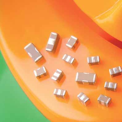
2 Introduction to Knowles Capacitors Introduction to Knowles Capacitors Knowles Capacitors is a global company dedicated to the manufacture of ceramic based electronic components. Knowles has been producing Multilayer Ceramic Capacitors for over 25 years and its employees are committed to providing customers with high quality products together with a fast, friendly and flexible service from a state-of-the-art facility. Production process At the core of Knowles ceramic manufacturing technology is the Wet Process. This fully integrated computer-controlled manufacturing operation is in a clean room environment, and offers unique advantages in the manufacture of filter products. This has resulted in Knowles being a world leader in the manufacture of EMI filters, discoidal capacitors and planar arrays. Our multilayer ceramic manufacturing and filter assembly facility holds a number of internationally recognised approvals including ISO 91. Specific product approvals/qualifications include IECQ CECC, UL, TÜV and AEC-Q2. Products Knowles excellence in ceramic materials technology, combined with EMI filter expertise, has enabled us to offer an unrivalled range of EMI filter products including: l Surface Mount s including: Feedthrough Chip Capacitors Surface Mount C s Surface Mount Pi s X2Y - Integrated Passive Components Benefits Surface Mount EMI s l High capacitance, high voltage, high current Pi filters l FlexiCap termination an option l AEC-Q2 approvals Panel Mount EMI s l Use of Stable and CG/NP ceramics - no Z5U/Y5V l High capacitance values, high voltage l High frequency performance to greater than 1GHz X2Y l Available with FlexiCap termination l AEC-Q2 and medical implantable l Available in surface mount, panel mount and planar array versions Discoidal Capacitors l Small sizes, high capacitance values, high voltage capability l Custom sizes available Planar Arrays l Mechanical superiority, tighter mechanical tolerances l High voltage capability, mixed capacitance values l Available in capacitor and X2Y formats Multiway Assemblies l Can use either discoidal capacitor elements or planar arrays l Full custom design facility Other Knowles products l Multilayer ceramic chip capacitors l High Voltage MLCCs l FlexiCap Capacitors with flexible terminations l StackiCap High CV Capacitors l Class X and Y SMD Safety Certified Capacitors l Radial Leaded Capacitors l AEC-Q2 approved Capacitors l IECQ CECC approved Capacitors l Capacitors for space applications l High Q Ultra-low ESR Capacitors l Non-magnetic Capacitors l High Power Ribbon Leaded l High Temperature Capacitors l Solder-in Panel Mount s l Resin Sealed Ceramic Threaded Panel Mount s l Discoidal Capacitors l Planar Capacitor Arrays
3 Contents General and Technical Introduction EMI s Quick Reference Guide The need for EMI s...4 Explanation of common terms...5 Insertion Loss/ing performance...6 Choice of ceramic dielectric material...7 Panel mount EMI s - Application considerations...8 MIL-STD-461 and EMI s - Common misconceptions...9 Installation of s Contents SM EMI s Introduction...12 Insertion Loss terminal Feedthrough Capacitors (E1 & E7) C and Pi ranges X2Y - Integrated Passive Components (E3) Packaging information Panel Mount EMI s Introduction to Panel Mount EMI s...26 Insertion Loss...27 Solder-in Panel Mount EMI filters Resin Sealed Ceramic Threaded Panel Mount EMI s Discoidals, Planar Arrays and Special s Discoidal and Planar Arrays Special s and Assemblies...8 s for Hi-Rel applications...81 Additional Resources...82 Product Safety Information...83
4 Quick Reference Guide Quick Reference Guide Range Mounting Description Surface Mount Circuit Range E1 Surface Mount 3mA EMI chip. Sizes 85, 126 & 186 C 1pF - 2nF 15/16 E7 Surface Mount 1A to 3A rated EMI chip. Sizes 85, 126, 186 & 1812 C 1pF - 1.8µF 15/16 SBSPP Surface Mount 1A rated Pi filter. Size 126 Pi 22pF - 15nF 17 SBSGC Surface Mount 1A rated C filter. Size 1812 C 1.nF - 22nF 18 SBSGP Surface Mount 5A rated Pi filter. Size 1812 Pi 1.nF - 22nF 19 SBSMC Surface Mount 2A rated C filter. Size 222 C 1.nF - 47nF 2 SBSMP Surface Mount 1A rated Pi filter. Size 222 Pi 1.nF - 47nF 21 E3 Surface Mount Balanced Line chips (X2Y) C 1pF - 1.2µF 22/23 Range Mounting Description SFSSC Solder Discoidal F/T capacitor with leads. 2.3 to 8.75mm body diameter Solder-in Panel Mount Circuit Range Page Page C 1pF - 3.3µF 28 SFSRC Solder Resin Sealed 2.8mm body diameter C 1pF - 47nF 29 SFSTC Solder Resin Sealed 3.25mm body diameter C 1pF - 1nF 3 SFSUC Solder Resin Sealed 5.6mm body diameter C 1pF - 68nF 31 Resin Sealed Ceramic Threaded Range Mounting Description Circuit Range Page SFAAC 4-4 UNC Class 2A thread 4.mm hexagonal head C 1pF - 15nF 32 SFABC 6-32 UNC Class 2A thread 4.mm hexagonal head C 1pF - 15nF 33 SFABL 6-32 UNC Class 2A thread 4.mm hexagonal head L-C 1pF - 15nF 34 SFAJC M3 x.5-6g thread 4.mm hexagonal head C 1pF - 15nF 35 SFAJL M3 x.5-6g thread 4.mm hexagonal head L-C 1pF - 15nF 36 SFAKC M3.5 x.6-6g thread 4.mm hexagonal head C 1pF - 15nF 37 SFAKL M3.5 x.6-6g thread 4.mm hexagonal head L-C 1pF - 15nF 38 SFAKT M3.5 x.6-6g thread 4.mm hexagonal head T 1pF - 15nF 39 SFBCC 8-32 UNC Class 2A thread 4.75mm hexagonal head C 1pF - 15nF 4 SFBCL 8-32 UNC Class 2A thread 4.75mm hexagonal head L-C 1pF - 15nF 41 SFBCP 8-32 UNC Class 2A thread 4.75mm hexagonal head Pi 2pF - 94nF 42 SFBDC UNEF Class 2A thread 4.75mm hexagonal head / 6.35mm flange C 1pF - 15nF 43 SFBDL UNEF Class 2A thread 4.75mm hexagonal head / 6.35mm flange L-C 1pF - 15nF 44 SFBDP UNEF Class 2A thread 4.75mm hexagonal head / 6.35mm flange Pi 2pF - 3nF 45 SFBDT UNEF Class 2A thread 4.75mm hexagonal head / 6.35mm flange T 1pF - 15nF 46 SFBLC M4 x.7-6g thread 4.75mm hexagonal head C 1pF - 15nF 47 SFBLL M4 x.7-6g thread 4.75mm hexagonal head L-C 1pF - 15nF 48 SFBLP M4 x.7-6g thread 4.75mm hexagonal head Pi 2pF - 94nF 49 SFBMC M5 x.8-6g thread 4.75mm hexagonal head / 6.35mm flange C 1pF - 15nF 5 SFBML M5 x.8-6g thread 4.75mm hexagonal head / 6.35mm flange L-C 1pF - 15nF 51 2
5 Quick Reference Guide Range Mounting Description Resin Sealed Ceramic Threaded Circuit Range SFBMP M5 x.8-6g thread 4.75mm hexagonal head / 6.35mm flange Pi 2pF - 3nF 52 SFBMT M5 x.8-6g thread 4.75mm hexagonal head / 6.35mm flange T 1pF - 15nF 53 SFCDC UNEF Class 2A thread 6.35mm hexagonal head C 1pF - 68nF 54 SFCDL UNEF Class 2A thread 6.35mm hexagonal head L-C 1pF - 68nF 55 SFCDP UNEF Class 2A thread 6.35mm hexagonal head Pi 2pF - 3nF 56 SFCMC M5 x.8-6g thread 6.35mm hexagonal head C 1pF - 68nF 57 SFCML M5 x.8-6g thread 6.35mm hexagonal head L-C 1pF - 68nF 58 SFDPP M8 x.75-6g thread 1mm hexagonal head Pi 9.4nF - 94nF 59 SFJGC ¼-28 UNF Class 2A thread 9.8mm round head C 1pF - 3.3µF 6 SFJGL ¼-28 UNF Class 2A thread 9.8mm round head L-C 1pF - 3.3µF 61 SFJGP ¼-28 UNF Class 2A thread 9.8mm round head Pi 66pF - 6.6µF 62 SFJNC M6 x.75-6g thread 9.8mm round head C 1pF - 3.3µF 63 SFJNL M6 x.75-6g thread 9.8mm round head L-C 1pF - 3.3µF 64 SFKBC 6-32 UNC Class 2A thread 4.4mm round head C 1pF - 15nF 65 SFKBL 6-32 UNC Class 2A thread 4.4mm round head L-C 1pF - 15nF 66 SFKKC M3.5 x.6-6g thread 4.4mm round head C 1pF - 15nF 67 SFKKL M3.5 x.6-6g thread 4.4mm round head L-C 1pF - 15nF 68 SFKKT M3.5 x.6-6g thread 4.4mm round head T 1pF - 15nF 69 SFLMC M5 x.8-6g thread 6.mm round head C 1pF - 15nF 7 SFLML M5 x.8-6g thread 6.mm round head L-C 1pF - 15nF 71 SFLMP M5 x.8-6g thread 6.mm round head Pi 2pF - 3nF 72 SFLMT M5 x.8-6g thread 6.mm round head T 1pF - 15nF 73 SFTMC M5 x.8-6g thread 6.35mm hexagonal head C 1pF - 15nF 74 SFUMC M5 x.8-6g thread 6.mm round head C 1pF - 15nF 75 SFJEB ¼-28 UNF Class 2A thread Balanced Line EMI X2Y 4.7nF - 1nF 76 Page Quick Reference Guide Discoidal and Planar Arrays For Discoidal and Planar Arrays see pages 77 to 78. 3
6 The need for EMI s The need for EMI s The use of electronic equipment is ever-increasing, with greater likelihood of interference from other pieces of equipment. Added to this, circuits with lower power levels that are more easily disturbed means that equipment is increasingly in need of protection from EMI (electromagnetic interference). To meet legislation such as the EU Directive on EMC, in addition to other international regulations such as FCC, EMI filtering is now an essential element of equipment design. Introducing screening measures, eg to the case or cables, may suffice in many instances, but some form of low-pass filtering will often be required. Faraday Cage The ideal way of protecting a piece of equipment or circuit from EMI is to totally enclose it in a metal (or conductive) box. This screened enclosure is called a Faraday Cage. Radiated interference is thus prevented from adversely affecting it (Fig 1). Input/output cabling In reality however, most pieces of equipment require input and/ or output connections, perhaps power cables or signal and control lines. The cables providing these connections can act as antennae, able to pick up interference and also to radiate it (Fig 2). Any cable or wire going in through the equipment case can introduce electrical noise, and also radiate it internally onto other wires and circuits. Similarly, it can provide a path to the outside from any noise generated internally, which can also then be radiated and may in turn adversely affect other equipment. 1. Interference can enter a piece of equipment directly through the cabling (conducted interference). 2. Radiated interference can travel directly to the affected equipment. 3. Interference can exit an EMI source via a cable, subsequently to be radiated from the cable and to the affected equipment. 4. Interference can be radiated from an EMI source and then picked up by a cable entering the affected equipment. location - Panel Mount filters To prevent interference entering or leaving a piece of equipment, feedthrough EMI filters can be mounted in the wall of a shielded case. Any incoming or outgoing cables would then pass through the filters. Power or wanted signals pass through the filters unaffected, whilst higher frequency interference is removed. While the screened case protects against radiated interference, the feedthrough filters protect against conducted interference. The integrity of the equipment is thus assured (Fig 3). location - Surface Mount filters Where there is no suitable bulkhead for mounting the filters, pcb types can be used (Fig 4). While this can be an effective method of filtering, it should be noted that in general the insertion loss performance can be reduced at higher frequencies, unless additional screening measures are taken. Good design practices such as short tracks, short connections, close proximity to input and good grounding will help improve insertion loss performance. Faraday Cage Faraday Cage protects against radiated interference Fig 1 EMI source Modes of propagation of EMI 2 Conducted interference Conducted interference 4 Panel mounting feedthrough filters or filter connector input Circuit Feedthrough filters remove conducted interference and provide ultimate performance 1 3 Radiated interference Radiated interference Pcb mounting filters Surface mount filters remove conducted interference, performance reduced due to radiated interference Radiated interference Equipment affected by EMI output Fig 2 Fig 3 Fig 4 4
7 Explanation of common terms Conducted Interference Interference transmitted along a conductor/cable. Protection is provided by a series component. If a feedthrough filter is used to remove conducted interference, and mounted in the wall of a shielded compartment, it provides effective filtering while maintaining the screening integrity. It should be noted that the filter will reduce both emissions and susceptibility. Cut-off Frequency/3dB point The frequency at which filters start to become effective. Generally taken to be at the 3dB point of the attenuation curve. Anything on the line below this frequency will be unaffected. The higher the capacitance of the filter the lower the cut-off, and vice versa. It will also vary depending on source and load impedances. EMC ElectroMagnetic compatibility. A situation wherein two pieces of electrical or electronic equipment are able to function in the same environment without adversely affecting, or being affected by, each other. EMI ElectroMagnetic interference. A broad term covering a wide range of electrical disturbances, natural and man-made, from dc to GHz frequencies and beyond. Sources of disturbance may include radar transmitters, motors, computer clocks, lightning, electrostatic discharge and many other phenomena. Conducted Emissions Signals, unwanted (interference) or otherwise from a piece of equipment. Radiated Interference Interference transmitted in free air. Protection is provided by shielding, but if filters are not used to protect against conducted emissions, the unfiltered lines can act as aerials radiating interference outside the shielded cage. Susceptibility The extent to which a piece of equipment is vulnerable to interference emitted from another piece of equipment. ESD Electrostatic discharge. ESD can result in damage through excessive voltage spikes. We can offer assistance on whether our products can meet specific ESD test requirements. Insertion Loss At a given frequency, the insertion loss of a feedthrough suppression capacitor or filter connected into a given transmission system. Defined as the ratio of voltages appearing across the line immediately beyond the point of insertion, before and after insertion. As measured herein, insertion loss is represented as the ratio of input voltage required to obtain constant output voltage, with and without the component, in the specified 5W system. This ratio is expressed in decibels (db) as follows: Low-pass A filter that lets through dc and low frequency signals, while attenuating (unwanted) high frequency noise. Panel Mount A panel mounted filter that will pass the signal from one side of the wall of a shielded box (or Faraday Cage ) to the other (it feeds the signal through the panel). For effective operation, the filter input and output should be screened from each other, ie there should ideally be no apertures in the panel. Panel mounting feedthrough filters Surface Mount A filter that is suitable for surface mounting on PCBs. It offers improved filtering compared to standard MLCCs, ease of assembly and savings on board space compared to a combination of discrete filter elements. performance at higher frequencies is reduced compared to panel mount types, unless additional shielding measures are taken (see page 1). Working Voltage Continuous operating voltage. This can potentially be across the entire operating temperature range. X2Y Integrated passive component with extremely low self inductance for filtering and de-coupling. For filtering applications: A C1 C2 A Explanation of common terms Insertion loss = 2 log E 1 E 2 Where: E 1 = The output voltage of the signal generator with the component in the circuit. E 2 = The output voltage of the signal generator with the component not in the circuit. When testing is conducted with a network/spectrum analyser, the equipment usually maintains a constant output voltage and can be set to record the output to input voltage ratio in decibels. C1 B For de-coupling applications: SIGNAL C1 C1 RETURN B 5
8 Insertion Loss/ing performance Insertion Loss/ing performance The insertion loss performance is used to aid filter selection by showing signal attenuation at any given frequency. However, it can only ever be a guide as actual performance in service will vary depending on the overall circuit characteristics. Configuration A number of different electrical s are available in feedthrough filters, including the common types shown opposite. A single element filter (a capacitor or an inductor) theoretically provides an insertion loss characteristic of 2dB per decade, a dual element filter (capacitor/inductor) 4dB per decade whilst a triple element filter (Pi or T ) theoretically yields 6dB per decade. In practise, the insertion loss curves do not exactly match the predictions, and the data sheets should be consulted for the realistic figure. The choice of electrical is made primarily on the source and load impedances and may also be influenced by the level of attenuation required at various frequencies. C This is a feedthrough capacitor with low self inductance. It shunts high frequency noise to ground and is suitable for use with a high impedance source and load. L-C This is a feedthrough filter with an inductive element in combination with a capacitor. It is commonly used in a circuit with a low impedance source and a high impedance load (or vice versa). The inductive element should face the low impedance. Source and Load Impedances Insertion loss figures are normally published for a 5Ω source and 5Ω load circuit. In practise the impedance values will probably be very different, which could result in either an increase or decrease in insertion loss. The electrical of the filter (the capacitor/inductor combination) should be chosen to optimise Load Current For filters which include ferrite inductors, the insertion loss under load current may be less than that with no load. This is because the ferrite material saturates with current. The reduction in insertion loss depends on the current and the characteristics of the Insertion loss is determined by: l l Source/load impedances l The load current (which can cause ferrite saturation) l Ceramic dielectric materials. The capacitance change will be affected by applied voltage, temperature and the age of the part l Earthing impedance l Shielding integrity C Pi THREAD L-C C-L Pi This is a feedthrough filter with 2 capacitors and an inductive element between them. Ideally, it should be used where both source and load impedances are high. T This is a feedthrough filter with 2 series inductive elements separated by one feedthrough capacitor. It is suitable for use where both source and load impedances are low. Multi-element filters These filters contain more than 3 elements, for example L-C-L-C-L filters. The addition of further elements increases the steepness of the insertion loss curve. T THREAD the filter performance for that particular source/load impedance situation. An estimate of insertion loss for source and load impedances other than 5Ω may be possible. Please contact our Sales Office. particular ferrite material. In extreme cases the ferrite will become ineffective and insertion loss will appear to be the same as for a C filter. For further information contact the Sales Office. Attenuation Curve A plot of insertion loss versus frequency on a logarithmic scale. Insertion Loss (db) Frequency (MHz)
9 Choice of ceramic dielectric material When choosing a filter, it is important to be aware of the different performance characteristics that may be available from different categories of ceramic materials employed in their capacitors. Generally, stability of dielectric constant (and therefore filter capacitance value), with respect to some operational and environmental parameters, deteriorates with increasing dielectric constant. Specific factors which affect dielectric constant are temperature, voltage, frequency and time (ageing). The three main classifications of ceramic dielectric employed in the manufacture of EMI filters are generally referred to as ultra stable (CG/NP), stable () and general purpose (Z5U, Y5V or X7W). Summary of ceramic dielectric characteristics Spread of capacitance values The capacitance of a ceramic capacitor can change as a result of a change in temperature, applied voltage and age. Please note that this potential change can lead to a significant drop in filtering performance. Consider the typical performance of 5,pF filter capacitors, offered in standard dielectric classifications, operating at a voltage of 1Vdc at 85 C, at an age of 1, hours. The final capacitance CG/NP Z5U Y5V X7W EIA dielectric classification Ultra stable Stable General purpose temperature range Maximum capacitance change over temperature range (no voltage applied) Ageing characteristics -1ºC to +85ºC -3ºC to +85ºC -55ºC to +125ºC ±3 ppm/ C ±15% % % +4-9% Zero <2% per time decade CG/NP Most parameters for materials in this dielectric classification remain unaffected by temperature, voltage, frequency or time. Stabilities are measured in terms of parts per million but dielectric constants are relatively low (1 to 1). This is a classification for materials which are relatively stable with respect to temperature, voltage, frequency and time. Typical dielectric constants would be of the order 2, to 4,, enabling the achievement of far higher capacitance values for a given size of capacitor than can be gained from CG/NP materials. If the voltage coefficient (VC) is critical, are also able to offer parts with BX (2X1) and BZ (2C1) VC characteristics. Refer to the factory for further details. Z5U/Y5V/X7W These are classifications for materials which are severely restricted and performance under applied voltage may be seriously compromised. A summary of the specifications of these materials follows. Please note that uses only the higher performance CG/NP and in its standard ranges. 6% per time decade 6% per time decade 6% per time decade value can fall within the range of values (see chart below), taking into account the ageing process and effects of temperature and voltage as shown in the chart above. It is clear that the capacitance can change as a result of an increase (or decrease) in temperature, applied voltage and as a result of ageing. If the capacitance has reduced, so too will the insertion loss performance. Choice of ceramic dielectric material 9pF negligible change 575pF to 35pF 61pF to 1pF 61pF to 5pF 854pF to 25pF 8pF 7pF only uses these two dielectrics 6pF 5pF Nominal 4pF 3pF 2pF 1pF pf CG/NP Z5U Y5V X7W 7
10 Panel Mount EMI s - Application considerations Panel Mount EMI s - Application considerations Thread size or head size? What s the crucial factor in spacing The thread size has no relevance to the mounting pitch, but can influence cost. Very small threads are harder to work with, but offer little or no gain over larger thread sizes. If close mounting pitch is important, change instead to a round body. Mounted using modified screwdriver blades, this of component removes the need to allow space for mounting sockets and allow components to be mounted almost touching each other. offer a full range of round head filter types - SFKB, SFKK, SFLM and SFUM. Special requirements can also be considered. Schematic showing the pitch improvement that can be gained with round head filters compared to traditional hexagon heads. Hermetic seals vs resin seals Resin sealed filters have epoxy encapsulants injected into the cavities either side of the filter elements. The purpose of the resin is to ruggedise the assembly, supporting the pins and sealing the ceramic to prevent reliability issues such as moisture ingress. Poor encapsulants can be susceptible to cracking away from the metalwork due to temperature change. This can then allow moisture ingress which can result in reliability concerns. They can also exert a force on the ceramic which can result in cracking causing electrical failure. MIL or Space specifications generally do not demand resin sealed filters be tested for immersion or accelerated damp heat testing. resin sealed filters use a very high purity, highly filled, epoxy encapsulant with a very low co-efficient of thermal expansion very closely matched to the expansion co-efficient of the ceramic and other materials used in the construction. These characteristics enable filters to be thermally cycled with very little stress being applied to the ceramic elements and with reduced risk of cracking allowing moisture ingress. Certain filters have successfully passed immersion and accelerated damp heat testing. Screw mount hermetic filters generally have glass to metal seals soldered into place instead of conventional resin seals. They are better than resin sealed filters in applications where outgassing is critical, or where the environment is particularly harsh. MIL or Space specifications generally do require hermetically sealed filters be tested for immersion or accelerated damp heat testing. Unless fitted with sealing rings, they will not normally provide a gas seal between either side of the mounting bulkhead the seal is to protect the internal capacitor elements. Solder mount hermetic filters may create a gas seal between either side of the bulkhead, but this is more dependent on the sealing capabilities of the solder joint mounting the filter rather than the filter seal. Usually, solder mount filters only have a glass seal on one side of the filter body, with the other end resin sealed. Test plans are normally the same as those for resin sealed filters. Hermetically sealed solder mount filters are only normally required in applications where one end of the filter will be exposed to harsh environments, or where outgassing is critical on one side of the panel. Please note: Knowles do not currently offer hermetic EMI filters. Discoidal capacitor vs tubular capacitor The original panel mount filters used single layer tubular capacitors. There is one major advantage of this type of capacitor - it lends itself to very easy Pi filter construction. For this reason, Pi filters have tended to be considered the optimum filter. As performance demands increased, higher capacitance values were required. High K, unstable (Z5U / Y5V see page 7) dielectrics and multilayer tubes began to be used. These use buried layer electrodes within the tube walls, but the reduced dielectric thickness resulted in lower voltage withstand capability. The unstable dielectrics result in poor performance over the voltage and temperature ranges. Tubular capacitors have one major flaw - the thin ceramic walls make them very prone to cracking causing electrical failures. As MLCC chip capabilities developed, the discoidal capacitor appeared in filters. These devices use MLCC chip technology to produce a very low inductance (low ESL / low ESR) capacitor giving improved performance and higher capacitance and voltage ranges (higher capacitance per unit voltage). They are physically much stronger and robust than tubes. Most panel mount filters use discoidal capacitors for optimum mechanical strength and high quality or CG/NP dielectric materials for optimum electrical performance. However, there are other dielectric materials used in the manufacture of filters. Tube based filters Disc based filters Tubular capacitor Advantages Cheap. Suited to Pi filter manufacture. Robust. High capacitance. C, L-C, & T circuits easy. Very high capacitance Pi filters possible. Tight tolerance possible. Vc characteristics possible. Multilayer discoidal capacitor Seal Disadvantages Low capacitance only, not robust easily cracked multilayer tubes = higher capacitance but low voltage. Low capacitance Pi filters, relatively expensive. Typical construction of a Pi filter using tubular capacitors. Seal Typical construction of a Pi filter using multilayer discoidal capacitors. Seal Seal 8
11 MIL-STD-461 & EMI s - Common misconceptions We routinely get filter enquiries that are typically quoting filters must meet the requirements MIL- STD-461 or filters must comply with MIL-STD-461. This is a complete mis-understanding of MIL-STD-461 and needs to be clarified with the customer. The following might be useful. The US MIL-STD-461 specification sets regulations for the control of electromagnetic interference emissions and susceptibility of equipment. It sets requirements for the levels of emissions allowed to be exported from electrical equipment and it also sets requirements as to the susceptibility levels of equipment from external noise sources. In addition it gives guidelines on measuring those features of the equipment. A piece of electrical equipment behaves as a source and will generate EMI. That EMI will be transmitted by conduction and radiation, and be incident upon a receiver (which may be another piece of electrical equipment or a test fixture). The level of the electromagnetic signature of the conducted emissions is determined by the characteristics of the equipment; e.g. SMPS s may be noisy, filament lights may be quiet. If the levels of emissions from the equipment exceed the limits set in MIL-STD-461, then they need to be attenuated by using an EMI filter. The performance of that filter across the frequency spectrum must be to allow the equipment emissions to be suppressed to a level low enough to allow the equipment to claim compliance with the limits of the specification. That filter performance requirement is determined by the electromagnetic signature of the equipment, and what limits are required to be achieved. The filter manufacturer of course can only get this information from the manufacturer of the equipment. Then the claim for compliance can normally be verified by test and measurement. This explains why no filter manufacturer can claim that their filters meet MIL-STD-461; it is not the filter which meets the specification, but the equipment or platform. The situation might be that a filter proposed is above specification requirement, and the equipment conforms to MIL-STD-461 very comfortably. On the other hand, equipment in the system may be so electromagnetically noisy that a proposed filter fails to support the equipment in meeting the limits of MIL-STD-461. are not able to guarantee that the incorporation of a particular filter into the Client s equipment will enable system compliance with the emissions limits of specification MIL-STD-461. All filter manufacturers catalogue their filter performance as insertion loss in a reference (normally 5Ω) impedance system. The filter manufacturer does not know the level of emissions associated with a piece of equipment, nor the real-world terminating impedances as presented to the filter. Hence the published filter insertion loss performance at/across a particular frequency range will not necessarily represent the equivalent attenuation of equipment emissions in application and the equipment manufacturer will need to conduct their own tests to determine the part is suitable and the filtered equipment meets the requirements of MIL-STD-461. In summary MIL-STD-461 is an equipment specification and cannot be applied to filters. We understand some filter manufacturers may be quoting MIL-STD-461 in their literature, but this is either lack of understanding of the specification, or salesmanship. It is the responsibility of the equipment manufacturer to meet MIL-STD-461, and no filter supplier can ever properly quote it. If we have a filter enquiry where the customer refers to MIL- STD-461, we need to ask exactly what level of attenuation they require. We can then suggest part numbers based on that detail, but ultimately they will need to test parts to determine if they are suitable. Professional EMC test houses may be able to help suggesting requirements as well. C Radiated emissions R are blocked by the casing design. Conducted emissions & Radiated emissions as a result of conducted emissions C are resolved by using appropriate filters in the case housing. To define the filter, the ratio of emissions C to the requirements of MIL-STD-461 must be known. R MIL-STD-461 & EMI s - Common misconceptions 9
12 Installation of s Installation of s Surface Mount and Panel Mount Solder-in filters Solder pad layouts are included with the detailed information for each part. Recommended soldering profile See text for maximum temperature Temp Soldering of filters Pre-heat Gradual warm-up to reflow Do not thermal shock Natural cool down Do not force cool Time The soldering process should be controlled such that the filter does not experience any thermal shocks which may induce thermal cracks in the ceramic dielectric. The pre-heat temperature rise of the filter should be kept to around 2 C per second. In practice successful temperature rises tend to be in the region of 1.5 C to 4 C per second dependent upon substrate and components. The introduction of a soak after pre-heat can be useful as it allows temperature uniformity to be established across the substrate thus preventing substrate warping. The magnitude or direction of any warping may change on cooling, imposing damaging stresses upon the filter. Soak Reflow Cool E1, E3, E7 SBSP ranges are compatible with all standard solder types including lead-free, maximum temperature 26 C. For SBSG, SBSM and SFSS ranges, solder time should be minimised, and the temperature controlled to a maximum of 22 C. For SFSR, SFST and SFSU ranges the maximum temperature is 25 C. Cooling to ambient temperature should be allowed to occur naturally. Natural cooling allows a gradual relaxation of thermal mismatch stresses in the solder joints. Draughts should be avoided. Forced air cooling can induce thermal breakage, and cleaning with cold fluids immediately after a soldering process may result in cracked filters. Note: The use of FlexiCap terminations is strongly recommended to reduce the risk of mechanical cracking. Soldering to axial wire leads Soldering temperature The tip temperature of the iron should not exceed 3 C. Dwell time Dwell time should be 3-5 seconds maximum to minimise the risk of cracking the capacitor due to thermal shock. Heat sink Where possible, a heat sink should be used between the solder joint and the body, especially if longer dwell times are required. Bending or cropping of wire leads Bending or cropping of the filter terminations should not be carried out within 4mm (.157 ) of the epoxy encapsulation, the wire should be supported when cropping. Soldering irons should not be used for mounting surface mount filters as they can result in thermal shock damage to the chip capacitor. A more comprehensive application note covering installation of all products is available on the website. 1
13 Installation of s Resin filled screw mounted EMI s General The ceramic capacitor, which is the heart of the filter, can be damaged by thermal and mechanical shock, as well as by overvoltage. Care should be taken to minimise the risk of stress when mounting the filter to a panel and when soldering wire to the filter terminations. Mounting to Chassis It is important to mount the filter to the bulkhead or panel using the recommended mounting torque, otherwise damage may be caused to the capacitor due to distortion of the case. When a threaded hole is to be utilised, the maximum mounting torque should be 5% of the specified figure which relates to unthreaded holes. For details of torque figures for each filter range, please see below. Tools Hexagonal devices should be assembled using a suitable socket. Round bodied filters may be fitted to the panel in one of two ways (and should not be fitted using pliers or other similar tools which may damage them): Round bodies with slotted tops are designed to be screwed in using a simple purpose-designed tool. Round bodies without slotted tops are intended to be inserted into slotted holes and retained with a nut. The thread has flats machined to engage with the flats in the hole. Grounding To ensure the proper operation of the filters, the filter body should be adequately grounded to the panel to allow an effective path for the interference. The use of locking adhesives is not recommended, but if used should be applied after the filter has been fitted. Minimum plate thickness Users should be aware that the majority of these filters have an undercut between the thread and the mounting flange of the body, equal to 1.5 x the pitch of the thread. Mounting into a panel thinner than this undercut length may result in problems with thread mating and filter position. It is recommended that a panel thicker than this undercut length be used wherever possible. Maximum plate thickness This is specified for each filter in order that the nut can be fully engaged even when using a washer. Soldering to axial wire leads Soldering temperature The tip temperature of the iron should not exceed 3 C. Dwell time Dwell time should be 3-5 seconds maximum to minimise the risk of cracking the capacitor due to thermal shock. Heat sink Where possible, a heat sink should be used between the solder joint and the body, especially if longer dwell times are required. Bending or cropping of wire leads Bending or cropping of the filter terminations should not be carried out within 4mm (.157 ) of the epoxy encapsulation, the wire should be supported when cropping. RoHS Compliance All surface mount filters, resin sealed panel mount filters and power filters can be supplied fully RoHS compliant (211/65/EU) through material exemption. Please contact our Sales Office for further details. Care must be taken not to exceed the maximum soldering temperatures of surface mount parts. Standard hermetic sealed panel mount filters use SnPb solders as part of their assembly and are intended for exempt applications such as aerospace or military. Substitution of the SnPb solder with Pb free solders may be possible to create a RoHS compliant part, subject to quantities please refer to the Sales Office for more information. Installation of s 11

 terminals. The signal is carried through the internal electrodes.")
 2.")
14 Introduction to Surface Mount EMI s Introduction to Surface Mount EMI s Surface Mount s are designed to be mounted directly to printed circuit boards using conventional mounting techniques in the same way as standard MLCC s. They are categorised into 3 distinct families: 1. E1 / E7 C EMI Chips (also known as 3-terminal chips) These use conventional MLCC manufacturing techniques to form a filter which is short circuit end-to-end and has a capacitance between the end terminals and the side (ground) terminals. The signal is carried through the internal electrodes. The current carrying capacity is defined by the cross section and number of the electrodes in the filter and is therefore linked with the capacitance of the filter. Compared to conventional 2-terminal MLCC devices the internal inductance between line and ground is reduced, giving improved attenuation. Loss (db) 2. Surface mount Pi / C s Pi filters incorporate 2 capacitors and an inductor together to make a multi-element filter, giving sharper cut-off and better low frequency performance than straight C filters. The range of SM Pi filters use conventional MLCC manufacturing techniques to form the capacitive element of the filter, but the inductive element is created separately either by means of a bead inductor placed over a through conductor pin, or by means of a buried layer surface mount inductor with the signal carried by the buried internal layers. Current carrying capacity is defined by the characteristics of the conductor and is independent to the capacitance of the filter Comparison of 3.3nF SM filter types SBSPP MLCC Feedthrough chip Solder connections are made to each end (signal lines) and each side band (earth or ground) Frequency (MHz) 3. X2Y s X2Y filters are manufactured in the same way as conventional MLCC s but have a special internal architecture that results in ultra-low ESL (Equivalent Series Inductance) through opposing current flows in adjacent parallel plates. They are not feedthrough devices, but act as bypass filters so are not current limited - the only signal passing through the chip is the filtered noise to ground. They are ideal for twin-line applications such as motors, amplifier inputs or twisted pair (balanced line) applications, where they are fitted between the lines with the centre terminal taken to ground. Incorporating the capacitors in a single ceramic element eliminates any capacitance shift through temperature variation. 12
15 Insertion Loss Insertion Loss figures Insertion loss plots and figures supplied are typical only and are measured on 5Ω stripline open boards,.8mm thick FR4 with gold plated tracks. Solder pads are T bar with respect to the track and dimensionally match the recommendations given. The boards are mounted to brass support jigs for mechanical stability and electrical grounding. All measurements are taken using a Vector Network Analyser in a 5Ω system, no load. Earth track E1/E7 SBSP SBSG SBSM s mounted on open pcb Pi-filter Input track PCB Output track Insertion Loss Improved shielding Signal track Signal track Signal track Signal track Faraday cage It is important to recognise that the board material, thickness and layout, the plating finish, the grounding efficiency and the circuit impedances will all have an effect on the actual performance of the filter in operation. The effect of the board makes it difficult to directly compare parts unless the mounting details are defined. It is therefore important to test the filters in circuit to determine the performance level achieved. Input track Pi-filter Dirty area Via Ground plane PCB Clean area Output track Effects of mounting method on Insertion Loss C and Pi filters are mounted to PCBs and soldered in identical manner to chip capacitors. Solder connections made to each end (signal lines) and each side band (earth track). Whilst SBSG, SBSM and SBSP filters can be mounted conventionally on PCBs, they are also suitable for mounting in a wall or partition on a board. This greatly improves the screening between filter input and output, thereby enhancing the high frequency response. The following insertion loss curves based on actual measurements, show the effect. It can be seen that the filters conventionally mounted exhibit a drop in attenuation at higher frequencies. Shielding methods maintain improved suppression characteristics to 1GHz and above. Loss (db) Surface Mount 68nF Pi mounted on open stripline test board Surface Mount 68nF Pi mounted in shielding bulkhead Panel Mount 66nF Pi mounted on shielding bulkhead Frequency (MHz) 13
16 E1 & E7 Insertion Loss SBSPP Insertion Loss Open Board Stripline jig. 5ohm System Loss (db) Loss (db) EMI chip Insertion Loss - SM High Current and Pi s 1pF - CG 22pF - CG 47pF - CG 1pF - CG 47pF - CG 2.2nF - CG 2.2nF - 4.7nF - 1nF - 22nF - 1nF - 2nF SBSPP 47pF SBSPP 22pF -5 SBSPP 2.2nF -6 SBSPP 1nF -7 SBSPP 47nF SBSPP 15nF K 2K 1 See page 15/ Loss (db) Loss (db) SBSGC 1.nF -5 SBSGP 4.7nF -6 SBSGC 1nF -6 SBSGP 1nF SBSGC 47nF -7 SBSGC 22nF SBSGP 47nF SBSGP 22nF Frequency (MHz) 1 SBSMP Insertion Loss Open Board Stripline jig. 5ohm System Loss (db) Loss (db) 1 See page 19 SBSMC Insertion Loss Open Board Stripline jig. 5ohm System SBSMC 1.5nF -5 SBSMP 4.7nF -6 SBSMC 4.7nF -6 SBSMP 1nF SBSMC 47nF -7 SBSMC 47nF 1 1 Frequency (MHz) See page Frequency (MHz) See page SBSGP Insertion Loss Open Board Stripline jig. 5ohm System See page 17 SBSGC Insertion Loss Open Board Stripline jig. 5ohm System -7 1 Frequency (MHz) Frequency (MHz) SBSMP 68nF SBSMP 47nF Frequency (MHz) See page 21

17 L Surface Mount EMI s - E1 & E7 feedthrough capacitors The E1 and E7 ranges of feedthrough MLCC chip C filters are 3 terminal chip devices designed to offer reduced inductance compared to conventional MLCCs when used in signal line filtering. The filtered signal passes through the chip internal electrodes and the noise is filtered to the grounded side contacts, resulting in reduced length noise transmission paths. Available in CG/NP and dielectrics, with current ratings of 3mA, 1A, 2A, 3A and voltage ratings of 25Vdc to 2Vdc. Also available with FlexiCap termination which is strongly recommended for new designs. Commonly used in automotive applications, a range qualified to AEC-Q2 is also available. EMI chip E1 3mA, E7 1A/2A/3A C E1/E7 Recommended solder lands D T Earth track B E A W B2 B1 C Dimensions Signal track L W T B1 B ±.3 (.79 ±.12) 1.25 ±.2 (.49 ±.8) 1. ±.15 (.39 ±.6).6 ±.2 (.24 ±.8).3 ±.15 (.12 ±.6) 3.2 ±.3 (.126 ±.12) 1.6 ±.2 (.63 ±.8) 1.1 ±.2 (.43 ±.8).95 ±.3 (.37 ±.12).5 ±.25 (.2 ±.1) 4.5 ±.35 (.177 ±.14) 1.6 ±.2 (.63 ±.8) 1.1 ±.2 (.43 ±.8) 1.4 ±.3 (.55 ±.12).5 ±.25 (.2 ±.1) 4.5 ±.35 (.177 ±.14) 3.2 ±.3 (.126 ±.12) 2. ±.3 (.79 ±.12) 1.45 ±.35 (.55 ±.12).75 ±.25 (.2 ±.1) A.95 (.37) 1.2 (.47) 1.2 (.47) 2.65 (.14) B.9 (.35).9 (.35) 1.4 (.55) 1.4 (.55) C.3 (.12).6 (.24).8 (.31).8 (.31) D.4 (.16).8 (.31) 1.4 (.55) 1.4 (.55) E.75 (.3) 1. (.39) 1. (.39) 2.5 (.8) Notes: 1) All dimensions mm (inches). 2) Pad widths less than chip width gives improved mechanical performance. 3) The solder stencil should place 4 discrete solder pads. The unprinted distance between ground pads is shown as dim E. 4) Insulating the earth track underneath the filters is acceptable and can help avoid displacement of filter during soldering but can result in residue entrapment under the chip. Standard Range - E1 & E7 Feedthrough Capacitors E1 E7 Chip Size Max Current 3mA 3mA 3mA 1A 2A 2A 3A Voltage Dielectric Minimum and maximum capacitance values 25Vdc 5Vdc 1Vdc 2Vdc CG/NP 18pF-1.5nF 56pF-3.9nF 82pF-4.7nF 18pF-1.5nF 56pF-3.9nF 82pF-4.7nF - 47pF-1nF 5.6nF-33nF 3.9nF-56nF 82pF-1nF 1nF-33nF 22nF-56nF 56nF-1.8µF CG/NP 22pF-82pF 22pF-3.3nF 22pF-3.9nF 1pF-22pF 22pF-1nF 1pF-1.5nF - 56pF-68nF 4.7nF-22nF 3.3nF-33nF 1nF-68nF 1nF-22nF 22nF-33nF 33nF-1.5µF CG/NP 22pF-56pF 22pF-2.2nF 22pF-3.3nF 1pF-12pF 22pF-56pF 1pF-68pF - 56pF-27nF 1.8nF-1nF 3.3nF-18nF 1nF-27nF 1nF-1nF 22nF-18nF 18nF-82nF CG/NP - 56pF-1.2nF 56pF-1nF - 15pF-18pF 56pF-47pF nF-56nF 3.9nF-1nF - 12nF-56nF 22nF-1nF 1nF-27nF Note: E7 25Vdc CG/NP 126 and 186 ranges in green, have maximum current of 1A. AEC-Q2 Qualified Range - E1 & E7 Feedthrough Capacitors - maximum capacitance values E1 E7 Chip Size V CG/NP 82pF 1nF 2.2nF 22pF 1nF 1.5nF 47nF 1nF 2nF 47nF 1nF 2nF 1V CG/NP 56pF 1nF 2.2nF 12pF 56pF 68pF 15nF 15nF 68nF 15nF 15nF 68nF Notes: = AEC-Q2. For some lower capacitance parts, higher voltage rated parts may be supplied. 15
18 EMI chip Surface Mount EMI s - E1 & E7 feedthrough capacitors Open board insertion loss performance in 5W system Open Board Performance.1MHz 1MHz 1MHz 1MHz 1GHz Resonance Freq (MHz) approx. 1pF 22pF 33pF 47pF 68pF 1pF 15pF 22pF 33pF 47pF 56pF 68pF 82pF 1nF 1.5nF 2.2nF 3.3nF 4.7nF 6.8nF 1nF 15nF 22nF 33nF 47nF 68nF 1nF 15nF 22nF 33nF 47nF 56nF Note: For Insertion Loss graph see page Loss (db) -2 1pF - CG 22pF - CG 47pF - CG 1pF - CG 47pF - CG 2.2nF - CG 2.2nF - 4.7nF - 1nF - 22nF - 1nF - 2nF K 2K Frequency (MHz) Ordering Information - E1 & E7 feedthrough capacitors 126 Y 1 13 M X T E7 Chip size Termination Voltage in picofarads (pf) Tolerance Dielectric Packaging J = Nickel Barrier (Tin) *Y = FlexiCap (Tin - only) A = (Tin/Lead) Not RoHS compliant. *H = FlexiCap (Tin/Lead) Not RoHS compliant. 25 = 25V 5 = 5V 1 = 1V 2 = 2V First digit is. Second and third digits are significant figures of The fourth digit is number of M = ±2% A = CG/NP AEC-Q2 T = 178mm (7 ) reel E1 E7 C = CG/NP R = 33mm (13 ) reel E = AEC-Q2 Example: 13 = 1pF. B = Bulk X = Note: *FlexiCap termination only available in material. Please contact our Sales Office for any special requirements. Reeled quantities mm (7 ) reel mm (13 ) reel
19 SBSPP CG/NP & Dimensions L 3.2±.3 (.126 ±.12 ) W 1.65±.3 (.65 ±.12 ) T 1.6±.2 (.63 ±.8 ) B1 C.95±.3 (.37 ±.12 ) B2.5±.25 (.2 ±.1 ) Suggested mounting pad details T W L B2 B1 Details Configuration Measurement Insulation Resistance (IR) Ferrite Inductance (Typical) Terminals & - End & Side 1hr Point 1A 1GW or 1WF.3µH (@ 1MHz) Pi Sn plated over FlexiCap Termination SBSPP E = Unprinted solder area between ground pads D A 1.2 (.47 ) B.9 (.35 ) C.6 (.24 ) Construction Ceramic Multi Layer Chip Capacitor Multi Layer Ferrite Bead Inductor Connection via FlexiCap Termination.7g (.25oz) E B C A F D.8 (.3 ) E 1. (.39 ) F 2.9 (.114 ) Reeled quantities SBSPP 178mm (7 ) reel 15 It is recommended that designers independently confirm pad dimensions are acceptable, particularly with respect to higher working voltages. (±2%) Dielectric Voltage (dc) (dc) Approximate Resonant Frequency (MHz) *.1MHz 1MHz 1MHz 1MHz 1GHz SBSPP122MC 22pF SBSPP147MC 47pF SBSPP111MC 1pF CG/NP SBSPP1221MC 22pF SBSPP1471MC 47pF SBSPP112MX 1.nF SBSPP1152MX 1.5nF SBSPP1222MX 2.2nF SBSPP1332MX 3.3nF SBSPP1472MX 4.7nF SBSPP1682MX 6.8nF SBSPP113MX 1nF SBSPP1153MX 15nF SBSPP5223MX 22nF SBSPP5333MX 33nF SBSPP5473MX 47nF SBSPP5683MX 68nF SBSPP514MX 1nF SBSPP5154MX 15nF * Insertion Loss performance quoted is measured on an open FR4 board mounted on a brass backplane in a 5Ω system. Performance curves can be supplied on request. Performance in circuit is liable to be different and is affected by board material, track layout, grounding efficiency and circuit impedances. Shielding can be used to improve high frequency performance. Ordering Information - SBSPP range SB S P P M X B Size Voltage (dc) in picofarads (pf) Tolerance Dielectric Packaging Board Surface Mount Size Code P (nominally 126) P = Pi 25 = 25V 5 = 5V 1 = 1V First digit is. Second and third digits are significant figures of zeros following Example: 472 = 47pF 153 = 15pF M = ±2% C = CG/NP X = T=178mm (7 ) reel R=33mm (13 ) reel B = Bulk Options include for example: change of finish / alternative voltage rating / non-standard intermediate capacitance values / test requirements. Please refer specific requests to the factory. 17
20 SBSGC SBSGC Dimensions L1 4.55±.25 (.179 ±.1 ) L2 4.7±.4 (.185 ±.15 ) W 3.2±.2 (.126 ±.8 ) CT 2.5±.15 (.98 ±.6 ) B1 1.5±.4 (.59 ±.15 ) B2.3±.25 (.12 ±.1 ) B2 L2 L1 W B1 Tin plated solderable termination area Solder joint from filter manufacture T Details Configuration Measurement Insulation Resistance (IR) Ferrite Inductance (Typical) Terminals & - End 1hr Point 1A 1GW or 1WF N/A SnAg solder over Sn Plate C Suggested mounting pad details E = Unprinted solder area between ground pads D A 2.65 (.14 ) B 1.4 (.55 ) Terminals & - Side Reflow Temperature Construction Sn Plated 22ºC max. Ceramic Multi Layer Chip Capacitor Copper Alloy Through Conductor Soldered End Connections C.8 (.31 ).2g (.7oz) E A F D 1.4 (.55 ) B C E 2.5 (.8 ) F 5.8 (.228 ) Reeled quantities SBSGC 178mm (7 ) reel 5 It is recommended that designers independently confirm pad dimensions are acceptable, particularly with respect to higher working voltages. (±2%) Dielectric Voltage (dc) (dc) Approximate Resonant Frequency (MHz) *.1MHz 1MHz 1MHz 1MHz 1GHz SBSGC512MX 1.nF SBSGC5152MX 1.5nF SBSGC5222MX 2.2nF SBSGC5332MX 3.3nF SBSGC5472MX 4.7nF SBSGC5682MX 6.8nF SBSGC513MX 1nF SBSGC5153MX 15nF SBSGC5223MX 22nF SBSGC5333MX 33nF SBSGC5473MX 47nF SBSGC2683MX 68nF SBSGC114MX 1nF SBSGC1154MX 15nF SBSGC5224MX 22nF * Insertion Loss performance quoted is measured on an open FR4 board mounted on a brass backplane in a 5Ω system. Performance curves can be supplied on request. Performance in circuit is liable to be different and is affected by board material, track layout, grounding efficiency and circuit impedances. Shielding can be used to improve high frequency performance. Ordering Information - SBSGC range SB S G C M X B Size Voltage (dc) in picofarads (pf) Tolerance Dielectric Packaging Board Surface Mount Size Code G (nominally 1812) C = C 5 = 5V 1 = 1V 2 = 2V 5 = 5V First digit is. Second and third digits are significant figures of zeros following Example: 472 = 47pF 683 = 68pF M = ±2% X = T = 178mm (7 ) reel R = 33mm (13 ) reel B = Bulk Options include for example: change of finish / alternative voltage rating / non-standard intermediate capacitance values / test requirements. Please refer specific requests to the factory. 18
21 SBSGP Dimensions L1 4.55±.25 (.179 ±.1 ) L2 5.25±.4 (.27 ±.15 ) W 3.2±.2 (.126 ±.8 ) CT 2.5±.15 (.98 ±.6 ) B1 1.5±.4 (.59 ±.15 ) B2.3±.25 (.12 ±.1 ) B2 L2 L1 B1 W Tin plated solderable termination area Solder joint from filter manufacture T Details Configuration Measurement Insulation Resistance (IR) Ferrite Inductance (Typical) Terminals & - End 1hr Point 5A 1GW or 1WF.7µH (@ 1kHz) SnAg solder over Sn Plate Pi SBSGP Suggested mounting pad details E = Unprinted solder area between ground pads E D A F A 2.65 (.14 ) B 1.4 (.55 ) C.8 (.31 ) D 1.4 (.55 ) Terminals & - Side Reflow Temperature Construction Sn Plated 22ºC max. Ceramic Multi Layer Chip Capacitor Copper Alloy Through Conductor Ferrite Bead Inductor Soldered End Connections.2g (.7oz) B C E 2.5 (.8 ) F 5.8 (.228 ) It is recommended that designers independently confirm pad dimensions are acceptable, particularly with respect to higher working voltages. Reeled quantities SBSGP 178mm (7 ) reel 5 (±2%) Dielectric Voltage (dc) (dc) Approximate Resonant Frequency (MHz) *.1MHz 1MHz 1MHz 1MHz 1GHz SBSGP512MX 1.nF SBSGP5152MX 1.5nF SBSGP5222MX 2.2nF SBSGP5332MX 3.3nF SBSGP5472MX 4.7nF SBSGP5682MX 6.8nF SBSGP513MX 1nF SBSGP5153MX 15nF SBSGP5223MX 22nF SBSGP5333MX 33nF SBSGP5473MX 47nF SBSGP2683MX 68nF SBSGP114MX 1nF SBSGP1154MX 15nF SBSGP5224MX 22nF * Insertion Loss performance quoted is measured on an open FR4 board mounted on a brass backplane in a 5Ω system. Performance curves can be supplied on request. Performance in circuit is liable to be different and is affected by board material, track layout, grounding efficiency and circuit impedances. Shielding can be used to improve high frequency performance. Ordering Information - SBSGP range SB S G P M X B Size Voltage (dc) in picofarads (pf) Tolerance Dielectric Packaging Board Surface Mount Size Code G (nominally 1812) P = Pi 5 = 5V 1 = 1V 2 = 2V 5 = 5V First digit is. Second and third digits are significant figures of zeros following Example: 472 = 47pF 683 = 68pF M = ±2% X = T = 178mm (7 ) reel R = 33mm (13 ) reel B = Bulk Options include for example: change of finish / alternative voltage rating / non-standard intermediate capacitance values / test requirements. Please refer specific requests to the factory. 19
22 SBSMC SBSMC Dimensions L1 5.7±.4 (.224 ±.15 ) L2 6.6±.4 (.26 ±.15 ) W 5.±.4 (.197 ±.15 ) CT 3.18±.2 (.125 ±.8 ) B1 2.25±.4 (.88 ±.15 ) B2.3±.25 (.12 ±.1 ) B2 L2 L1 W B1 Tin plated solderable termination area Solder joint from filter manufacture T Details Configuration Measurement Insulation Resistance (IR) Ferrite Inductance (Typical) Terminals & - End 1hr Point 2A 1GW or 1WF N/A ( C Section) SnCu solder over Sn Plate C Suggested mounting pad details E = Unprinted solder area between ground pads D A 1. (.394 ) B 2.35 (.93 ) Terminals & - Side Reflow Temperature Construction Sn Plated 22ºC max. Ceramic Multi Layer Chip Capacitor Copper Alloy Through Conductor Soldered End Connections C 1.35 (.53 ).65g (.23oz) E F A D 2. (.79 ) E 3.95 (.156 ) Reeled quantities SBSMC B C F 7.8 (.37 ) 178mm (7 ) reel 5 It is recommended that designers independently confirm pad dimensions are acceptable, particularly with respect to higher working voltages. (±2%) Dielectric Voltage (dc) (dc) Approximate Resonant Frequency (MHz) *.1MHz 1MHz 1MHz 1MHz 1GHz SBSMC5152MX 1.5nF SBSMC5222MX 2.2nF SBSMC5332MX 3.3nF SBSMC5472MX 4.7nF SBSMC5682MX 6.8nF SBSMC513MX 1nF SBSMC5153MX 15nF SBSMC5223MX 22nF SBSMC5333MX 33nF SBSMC5473MX 47nF SBSMC5683MX 68nF SBSMC214MX 1nF SBSMC2154MX 15nF SBSMC1224MX 22nF SBSMC1334MX 33nF SBSMC5474MX 47nF * Insertion Loss performance quoted is measured on an open FR4 board mounted on a brass backplane in a 5Ω system. Performance curves can be supplied on request. Performance in circuit is liable to be different and is affected by board material, track layout, grounding efficiency and circuit impedances. Shielding can be used to improve high frequency performance. Ordering Information - SBSMC range SB S M C M X B Size Voltage (dc) in picofarads (pf) Tolerance Dielectric Packaging Board Surface Mount Size Code M (nominally 222) C = C 5 = 5V 1 = 1V 2 = 2V 5 = 5V First digit is. Second and third digits are significant figures of zeros following Example: 472 = 47pF 683 = 68pF M = ±2% X = T = 178mm (7 ) reel R = 33mm (13 ) reel B = Bulk Options include for example: change of finish / alternative voltage rating / non-standard intermediate capacitance values / test requirements. Please refer specific requests to the factory. 2
23 SBSMP Dimensions L1 5.7±.4 (.224 ±.15 ) L2 6.6±.4 (.26 ±.15 ) W 5.±.4 (.197 ±.15 ) CT 3.18±.2 (.125 ±.8 ) B1 2.25±.4 (.88 ±.15 ) B2.3±.25 (.12 ±.1 ) B2 L2 L1 B1 W Tin plated solderable termination area Solder joint from filter manufacture T Details Configuration Measurement Insulation Resistance (IR) Ferrite Inductance (Typical) Terminals & - End 1hr Point 1A 1GW or 1WF.22µH (@ 1kHz) SnCu solder over Sn Plate Pi SBSMP Suggested mounting pad details E = Unprinted solder area between ground pads E D A F A 5. (.197 ) B 2.35 (.93 ) C 1.35 (.53 ) D 2. (.79 ) Terminals & - Side Reflow Temperature Construction Sn Plated 22ºC max. Ceramic Multi Layer Chip Capacitor Copper Alloy Through Conductor Ferrite Bead Inductor Soldered End Connections.6g (.21oz) B C E 3.95 (.156 ) F 7.8 (.37 ) Reeled quantities SBSMP 178mm (7 ) reel 5 It is recommended that designers independently confirm pad dimensions are acceptable, particularly with respect to higher working voltages. (±2%) Dielectric Voltage (dc) (dc) Approximate Resonant Frequency (MHz) *.1MHz 1MHz 1MHz 1MHz 1GHz SBSMP5152MX 1.5nF SBSMP5222MX 2.2nF SBSMP5332MX 3.3nF SBSMP5472MX 4.7nF SBSMP5682MX 6.8nF SBSMP513MX 1nF SBSMP5153MX 15nF SBSMP5223MX 22nF SBSMP5333MX 33nF SBSMP5473MX 47nF SBSMC5683MX 68nF SBSMP214MX 1nF SBSMP2154MX 15nF SBSMP1224MX 22nF SBSMP1334MX 33nF SBSMP5474MX 47nF * Insertion Loss performance quoted is measured on an open FR4 board mounted on a brass backplane in a 5Ω system. Performance curves can be supplied on request. Performance in circuit is liable to be different and is affected by board material, track layout, grounding efficiency and circuit impedances. Shielding can be used to improve high frequency performance. Ordering Information - SBSMP range SB S M P M X B Size Voltage (dc) in picofarads (pf) Tolerance Dielectric Packaging Board Surface Mount Size Code M (nominally 222) P = Pi 5 = 5V 1 = 1V 2 = 2V 5 = 5V First digit is. Second and third digits are significant figures of zeros following Example: 472 = 47pF 683 = 68pF M = ±2% X = T = 178mm (7 ) reel R = 33mm (13 ) reel B = Bulk Options include for example: change of finish / alternative voltage rating / non-standard intermediate capacitance values / test requirements. Please refer specific requests to the factory. 21

24 Surface Mount EMI s - E3 X2Y Integrated Passive Components X2Y - Integrated Passive Components The X2Y Integrated Passive Component is a 3 terminal EMI chip device. When used in balanced line applications, the revolutionary design provides simultaneous line-to-line and line-to-ground filtering, using a single ceramic chip. In this way, differential and common mode filtering are provided in one device. For unbalanced applications, it provides ultra low ESL (equivalent series inductance). Capable of replacing 2 or more conventional devices, it is ideal for balanced and unbalanced lines, twisted pairs and dc motors, in automotive, audio, sensor and other applications. Available in sizes from 85 to 1812, these filters can prove invaluable in meeting stringent EMC demands. Manufactured by Knowles Capacitors under licence from X2Y Attenuators LLC. Dielectric or CG/NP Multiple capacitance AEC-Q2 range (E3) - capacitance values Note: voltage 5Vdc 1Vdc = AEC-Q2. measurement At 1hr point Typical capacitance matching Better than 5% (down to 1% available on request) Temperature rating -55 C to 125 C Insulation resistance 1Gohms or 1s (whichever is the less) Dielectric withstand voltage <2V 2.5 times rated Volts for 5 secs 5V 1.5 times rated Volts for 5 secs Charging current limited to 5mA Max. Chip size Dielectric 25Vdc CG/NP 56pF - 82pF 1.8nF - 3.3nF 6.8nF - 8.2nF 12nF - 15nF 56nF - 68nF - 47nF 82nF 5Vdc CG/NP 39pF - 47pF 1.2nF - 1.5nF 4.7nF - 5.6nF 8.2nF - 1nF 18nF - 47nF 56nF - 22nF 18nF - 4nF 39nF - 68nF 1Vdc CG/NP 1pF - 33pF 22pF - 1.nF 1pF - 3.9nF 82pF - 6.8nF 47pF - 15nF 1.5nF - 47nF 4.7nF - 15nF 8.2nF - 33nF 2Vdc CG/NP - 22pF - 1.nF 1pF - 3.3nF 82pF - 5.6nF - 82pF - 33nF 1.2nF - 12nF 2.7nF - 18nF 5Vdc CG/NP pF - 3.9nF nF - 1nF Note: For some lower capacitance parts, higher voltage rated parts may be supplied. Chip size CG/NP 39pF - 47pF 1.2nF - 1.5nF 4.7nF - 5.6nF 8.2nF - 1nF 18nF - 33nF 56nF - 15nF 18nF - 33nF 39nF - 56nF CG/NP 1pF - 33pF 22pF - 1.nF 1pF - 3.9nF 82pF - 6.8nF 47pF - 15nF 1.5nF - 47nF 4.7nF - 15nF 8.2nF - 33nF E L 2.±.3 (.8±.12) 3.2±.3 (.126±.12) 3.6±.3 (.14±.12) 4.5±.35 (.18±.14) L W 1.25±.2 (.5±.8) 1.6±.2 (.63±.8) 2.5±.3 (.1±.12) 3.2±.3 (.126±.12) T T 1.±.15 (.4±.6) 1.1±.2 (.43±.8) 2. max. (.8 max.) 2.1 max. (.8 max.) B1.5±.25 (.2±.1).95±.3 (.37±.12) 1.2±.3 (.47±.12) 1.4±.35 (.6±.14) W B2 B1 B2.3±.15 (.12±.6).5±.25 (.2±.1).5±.25 (.2±.1).75±.25 (.3±.1) Notes: 1) All dimensions mm (inches). 2) Pad widths less than chip width gives improved mechanical performance. 3) The solder stencil should place 4 discrete solder pads. The un-printed distance between ground pads is shown as dim E. 4) Insulating the earth track underneath the filters is acceptable and can help avoid displacement of filter during soldering but can result in residue entrapment under the chip. 22
25 X2Y - Integrated Passive Components CG/NP & Recommended solder lands Component Advantages Disadvantages Applications Chip capacitor 3 terminal feedthrough X2Y Integrated Passive Component ing application Insertion loss (db) D B INPUT 1 INPUT 2 47nF 1nF 22nF C E A Industry standard Feedthrough Lower inductance Very low inductance Replaces 2 (or 3) components Negates the effects of temperature, voltage and ageing Provides both common mode and differential mode attenuation Can be used on balanced & unbalanced lines GROUND A B -6 4nF 1nF 68nF 1nF Frequency (MHz) C1 C1 A.95 (.37) 1.2 (.47) 2.5 (.8) 2.65 (.14) B.9 (.35).9 (.35) 1. (.4) 1.4 (.55) C.3 (.12).6 (.24).7 (.28).8 (.31) D.4 (.16).8 (.31 ).9 (.35) 1.4 (.55) E.75 (.3) 1. (.39) 1.85 (.71) 2.5 (.8) C2 27pF 1pF 47pF A B Requires 1 per line High inductance matching problems Current limited Care must be taken to optimise circuit design Decoupling application Insertion loss (db) SIGNAL RETURN nF By-pass Low frequency Feedthrough Unbalanced lines High frequency By-pass Balanced lines High frequency dc electric motors Unbalanced lines Audio amplifiers CANBUS -6 1nF 1nF Frequency (MHz) C1 C1 47pF 1nF X2Y - Integrated Passive Components Ordering Information - X2Y IPC range 1812 Y M X T E3 Chip Size Termination J = Nickel Barrier (Tin) *Y = FlexiCap (Tin - only) A = (Tin/Lead) Not RoHS compliant. *H = FlexiCap (Tin/Lead) Not RoHS compliant. Voltage 25 = 25V 5 = 5V 1 = 1V 2 = 2V 5 = 5V in picofarads (pf) C1 First digit is. Second and third digits are significant figures of zeros following Example: 334=33nF. Note: C 1 = 2C 2 Note: *FlexiCap termination only available in material. Please contact the sales office for any special requirements. Tolerance Dielectric Packaging M = ±2% (Tighter tolerances may be available on request). A = CG/NP AEC-Q2 C = CG/NP E = AEC-Q2 X = T = 178mm (7 ) reel R = 33mm (13 ) reel B = Bulk X2Y Integrated Passive Component Reeled quantities 178mm (7 ) reel mm (13 ) reel
26 Packaging information - SM s Packaging information - SM s Tape and reel packing of surface mount EMI filters for automatic placement is in accordance with IEC Embossment Product identifying label Plastic carrier tape Top tape 8 or 12mm nominal 178mm (7 ) or 33mm (13 ) dia. reel Peel force The peel force of the top sealing tape is between.2 and 1. Newton at 18. The breaking force of the carrier and sealing tape in the direction of unreeling is greater than 1 Newtons. Tape dimensions T D P Sealing tape K B F t 1 Feed direction D 1 P 1 A Embossment Cavity centre lines P 2 E W Reel dimensions mm (inches) A 1.5(.6) min 2.2(.795) min 13(.512) ±.5(.2) G T 6(2.36) min Symbol Description 178mm reel 33mm reel A Reel diameter 178 (7) 33 (13) G Reel inside width 8.4 (.33) 12.4 (.49) T Reel outside width 14.4 (.56) max 18.4 (.72) max Dimensions mm (inches) Symbol Description 8mm tape 12mm tape A B K Width of cavity Length of cavity Depth of cavity Dependent on chip size to minimise rotation W Width of tape 8. (.315) 12. (.472) F Distance between drive hole centres and cavity centres 3.5 (.138) 5.5 (.213) E Distance between drive hole centres and tape edge 1.75 (.69) P 1 Distance between cavity centres 4. (.156) 8. (.315) P 2 Axial distance between drive hole centres and cavity centres 2. (.79) P Axial distance between drive hole centres 4. (.156) D Drive hole diameter 1.5 (.59) D 1 Diameter of cavity piercing 1. (.39) 1.5 (.59) XT Carrier tape thickness.3 (.12) ±.1 (.4).4 (.16) ±.1 (.4) Xt 1 Top tape thickness.1 (.4) max 24
27 Packaging information - SM s Missing components The number of missing components in the tape may not exceed.25% of the total quantity with not more than three consecutive components missing. This must be followed by at least six properly placed components. Identification Each reel is labelled with the following information: manufacturer, product code, capacitance, tolerance, rated voltage, dielectric type, batch number, date code and quantity of components. Component orientation Tape and reeling is in accordance with IEC 6286 part 3, which defines the packaging specifications of leadless components on continuous tapes. Notes: 1) IEC states Ao < Bo (see Tape dimensions on page 44). Outer Packaging Outer carton dimensions mm (inches) max. Reel Size No. of reels L W T 178 (7.) (7.28) 185 (7.28) 25 (.98) 178 (7.) 4 19 (7.48) 195 (7.76) 75 (2.95) 33 (13.) (13.19) 335 (13.19) 25 (.98) Reel quantities Leader and Trailer END 4 empty sealed embossments minimum TRAILER T Note: Labelling of box and reel with bar codes (Code 39) available by arrangement. W length is quantity dependent COMPONENTS L 2 sealed embossments minimum LEADER 4mm min. Product identifying label Chip size SBSG SBSM SBSP Max. chip thickness Reel quantities 1.mm 1.1mm 1.1mm 2.1mm 2.5mm 3.18mm 1.6mm mm (7 ) mm (13 ) START Packaging information - SM s Bulk packing - tubs Chips are supplied in rigid re-sealable plastic tubs together with impact cushioning wadding. Tubs are labelled with the details: chip size, capacitance, tolerance, rated voltage, dielectric type, batch number, date code and quantity of components. H Product identifying label Caution label Dimensions mm (inches) H 6 (2.36) D 5 (1.97) D 25

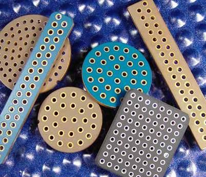
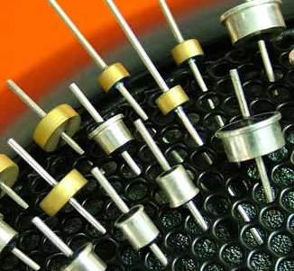
28 Introduction to Panel Mount EMI s Introduction to Panel Mount EMI s Panel Mount filters are designed to be mounted into a wall or bulkhead that is forming a Faraday cage. The body of the filter acts as the ground connection and the lead pin carries the signal through the filter. All Panel Mount filters are true feedthrough devices incorporating discoidal capacitors for the maximum performance over the widest frequency range. Performance plots to 15GHz can be supplied on demand. The range of filters have the following advantages Robust construction Feedthrough designs (no chip or leaded 2 terminal capacitors) High Voltage / High capacitance Stable and Ultra-Stable CG/NP dielectrics Circuit types include C, L-C, T and Pi as catalogue standards Multi-element s (e.g. L-C-L-C-L circuits) are also available as custom designs The Panel Mount range can be categorised into three distinct families: Family Part numbers Description Disc-on-pin filters Solder-in body filters Ø3.2 (.126) Threaded ceramic based filters 6. ± 1. (.236).25 (.1) PIN Ø.7 (.28) 9. ± 1. (.354) 3. (.118) SFSSC* SFSRC SFSTC SFSUC All other SF** part numbers All parts can be offered with additional Hi-Rel testing (for example burn-in). Please refer to factory. Resin Sealed s Construction The resin sealed panel mount filter ranges feature silver plated brass bodies and copper alloy pins. In all cases the capacitive element is a low ESR high performance discoidal ceramic multilayer device. Tin/lead metalwork plating is available as an option and tin can be considered but is not recommended due to the potential for tin whiskers. Non-standard finishes may incur additional charges or minimum order quantities. Where applicable, sealing is by high purity glob top encapsulant, heat cured. Inductors Inductors are ferrite beads. These may suffer from saturation under full operating conditions. Voltage and Current rating All voltage and current ratings are quoted over the full operating temperature range. Allowance should be made for anticipated surge currents. Any voltage spike withstand requirements should be referred to the factory as they can have a serious effect on the reliability of the device. Ø2.8 ±.1 (.11) The lowest cost option. Discoidal feedthrough capacitor mounted on a feedthrough pin. Designed to be solder mounted into panel. Exposed ceramic means care must be taken in handling and operating conditions. As above but with the added benefit of the capacitor being protected by a machined brass body and resin seal. Easier to use and offers greater protection to the ceramic component. Single or multi element filters mounted in threaded bodies and resin sealed. Most can be supplied with appropriate mounting hardware. A very wide range of options to suit most mechanical requirements. s with a dual dc/ac voltage rating are identified in the individual datasheets. Other filters may also be suitable for use under ac voltage conditions, please refer enquiries to the factory. In all cases where a filter is operated under ac conditions, current flow to ground through the capacitor and self-heating of the device will occur, dependent on the capacitance, frequency and voltage. It is the responsibility of the customer to determine if operation in application is acceptable. Safety Care should be taken not to exceed the maximum rated voltage and current for the filter. All the filters in this catalogue are designed to operate at high currents/high voltages and may be fitted with high capacitances resulting in a potential electric shock hazard. energy may be stored for some time after switch off do not handle filters without first discharging and/or checking that the stored voltage is at a low level. 26
29 Introduction to Panel Mount EMI s Insertion Loss figures Insertion loss plots and figures supplied are typical only and are measured on in small cavity closed chambers to allow measurements to 1GHz for most s. Individual performance plots can be supplied on request. All feedthrough filters display a resonance at some point in the insertion loss sweep and this will be evident in any supplied plot - the Example curves Panel Mount C Insertion Loss Loss (db) Panel Mount Pi Insertion Loss Loss (db) nF C filter 68nF C filter 33nF C filter 3.3µF C filter frequency and magnitude of these resonances varies with the design of the test chamber being used. All typical figures tabulated on the datasheets ignore these resonances. If a direct comparison test between components is required, we are happy to carry this out. All measurements are taken using a Vector Network Analyser in a 5Ω system, no load Frequency (MHz) 6.6nF Pi filter 94nF Pi filter 94nF Pi filter 6.6µF Pi filter Introduction to Panel Mount EMI s Frequency (MHz) 27
30 SFSSC CG/NP & SFSSC ØD 8. ± 1 (.315) 14. (.55) Discoidal Capacitors with Leads PIN Ød 2. (.79) Standard dimensions shown. Lead lengths can be customised - Refer to factory. 6. ± 1 (.236) Details Configuration C 1hr Point See Table Insulation Resistance (IR) 1GW or 1WF Ferrite Inductance (Typical) Not Applicable Max Soldering Temperature 25 C Temperature Rise Less than 4 C per second Soldering Time 1 seconds maximum Solder Sn62/SAC or equivalent Pin Material Copper Alloy (silver plated) Dielectric Withstand Voltage (D.W.V) Voltage D.W.V. Voltage D.W.V. 5Vdc 125Vdc 5Vdc 75Vdc 1Vdc 25Vdc 1Vdc 12Vdc 2Vdc 5Vdc 2Vdc 24Vdc 3Vdc 55Vdc 3Vdc 36Vdc C Ordering Information - SFSSC range SF S S C 5 12 M X /46 Suffix Code Cap. Diameter (D) 2.3mm (.91") 2.8mm (.11") 3mm (.118") 5mm (.197") 8.75mm (.344") Pin Diameter (d).7mm (.28").7mm (.28").7mm (.28").7mm (.28") 1.mm (.39") Tol. -2% +8% Thread Solder S = Special (no case) C = C -2%+8% up to 47pF ±2% 68pF & above Voltage (dc) in picofarads (pf) Tolerance Dielectric 5 = 5V 1 = 1V 2 = 2V 5 = 5V 1K = 1kV 2K = 2kV 3K = 3kV -2%+8% up to 47pF ±2% 68pF & above First digit is. Second and third digits are significant figures of Example: 11 = 1pF 332 = 33pF ±2% ±2% Max. 1A 1A 1A 1A 15A Voltage d.c. 5V 1V 2V 5V 5V 1V 2V 3V 5V 5V 1V 2V 3V 5V 5V 1V 2V 3V 5V 5V 1V 2V 3V 5V 1kV 2kV 3kV 1pF CG CG 15pF CG 22pF CG CG 33pF CG 47pF CG CG 68pF CG 1pF CG CG CG 15pF CG CG 22pF CG CG CG 33pF CG CG 47pF CG 68pF CG 1.nF CG 1.5nF 2.2nF 3.3nF 4.7nF 6.8nF 1nF 15nF 22nF 33nF 47nF 68nF 1nF 15nF 22nF 33nF 47nF 68nF 1.µF 1.5µF 2.2µF 3.3µF Cap Value M = ±2% Z = -2+8% C = CG/ NP X = Options include for example: change of finish / alternative voltage rating / non-standard intermediate capacitance values/test requirements. Please refer specific requests to the factory. Nuts & Washers Suffix Code = Without /66 /96 /46 /97 28
31 SFSRC CG/NP & Ø3.2 (.126) 6. ± 1. (.236).25 (.1) 9. ± 1. (.354) Ø2.8 ±.1 (.11) Details Configuration Measurement Insulation Resistance (IR) Ferrite Inductance (Typical) 1hr Point 1A 1GW or 1WF Not Applicable C SFSRC Body Flange Diameter 3.2mm (.126 ) Mounting Hole Diameter 3.mm (.118 ) 2.8mm Body Diameter Epoxy Sealed PIN Ø.7 (.28) 3. (.118) Max Soldering Temperature 25 C Temperature Rise Less than 4 C per second Soldering Time 1 seconds maximum Solder Sn62/SAC or equivalent.4g (.15oz) (-2 +8%) Dielectric Voltage.1MHz.1MHz 1MHz 1MHz 1MHz 1GHz *SFSRC51ZC 1pF SFSRC522ZC 22pF SFSRC547ZC 47pF CG/NP *SFSRC511ZC 1pF SFSRC5221ZC 22pF 5# SFSRC5471ZX 47pF *SFSRC512ZX 1.nF SFSRC5222ZX 2.2nF *SFSRC5472ZX 4.7nF *SFSRC213ZX 1nF *SFSRC1223ZX 22nF *SFSRC5473ZX 47nF # Also rated for operation at 115Vac 4Hz. Self heating will occur - evaluation in situ recommended. * Recommended values. Ordering Information - SFSRC range SF S R C Z X Dia. Solder 2.8mm C = C 5 = 5V 1 = 1V 2 = 2V 5 = 5V Voltage (dc) in picofarads (pf) Tolerance Dielectric First digit is. Second and third digits are significant figures of Example: 11 = 1pF 332 = 33pF Z = -2+8% C = CG/NP X = Nuts & Washers = Without Options include for example: change of finish / alternative voltage rating / non-standard intermediate capacitance values / test requirements. Please refer specific requests to the factory. 29
32 SFSTC CG/NP & SFSTC Ø4. (.157) 6. ± 1. (.236).5 (.2) 9. ± 1. (.354) Ø3.25 ±.1 (.128) Details Configuration C 1hr Point 1A Insulation Resistance (IR) 1GW or 1WF Ferrite Inductance (Typical) Not Applicable Body Flange Diameter 4.mm (.157 ) C PIN Ø.7 (.28) 2.8 (.11) Mounting Hole Diameter 3.5mm (.138 ) Max Soldering Temperature 25 C Temperature Rise Less than 4 C per second 3.25mm Body Diameter Epoxy Sealed Soldering Time Solder 1 seconds maximum Sn62/SAC or equivalent.4g (.15oz) (±2%) UOS Dielectric Voltage.1MHz.1MHz 1MHz 1MHz 1MHz 1GHz SFSTC51ZC 1pF -2% / +8% SFSTC515ZC 15pF -2% / +8% SFSTC522ZC 22pF -2% / +8% SFSTC533ZC 33pF -2% / +8% SFSTC547ZC 47pF -2% / +8% SFSTC568MC 68pF CG/NP *SFSTC511MC 1pF SFSTC5151MC 15pF SFSTC5221MC 22pF SFSTC5331MC 33pF SFSTC5471MC 47pF 5# SFSTC5681MC 68pF SFSTC512MX 1.nF *SFSTC5152MX 1.5nF *SFSTC5222MX 2.2nF *SFSTC5332MX 3.3nF *SFSTC5472MX 4.7nF SFSTC5682MX 6.8nF *SFSTC513MX 1nF SFSTC5153MX 15nF *SFSTC5223MX 22nF *SFSTC3333MX 33nF SFSTC2473MX 47nF SFSTC1683MX 68nF >7 SFSTC514MX 1nF >7 # Also rated for operation at 115Vac 4Hz. Self heating will occur - evaluation in situ recommended. * Recommended values. Ordering Information - SFSTC range SF S T C M X Dia. Solder 3.25mm C = C 5 = 5V 1 = 1V 2 = 2V 3 = 3V 5 = 5V Voltage (dc) in picofarads (pf) Tolerance Dielectric First digit is. Second and third digits are significant figures of Example: 11 = 1pF 332 = 33pF M = ±2% Z = -2+8% C = CG/NP X = Nuts & Washers = Without Options include for example: change of finish / alternative voltage rating / non-standard intermediate capacitance values / test requirements. Please refer specific requests to the factory. 3
33 SFSUC CG/NP & Ø6.5 (.256) 6. ± 1. (.236).5 (.2) 9. ± 1. (.354) Ø5.6 ±.1 (.22) Details Configuration C 1hr Point 1A Insulation Resistance (IR) 1GW or 1WF Ferrite Inductance (Typical) Not Applicable Body Flange Diameter 6.5mm (.256 ) C SFSUC Mounting Hole Diameter 5.8mm (.228 ) Max. Soldering Temperature 25ºC PIN Ø.7 (.28) Solder Mount EMI 3. (.118) Temperature Rise Soldering Time Solder Less than 4ºC per second 1 seconds maximum Sn62/SAC or equivalent.7g (.25oz) Dielectric Voltage (±2%) UOS.1MHz.1MHz 1MHz 1MHz 1MHz 1GHz *SFSUC51ZC 1pF -2% / +8% SFSUC515ZC 15pF -2% / +8% SFSUC522ZC 22pF -2% / +8% SFSUC533ZC 33pF -2% / +8% *SFSUC547ZC 47pF -2% / +8% *SFSUC568MC 68pF CG/NP *SFSUC511MC 1pF SFSUC5151MC 15pF *SFSUC5221MC 22pF *SFSUC5331MC 33pF *SFSUC5471MC 47pF SFSUC5681MC 68pF *SFSUC512MX 1.nF # 75 SFSUC5152MX 1.5nF *SFSUC5222MX 2.2nF SFSUC5332MX 3.3nF *SFSUC5472MX 4.7nF SFSUC5682MX 6.8nF *SFSUC513MX 1nF *SFSUC5153MX 15nF *SFSUC5223MX 22nF SFSUC5333MX 33nF *SFSUC5473MX 47nF *SFSUC5683MX 68nF >7 *SFSUC514MX 1nF >7 SFSUC5154MX 15nF >7 *SFSUC2224MX 22nF >7 SFSUC1334MX 33nF >7 25 *SFSUC1474MX 47nF >7 SFSUC5684MX 68nF >7 # Also rated for operation at 115Vac 4Hz. Self heating will occur - evaluation in situ recommended. * Recommended values. Ordering Information - SFSUC range SF S U C M X Dia. Solder 5.6mm C = C 5 = 5V 1 = 1V 2 = 2V 5 = 5V Voltage (dc) in picofarads (pf) Tolerance Dielectric First digit is. Second and third digits are significant figures of Example: 11 = 1pF 332 = 33pF M = ±2% Z = -2+8% Options include for example: change of finish / alternative voltage rating / non-standard intermediate capacitance values / test requirements. Please refer specific requests to the factory. C = CG/NP X = Nuts & Washers = Without 31
34 SFAAC CG/NP & SFAAC 4.mm (.157) 15. ± 1. (.591 ±.39) 3.2 (.126) 6. (.236) 17. ± 1. (.669 ±.39) Details Configuration C 1hr Point 1A Insulation Resistance (IR) 1GW or 1WF Ferrite Inductance (Typical) Not Applicable Head (A/F) 4mm (.157 ) C PIN Ø.7 (.28) Nut A/F Washer diameter Not Applicable Not Applicable Not Applicable 4-4 UNC Class 2A Thread 4.mm Hexagonal Head Mounting Hole Diameter Max. Panel Thickness 4-4 UNC Class 2B tapped hole Not Applicable.5g (.17oz) (±2%) UOS Dielectric Voltage.1MHz.1MHz 1MHz 1MHz 1MHz 1GHz *SFAAC51ZC 1pF -2% / +8% SFAAC515ZC 15pF -2% / +8% SFAAC522ZC 22pF -2% / +8% SFAAC533ZC 33pF -2% / +8% *SFAAC547ZC 47pF -2% / +8% CG/NP *SFAAC568MC 68pF *SFAAC511MC 1pF SFAAC5151MC 15pF *SFAAC5221MC 22pF *SFAAC5331MC 33pF *SFAAC5471MX 47pF # 75 SFAAC5681MX 68pF *SFAAC512MX 1.nF SFAAC5152MX 1.5nF *SFAAC5222MX 2.2nF SFAAC5332MX 3.3nF *SFAAC5472MX 4.7nF *SFAAC5682MX 6.8nF *SFAAC513MX 1nF *SFAAC5153MX 15nF *SFAAC5223MX 22nF SFAAC5333MX 33nF *SFAAC2473MX 47nF SFAAC2683MX 68nF >7 *SFAAC114MX 1nF >7 *SFAAC5154MX 15nF >7 # Also rated for operation at 115Vac 4Hz. Self heating will occur - evaluation in situ recommended. * Recommended values. Also available in CG/NP. Ordering Information - SFAAC range SF A A C M X O 4.mm Hex Head Thread 4-4 UNC C = C 5 = 5V 1 = 1V 2 = 2V 5 = 5V Voltage (dc) in picofarads (pf) Tolerance Dielectric Hardware First digit is. Second and third digits are significant figures of Example: 11 = 1pF 332 = 33pF M = ±2% Z = -2+8% Options include for example: change of finish / alternative voltage rating / non-standard intermediate capacitance values / test requirements. Please refer specific requests to the factory. C = CG/NP X = = Without 32
35 SFABC CG/NP & 4.mm (.157) 15. ± 1. (.591 ±.39) 3.2 (.126) 6. (.236) 17. ± 1. (.669 ±.39) Details Configuration C 1hr Point 1A Insulation Resistance (IR) 1GW or 1WF Ferrite Inductance (Typical) Not Applicable Head (A/F) 4mm (.157 ) C SFABC PIN Ø.7 (.28) Nut A/F 4.75mm (.187 ) Washer diameter 6.9mm (.272 ).3Nm (2.65lbf in) max. if using nut.15nm (1.32lbf in) max. into tapped hole 6-32 UNC Class 2A Thread 4.mm Hexagonal Head Mounting Hole Diameter 3.7mm ±.1 (.146 ±.4 ) Max. Panel Thickness 3.2mm (.126 ).6g (.2oz) (±2%) UOS *SFABC51ZC 1pF -2% / +8% Dielectric Voltage.1MHz.1MHz 1MHz 1MHz 1MHz 1GHz SFABC515ZC 15pF -2% / +8% SFABC522ZC 22pF -2% / +8% SFABC533ZC 33pF -2% / +8% *SFABC547ZC 47pF -2% / +8% CG/NP *SFABC568MC 68pF *SFABC511MC 1pF SFABC5151MC 15pF *SFABC5221MC 22pF *SFABC5331MC 33pF *SFABC5471MX 47pF # 75 SFABC5681MX 68pF *SFABC512MX 1.nF SFABC5152MX 1.5nF *SFABC5222MX 2.2nF SFABC5332MX 3.3nF *SFABC5472MX 4.7nF SFABC5682MX 6.8nF *SFABC513MX 1nF *SFABC5153MX 15nF *SFABC5223MX 22nF SFABC5333MX 33nF *SFABC2473MX 47nF SFABC2683MX 68nF >7 *SFABC214MX 1nF >7 *SFABC5154MX 15nF >7 # Also rated for operation at 115Vac 4Hz. Self heating will occur - evaluation in situ recommended. * Recommended values. Also available in CG/NP. Ordering Information - SFABC range SF A B C 5 12 M X 4.mm Hex Head Thread 6-32 UNC C = C 5 = 5V 1 = 1V 2 = 2V 5 = 5V Voltage (dc) in picofarads (pf) Tolerance Dielectric Hardware First digit is. Second and third digits are significant figures of capacitance code. zeros following Example: 11 = 1pF 332 = 33pF M = ±2% Z = -2+8% Options include for example: change of finish / alternative voltage rating / non-standard intermediate capacitance values / test requirements. Please refer specific requests to the factory. C = CG/NP X = = Without 1 = With 33
36 SFABL CG/NP & SFABL 4.mm (.157) 15. ± 1. (.591 ±.39) 3.2 (.126) 6. (.236) 17. ± 1. (.669 ±.39) Details Configuration L-C 1hr Point 1A Insulation Resistance (IR) 1GW or 1WF Ferrite Inductance (Typical) 5nH Head (A/F) 4.mm (.157 ) THREAD L-C PIN Ø.7 (.28) Nut A/F 4.75mm (.187 ) Washer diameter 6.9mm (.272 ).3Nm (2.65lbf in) max. if using nut.15nm (1.32lbf in) max. into tapped hole 6-32 UNC Class 2A Thread 4.mm Hexagonal Head Mounting Hole Diameter 3.7mm ±.1 (.146 ±.4 ) Max. Panel Thickness 3.2mm (.126 ).6g (.2oz) (±2%) UOS *SFABL51ZC 1pF -2% / +8% Dielectric Voltage.1MHz.1MHz 1MHz 1MHz 1MHz 1GHz SFABL515ZC 15pF -2% / +8% SFABL522ZC 22pF -2% / +8% SFABL533ZC 33pF -2% / +8% *SFABL547ZC 47pF -2% / +8% CG/NP *SFABL568MC 68pF *SFABL511MC 1pF SFABL5151MC 15pF *SFABL5221MC 22pF *SFABL5331MC 33pF *SFABL5471MX 47pF # 75 SFABL5681MX 68pF *SFABL512MX 1.nF SFABL5152MX 1.5nF *SFABL5222MX 2.2nF SFABL5332MX 3.3nF *SFABL5472MX 4.7nF SFABL5682MX 6.8nF *SFABL513MX 1nF *SFABL5153MX 15nF *SFABL5223MX 22nF SFABL5333MX 33nF *SFABL2473MX 47nF >7 2 5 SFABL2683MX 68nF >7 *SFABL114MX 1nF >7 *SFABL5154MX 15nF >7 # Also rated for operation at 115Vac 4Hz. Self heating will occur - evaluation in situ recommended. * Recommended values. Also available in CG/NP. Ordering Information- SFABL range SF A B L M X 4.mm Hex Head Thread 6-32 UNC L = L-C 5 = 5V 1 = 1V 2 = 2V 5 = 5V Voltage (dc) in picofarads (pf) Tolerance Dielectric Hardware First digit is. Second and third digits are significant figures of Example: 11 = 1pF 332 = 33pF M = ±2% Z = -2+8% Options include for example: change of finish / alternative voltage rating / non-standard intermediate capacitance values / test requirements. Please refer specific requests to the factory. C = CG/NP X = = Without 1 = With 34
37 SFAJC CG/NP & 4.mm (.157) 15. ± 1. (.591 ±.39) 3.2 (.126) 6. (.236) 17. ± 1. (.669 ±.39) Details Configuration C 1hr Point 1A Insulation Resistance (IR) 1GW or 1WF Ferrite Inductance (Typical) Not Applicable Head (A/F) 4.mm (.157 ) C SFAJC PIN Ø.7 (.28) Nut A/F 4.mm (.187 ) Washer diameter 6.9mm (.272 ).25Nm (2.21lbf in) max. if using nut.15nm (1.32lbf in) max. into tapped hole M3 x.5-6g Thread 4.mm Hexagonal Head Mounting Hole Diameter 3.15mm ±.1 (.124 ±.4 ) Max. Panel Thickness 3.2mm (.126 ).5g (.17oz) (±2%) UOS *SFAJC51ZC 1pF -2% / +8% Dielectric Voltage.1MHz.1MHz 1MHz 1MHz 1MHz 1GHz SFAJC515ZC 15pF -2% / +8% SFAJC522ZC 22pF -2% / +8% SFAJC533ZC 33pF -2% / +8% *SFAJC547ZC 47pF -2% / +8% CG/NP *SFAJC568MC 68pF *SFAJC511MC 1pF SFAJC5151MC 15pF *SFAJC5221MC 22pF *SFAJC5331MC 33pF *SFAJC5471MX 47pF # 75 SFAJC5681MX 68pF *SFAJC512MX 1.nF SFAJC5152MX 1.5nF *SFAJC5222MX 2.2nF SFAJC5332MX 3.3nF *SFAJC5472MX 4.7nF *SFAJC5682MX 6.8nF *SFAJC513MX 1nF *SFAJC5153MX 15nF *SFAJC5223MX 22nF SFAJC5333MX 33nF *SFAJC2473MX 47nF SFAJC2683MX 68nF >7 *SFAJC114MX 1nF >7 *SFAJC5154MX 15nF >7 # Also rated for operation at 115Vac 4Hz. Self heating will occur - evaluation in situ recommended. * Recommended values. Also available in CG/NP. Ordering Information - SFAJC range SF A J C M X 4.mm Hex Head Thread M3 C = C 5 = 5V 1 = 1V 2 = 2V 5 = 5V Voltage (dc) in picofarads (pf) Tolerance Dielectric Hardware First digit is. Second and third digits are significant figures of capacitance code. zeros following Example: 11 = 1pF 332 = 33pF M = ±2% Z = -2+8% Options include for example: change of finish / alternative voltage rating / non-standard intermediate capacitance values / test requirements. Please refer specific requests to the factory. C = CG/NP X = = Without 1 = With 35
38 SFAJL CG/NP & SFAJL 4.mm (.157) 15. ± 1. (.591 ±.39) 3.2 (.126) 6. (.236) 17. ± 1. (.669 ±.39) Details Configuration L-C 1hr Point 1A Insulation Resistance (IR) 1GW or 1WF Ferrite Inductance (Typical) 5nH Head (A/F) 4.mm (.157 ) THREAD L-C PIN Ø.7 (.28) Nut A/F 4.mm (.157 ) Washer diameter 6.9mm (.272 ).25Nm (2.21lbf in) max. if using nut.15nm (1.32lbf in) max. into tapped hole M3 x.5-6g Thread 4.mm Hexagonal Head Mounting Hole Diameter 3.15mm ±.1 (.124 ±.4 ) Max. Panel Thickness 3.2mm (.126 ).5g (.17oz) (±2%) UOS *SFAJL51ZC 1pF -2% / +8% Dielectric Voltage.1MHz.1MHz 1MHz 1MHz 1MHz 1GHz SFAJL515ZC 15pF -2% / +8% SFAJL522ZC 22pF -2% / +8% SFAJL533ZC 33pF -2% / +8% *SFAJL547ZC 47pF -2% / +8% CG/NP *SFAJL568MC 68pF *SFAJL511MC 1pF SFAJL5151MC 15pF *SFAJL5221MC 22pF *SFAJL5331MC 33pF *SFAJL5471MX 47pF # 75 SFAJL5681MX 68pF *SFAJL512MX 1.nF SFAJL5152MX 1.5nF *SFAJL5222MX 2.2nF SFAJL5332MX 3.3nF *SFAJL5472MX 4.7nF SFAJL5682MX 6.8nF *SFAJL513MX 1nF *SFAJL5153MX 15nF *SFAJL5223MX 22nF SFAJL5333MX 33nF *SFAJL2473MX 47nF >7 2 5 SFAJL2683MX 68nF >7 *SFAJL114MX 1nF >7 *SFAJL5154MX 15nF >7 # Also rated for operation at 115Vac 4Hz. Self heating will occur - evaluation in situ recommended. * Recommended values. Also available in CG/NP. Ordering Information - SFAJL range SF A J L M X 1 4.mm Hex Head Thread M3 L = L-C 5 = 5V 1 = 1V 2 = 2V 5 = 5V Voltage (dc) in picofarads (pf) Tolerance Dielectric Hardware First digit is. Second and third digits are significant figures of Example: 11 = 1pF 332 = 33pF M = ±2% Z = -2+8% Options include for example: change of finish / alternative voltage rating / non-standard intermediate capacitance values / test requirements. Please refer specific requests to the factory. C = CG/NP X = = Without 1 = With 36
39 SFAKC CG/NP & 4. A/F (.157) PIN Ø.7 (.28) M3.5 x.6-6g Thread 4.mm Hexagonal Head L1 ± 1. L2 ± (.128) A SUFFIX A L1 L2 NONE / Details Configuration C 1hr Point 1A Insulation Resistance (IR) 1GW or 1WF C Ferrite Inductance (Typical) Not Applicable Head (A/F) 4.mm (.157 ) Nut A/F 4.75mm (.187 ) Washer diameter 6.9mm (.272 ).35Nm (3.9lbf in) max. if using nut.18nm (1.59lbf in) max. into tapped hole Mounting Hole Diameter 3.7mm ±.1 (.146 ±.4 ) Max. Panel Thickness 3.25mm (.128 ).6g (.2oz) SFAKC (±2%) UOS *SFAKC51ZC 1pF -2% / +8% Dielectric Voltage.1MHz.1MHz 1MHz 1MHz 1MHz 1GHz SFAKC515ZC 15pF -2% / +8% SFAKC522ZC 22pF -2% / +8% SFAKC533ZC 33pF -2% / +8% *SFAKC547ZC 47pF -2% / +8% CG/NP *SFAKC568MC 68pF *SFAKC511MC 1pF SFAKC5151MC 15pF *SFAKC5221MC 22pF *SFAKC5331MC 33pF *SFAKC5471MX 47pF # 75 SFAKC5681MX 68pF *SFAKC512MX 1.nF SFAKC5152MX 1.5nF *SFAKC5222MX 2.2nF SFAKC5332MX 3.3nF *SFAKC5472MX 4.7nF *SFAKC5682MX 6.8nF *SFAKC513MX 1nF *SFAKC5153MX 15nF *SFAKC5223MX 22nF SFAKC5333MX 33nF *SFAKC2473MX 47nF SFAKC2683MX 68nF >7 *SFAKC114MX 1nF >7 *SFAKC5154MX 15nF >7 # Also rated for operation at 115Vac 4Hz. Self heating will occur - evaluation in situ recommended. * Recommended values. Also available in CG/NP. Ordering Information - SFAKC range SF A K C 5 68 M C /22 4.mm Hex Head Thread Voltage (dc) M3.5 C = C 5 = 5V 1 = 1V 2 = 2V 5 = 5V in picofarads (pf) First digit is. Second and third digits are significant figures of Example: 11 = 1pF 332 = 33pF Tolerance Dielectric Hardware Suffix M = ±2% Z = -2+8% C = CG/NP X = = Without 1 = With /22= short thread & lead length (see drawing) Options include for example: change of finish / alternative voltage rating / non-standard intermediate capacitance values / test requirements. Please refer specific requests to the factory. 37
40 SFAKL CG/NP & SFAKL 4.mm (.157) 15. ± 1. (.591 ±.39) 3.2 (.126) 6. (.236) 17. ± 1. (.669 ±.39) Details Configuration L-C 1hr Point 1A Insulation Resistance (IR) 1GW or 1WF Ferrite Inductance (Typical) 5nH Head (A/F) 4.mm (.157 ) THREAD L-C PIN Ø.7 (.28) Nut A/F 4.75mm (.187 ) Washer diameter 6.9mm (.272 ).35Nm (3.9lbf in) max. if using nut.18nm (1.59lbf in) max. into tapped hole M3.5 x.6-6g Thread 4.mm Hexagonal Head Mounting Hole Diameter 3.7mm ±.1 (.146 ±.4 ) Max. Panel Thickness 3.25mm (.128 ).6g (.2oz) (±2%) UOS *SFAKL51ZC 1pF -2% / +8% Dielectric Voltage.1MHz.1MHz 1MHz 1MHz 1MHz 1GHz SFAKL515ZC 15pF -2% / +8% SFAKL522ZC 22pF -2% / +8% SFAKL533ZC 33pF -2% / +8% *SFAKL547ZC 47pF -2% / +8% CG/NP *SFAKL568MC 68pF *SFAKL511MC 1pF SFAKL5151MC 15pF *SFAKL5221MC 22pF *SFAKL5331MC 33pF *SFAKL5471MX 47pF # 75 SFAKL5681MX 68pF *SFAKL512MX 1.nF SFAKL5152MX 1.5nF *SFAKL5222MX 2.2nF SFAKL5332MX 3.3nF *SFAKL5472MX 4.7nF SFAKL5682MX 6.8nF *SFAKL513MX 1nF *SFAKL5153MX 15nF *SFAKL5223MX 22nF SFAKL5333MX 33nF *SFAKL2473MX 47nF >7 2 5 SFAKL2683MX 68nF >7 SFAKL114MX 1nF >7 SFAKL5154MX 15nF >7 # Also rated for operation at 115Vac 4Hz. Self heating will occur - evaluation in situ recommended. * Recommended values. Also available in CG/NP. Ordering Information - SFAKL range SF A K L 1 14 M X 1 4.mm Hex Head Thread M3.5 L = L-C 5 = 5V 1 = 1V 2 = 2V 5 = 5V Voltage (dc) in picofarads (pf) Tolerance Dielectric Hardware First digit is. Second and third digits are significant figures of Example: 11 = 1pF 332 = 33pF M = ±2% Z = -2+8% Options include for example: change of finish / alternative voltage rating / non-standard intermediate capacitance values / test requirements. Please refer specific requests to the factory. C = CG/NP X = = Without 1 = With 38
41 SFAKT CG/NP & 4. A/F (.157) M3.5 x.6-6g Thread 4.mm Hexagonal Head 16. ± ± (.256) (.157) PIN Ø.7 (.28).9 UNCUT (.35) Details Configuration T 1hr Point 1A Insulation Resistance (IR) 1GW or 1WF T Ferrite Inductance (Typical) 1nH Head (A/F) 4.mm (.157 ) Nut A/F 4.75mm (.187 ) Washer diameter 6.9mm (.272 ).35Nm (3.9lbf in) max. if using nut.18nm (1.59lbf in) max. into tapped hole Mounting Hole Diameter 3.7mm ±.1 (.146 ±.4 ) Max. Panel Thickness 3.25mm (.128 ).6g (.2oz) SFAKT (±2%) UOS *SFAKT51ZC 1pF -2% / +8% Dielectric Voltage.1MHz.1MHz 1MHz 1MHz 1MHz 1GHz SFAKT515ZC 15pF -2% / +8% SFAKT522ZC 22pF -2% / +8% SFAKT533ZC 33pF -2% / +8% *SFAKT547ZC 47pF -2% / +8% CG/NP *SFAKT568MC 68pF *SFAKT511MC 1pF SFAKT5151MC 15pF *SFAKT5221MC 22pF *SFAKT5331MC 33pF *SFAKT5471MX 47pF # 75 SFAKT5681MX 68pF *SFAKT512MX 1.nF SFAKT5152MX 1.5nF *SFAKT5222MX 2.2nF SFAKT5332MX 3.3nF *SFAKT5472MX 4.7nF SFAKT5682MX 6.8nF *SFAKT513MX 1nF *SFAKT5153MX 15nF *SFAKT5223MX 22nF SFAKT5333MX 33nF >7 *SFAKT2473MX 47nF >7 2 5 SFAKT2683MX 68nF >7 *SFAKT114MX 1nF >7 *SFAKT5154MX 15nF >7 # Also rated for operation at 115Vac 4Hz. Self heating will occur - evaluation in situ recommended. * Recommended values. Also available in CG/NP. Ordering Information - SFAKT range SF A K T 5 12 M X Thread Voltage (dc) in picofarads (pf) Tolerance Dielectric Hardware 4.mm Hex Head M3.5 T = T 5 = 5V 1 = 1V 2 = 2V 5 = 5V First digit is. Second and third digits are significant figures of Example: 11 = 1pF 332 = 33pF M = ±2% Z = -2+8% C = CG/NP X = = Without 1 = With Options include for example: change of finish / alternative voltage rating / non-standard intermediate capacitance values / test requirements. Please refer specific requests to the factory. 39
42 SFBCC CG/NP & SFBCC 4.75mm (.157) 15. ± 1. (.591 ±.39) 3.2 (.126) 6. (.236) 17. ± 1. (.669 ±.39) Details Configuration C 1hr Point 1A Insulation Resistance (IR) 1GW or 1WF Ferrite Inductance (Typical) Not Applicable Head (A/F) 4.75mm (.187 ) C PIN Ø.7 (.28) Nut A/F 6.35mm (.25 ) Washer diameter 8mm (.315 ).5Nm (4.42lbf in) max. if using nut.25nm (2.21lbf in) max. into tapped hole 8-32 UNC Class 2A Thread 4.75mm Hexagonal Head Mounting Hole Diameter 4.4mm ±.1 (.173 ±.4 ) Max. Panel Thickness 2.9mm (.114 ) 1.2g (.4oz) (±2%) UOS *SFBCC51ZC 1pF -2% / +8% Dielectric Voltage.1MHz.1MHz 1MHz 1MHz 1MHz 1GHz SFBCC515ZC 15pF -2% / +8% SFBCC522ZC 22pF -2% / +8% SFBCC533ZC 33pF -2% / +8% *SFBCC547ZC 47pF -2% / +8% CG/NP *SFBCC568MC 68pF *SFBCC511MC 1pF SFBCC5151MC 15pF *SFBCC5221MC 22pF *SFBCC5331MC 33pF *SFBCC5471MX 47pF # 75 SFBCC5681MX 68pF *SFBCC512MX 1.nF SFBCC5152MX 1.5nF *SFBCC5222MX 2.2nF SFBCC5332MX 3.3nF *SFBCC5472MX 4.7nF SFBCC5682MX 6.8nF *SFBCC513MX 1nF *SFBCC5153MX 15nF *SFBCC5223MX 22nF SFBCC5333MX 33nF *SFBCC2473MX 47nF SFBCC2683MX 68nF >7 *SFBCC114MX 1nF >7 *SFBCC5154MX 15nF >7 # Also rated for operation at 115Vac 4Hz. Self heating will occur - evaluation in situ recommended. * Recommended values. Also available in CG/NP. Ordering Information - SFBCC range SF B C C 5 12 M X 4.75mm Hex Head Thread 8-32 UNC C = C 5 = 5V 1 = 1V 2 = 2V 5 = 5V Voltage (dc) in picofarads (pf) Tolerance Dielectric Hardware First digit is. Second and third digits are significant figures of Example: 11 = 1pF 332 = 33pF M = ±2% Z = -2+8% C = CG/NP X = = Without 1 = With Options include for example: change of finish / alternative voltage rating / non-standard intermediate capacitance values / test requirements. Please refer specific requests to the factory. 4
43 SFBCL CG/NP & 4.75 A/F (.187) 15. ± 1. (.591 ±.39) 3.2 (.126) 6. (.236) 17. ± 1. (.669 ±.39) Details Configuration L-C 1hr Point 1A Insulation Resistance (IR) 1GW or 1WF Ferrite Inductance (Typical) 5nH Head (A/F) 4.75mm (.187 ) THREAD L-C SFBCL PIN Ø.7 (.28) Nut A/F 6.35mm (.25 ) Washer diameter 8mm (.315 ).5Nm (4.42lbf in) max. if using nut.25nm (2.21lbf in) max. into tapped hole 8-32 UNC Class 2A Thread 4.75mm Hexagonal Head Mounting Hole Diameter 4.4mm ±.1 (.173 ±.4 ) Max. Panel Thickness 2.9mm (.114 ) 1.2g (.4oz) (±2%) UOS *SFBCL51ZC 1pF -2% / +8% Dielectric Voltage.1MHz.1MHz 1MHz 1MHz 1MHz 1GHz SFBCL515ZC 15pF -2% / +8% SFBCL522ZC 22pF -2% / +8% SFBCL533ZC 33pF -2% / +8% *SFBCL547ZC 47pF -2% / +8% CG/NP *SFBCL568MC 68pF *SFBCL511MC 1pF SFBCL5151MC 15pF *SFBCL5221MC 22pF *SFBCL5331MC 33pF *SFBCL5471MX 47pF # 75 SFBCL5681MX 68pF *SFBCL512MX 1.nF SFBCL5152MX 1.5nF *SFBCL5222MX 2.2nF SFBCL5332MX 3.3nF *SFBCL5472MX 4.7nF SFBCL5682MX 6.8nF *SFBCL513MX 1nF *SFBCL5153MX 15nF *SFBCL5223MX 22nF SFBCL5333MX 33nF *SFBCL2473MX 47nF >7 2 5 SFBCL2683MX 68nF >7 *SFBCL114MX 1nF >7 *SFBCL5154MX 15nF >7 # Also rated for operation at 115Vac 4Hz. Self heating will occur - evaluation in situ recommended. * Recommended values. Also available in CG/NP. Ordering Information - SFBCL range SF B C L 5 12 M X 4.75mm Hex Head Thread Voltage (dc) 8-32 UNC L = L-C 5 = 5V 1 = 1V 2 = 2V 5 = 5V in picofarads (pf) First digit is. Second and third digits are significant figures of Example: 11 = 1pF 332 = 33pF Tolerance Dielectric Hardware M = ±2% Z = -2+8% Options include for example: change of finish / alternative voltage rating / non-standard intermediate capacitance values / test requirements. Please refer specific requests to the factory. C = CG/NP X = = Without 1 = With 41
44 SFBCP CG/NP & SFBCP 4.75 A/F (.187) 8-32 UNC Class 2A Thread 4.75mm Hexagonal Head ± ± 1. (.561±.39) (.699±.39) PIN Ø.7 (.28) (.126) (.236) Details Configuration Pi 1hr Point 1A Insulation Resistance (IR) 1GW or 1WF Pi Ferrite Inductance (Typical) 75nH Head (A/F) 4.75mm (.187 ) Nut A/F 6.35mm (.25 ) Washer diameter 9.4mm (.37 ).5Nm (4.42lbf in) max. if using nut.25nm (2.21lbf in) max. into tapped hole Mounting Hole Diameter 4.4mm ±.1 (.173 ±.4 ) Max. Panel Thickness 2.9mm (.114 ) 1.2g (.4oz) *SFBCP52ZC -2/+8% 2pF Dielectric Voltage.1MHz.1MHz 1MHz 1MHz 1MHz 1GHz SFBCP544ZC 44pF SFBCP594ZC 94pF CG/NP *SFBCP521ZC 2pF SFBCP5441ZC 44pF 5# SFBCP5941ZX 94pF *SFBCP522ZX 2nF SFBCP5442ZX 4.4nF >7 *SFBCP5942ZX 9.4nF >7 *SFBCP223ZX 2nF >7 *SFBCP1443ZX 44nF >7 >7 *SFBCP5943ZX 94nF >7 >7 # Also rated for operation at 115Vac 4Hz. Self heating will occur - evaluation in situ recommended. * Recommended values. Also available in CG/NP. Ordering Information - SFBCP range SF B C P Z X 4.75mm Hex Head Thread 8-32 UNC P = Pi 5 = 5V 1 = 1V 2 = 2V 5 = 5V Voltage (dc) in picofarads (pf) Tolerance Dielectric Hardware First digit is. Second and third digits are significant figures of Example: 21 = 2pF 943 = 94pF Z = -2+8% C = CG/NP X = = Without 1 = With Options include for example: change of finish / alternative voltage rating / non-standard intermediate capacitance values / test requirements. Please refer specific requests to the factory. 42
45 SFBDC CG/NP & Ø A/F (.187) 15. ± ± 1. (.591 ±.39) (.699 ±.39) (.157) (.315) Details Configuration C 1hr Point 1A Insulation Resistance (IR) 1GW or 1WF Ferrite Inductance (Typical) Not Applicable Body Flange Diameter 6.35mm (.25 ) C SFBDC Head (A/F) 4.75mm (.187 ) PIN Ø.7 (.28) Nut A/F 7.92mm (.312 ) Washer diameter 9.4mm (.37 ).6Nm (5.31lbf in) max. if using nut.3nm (2.65lbf in) max. into tapped hole UNEF Class 2A Thread 4.75mm Hexagonal Head/6.35mm flange Mounting Hole Diameter 5.7mm ±.1 (.224 ±.4 ) Max. Panel Thickness 4.9mm (.193 ) 1.5g (.5oz) (±2%) UOS *SFBDC51ZC 1pF -2% / +8% Dielectric Voltage.1MHz.1MHz 1MHz 1MHz 1MHz 1GHz SFBDC515ZC 15pF -2% / +8% SFBDC522ZC 22pF -2% / +8% SFBDC533ZC 33pF -2% / +8% *SFBDC547ZC 47pF -2% / +8% CG/NP *SFBDC568MC 68pF *SFBDC511MC 1pF SFBDC5151MC 15pF *SFBDC5221MC 22pF *SFBDC5331MC 33pF *SFBDC5471MX 47pF # 75 SFBDC5681MX 68pF *SFBDC512MX 1.nF SFBDC5152MX 1.5nF *SFBDC5222MX 2.2nF SFBDC5332MX 3.3nF *SFBDC5472MX 4.7nF SFBDC5682MX 6.8nF *SFBDC513MX 1nF *SFBDC5153MX 15nF *SFBDC5223MX 22nF SFBDC5333MX 33nF *SFBDC2473MX 47nF SFBDC2683MX 68nF >7 *SFBDC114MX 1nF >7 *SFBDC5154MX 15nF >7 # Also rated for operation at 115Vac 4Hz. Self heating will occur - evaluation in situ recommended. * Recommended values. Also available in CG/NP. Ordering Information - SFBDC range SF B D C 5 11 M C 4.75mm Hex Head Thread UNEF C = C Voltage (dc) 5 = 5V 1 = 1V 2 = 2V 5 = 5V in picofarads (pf) First digit is. Second and third digits are significant figures of Example: 11 = 1pF 332 = 33pF Tolerance Dielectric Hardware M = ±2% Z = -2+8% C = CG/NP X = = Without 1 = With Options include for example: change of finish / alternative voltage rating / non-standard intermediate capacitance values / test requirements. Please refer specific requests to the factory. 43
46 SFBDL CG/NP & SFBDL Ø A/F (.187) 15. ± ± 1. (.591 ±.39) (.699 ±.39) PIN Ø.7 (.28) (.157) (.315) UNEF Class 2A Thread 4.75mm Hexagonal Head/6.35mm flange Details Configuration L-C 1hr Point 1A THREAD Insulation Resistance (IR) 1GW or 1WF L-C Ferrite Inductance (Typical) 5nH Body Flange Diameter 6.35mm (.25 ) Head (A/F) 4.75mm (.187 ) Nut A/F 7.92mm (.312 ) Washer diameter 9.4mm (.37 ).6Nm (5.31lbf in) max. if using nut.3nm (2.65lbf in) max. into tapped hole Mounting Hole Diameter 5.7mm ±.1 (.224 ±.4 ) Max. Panel Thickness 4.9mm (.193 ) 1.5g (.5oz) Dielectric Voltage (±2%) UOS.1MHz.1MHz 1MHz 1MHz 1MHz 1GHz *SFBDL51ZC 1pF -2% / +8% SFBDL515ZC 15pF -2% / +8% SFBDL522ZC 22pF -2% / +8% SFBDL533ZC 33pF -2% / +8% *SFBDL547ZC 47pF -2% / +8% CG/NP *SFBDL568MC 68pF *SFBDL511MC 1pF SFBDL5151MC 15pF *SFBDL5221MC 22pF *SFBDL5331MC 33pF *SFBDL5471MX 47pF # 75 SFBDL5681MX 68pF *SFBDL512MX 1.nF SFBDL5152MX 1.5nF *SFBDL5222MX 2.2nF SFBDL5332MX 3.3nF *SFBDL5472MX 4.7nF SFBDL5682MX 6.8nF *SFBDL513MX 1nF *SFBDL5153MX 15nF *SFBDL5223MX 22nF SFBDL5333MX 33nF *SFBDL2473MX 47nF >7 2 5 SFBDL2683MX 68nF >7 *SFBDL114MX 1nF >7 *SFBDL5154MX 15nF >7 # Also rated for operation at 115Vac 4Hz. Self heating will occur - evaluation in situ recommended. * Recommended values. Also available in CG/NP. Ordering Information - SFBDL range SF B D L 5 12 M X 4.75mm Hex Head Thread UNEF L = L-C Voltage (dc) in picofarads (pf) Tolerance Dielectric Hardware 5 = 5V 1 = 1V 2 = 2V 5 = 5V First digit is. Second and third digits are significant figures of Example: 11 = 1pF 332 = 33pF M = ±2% Z = -2+8% C = CG/NP X = = Without 1 = With Options include for example: change of finish / alternative voltage rating / non-standard intermediate capacitance values / test requirements. Please refer specific requests to the factory. 44
47 SFBDP CG/NP & Ø A/F (.187) 15. ± ± 1. (.591 ±.39) (.699 ±.39) PIN Ø.7 (.28) (.157) (.315) UNEF Class 2A Thread 4.75mm Hexagonal Head/6.35mm flange Details Configuration Pi 1hr Point 1A Insulation Resistance (IR) 1GW or 1WF Pi Ferrite Inductance (Typical) 25nH Body Flange Diameter 6.35mm (.25 ) Head (A/F) 4.75mm (.187 ) Nut A/F 7.92mm (.312 ) Washer diameter 9.4mm (.37 ).6Nm (5.31lbf in) max. if using nut.3nm (2.65lbf in) max. into tapped hole Mounting Hole Diameter 5.7mm ±.1 (.224 ±.4 ) Max. Panel Thickness 4.9mm (.193 ) 1.5g (.5oz) SFBDP (±2%) UOS *SFBDP52ZC 2pF -2% / +8% Dielectric Voltage.1MHz.1MHz 1MHz 1MHz 1MHz 1GHz SFBDP53ZC 3pF -2% / +8% SFBDP544ZC 44pF -2% / +8% SFBDP566ZC 66pF -2% / +8% *SFBDP594ZC 94pF -2% / +8% CG/NP *SFBDP5136PMC 136pF *SFBDP521MC 2pF SFBDP531MC 3pF *SFBDP5441MC 44pF *SFBDP5661MC 66pF *SFBDP5941MX 94pF # 75 SFBDP51N36MX 1.36nF >7 *SFBDP522MX 2nF >7 SFBDP532MX 3nF >7 *SFBDP5442MX 4.4nF >7 SFBDP5662MX 6.6nF >7 *SFBDP5942MX 9.4nF >7 SFBDP513N6MX 13.6nF >7 >7 *SFBDP523MX 2nF >7 >7 *SFBDP533MX 3nF >7 >7 *SFBDP5443MX 44nF >7 >7 SFBDP5663MX 66nF >7 >7 *SFBDP2943MX 94nF >7 >7 2 5 SFBDP2136NMX 136nF >7 >7 >7 *SFBDP124MX 2nF >7 >7 >7 *SFBDP534MX 3nF >7 >7 >7 # Also rated for operation at 115Vac 4Hz. Self heating will occur - evaluation in situ recommended. * Recommended values. Also available in CG/NP. Ordering Information - SFBDP range SF B D P M X 4.75mm Hex Head Thread UNEF P = Pi Voltage (dc) 5 = 5V 1 = 1V 2 = 2V 5 = 5V in picofarads (pf) First digit is. Second and third digits are significant figures of Example: 21 = 2pF 943 = 94pF Tolerance Dielectric Hardware M = ±2% Z = -2+8% C = CG/NP X = = Without 1 = With Options include for example: change of finish / alternative voltage rating / non-standard intermediate capacitance values / test requirements. Please refer specific requests to the factory. 45
48 SFBDT CG/NP & SFBDT Ø A/F (.187) 15. ± ± 1. (.591 ±.39) (.699 ±.39) PIN Ø.7 (.28) (.157) (.315) UNEF Class 2A Thread 4.75mm Hexagonal Head/6.35mm flange Details Configuration T 1hr Point 1A Insulation Resistance (IR) 1GW or 1WF T Ferrite Inductance (Typical) 45nH Body Flange Diameter 6.35mm (.25 ) Head (A/F) 4.75mm (.187 ) Nut A/F 7.92mm (.312 ) Washer diameter 9.4mm (.37 ).6Nm (5.31lbf in) max. if using nut.3nm (2.65lbf in) max. into tapped hole Mounting Hole Diameter 5.7mm ±.1 (.224 ±.4 ) Max. Panel Thickness 4.9mm (.193 ) 1.5g (.5oz) Dielectric Voltage (±2%) UOS.1MHz.1MHz 1MHz 1MHz 1MHz 1GHz *SFBDT51ZC 1pF -2% / +8% SFBDT515ZC 15pF -2% / +8% SFBDT522ZC 22pF -2% / +8% SFBDT533ZC 33pF -2% / +8% *SFBDT547ZC 47pF -2% / +8% CG/NP *SFBDT568MC 68pF *SFBDT511MC 1pF SFBDT5151MC 15pF *SFBDT5221MC 22pF *SFBDT5331MC 33pF *SFBDT5471MX 47pF # 75 SFBDT5681MX 68pF *SFBDT512MX 1.nF SFBDT5152MX 1.5nF *SFBDT5222MX 2.2nF SFBDT5332MX 3.3nF *SFBDT5472MX 4.7nF SFBDT5682MX 6.8nF *SFBDT513MX 1nF *SFBDT5153MX 15nF *SFBDT5223MX 22nF SFBDT5333MX 33nF >7 *SFBDT2473MX 47nF >7 2 5 SFBDT2683MX 68nF >7 *SFBDT114MX 1nF >7 *SFBDT5154MX 15nF >7 # Also rated for operation at 115Vac 4Hz. Self heating will occur - evaluation in situ recommended. * Recommended values. Also available in CG/NP. Ordering Information - SFBDT range SF B D T 5 12 M X 4.75mm Hex Head Thread UNEF T = T Voltage (dc) in picofarads (pf) Tolerance Dielectric Hardware 5 = 5V 1 = 1V 2 = 2V 5 = 5V First digit is. Second and third digits are significant figures of Example: 11 = 1pF 332 = 33pF M = ±2% Z = -2+8% C = CG/NP X = = Without 1 = With Options include for example: change of finish / alternative voltage rating / non-standard intermediate capacitance values / test requirements. Please refer specific requests to the factory. 46
49 SFBLC CG/NP & 4.75 A/F (.187) M4 x.7-6g Thread 4.75mm Hexagonal Head ± ± 1. (.561 ±.39) (.699 ±.39) PIN Ø.7 (.28) (.128) (.236) Details Configuration C 1hr Point 1A Insulation Resistance (IR) 1GW or 1WF C Ferrite Inductance (Typical) N/A Head (A/F) 4.75mm (.187 ) Nut A/F 6.35mm (.25 ) Washer diameter 8mm (.315 ).5Nm (4.42bf in) max. if using nut.25nm (2.41lbf in) max. into tapped hole Mounting Hole Diameter 4.2mm ±.1 (.165 ±.4 ) Max. Panel Thickness 2.9mm (.114 ) 1.2g (.4oz) SFBLC Dielectric Voltage (±2%) UOS.1MHz.1MHz 1MHz 1MHz 1MHz 1GHz *SFBLC51ZC 1pF -2% / +8% SFBLC515ZC 15pF -2% / +8% SFBLC522ZC 22pF -2% / +8% SFBLC533ZC 33pF -2% / +8% *SFBLC547ZC 47pF -2% / +8% CG/NP *SFBLC568MC 68pF *SFBLC511MC 1pF SFBLC5151MC 15pF *SFBLC5221MC 22pF *SFBLC5331MC 33pF *SFBLC5471MX 47pF # 75 SFBLC5681MX 68pF *SFBLC512MX 1.nF SFBLC5152MX 1.5nF *SFBLC5222MX 2.2nF SFBLC5332MX 3.3nF *SFBLC5472MX 4.7nF SFBLC5682MX 6.8nF *SFBLC513MX 1nF *SFBLC5153MX 15nF *SFBLC5223MX 22nF SFBLC5333MX 33nF *SFBLC2473MX 47nF SFBLC2683MX 68nF >7 *SFBLC114MX 1nF >7 *SFBLC5154MX 15nF >7 # Also rated for operation at 115Vac 4Hz. Self heating will occur - evaluation in situ recommended. * Recommended values. Also available in CG/NP. Ordering Information - SFBLC range SF B L C 5 12 M X 4.75mm Hex Head Thread M4 C = C 5 = 5V 1 = 1V 2 = 2V 5 = 5V Voltage (dc) in picofarads (pf) Tolerance Dielectric Hardware First digit is. Second and third digits are significant figures of Example: 11 = 1pF 332 = 33pF M = ±2% Z = -2+8% C = CG/NP X = = Without 1 = With Options include for example: change of finish / alternative voltage rating / non-standard intermediate capacitance values / test requirements. Please refer specific requests to the factory. 47
50 SFBLL CG/NP & SFBLL 4.75mm (.157) 15. ± 1. (.591 ±.39) 3.2 (.126) 6. (.236) 17. ± 1. (.669 ±.39) Details Configuration L-C 1hr Point 1A Insulation Resistance (IR) 1GW or 1WF Ferrite Inductance (Typical) 5nH Body Flange Diameter 4.75mm (.187 ) THREAD L-C Head (A/F) 6.mm (.236 ) PIN Ø.7 (.28) Nut A/F 8.mm (.315 ).5Nm (4.42lbf in) max. if using nut.25nm (2.21lbf in) max. into tapped hole M4 x.7-6g Thread 4.75mm Hexagonal Head Mounting Hole Diameter 4.2mm ±.1 (.165 ±.4 ) Max. Panel Thickness 2.9mm (.114 ) 1.2g (.4oz) Dielectric Voltage (±2%) UOS.1MHz.1MHz 1MHz 1MHz 1MHz 1GHz *SFBLL51ZC 1pF -2% / +8% SFBLL515ZC 15pF -2% / +8% SFBLL522ZC 22pF -2% / +8% SFBLL533ZC 33pF -2% / +8% *SFBLL547ZC 47pF -2% / +8% CG/NP *SFBLL568MC 68pF *SFBLL511MC 1pF SFBLL5151MC 15pF *SFBLL5221MC 22pF *SFBLL5331MC 33pF *SFBLL5471MX 47pF # 75 SFBLL5681MX 68pF *SFBLL512MX 1.nF SFBLL5152MX 1.5nF *SFBLL5222MX 2.2nF SFBLL5332MX 3.3nF *SFBLL5472MX 4.7nF SFBLL5682MX 6.8nF *SFBLL513MX 1nF *SFBLL5153MX 15nF *SFBLL5223MX 22nF SFBLL5333MX 33nF *SFBLL2473MX 47nF >7 2 5 SFBLL2683MX 68nF >7 *SFBLL114MX 1nF >7 *SFBLL5154MX 15nF >7 # Also rated for operation at 115Vac 4Hz. Self heating will occur - evaluation in situ recommended. * Recommended values. Also available in CG/NP. Ordering Information - SFBLL range SF B L L 5 12 M X Thread Voltage (dc) in picofarads (pf) Tolerance Dielectric Nuts & Washers 4.75mm Hex Head M4 L = L-C 5 = 5V 1 = 1V 2 = 2V 5 = 5V First digit is. Second and third digits are significant figures of Example: 11 = 1pF 332 = 33pF M = ±2% Z = -2+8% C = CG/NP X = = Without 1 = With Options include for example: change of finish / alternative voltage rating / non-standard intermediate capacitance values / test requirements. Please refer specific requests to the factory. 48
51 SFBLP CG/NP & 4.75 A/F (.187) M4 x.7-6g Thread 4.75mm Hexagonal Head ± ± 1. (.561 ±.39) (.699 ±.39) PIN Ø.7 (.28) (.128) (.236) Details Configuration Pi 1hr Point 1A Insulation Resistance (IR) 1GW or 1WF Pi Ferrite Inductance (Typical) 75nH Head (A/F) 4.75mm (.187 ) Nut A/F 6.mm (.236 ) Washer diameter 7.9mm (.311 ).5Nm (4.42lbf in) max. if using nut.25nm (2.21lbf in) max. into tapped hole Mounting Hole Diameter 4.2mm ±.1 (.165 ±.4 ) Max. Panel Thickness 2.9mm (.114 ) 1.2g (.4oz) SFBLP Dielectric Voltage (-2%+8%).1MHz.1MHz 1MHz 1MHz 1MHz 1GHz *SFBLP52ZC 2pF SFBLP544ZC 44pF SFBLP594ZC 94pF CG/NP *SFBLP521ZC 2pF SFBLP5441ZC 44pF 5# SFBLP5941ZX 94pF *SFBLP522ZX 2nF SFBLP5442ZX 4.4nF >7 *SFBLP5942ZX 9.4nF >7 *SFBLP223ZX 2nF >7 *SFBLP1443ZX 44nF >7 >7 *SFBLP5943ZX 94nF >7 >7 # Also rated for operation at 115Vac 4Hz. Self heating will occur - evaluation in situ recommended. * Recommended values. Also available in CG/NP. Ordering Information - SFBLP range SF B L P Z X Thread Voltage (dc) in picofarads (pf) Tolerance Dielectric Nuts & Washers 4.75mm Hex Head M4 P = Pi 5 = 5V 1 = 1V 2 = 2V 5 = 5V First digit is. Second and third digits are significant figures of Example: 21 = 2pF 943 = 94pF Z = -2+8% C = CG/NP X = = Without 1 = With Options include for example: change of finish / alternative voltage rating / non-standard intermediate capacitance values / test requirements. Please refer specific requests to the factory. 49
52 SFBMC CG/NP & SFBMC Ø A/F (.187) 15. ± ± 1. (.591 ±.39) (.699 ±.39) PIN Ø.7 (.28) (.157) (.315) M5 x.8-6g Thread 4.75mm Hexagonal Head/6.35mm flange Details Configuration C 1hr Point 1A Insulation Resistance (IR) 1GW or 1WF C Ferrite Inductance (Typical) Not Applicable Body Flange Diameter 6.35mm (.25 ) Head (A/F) 4.75mm (.187 ) Nut A/F 6.mm (.236 ) Washer Diameter 9.1mm (.358 ).6Nm (5.31lbf in) max. if using nut.3nm (2.65lbf in) max. into tapped hole Mounting Hole Diameter 5.2mm ±.1 (.25 ±.4 ) Max. Panel Thickness 4.9mm (.193 ) 1.5g (.5oz) Dielectric Voltage (±2%) UOS.1MHz.1MHz 1MHz 1MHz 1MHz 1GHz *SFBMC51ZC 1pF -2% / +8% SFBMC515ZC 15pF -2% / +8% SFBMC522ZC 22pF -2% / +8% SFBMC533ZC 33pF -2% / +8% *SFBMC547ZC 47pF -2% / +8% CG/NP *SFBMC568MC 68pF *SFBMC511MC 1pF SFBMC5151MC 15pF *SFBMC5221MC 22pF *SFBMC5331MC 33pF *SFBMC5471MX 47pF # 75 SFBMC5681MX 68pF *SFBMC512MX 1.nF SFBMC5152MX 1.5nF *SFBMC5222MX 2.2nF SFBMC5332MX 3.3nF *SFBMC5472MX 4.7nF SFBMC5682MX 6.8nF *SFBMC513MX 1nF *SFBMC5153MX 15nF *SFBMC5223MX 22nF SFBMC5333MX 33nF *SFBMC2473MX 47nF SFBMC2683MX 68nF >7 *SFBMC114MX 1nF >7 *SFBMC5154MX 15nF >7 # Also rated for operation at 115Vac 4Hz. Self heating will occur - evaluation in situ recommended. * Recommended values. Also available in CG/NP. Ordering Information - SFBMC range SF B M C 5 12 M X Thread Voltage (dc) in picofarads (pf) Tolerance Dielectric Nuts & Washers 4.75mm Hex Head M5 C = C 5 = 5V 1 = 1V 2 = 2V 5 = 5V First digit is. Second and third digits are significant figures of Example: 11 = 1pF 332 = 33pF M = ±2% Z = -2+8% C = CG/NP X = = Without 1 = With Options include for example: change of finish / alternative voltage rating / non-standard intermediate capacitance values / test requirements. Please refer specific requests to the factory. 5
53 SFBML CG/NP & Ø A/F (.187) 15. ± ± 1. (.591 ±.39) (.699 ±.39) PIN Ø.7 (.28) (.157) (.315) M5 x.8-6g Thread 4.75mm Hexagonal Head/6.35mm flange Details Configuration L-C 1hr Point 1A THREAD Insulation Resistance (IR) 1GW or 1WF L-C Ferrite Inductance (Typical) 5nH Body Flange Diameter 6.35mm (.25 ) Head (A/F) 4.75mm (.187 ) Nut A/F 6.mm (.236 ) Washer diameter 9.1mm (.358 ).6Nm (5.31lbf in) max. if using nut.3nm (2.65lbf in) max. into tapped hole Mounting Hole Diameter 5.2mm ±.1 (.25 ±.4 ) Max. Panel Thickness 4.9mm (.193 ) 1.5g (.5oz) SFBML Dielectric Voltage (±2%) UOS.1MHz.1MHz 1MHz 1MHz 1MHz 1GHz *SFBML51ZC 1pF -2% / +8% SFBML515ZC 15pF -2% / +8% SFBML522ZC 22pF -2% / +8% SFBML533ZC 33pF -2% / +8% *SFBML547ZC 47pF -2% / +8% CG/NP *SFBML568MC 68pF *SFBML511MC 1pF SFBML5151MC 15pF *SFBML5221MC 22pF *SFBML5331MC 33pF *SFBML5471MX 47pF # 75 SFBML5681MX 68pF *SFBML512MX 1.nF SFBML5152MX 1.5nF *SFBML5222MX 2.2nF SFBML5332MX 3.3nF *SFBML5472MX 4.7nF SFBML5682MX 6.8nF *SFBML513MX 1nF *SFBML5153MX 15nF *SFBML5223MX 22nF SFBML5333MX 33nF *SFBML2473MX 47nF >7 2 5 SFBML2683MX 68nF >7 *SFBML114MX 1nF >7 *SFBML5154MX 15nF >7 # Also rated for operation at 115Vac 4Hz. Self heating will occur - evaluation in situ recommended. * Recommended values. Also available in CG/NP. Ordering Information - SFBML range SF B M L 5 12 M X 4.75mm Hex Head Thread M5 L = L-C 5 = 5V 1 = 1V 2 = 2V 5 = 5V Voltage (dc) in picofarads (pf) Tolerance Dielectric First digit is. Second and third digits are significant figures of Example: 11 = 1pF 332 = 33pF M = ±2% Z = -2+8% Options include for example: change of finish / alternative voltage rating / non-standard intermediate capacitance values / test requirements. Please refer specific requests to the factory. C = CG/NP X = Nuts & Washers = Without 1 = With 51
54 SFBMP CG/NP & SFBMP Ø A/F (.187) 15. ± ± 1. (.591 ±.39) (.699 ±.39) PIN Ø.7 (.28) (.157) (.315) M5 x.8-6g Thread 4.75mm Hexagonal Head/6.35mm flange Details Configuration Pi 1hr Point 1A Insulation Resistance (IR) 1GW or 1WF Pi Ferrite Inductance (Typical) 25nH Body Flange Diameter 6.35mm (.25 ) Head A/F 4.75mm (.187 ) Nut A/F 6mm (.236 ) Washer Diameter 9.1mm (.358 ).6Nm (5.31lbf in) max. if using nut.3nm (2.65lbf in) max. into tapped hole Mounting Hole Diameter 5.2mm ±.1 (.25 ±.4 ) Max. Panel Thickness 4.9mm (.193 ) 1.5g (.5oz) Dielectric Voltage (±2%) UOS.1MHz.1MHz 1MHz 1MHz 1MHz 1GHz *SFBMP52ZC 2pF -2% / +8% SFBMP53ZC 3pF -2% / +8% SFBMP544ZC 44pF -2% / +8% SFBMP566ZC 66pF -2% / +8% *SFBMP594ZC 94pF -2% / +8% CG/NP *SFBMP5136PMC 136pF *SFBMP521MC 2pF SFBMP531MC 3pF *SFBMP5441MC 44pF *SFBMP5661MC 66pF *SFBMP5941MX 94pF # 75 SFBMP51N36MX 1.36nF >7 *SFBMP522MX 2nF >7 SFBMP532MX 3nF >7 *SFBMP5442MX 4.4nF >7 SFBMP5662MX 6.6nF >7 *SFBMP5942MX 9.4nF >7 SFBMP513N6MX 13.6nF >7 >7 *SFBMP523MX 2nF >7 >7 *SFBMP533MX 3nF >7 >7 *SFBMP5443MX 44nF >7 >7 SFBMP5663MX 66nF >7 >7 *SFBMP2943MX 94nF >7 >7 2 5 SFBMP2136NMX 136nF >7 >7 >7 *SFBMP124MX 2nF >7 >7 >7 *SFBMP534MX 3nF >7 >7 >7 # Also rated for operation at 115Vac 4Hz. Self heating will occur - evaluation in situ recommended. * Recommended values. Also available in CG/NP. Ordering Information - SFBMP range SF B M P M X 4.75mm Hex Head Thread M5 P = Pi 5 = 5V 1 = 1V 2 = 2V 5 = 5V Voltage (dc) in picofarads (pf) Tolerance Dielectric First digit is. Second and third digits are significant figures of Example: 21 = 2pF 943 = 94pF M = ±2% Z = -2+8% Options include for example: change of finish / alternative voltage rating / non-standard intermediate capacitance values / test requirements. Please refer specific requests to the factory. C = CG/NP X = Nuts & Washers = Without 52
55 SFBMT CG/NP & Ø A/F (.187) 15. ± ± 1. (.591 ±.39) (.699 ±.39) PIN Ø.7 (.28) (.157) (.315) M5 x.8-6g Thread 4.75mm Hexagonal Head/6.35mm flange Details Configuration T 1hr Point 1A Insulation Resistance (IR) 1GW or 1WF T Ferrite Inductance (Typical) 45nH Body Flange Diameter 6.35mm (.25 ) Head (A/F) 4.75mm (.187 ) Nut A/F 6.mm (.236 ) Washer diameter 9.1mm (.358 ).6Nm (5.31lbf in) max. if using nut.3nm (2.65lbf in) max. into tapped hole Mounting Hole Diameter 5.2mm ±.1 (.25 ±.4 ) Max. Panel Thickness 4.9mm (.193 ) 1.5g (.5oz) SFBMT Dielectric Voltage (±2%) UOS.1MHz.1MHz 1MHz 1MHz 1MHz 1GHz *SFBMT51ZC 1pF -2% / +8% SFBMT515ZC 15pF -2% / +8% SFBMT522ZC 22pF -2% / +8% SFBMT533ZC 33pF -2% / +8% *SFBMT547ZC 47pF -2% / +8% CG/NP *SFBMT568MC 68pF *SFBMT511MC 1pF SFBMT5151MC 15pF *SFBMT5221MC 22pF *SFBMT5331MC 33pF *SFBMT5471MX 47pF # 75 SFBMT5681MX 68pF *SFBMT512MX 1.nF SFBMT5152MX 1.5nF *SFBMT5222MX 2.2nF SFBMT5332MX 3.3nF *SFBMT5472MX 4.7nF SFBMT5682MX 6.8nF *SFBMT513MX 1nF *SFBMT5153MX 15nF *SFBMT5223MX 22nF SFBMT5333MX 33nF >7 *SFBMT2473MX 47nF >7 2 5 SFBMT2683MX 68nF >7 *SFBMT114MX 1nF >7 *SFBMT5154MX 15nF >7 # Also rated for operation at 115Vac 4Hz. Self heating will occur - evaluation in situ recommended. * Recommended values. Also available in CG/NP. Ordering Information - SFBMT range SF B M T 5 12 M X 4.75mm Hex head Thread M5 T = T 5 = 5V 1 = 1V 2 = 2V 5 = 5V Voltage (dc) in picofarads (pf) Tolerance Dielectric First digit is. Second and third digits are significant figures of Example: 11 = 1pF 332 = 33pF M = ±2% Z = -2+8% C = CG/NP X = Nuts & Washers = Without Options include for example: change of finish / alternative voltage rating / non-standard intermediate capacitance values / test requirements. Please refer specific requests to the factory. 53
56 SFCDC CG/NP & SFCDC 6.35 A/F (.25) 15. ± 1. (.591 ±.39) PIN Ø.7 (.28) 5. (.197) UNEF Class 2A Thread 6.35mm Hexagonal Head 7. (.276) 17. ± 1. (.669 ±.39) Details Configuration C 1hr Point 1A Insulation Resistance (IR) 1GW or 1WF C Ferrite Inductance (Typical) Not Applicable Head Diameter 6.35mm (.25 ) Nut A/F 7.92mm (.312 ) Washer Diameter 9.4mm (.37 ).6Nm (5.31lbf in) max. if using nut.3nm (2.65lbf in) max. into tapped hole Mounting Hole Diameter 5.7mm ±.1 (.224 ±.4 ) Max. Panel Thickness 3.9mm (.154 ) 1.8g (.6oz) Dielectric Voltage (±2%) UOS.1MHz.1MHz 1MHz 1MHz 1MHz 1GHz *SFCDC51ZC 1pF -2% / +8% SFCDC515ZC 15pF -2% / +8% SFCDC522ZC 22pF -2% / +8% SFCDC533ZC 33pF -2% / +8% *SFCDC547ZC 47pF -2% / +8% CG/NP *SFCDC568MC 68pF *SFCDC511MC 1pF SFCDC5151MC 15pF *SFCDC5221MC 22pF *SFCDC5331MC 33pF *SFCDC5471MX 47pF SFCDC5681MX 68pF *SFCDC512MX 1.nF # 75 SFCDC5152MX 1.5nF *SFCDC5222MX 2.2nF SFCDC5332MX 3.3nF *SFCDC5472MX 4.7nF SFCDC5682MX 6.8nF *SFCDC513MX 1nF *SFCDC5153MX 15nF *SFCDC5223MX 22nF SFCDC5333MX 33nF *SFCDC5473MX 47nF SFCDC5683MX 68nF >7 SFCDC514MX 1nF >7 SFCDC5154MX 15nF >7 *SFCDC2224MX 22nF >7 SFCDC1334MX 33nF > *SFCDC1474MX 47nF >7 SFCDC5684MX 68nF >7 # Also rated for operation at 115Vac 4Hz. Self heating will occur - evaluation in situ recommended. * Recommended values. Also available in CG/NP. Ordering Information - SFCDC range SF C D C 5 12 M X 6.35mm Hex Head Thread UNEF C = C Voltage (dc) in picofarads (pf) Tolerance Dielectric 5 = 5V 1 = 1V 2 = 2V 5 = 5V First digit is. Second and third digits are significant figures of Example: 11 = 1pF 332 = 33pF M = ±2% Z = -2+8% C = CG/NP X = Nuts & Washers = Without 1 = With Options include for example: change of finish / alternative voltage rating / non-standard intermediate capacitance values / test requirements. Please refer specific requests to the factory. 54
57 SFCDL CG/NP & 6.35 A/F (.25) 15. ± 1. (.591 ±.39) PIN Ø.7 (.28) 5. (.197) UNEF Class 2A Thread 6.35mm Hexagonal Head 7. (.276) 17. ± 1. (.669 ±.39) Details Configuration L-C 1hr Point 1A THREAD Insulation Resistance (IR) 1GW or 1WF L-C Ferrite Inductance (Typical) 5nH Head Diameter 6.35mm (.25 ) Nut A/F 7.92mm (.312 ) Washer Diameter 9.4mm (.37 ).6Nm (5.31lbf in) max. if using nut.3nm (2.65lbf in) max. into tapped hole Mounting Hole Diameter 5.7mm ±.1 (.224 ±.4 ) Max. Panel Thickness 3.9mm (.154 ) 1.8g (.6oz) SFCDL Dielectric Voltage (±2%) UOS.1MHz.1MHz 1MHz 1MHz 1MHz 1GHz *SFCDL51ZC 1pF -2% / +8% SFCDL515ZC 15pF -2% / +8% SFCDL522ZC 22pF -2% / +8% SFCDL533ZC 33pF -2% / +8% *SFCDL547ZC 47pF -2% / +8% CG/NP *SFCDL568MC 68pF *SFCDL511MC 1pF SFCDL5151MC 15pF *SFCDL5221MC 22pF *SFCDL5331MC 33pF *SFCDL5471MX 47pF SFCDL5681MX 68pF *SFCDL512MX 1.nF # 75 SFCDL5152MX 1.5nF *SFCDL5222MX 2.2nF SFCDL5332MX 3.3nF *SFCDL5472MX 4.7nF SFCDL5682MX 6.8nF *SFCDL513MX 1nF *SFCDL5153MX 15nF *SFCDL5223MX 22nF SFCDL5333MX 33nF *SFCDL5473MX 47nF >7 SFCDL5683MX 68nF >7 SFCDL514MX 1nF >7 SFCDL5154MX 15nF >7 *SFCDL2224MX 22nF >7 SFCDL1334MX 33nF > *SFCDL1474MX 47nF >7 >7 SFCDL5684MX 68nF >7 >7 # Also rated for operation at 115Vac 4Hz. Self heating will occur - evaluation in situ recommended. * Recommended values. Also available in CG/NP. Ordering Information - SFCDL range SF C D L 5 11 M C 6.35mm Hex Head Thread UNEF L = L-C Voltage (dc) in picofarads (pf) Tolerance Dielectric 5 = 5V 1 = 1V 2 = 2V 5 = 5V First digit is. Second and third digits are significant figures of Example: 11 = 1pF 332 = 33pF M = ±2% Z = -2+8% Options include for example: change of finish / alternative voltage rating / non-standard intermediate capacitance values / test requirements. Please refer specific requests to the factory. C = CG/NP X = Nuts & Washers = Without 1 = With 55
58 SFCDP CG/NP & SFCDP 6.35 A/F (.25) 15. ± 1. (.591 ±.39) PIN Ø.7 (.28) 5. (.197) UNEF Class 2A Thread 6.35mm Hexagonal Head 7. (.276) 17. ± 1. (.669 ±.39) Details Configuration Pi 1hr Point 1A Insulation Resistance (IR) 1GW or 1WF Pi Ferrite Inductance (Typical) 25nH Head Diameter 6.35mm (.25 ) Nut A/F 7.92mm (.312 ) Washer Diameter 9.4mm (.37 ).6Nm (5.31lbf in) max. if using nut.3nm (2.65lbf in) max. into tapped hole Mounting Hole Diameter 5.7mm ±.1 (.224 ±.4 ) Max. Panel Thickness 3.9mm (.154 ) 1.8g (.6oz) Dielectric Voltage (±2%) UOS.1MHz.1MHz 1MHz 1MHz 1MHz 1GHz *SFCDP52ZC 2pF -2% / +8% 1 11 SFCDP53ZC 3pF -2% / +8% 2 15 SFCDP544ZC 44pF -2% / +8% 3 19 SFCDP566ZC 66pF -2% / +8% 4 23 *SFCDP594ZC 94pF -2% / +8% 6 29 CG/NP *SFCDP5136PMC 136pF 8 35 *SFCDP521MC 2pF SFCDP531MC 3pF *SFCDP5441MC 44pF *SFCDP5661MC 66pF *SFCDP5941MX 94pF # 75 SFCDP51N36MX 1.36nF 7 37 >7 *SFCDP522MX 2nF 1 44 >7 SFCDP532MX 3nF >7 *SFCDP5442MX 4.4nF >7 SFCDP5662MX 6.6nF >7 *SFCDP5942MX 9.4nF >7 SFCDP513N6MX 13.6nF 6 34 >7 >7 *SFCDP523MX 2nF 9 4 >7 >7 *SFCDP533MX 3nF >7 >7 *SFCDP5443MX 44nF >7 >7 SFCDP5663MX 66nF >7 >7 *SFCDP2943MX 94nF >7 >7 2 5 SFCDP2136NMX 136nF 8 25 >7 >7 >7 *SFCDP124MX 2nF >7 >7 >7 *SFCDP534MX 3nF >7 >7 >7 # Also rated for operation at 115Vac 4Hz. Self heating will occur - evaluation in situ recommended. * Recommended values. Also available in CG/NP. Ordering Information - SFCDP range SF C D P M X 6.35mm Hex Head Thread UNEF Pi = Pi Voltage (dc) in picofarads (pf) Tolerance Dielectric 5 = 5V 1 = 1V 2 = 2V 5 = 5V First digit is. Second and third digits are significant figures of Example: 21 = 2pF 943 = 94pF M = ±2% Z = -2+8% C = CG/NP X = Nuts & Washers = Without 1 = With Options include for example: change of finish / alternative voltage rating / non-standard intermediate capacitance values / test requirements. Please refer specific requests to the factory. 56
59 SFCMC CG/NP & 6.35 A/F (.25) 15. ± 1. (.591 ±.39) 5. (.197) 6.5 (.256) 17. ± 1. (.669 ±.39) Details Configuration C 1hr Point 1A Insulation Resistance (IR) 1GW or 1WF Ferrite Inductance (Typical) Not Applicaple Head Diameter 6.35mm (.25 ) C SFCMC PIN Ø.7 (.28) Nut A/F 6.mm (.236 ) Washer Diameter 9.1mm (.358 ).6Nm (5.31lbf in) max. if using nut.3nm (2.65lbf in) max. into tapped hole M5 x.8-6g Thread 6.35mm Hexagonal Head Mounting Hole Diameter 5.2mm ±.1 (.25 ±.4 ) Max. Panel Thickness 3.4mm (.134 ) 1.8g (.6oz) Dielectric Voltage (±2%) UOS.1MHz.1MHz 1MHz 1MHz 1MHz 1GHz *SFCMC51ZC 1pF -2% / +8% 4 SFCMC515ZC 15pF -2% / +8% 7 SFCMC522ZC 22pF -2% / +8% 1 SFCMC533ZC 33pF -2% / +8% 12 *SFCMC547ZC 47pF -2% / +8% 1 15 CG/NP *SFCMC568MC 68pF 2 18 *SFCMC511MC 1pF 4 22 SFCMC5151MC 15pF 7 25 *SFCMC5221MC 22pF 1 29 *SFCMC5331MC 33pF *SFCMC5471MX 47pF SFCMC5681MX 68pF *SFCMC512MX 1.nF # 75 SFCMC5152MX 1.5nF *SFCMC5222MX 2.2nF SFCMC5332MX 3.3nF *SFCMC5472MX 4.7nF SFCMC5682MX 6.8nF *SFCMC513MX 1nF *SFCMC5153MX 15nF *SFCMC5223MX 22nF SFCMC5333MX 33nF *SFCMC5473MX 47nF SFCMC5683MX 68nF >7 SFCMC514MX 1nF >7 SFCMC5154MX 15nF >7 *SFCMC2224MX 22nF >7 SFCMC1334MX 33nF > *SFCMC1474MX 47nF >7 SFCMC5684MX 68nF >7 # Also rated for operation at 115Vac 4Hz. Self heating will occur - evaluation in situ recommended. * Recommended values. Also available in CG/NP. Ordering Information - SFCMC range SF C M C 5 11 M C 6.35mm A/F Thread M5 C = C 5 = 5V 1 = 1V 2 = 2V 5 = 5V Voltage (dc) in picofarads (pf) Tolerance Dielectric First digit is. Second and third digits are significant figures of Example: 11 = 1pF 332 = 33pF M = ±2% Z = -2+8% Options include for example: change of finish / alternative voltage rating / non-standard intermediate capacitance values / test requirements. Please refer specific requests to the factory. C = CG/NP X = Nuts & Washers = Without 1 = With 57
60 SFCML CG/NP & SFCML 6.35 A/F (.25) 15. ± 1. (.591 ±.39) 5. (.197) 6.5 (.256) 17. ± 1. (.669 ±.39) Details Configuration L-C 1hr Point 1A Insulation Resistance (IR) 1GW or 1WF Ferrite Inductance (Typical) 5nH Head Diameter 6.35mm (.25 ) THREAD L-C PIN Ø.7 (.28) Nut A/F 6.mm (.236 ) Washer Diameter 9.1mm (.358 ).6Nm (5.31lbf in) max. if using nut.3nm (2.65lbf in) max. into tapped hole M5 x.8-6g Thread 6.35mm Hexagonal Head Mounting Hole Diameter 5.2mm ±.1 (.25 ±.4 ) Max. Panel Thickness 3.4mm (.134 ) 1.8g (.6oz) Dielectric Voltage (±2%) UOS.1MHz.1MHz 1MHz 1MHz 1MHz 1GHz *SFCML51ZC 1pF -2% / +8% SFCML515ZC 15pF -2% / +8% SFCML522ZC 22pF -2% / +8% SFCML533ZC 33pF -2% / +8% *SFCML547ZC 47pF -2% / +8% CG/NP *SFCML568MC 68pF *SFCML511MC 1pF SFCML5151MC 15pF *SFCML5221MC 22pF *SFCML5331MC 33pF *SFCML5471MX 47pF SFCML5681MX 68pF *SFCML512MX 1.nF # 75 SFCML5152MX 1.5nF *SFCML5222MX 2.2nF SFCML5332MX 3.3nF *SFCML5472MX 4.7nF SFCML5682MX 6.8nF *SFCML513MX 1nF *SFCML5153MX 15nF *SFCML5223MX 22nF SFCML5333MX 33nF *SFCML5473MX 47nF >7 SFCML5683MX 68nF >7 *SFCML514MX 1nF >7 SFCML5154MX 15nF >7 *SFCML2224MX 22nF >7 SFCML1334MX 33nF > *SFCML1474MX 47nF >7 >7 SFCML5684MX 68nF >7 >7 # Also rated for operation at 115Vac 4Hz. Self-heating will occur - evaluation in situ recommended. * Recommended values. Also available in CG/NP. Ordering Information - SFCML range SF C M L 5 11 M C 6.35mm A/F Thread M5 L = L-C 5 = 5Vdc 1 = 1Vdc 2 = 2Vdc 5 = 5Vdc Voltage (dc) in picofarads (pf) Tolerance Dielectric First digit is. Second and third digits are significant figures of Example: 11 = 1pF 332 = 33pF M = ±2% Z = -2+8% Options include for example: change of finish / alternative voltage rating / non-standard intermediate capacitance values / test requirements. Please refer specific requests to the factory. C = CG/NP X = Nuts & Washers = Without 1 = With 58
61 SFDPP CG/NP & 1. A/F (.394) PIN Ø 1.4 (.55) M8 x.75-6g Thread 1mm Hexagonal Head 13.9 ± 1. (.547 ±.39) 24.1 ± 1. (.949 ± 1.) (.252) (.437) Details Configuration Pi 1hr Point 2A Insulation Resistance (IR) 1GW or 1WF Pi Ferrite Inductance (Typical) 1µH Head A/F 1.mm (.393 ) Nut A/F 1.mm (.393 ) Washer Diameter 15.1mm (.594 ) Washer 1.Nm (8.5lbf in) max. if using nut.5nm (4.25lbf in) max. into tapped hole Mounting Hole Diameter 8.2mm ±.1 (.323 ±.4 ) Max. Panel Thickness 7.95mm (.313 ) 6.2g (.22oz) SFDPP (±2%) Dielectric Voltage.1MHz.1MHz 1MHz 1MHz 1MHz 1GHz SFDPP1K942MX 9.4nF kV >7 SFDPP224MX 2nF >7 >7 >7 SFDPP5944MX 94nF >7 >7 >7 Ordering Information - SFDPP range SF D P P M X 1.mm Hex Head Thread M8 P = Pi 5 = 5V 2 = 2V 1K = 1kV Voltage (dc) in picofarads (pf) Tolerance Dielectric First digit is. Second and third digits are significant figures of Example: 11 = 1pF 332 = 33pF Nuts & Washers M = ±2% X = = Without 3 = With Options include for example: change of finish / alternative voltage rating / non-standard intermediate capacitance values / test requirements. Please refer specific requests to the factory. 59
62 SFJGC CG/NP & SFJGC Ø 9.78 Max (.385) 15. ± 1. (.591 ±.39) 4.57 (.18) 17. ± 1. (.669 ±.39) 4.83 (.19) 5.8 (.2) Details Configuration C 1hr Point 15A Insulation Resistance (IR) 1GW or 1WF Ferrite Inductance (Typical) Not Applicable Head Diameter 9.8mm (.386 ) C Nut A/F 7.92mm (.312 ) PIN Ø 1. (.39) THREAD RUN-OUT LESS THAN 1.25 IMPERFECT THREADS Washer Diameter 11.35mm (.447 ).9Nm (7.97lbf in) max. ¼-28 UNF Class 2A Thread 9.8mm Round Head Mounting Hole Diameter A/F O.D. 6.7mm (.264 ) O.D. 5.3mm (.28 ) A/F Max. Panel Thickness 2.3mm (.91 ) 3.g (.11oz) ** (see notes below) Dielectric Voltage (±2%).1MHz.1MHz 1MHz 1MHz 1MHz 1GHz SFJGC3K11MC 1pF SFJGC3K151MC 15pF 3kV# 3.6kV SFJGC3K221MC 22pF SFJGC2K331MC 33pF CG/NP SFJGC2K471MC 47pF SFJGC2K681MC 68pF SFJGC2K12MC 1.nF SFJGC2K152MX 1.5nF kV# 2.4kV SFJGC2K222MX 2.2nF *SFJGC2K332MX 3.3nF SFJGC2K472MX 4.7nF *SFJGC2K682MX 6.8nF SFJGC2K13MX 1nF SFJGC1K153MX 15nF SFJGC1K223MX 22nF *SFJGC1K333MX 33nF 1kV# 1.2kV SFJGC1K473MX 47nF *SFJGC1K683MX 68nF >7 SFJGC514MX 1nF >7 *SFJGC5154MX 15nF >7 5# SFJGC5224MX 22nF >7 *SFJGC5334MX 33nF >7 SFJGC5474MX 47nF >7 SFJGC3684MX 68nF >7 *SFJGC215MX 1.µF >7 >7 *SFJGC1155MX 1.5µF >7 > *SFJGC1225MX 2.2µF >7 >7 SFJGC5335MX 3.3µF >7 >7 # Also rated for operation at 115Vac 4Hz. Self-heating will occur - evaluation in situ recommended. * Recommended values. Ordering Information - SFJGC range Note: Ordering code can have up to 4 additional digits on the end to denote special requirements SF J G C M X mm Max Dia. Thread ¼-28 UNF 5.8mm A/F C = C Voltage (dc) in picofarads (pf) Tolerance Dielectric 5 = 5V 1 = 1V 2 = 2V 3 = 3V 5 = 5V 1K = 1kV 2K = 2kV 3K = 3kV First digit is. Second and third digits are significant figures of Example: 11 = 1pF 332 = 33pF M = ±2% Options include for example: change of pin length / custom body dimensions or threads / alternative voltage rating / non-standard intermediate capacitance values / test requirements. ** Standard Option 9Sn/1Pb plating finish on all metalwork (body, pin, nut and wavy washer) specified by suffix code /1. Please refer specific requests to the factory. C = CG/NP X = Nuts & Washers 1 = Nut & Wavy Washer 3 = Nut & Toothed Lockwasher 6
63 SFJGL CG/NP & Ø 9.78 Max (.385) 15. ± 1. (.591 ±.39) 4.57 (.18) PIN Ø 1. (.39) 17. ± 1. (.669 ±.39) 4.83 (.19) ¼-28 UNF Class 2A Thread 9.8mm Round Head 5.8 (.2) THREAD RUN-OUT LESS THAN 1.25 IMPERFECT THREADS Details Configuration L-C 1hr Point 15A Insulation Resistance (IR) 1GW or 1WF Ferrite Inductance (Typical) 1MHz Head Diameter 9.8mm (.386 ) Nut A/F 7.92mm (.312 ) Washer Diameter 11.35mm (.447 ).9Nm (7.97lbf in) max. Mounting Hole Diameter A/F O.D. THREAD 6.7mm (.264 ) O.D. 5.3mm (.28 ) A/F Max. Panel Thickness 2.3mm (.91 ) 3.g (.11oz) ** (see notes below) L-C SFJGL Dielectric Voltage (±2%) (dc) (dc).1mhz.1mhz 1MHz 1MHz 1MHz 1GHz SFJGL3K11MC 1pF 7 24 SFJGL3K151MC 15pF 3kV# 3.6kV 1 27 SFJGL3K221MC 22pF 12 3 SFJGL2K331MC 33pF CG/NP SFJGL2K471MC 47pF SFJGL2K681MC 68pF SFJGL2K12MC 1.nF SFJGL2K152MX 1.5nF kV# 2.4kV SFJGL2K222MX 2.2nF *SFJGL2K332MX 3.3nF SFJGL2K472MX 4.7nF *SFJGL2K682MX 6.8nF *SFJGL2K13MX 1nF SFJGL1K153MX 15nF SFJGL1K223MX 22nF *SFJGL1K333MX 33nF 1kV# 1.2kV SFJGL1K473MX 47nF >7 *SFJGL1K683MX 68nF >7 SFJGL514MX 1nF >7 *SFJGL5154MX 15nF >7 5# SFJGL5224MX 22nF >7 *SFJGL5334MX 33nF >7 SFJGL5474MX 47nF >7 SFJGL3684MX 68nF >7 >7 *SFJGL215MX 1.µF >7 >7 *SFJGL1155MX 1.5µF >7 > *SFJGL1225MX 2.2µF >7 >7 *SFJGL5335MX 3.3µF >7 >7 # Also rated for operation at 115Vac 4Hz. Self-heating will occur - evaluation in situ recommended. * Recommended values. Ordering Information - SFJGL range Note: Ordering code can have up to 4 additional digits on the end to denote special requirements SF J G L M X mm Max Dia. Thread ¼-28 UNF 5.8mm A/F L = L-C Voltage (dc) in picofarads (pf) Tolerance Dielectric 5 = 5V 1 = 1V 2 = 2V 3 = 3V 5 = 5V 1K = 1kV 2K = 2kV 3K = 3kV First digit is. Second and third digits are significant figures of Example: 11 = 1pF 332 = 33pF M = ±2% Options include for example: change of pin length / custom body dimensions or threads / alternative voltage rating / non-standard intermediate capacitance values / test requirements. ** Standard Option 9Sn/1Pb plating finish on all metalwork (body, pin, nut and wavy washer) specified by suffix code /1. Please refer specific requests to the factory. C = CG/NP X = Nuts & Washers 1 = Nut & Wavy Washer 3 = Nut & Toothed Lockwasher 61
64 SFJGP CG/NP & SFJGP Ø 1.1 Max (.398) 25.4 ± 1. (1. ±.39) L 12.6 ± 1. (.496 ±.39) 4.83 (.19) 5.8 (.2) Details Configuration Pi 1hr Point 15A Insulation Resistance (IR) 1GW or 1WF Ferrite Inductance (Typical) 1MHz Head Diameter 9.8mm (.386 ) Pi Nut A/F 7.92mm (.312 ) PIN Ø 1. (.39) ¼-28 UNF Class 2A Thread 9.78mm Round Head Washer Diameter 11.35mm (.447 ).9Nm (7.97lbf in) max. Mounting Hole Diameter A/F O.D. 6.7mm (.264 ) O.D. 5.3mm (.28 ) A/F Max. Panel Thickness 2.3mm (.91 ) 3.g (.11oz) L Dielectric Voltage (±2%) (mm) [ ].1MHz.1MHz 1MHz 1MHz 1MHz 1GHz SFJGP2K661MC 66pF [.7] SFJGP2K941MC 94pF [.7] CG/NP SFJGP2K1N36MC 1.36nF [.7] 7 37 >7 SFJGP2K22MC 2.nF [.7] 1 44 >7 SFJGP2K32MX 3.nF [.7] >7 2kV# 2.4kV SFJGP2K442MX 4.4nF [.7] >7 *SFJGP2K662MX 6.6nF [.7] >7 SFJGP2K942MX 9.4nF [.7] >7 *SFJGP2K13N6MX 13.6nF [.7] 6 34 >7 >7 *SFJGP2K23MX 2nF [.7] 9 4 >7 >7 SFJGP1K33MX 3nF [.7] >7 >7 SFJGP1K443MX 44nF [.7] >7 >7 *SFJGP1K663MX 66nF 1kV# 1.2kV [.7] >7 >7 SFJGP1K943MX 94nF [.7] >7 >7 *SFJGP1K136NMX 136nF [.7] 8 25 >7 >7 >7 SFJGP524MX 2nF [.6] 1 27 >7 >7 >7 5# *SFJGP534MX 3nF [.6] 13 3 >7 >7 >7 SFJGP5444MX 44nF [.6] >7 >7 >7 *SFJGP5664MX 66nF [.6] >7 >7 >7 SFJGP5944MX 94nF [.6] >7 >7 >7 SFJGP31U36MX 1.36µF [.6] >7 >7 >7 *SFJGP225MX 2.µF [.6] 1 27 >7 >7 >7 >7 *SFJGP135MX 3.µF [.6] 13 3 >7 >7 >7 > *SFJGP1445MX 4.4µF [.6] >7 >7 >7 >7 SFJGP5665MX 6.6µF [.6] >7 >7 >7 >7 # Also rated for operation at 115Vac 4Hz. Self-heating will occur - evaluation in situ recommended. * Recommended values. Ordering Information - SFJGP range SF J G P M X 1 1.1mm Max Dia. Thread ¼-28 UNF 5.8mm A/F P = Pi Voltage (dc) in picofarads (pf) Tolerance Dielectric 5 = 5V 1 = 1V 2 = 2V 3 = 3V 5 = 5V 1K = 1kV 2K = 2kV First digit is. Second and third digits are significant figures of Example: 11 = 1pF 332 = 33pF M = ±2% C = CG/NP X = Nuts & Washers 1 = Nut & Wavy Washer 3 = Nut & Toothed Lockwasher Options include for example: change of pin length / custom body dimensions or threads / alternative voltage rating / non-standard intermediate capacitance values / test requirements. Please refer specific requests to the factory. 62
65 SFJNC CG/NP & Ø 9.8 (.386) 15. ± 1. (.591 ±.39) 4.57 (.18) 17. ± 1. (.669 ±.39) 4.83 (.19) 5. (.197) Details Configuration C 1hr Point 15A Insulation Resistance (IR) 1GW or 1WF Ferrite Inductance (Typical) Not Applicable Head Diameter 9.8mm (.386 ) C SFJNC Nut A/F 8.mm (.315 ) PIN Ø 1. (.39) M6 x.75-6g Thread 9.8mm Round Head Washer Diameter 11.35mm (.447 ).9Nm (7.97lbf in) max. Mounting Hole Diameter A/F O.D. 6.2mm (.244 ) O.D. 5.3mm (.28 ) A/F Max. Panel Thickness 2.9mm (.114 ) 3.g (.11oz) Dielectric Voltage (±2%).1MHz.1MHz 1MHz 1MHz 1MHz 1GHz SFJNC3K11MC 1pF 4 22 SFJNC3K151MC 15pF 3kV# 3.6kV 7 25 SFJNC3K221MC 22pF 1 29 SFJNC2K331MC 33pF CG/NP SFJNC2K471MC 47pF SFJNC2K681MC 68pF SFJNC2K12MC 1.nF SFJNC2K152MX 1.5nF kV# 2.4kV SFJNC2K222MX 2.2nF *SFJNC2K332MX 3.3nF SFJNC2K472MX 4.7nF *SFJNC2K682MX 6.8nF *SFJNC2K13MX 1nF SFJNC1K153MX 15nF SFJNC1K223MX 22nF *SFJNC1K333MX 33nF 1kV# 1.2kV SFJNC1K473MX 47nF *SFJNC1K683MX 68nF >7 SFJNC514MX 1nF >7 *SFJNC5154MX 15nF >7 5# SFJNC5224MX 22nF >7 *SFJNC5334MX 33nF >7 SFJNC5474MX 47nF >7 SFJNC3684MX 68nF >7 *SFJNC215MX 1.µF >7 >7 *SFJNC1155MX 1.5µF >7 >7 25 * SFJNC1225MX 2.2µF >7 >7 SFJNC5335MX 3.3µF >7 >7 # Also rated for operation at 115Vac 4Hz. Self-heating will occur - evaluation in situ recommended. * Recommended values. Ordering Information - SFJNC range SF J N C M X 1 9.8mm dia. Thread M6 C = C 5 = 5V 1 = 1V 2 = 2V 3 = 3V 5 = 5V 1K = 1kV 2K = 2kV 3K = 3kV Voltage (dc) in picofarads (pf) Tolerance Dielectric First digit is. Second and third digits are significant figures of Example: 11 = 1pF 332 = 33pF M = ±2% C = CG/NP X = Nuts & Washers = Without 1 = With Options include for example: change of pin length / custom body dimensions or threads / alternative voltage rating / non-standard intermediate capacitance values / test requirements. Please refer specific requests to the factory. 63
66 SFJNL CG/NP & SFJNL Ø 9.8 (.386) 15. ± 1. (.591 ±.39) 4.57 (.18) 17. ± 1. (.669 ±.39) 4.83 (.19) 5. (.197) Details Configuration L-C 1hr Point 15A Insulation Resistance (IR) 1GW or 1WF Ferrite Inductance (Typical) 5nH Head Diameter 9.8mm (.386 ) THREAD L-C Nut A/F 8.mm (.315 ) PIN Ø 1. (.39) Washer Diameter 11.35mm (.447 ).9Nm (7.97lbf in) max. M6 x.75-6g Thread 9.8mm Round Head Mounting Hole Diameter A/F O.D. 6.2mm (.244 ) O.D. 5.3mm (.28 ) A/F Max. Panel Thickness 2.9mm (.114 ) 3.g (.11oz) Dielectric Voltage (±2%).1MHz.1MHz 1MHz 1MHz 1MHz 1GHz SFJNL3K11MC 1pF 7 24 SFJNL3K151MC 15pF 3kV# 3.6kV 1 27 SFJNL3K221MC 22pF 12 3 SFJNL2K331MC 33pF CG/NP SFJNL2K471MC 47pF SFJNL2K681MC 68pF SFJNL2K12MC 1.nF SFJNL2K152MX 1.5nF kV# 2.4kV SFJNL2K222MX 2.2nF *SFJNL2K332MX 3.3nF SFJNL2K472MX 4.7nF *SFJNL2K682MX 6.8nF *SFJNL2K13MX 1nF SFJNL1K153MX 15nF SFJNL1K223MX 22nF *SFJNL1K333MX 33nF 1kV# 1.2kV SFJNL1K473MX 47nF >7 *SFJNL1K683MX 68nF >7 SFJNL514MX 1nF >7 *SFJNL5154MX 15nF >7 5# SFJNL5224MX 22nF >7 *SFJNL5334MX 33nF >7 SFJNL5474MX 47nF >7 SFJNL3684MX 68nF >7 >7 *SFJNL215MX 1.µF >7 >7 *SFJNL1155MX 1.5µF >7 >7 25 *SFJNL1225MX 2.2µF >7 >7 SFJNL5335MX 3.3µF >7 >7 # Also rated for operation at 115Vac 4Hz. Self-heating will occur - evaluation in situ recommended. * Recommended values. 64 Ordering Information - SFJNL range SF J N L M X 1 9.8mm dia. Thread M6 L = L-C 5 = 5V 1 = 1V 2 = 2V 3 = 3V 5 = 5V 1K = 1kV 2K = 2kV 3K = 3kV Voltage (dc) in picofarads (pf) Tolerance Dielectric First digit is. Second and third digits are significant figures of Example: 11 = 1pF 332 = 33pF M = ±2% Options include for example: change of pin length / custom body dimensions or threads / alternative voltage rating / non-standard intermediate capacitance values / test requirements. Please refer specific requests to the factory. C = CG/NP X = Nuts & Washers = Without 1 = With
67 SFKBC CG/NP & SLOT WIDTH 1. (.39) Ø 4.4 (.173) 15. ± 1. (.591 ±.39) SLOT DEPTH 1. (.39) 4.6 (.181) 6. (.236) 17. ± 1. (.669 ±.39) Details Configuration C 1hr Point 1A Insulation Resistance (IR) 1GW or 1WF Ferrite Inductance (Typical) Not Applicable Head Diameter 4.4mm (.173 ) C SFKBC Nut A/F N/a. For use in tapped hole PIN Ø.7 (.28) 6-32 UNC Class 2A Thread 4.4mm Round Head Washer Diameter Mounting Hole Max. Panel Thickness N/a.15Nm (1.32lbf in) max UNC Class 2B N/a.8g (.3oz) Dielectric Voltage (±2%) UOS.1MHz.1MHz 1MHz 1MHz 1MHz 1GHz *SFKBC51ZC 1pF -2% / +8% 5# 4 SFKBC515ZC 15pF -2% / +8% 5# 7 SFKBC522ZC 22pF -2% / +8% 5# 1 SFKBC533ZC 33pF -2% / +8% 5# 12 *SFKBC547ZC 47pF -2% / +8% 5# 1 15 CG/NP *SFKBC568MC 68pF 5# 2 18 *SFKBC511MC 1pF 5# 4 22 SFKBC5151MC 15pF 5# 7 25 *SFKBC5221MC 22pF 5# 1 29 *SFKBC5331MC 33pF 5# *SFKBC5471MX 47pF 5# SFKBC5681MX 68pF 5# *SFKBC512MX 1.nF 5# SFKBC5152MX 1.5nF 5# *SFKBC5222MX 2.2nF 5# SFKBC5332MX 3.3nF 5# *SFKBC5472MX 4.7nF 5# SFKBC5682MX 6.8nF 5# *SFKBC513MX 1nF 5# *SFKBC5153MX 15nF 5# *SFKBC5223MX 22nF 5# SFKBC5333MX 33nF 5# *SFKBC2473MX 47nF SFKBC2683MX 68.nF >7 *SFKBC114MX 1nF >7 *SFKBC5154MX 15nF >7 # Also rated for operation at 115Vac 4Hz. Self-heating will occur evaluation in situ recommended. * Recommended values. Also available in CG/NP. Ordering Information - SFKBC range SF K B C 5 11 M C 4.4mm O.D. Thread 6-32 UNC C = C 5 = 5V 1 = 1V 2 = 2V 5 = 5V Voltage (dc) in picofarads (pf) Tolerance Dielectric First digit is. Second and third digits are significant figures of Example: 11 = 1pF 332 = 33pF M = ±2% Z = -2+8% Note: Installation tool available on request Options include for example: change of finish / alternative voltage rating / non-standard intermediate capacitance values / test requirements. Please refer specific requests to the factory. C = CG/NP X = Nuts & Washers = Without 65
68 SFKBL CG/NP & SFKBL SLOT WIDTH 1. (.39) Ø 4.4 (.173) 15. ± 1. (.591 ±.39) SLOT DEPTH 1. (.39) 4.6 (.181) 6. (.236) 17. ± 1. (.669 ±.39) Details Configuration L-C 1hr Point 1A Insulation Resistance (IR) 1GW or 1WF Ferrite Inductance (Typical) 5nH Head Diameter 4.4mm (.173 ) THREAD L-C Nut A/F N/a. For use in tapped hole PIN Ø.7 (.28) 6-32 UNC Class 2A Thread 4.4mm Round Head Washer Diameter Mounting Hole Max. Panel Thickness N/a.15Nm (1.32lbf in) max UNC Class 2B N/a.8g (.3oz) Dielectric Voltage (±2%) UOS.1MHz.1MHz 1MHz 1MHz 1MHz 1GHz * SFKBL51ZC 1pF -2% / +8% 5# 6 SFKBL515ZC 15pF -2% / +8% 5# 9 SFKBL522ZC 22pF -2% / +8% 5# 12 SFKBL533ZC 33pF -2% / +8% 5# 1 15 * SFKBL547ZC 47pF -2% / +8% 5# 2 19 CG/NP * SFKBL568MC 68pF 5# 4 2 * SFKBL511MC 1pF 5# 7 24 SFKBL5151MC 15pF 5# 1 27 * SFKBL5221MC 22pF 5# 12 3 * SFKBL5331MC 33pF 5# * SFKBL5471MX 47pF 5# SFKBL5681MX 68pF 5# * SFKBL512MX 1.nF 5# SFKBL5152MX 1.5nF 5# * SFKBL5222MX 2.2nF 5# SFKBL5332MX 3.3nF 5# * SFKBL5472MX 4.7nF 5# SFKBL5682MX 6.8nF 5# * SFKBL513MX 1nF 5# * SFKBL5153MX 15nF 5# * SFKBL5223MX 22nF 5# SFKBL5333MX 33nF 5# * SFKBL2473MX 47nF >7 5 SFKBL2683MX 68nF >7 *SFKBL114MX 1nF >7 *SFKBL5154MX 15nF >7 # Also rated for operation at 115Vac 4Hz. Self heating will occur evaluation in situ recommended. * Recommended values. Also available in CG/NP. Ordering Information - SFKBL range SF K B L 5 11 M C 4.4mm O.D. Thread 6-32 UNC L = L-C 5 = 5V 1 = 1V 2 = 2V 5 = 5V Voltage (dc) in picofarads (pf) Tolerance Dielectric First digit is. Second and third digits are significant figures of Example: 11 = 1pF 332 = 33pF M = ±2% Z = -2+8% Note: Installation tool available on request Options include for example: change of finish / alternative voltage rating / non-standard intermediate capacitance values / test requirements. Please refer specific requests to the factory. C = CG/NP X = Nuts & Washers = Without 66
69 SFKKC CG/NP & SLOT WIDTH 1. (.39) Ø 4.4 (.173) 15. ± 1. (.591 ±.39) SLOT DEPTH 1. (.39) 4.6 (.181) 6. (.236) 17. ± 1. (.669 ±.39) Details Configuration C 1hr Point 1A Insulation Resistance (IR) 1GW or 1WF Ferrite Inductance (Typical) Not Applicable Head Diameter 4.4mm (.173 ) C SFKKC Nut A/F N/a. For use in tapped hole PIN Ø.7 (.28) M3.5 x.5-6g Thread 4.4mm Round Head Washer Diameter Mounting Hole Max. Panel Thickness N/a.18Nm (1.59lbf in) max. M3.5 x.5-6h N/a.8g (.3oz) Dielectric Voltage (±2%) UOS.1MHz.1MHz 1MHz 1MHz 1MHz 1GHz *SFKKC51ZC 1pF -2% / +8% 4 SFKKC515ZC 15pF -2% / +8% 7 SFKKC522ZC 22pF -2% / +8% 1 SFKKC533ZC 33pF -2% / +8% 12 *SFKKC547ZC 47pF -2% / +8% 1 15 CG/NP *SFKKC568MC 68pF 2 18 *SFKKC511MC 1pF 4 22 SFKKC5151MC 15pF 7 25 *SFKKC5221MC 22pF 1 29 *SFKKC5331MC 33pF *SFKKC5471MX 47pF # 75 SFKKC5681MX 68pF *SFKKC512MX 1.nF SFKKC5152MX 1.5nF *SFKKC5222MX 2.2nF SFKKC5332MX 3.3nF *SFKKC5472MX 4.7nF SFKKC5682MX 6.8nF *SFKKC513MX 1nF *SFKKC5153MX 15nF *SFKKC5223MX 22nF SFKKC5333MX 33nF *SFKKC2473MX 47nF SFKKC2683MX 68nF >7 *SFKKC114MX 1nF >7 * SFKKC5154MX 15nF >7 # Also rated for operation at 115Vac 4Hz. Self heating will occur evaluation in situ recommended. * Recommended values. Also available in CG/NP. Ordering Information - SFKKC range SF K K C 5 11 M C 4.4mm O.D. Thread M3.5 C = C 5 = 5V 1 = 1V 2 = 2V 5 = 5V Voltage (dc) in picofarads (pf) Tolerance Dielectric First digit is. Second and third digits are significant figures of Example: 11 = 1pF 332 = 33pF M = ±2% Z = -2+8% C = CG/NP X = Nuts & Washers = Without Note: Installation tool available on request Options include for example: change of finish / alternative voltage rating / non-standard intermediate capacitance values / test requirements. Please refer specific requests to the factory. 67
70 SFKKL CG/NP & SFKKL SLOT WIDTH 1. (.39) Ø 4.4 (.173) 15. ± 1. (.591 ±.39) SLOT DEPTH 1. (.39) PIN Ø.7 (.28) M3.5 x.5-6g Thread 4.4mm Round Head 4.6 (.181) Details Configuration L-C 1hr Point 1A THREAD 17. ± 1. Insulation Resistance (IR) 1GW or 1WF (.669 ±.39) L-C 6. (.236) Ferrite Inductance (Typical) 5nH Head Diameter 4.4mm (.173 ) Nut A/F N/A. For use in tapped hole Washer Diameter N/A.18Nm (1.59lbf in) max. Mounting Hole M3.5 x.6-6h Max. Panel Thickness N/.8g (.3oz) Dielectric Voltage (±2%) UOS.1MHz.1MHz 1MHz 1MHz 1MHz 1GHz *SFKKL51ZC 1pF -2% / +8% 6 SFKKL515ZC 15pF -2% / +8% 9 SFKKL522ZC 22pF -2% / +8% 12 SFKKL533ZC 33pF -2% / +8% 1 15 *SFKKL547ZC 47pF -2% / +8% 2 19 CG/NP *SFKKL568MC 68pF 4 2 *SFKKL511MC 1pF 7 24 SFKKL5151MC 15pF 1 27 *SFKKL5221MC 22pF 12 3 *SFKKL5331MC 33pF *SFKKL5471MX 47pF # 75 SFKKL5681MX 68pF *SFKKL512MX 1.nF SFKKL5152MX 1.5nF *SFKKL5222MX 2.2nF SFKKL5332MX 3.3nF *SFKKL5472MX 4.7nF SFKKL5682MX 6.8nF *SFKKL513MX 1nF *SFKKL5153MX 15nF *SFKKL5223MX 22nF SFKKL5333MX 33nF *SFKKL2473MX 47nF >7 2 5 SFKKL2683MX 68nF >7 *SFKKL114MX 1nF >7 *SFKKL5154MX 15nF >7 # Also rated for operation at 115Vac 4Hz. Self-heating will occur evaluation in situ recommended. * Recommended values. Also available in CG/NP. Ordering Information - SFKKL range SF K K L 5 11 M C 4.4mm O.D. Thread M3.5 L = L-C 5 = 5V 1 = 1V 2 = 2V 5 = 5V Voltage (dc) in picofarads (pf) Tolerance Dielectric First digit is. Second and third digits are significant figures of Example: 11 = 1pF 332 = 33pF M = ±2% Z = -2+8% C = CG/NP X = Nuts & Washers = Without Note: Installation tool available on request Options include for example: change of finish / alternative voltage rating / non-standard intermediate capacitance values / test requirements. Please refer specific requests to the factory. 68
71 SFKKT CG/NP & SLOT WIDTH 1. (.39) Ø 4.4 (.173) 15. ± 1. (.591 ±.39) 7.5 (.295) 3.5 (.137) 17. ± 1. (.669 ±.39) Details Configuration T 1hr Point 1A Insulation Resistance (IR) 1GW or 1WF Ferrite Inductance (Typical) 1nH Head Diameter 4.4mm (.173 ) T SFKKT Nut A/F N/A. For use in tapped hole SLOT DEPTH 1. (.39) M3.5 x.6-6g Thread 4.4mm Round Head.9 U/CUT (.35) PIN Ø.7 (.28) Washer Diameter Mounting Hole Max. Panel Thickness N/A.18Nm (1.59lbf in) max. M3.5 x.5-6h N/A.8g (.3oz) Dielectric Voltage (±2%) UOS.1MHz.1MHz 1MHz 1MHz 1MHz 1GHz *SFKKT51ZC 1pF -2% / +8% 9 SFKKT515ZC 15pF -2% / +8% 11 SFKKT522ZC 22pF -2% / +8% 1 14 SFKKT533ZC 33pF -2% / +8% 2 18 *SFKKT547ZC 47pF -2% / +8% 4 2 CG/NP *SFKKT568MC 68pF 6 23 *SFKKT511MC 1pF 9 27 SFKKT5151MC 15pF 12 3 *SFKKT5221MC 22pF *SFKKT5331MC 33pF *SFKKT5471MX 47pF # 75 SFKKT5681MX 68pF *SFKKT512MX 1.nF SFKKT5152MX 1.5nF *SFKKT5222MX 2.2nF SFKKT5332MX 3.3nF *SFKKT5472MX 4.7nF SFKKT5682MX 6.8nF *SFKKT513MX 1nF *SFKKT5153MX 15nF *SFKKT5223MX 22nF SFKKT5333MX 33nF >7 *SFKKT2473MX 47nF >7 2 5 SFKKT2683MX 68nF >7 *SFKKT114MX 1nF >7 *SFKKT5154MX 15nF >7 # Also rated for operation at 115Vac 4Hz. Self-heating will occur evaluation in situ recommended. * Recommended values. Also available in CG/NP. Ordering Information - SFKKT range SF K K T 5 11 M C 4.4mm O.D. Thread M3.5 T = T 5 = 5V 1 = 1V 2 = 2V 5 = 5V Voltage (dc) in picofarads (pf) Tolerance Dielectric First digit is. Second and third digits are significant figures of Example: 11 = 1pF 332 = 33pF M = ±2% Z = -2+8% C = CG/NP X = Nuts & Washers = Without Options include for example: change of finish / alternative voltage rating / non-standard intermediate capacitance values / test requirements. Please refer specific requests to the factory. * Mounting tool available. 69
72 SFLMC CG/NP & SFLMC SLOT WIDTH 1. (.39) Ø 6. (.236) 15. ± 1. (.591 ±.39) 4.75 (.187) SLOT DEPTH 1. (.39) 17. ± 1. (.669 ±.39) 8. (.315) Details Configuration C 1hr Point 1A Insulation Resistance (IR) 1GW or 1WF Ferrite Inductance (Typical) Not Applicable Head Diameter 6.mm (.236 ) C Nut A/F N/A. For use in tapped hole PIN Ø.7 (.28) M5 x.8-6g Thread 6.mm Round Head Washer Diameter Mounting Hole Max. Panel Thickness N/A.3Nm (2.65lbf in) max. M5 x.8-6h N/A 2.g (.7oz) Dielectric Voltage (±2%) UOS.1MHz.1MHz 1MHz 1MHz 1MHz 1GHz *SFLMC51ZC 1pF -2% / +8% 4 SFLMC515ZC 15pF -2% / +8% 7 SFLMC522ZC 22pF -2% / +8% 1 SFLMC533ZC 33pF -2% / +8% 12 *SFLMC547ZC 47pF -2% / +8% 1 15 CG/NP *SFLMC568MC 68pF 2 18 *SFLMC511MC 1pF 4 22 SFLMC5151MC 15pF 7 25 *SFLMC5221MC 22pF 1 29 *SFLMC5331MC 33pF *SFLMC5471MX 47pF # 75 SFLMC5681MX 68pF *SFLMC512MX 1.nF SFLMC5152MX 1.5nF *SFLMC5222MX 2.2nF SFLMC5332MX 3.3nF *SFLMC5472MX 4.7nF SFLMC5682MX 6.8nF *SFLMC513MX 1nF *SFLMC5153MX 15nF *SFLMC5223MX 22nF SFLMC5333MX 33nF *SFLMC2473MX 47nF SFLMC2683MX 68nF >7 *SFLMC114MX 1nF >7 *SFLMC5154MX 15nF >7 # Also rated for operation at 115Vac 4Hz. Self-heating will occur evaluation in situ recommended. * Recommended values. Also available in CG/NP. Ordering Information - SFLMC range SF L M C 5 11 M C 6.mm O.D. Thread M5 C = C 5 = 5V 1 = 1V 2 = 2V 5 = 5V Voltage (dc) in picofarads (pf) Tolerance Dielectric First digit is. Second and third digits are significant figures of Example: 11 = 1pF 332 = 33pF M = ±2% Z = -2+8% C = CG/NP X = Nuts & Washers = Without Note: Installation tool available on request Options include for example: change of finish / alternative voltage rating / non-standard intermediate capacitance values / test requirements. Please refer specific requests to the factory. 7
73 SFLML CG/NP & SLOT WIDTH 1. (.39) Ø 6. (.236) 15. ± 1. (.591 ±.39) 4.75 (.187) SLOT DEPTH 1. (.39) 17. ± 1. (.669 ±.39) 8. (.315) Details Configuration L-C 1hr Point 1A Insulation Resistance (IR) 1GW or 1WF Ferrite Inductance (Typical) 5nH Head Diameter 6.mm (.236 ) THREAD L-C SFLML Nut A/F N/A. For use in tapped hole PIN Ø.7 (.28) M5 x.8-6g Thread 6.mm Round Head Washer Diameter Mounting Hole Max. Panel Thickness N/A.3Nm (2.65lbf in) max. M5 x.8-6h N/A 2.g (.7oz) Dielectric Voltage (±2%) UOS.1MHz.1MHz 1MHz 1MHz 1MHz 1GHz *SFLML51ZC 1pF -2% / +8% 6 SFLML515ZC 15pF -2% / +8% 9 SFLML522ZC 22pF -2% / +8% 12 SFLML533ZC 33pF -2% / +8% 1 15 *SFLML547ZC 47pF -2% / +8% 2 19 CG/NP *SFLML568MC 68pF 4 2 *SFLML511MC 1pF 7 24 SFLML5151MC 15pF 1 27 *SFLML5221MC 22pF 12 3 *SFLML5331MC 33pF *SFLML5471MX 47pF # 75 SFLML5681MX 68pF *SFLML512MX 1.nF SFLML5152MX 1.5nF *SFLML5222MX 2.2nF SFLML5332MX 3.3nF *SFLML5472MX 4.7nF SFLML5682MX 6.8nF *SFLML513MX 1nF *SFLML5153MX 15nF *SFLML5223MX 22nF SFLML5333MX 33nF *SFLML2473MX 47nF >7 2 5 SFLML2683MX 68nF >7 *SFLML114MX 1nF >7 *SFLML5154MX 15nF >7 # Also rated for operation at 115Vac 4Hz. Self-heating will occur evaluation in situ recommended. * Recommended values. Also available in CG/NP. Ordering Information - SFLML range SF L M L 5 11 M C 6.mm O.D. Thread M5 L = L-C 5 = 5V 1 = 1V 2 = 2V 5 = 5V Voltage (dc) in picofarads (pf) Tolerance Dielectric First digit is. Second and third digits are significant figures of Example: 11 = 1pF 332 = 33pF M = ±2% Z = -2+8% C = CG/NP X = Nuts & Washers = Without Note: Installation tool available on request Options include for example: change of finish / alternative voltage rating / non-standard intermediate capacitance values / test requirements. Please refer specific requests to the factory. 71
74 SFLMP CG/NP & SFLMP SLOT WIDTH 1. (.39) Ø 6. (.236) 15. ± 1. (.591 ±.39) 4.75 (.187) SLOT DEPTH 1. (.39) 17. ± 1. (.669 ±.39) 8. (.315) Details Configuration Pi 1hr Point 1A Insulation Resistance (IR) 1GW or 1WF Ferrite Inductance (Typical) 25nH Head Diameter 6.mm (.236 ) Pi Nut A/F N/A. For use in tapped hole PIN Ø.7 (.28) M5 x.8-6g Thread 6.mm Round Head Washer Diameter Mounting Hole Max. Panel Thickness N/A.3Nm (2.65lbf in) max. M5 x.8-6h N/A 2.g (.7oz) Dielectric Voltage (±2%) UOS.1MHz.1MHz 1MHz 1MHz 1MHz 1GHz *SFLMP52ZC 2pF -2% / +8% 1 11 SFLMP53ZC 3pF -2% / +8% 2 15 SFLMP544ZC 44pF -2% / +8% 3 19 SFLMP566ZC 66pF -2% / +8% 4 23 *SFLMP594ZC 94pF -2% / +8% 6 29 CG/NP *SFLMP5136PMC 136pF 8 35 *SFLMP521MC 2pF SFLMP531MC 3pF *SFLMP5441MC 44pF *SFLMP5661MC 66pF *SFLMP5941MX 94pF # 75 SFLMP51N36MX 1.36nF 7 37 >7 *SFLMP522MX 2nF 1 44 >7 SFLMP532MX 3nF >7 *SFLMP5442MX 4.4nF >7 SFLMP5662MX 6.6nF >7 *SFLMP5942MX 9.4nF >7 SFLMP513N6MX 13.6nF 6 34 >7 >7 *SFLMP523MX 2nF 9 4 >7 >7 *SFLMP533MX 3nF >7 >7 *SFLMP5443MX 44nF >7 >7 SFLMP5663MX 66nF >7 >7 *SFLMP2943MX 94nF >7 >7 2 5 SFLMP2136NMX 136nF 8 25 >7 >7 >7 *SFLMP124MX 2nF >7 >7 >7 *SFLMP534MX 3nF >7 >7 >7 # Also rated for operation at 115Vac 4Hz. Self-heating will occur evaluation in situ recommended. * Recommended values. Also available in CG/NP. Ordering Information - SFLMP range SF L M P 5 34 M X 6.mm O.D. Thread M5 P = Pi 5 = 5V 1 = 1V 2 = 2V 5 = 5V Voltage (dc) in picofarads (pf) Tolerance Dielectric First digit is. Second and third digits are significant figures of Example: 11 = 1pF 332 = 33pF M = ±2% Z = -2+8% C = CG/NP X = Nuts & Washers = Without Note: Installation tool available on request Options include for example: change of finish / alternative voltage rating / non-standard intermediate capacitance values / test requirements. Please refer specific requests to the factory. 72
75 SFLMT CG/NP & SLOT WIDTH 1. (.39) Ø 6. (.236) 15. ± 1. (.591 ±.39) 4.75 (.187) SLOT DEPTH 1. (.39) 17. ± 1. (.669 ±.39) 8. (.315) Details Configuration T 1hr Point 1A Insulation Resistance (IR) 1GW or 1WF Ferrite Inductance (Typical) 45nH Head Diameter 6.mm (.236 ) T SFLMT Nut A/F N/a. For use in tapped hole PIN Ø.7 (.28) M5 x.8-6g Thread 6.mm Round Head Washer Diameter Mounting Hole Max. Panel Thickness N/a.3Nm (2.65lbf in) max. M5 x.8-6h N/a 2.g (.7oz) Dielectric Voltage (±2%) UOS.1MHz.1MHz 1MHz 1MHz 1MHz 1GHz *SFLMT51ZC 1pF -2% / +8% 9 SFLMT515ZC 15pF -2% / +8% 11 SFLMT522ZC 22pF -2% / +8% 1 14 SFLMT533ZC 33pF -2% / +8% 2 18 *SFLMT547ZC 47pF -2% / +8% 4 2 CG/NP *SFLMT568MC 68pF 6 23 *SFLMT511MC 1pF 9 27 SFLMT5151MC 15pF 12 3 *SFLMT5221MC 22pF *SFLMT5331MC 33pF *SFLMT5471MX 47pF # 75 SFLMT5681MX 68pF *SFLMT512MX 1.nF SFLMT5152MX 1.5nF *SFLMT5222MX 2.2nF SFLMT5332MX 3.3nF *SFLMT5472MX 4.7nF SFLMT5682MX 6.8nF *SFLMT513MX 1nF *SFLMT5153MX 15nF *SFLMT5223MX 22nF SFLMT5333MX 33nF >7 *SFLMT2473MX 47nF >7 2 5 *SFLMT2683MX 68nF >7 *SFLMT114MX 1nF >7 *SFLMT5154MX 15nF >7 # Also rated for operation at 115Vac 4Hz. Self- heating will occur evaluation in situ recommended. * Recommended values. Also available in CG/NP. Ordering Information - SFLMT range SF L M T 5 11 M C 6.mm O.D. Thread M5 T = T 5 = 5V 1 = 1V 2 = 2V 5 = 5V Voltage (dc) in picofarads (pf) Tolerance Dielectric First digit is. Second and third digits are significant figures of Example: 11 = 1pF 332 = 33pF M = ±2% Z = -2+8% C = CG/NP X = Nuts & Washers = Without Note: Installation tool available on request Options include for example: change of finish / alternative voltage rating / non-standard intermediate capacitance values / test requirements. Please refer specific requests to the factory. 73
76 SFTMC CG/NP & SFTMC 6.35 A/F (.25) 15. ± 1. (.591 ±.39) 2. (.79) 17. ± 1. (.669 ±.39) 3.6 (.142) Details Configuration C 1hr Point 1A Insulation Resistance (IR) 1GW or 1WF Ferrite Inductance (Typical) Not Applicable Head A/F 6.35mm (.25 ) C IN Ø.7 (.28) Low Profile M5 x.8-6g Thread 6.35mm Hexagonal Head Nut A/F Washer Diameter Mounting Hole Max. Panel Thickness N/A. For use in tapped hole N/A.3Nm (2.65lbf in) max. M5 x.8-6h N/A 1.2g (.4oz) Dielectric Voltage (±2%) UOS.1MHz.1MHz 1MHz 1MHz 1MHz 1GHz *SFTMC51ZC 1pF -2% / +8% 4 SFTMC515ZC 15pF -2% / +8% 7 *SFTMC522ZC 22pF -2% / +8% 1 *SFTMC533ZC 33pF -2% / +8% 12 *SFTMC547ZC 47pF -2% / +8% 1 15 CG/NP SFTMC568MC 68pF 2 18 *SFTMC511MC 1pF 4 22 *SFTMC5151MC 15pF 7 25 *SFTMC5221MX 22pF 1 29 SFTMC5331MX 33pF # *SFTMC5471MX 47pF SFTMC5681MX 68pF *SFTMC512MX 1.nF SFTMC5152MX 1.5nF *SFTMC5222MX 2.2nF SFTMC5332MX 3.3nF *SFTMC5472MX 4.7nF *SFTMC5682MX 6.8nF *SFTMC513MX 1nF SFTMC5153MX 15nF *SFTMC5223MX 22nF SFTMC5333MX 33nF *SFTMC2473MX 47nF *SFTMC2683MX 68nF >7 *SFTMC114MX 1nF >7 *SFTMC5154MX 15nF >7 # Also rated for operation at 115Vac 4Hz. Self-heating will occur evaluation in situ recommended. * Recommended values. Also available in CG/NP. Ordering Information - SFTMC range SF T M C 5 11 M C Thread 6.35mm Hex. Head Low Profile M5 C = C 5 = 5V 1 = 1V 2 = 2V 5 = 5V Voltage (dc) in picofarads (pf) Tolerance Dielectric First digit is. Second and third digits are significant figures of Example: 11 = 1pF 332 = 33pF M = ±2% Z = -2+8% C = CG/NP X = Nuts & Washers = Without Options include for example: change of finish / alternative voltage rating / non-standard intermediate capacitance values / test requirements. Please refer specific requests to the factory. 74
77 SFUMC CG/NP - SLOT WIDTH 1. (.39) Ø 6. (.236) 15. ± ± 1. (.591 ±.39) (.699 ±.39) 2. (.79) 3.6 SLOT DEPTH (.142) 1. (.39) Details Configuration C 1hr Point 1A Insulation Resistance (IR) 1GW or 1WF Ferrite Inductance (Typical) Not Applicable Head Diameter 6.mm (.236 ) C SFUMC PIN Ø.7 (.28) Low Profile M5 x.8-6g Thread 6.mm Round Head Nut A/F Washer Diameter Mounting Hole Max. Panel Thickness N/A. For use in tapped hole N/A.3Nm (2.65lbf in) max. M5 x.8-6h N/A 1.2g (.4oz) Dielectric Voltage (±2%) UOS.1MHz.1MHz 1MHz 1MHz 1MHz 1GHz *SFUMC51ZC 1pF -2% / +8% 4 SFUMC515ZC 15pF -2% / +8% 7 SFUMC522ZC 22pF -2% / +8% 1 SFUMC533ZC 33pF -2% / +8% 12 *SFUMC547ZC 47pF -2% / +8% 1 15 CG/NP *SFUMC568MC 68pF 2 18 *SFUMC511MC 1pF 4 22 SFUMC5151MC 15pF 7 25 *SFUMC5221MC 22pF 1 29 *SFUMC5331MC 33pF *SFUMC5471MX 47pF # 75 SFUMC5681MX 68pF *SFUMC512MX 1.nF SFUMC5152MX 1.5nF *SFUMC5222MX 2.2nF SFUMC5332MX 3.3nF *SFUMC5472MX 4.7nF SFUMC5682MX 6.8nF *SFUMC513MX 1nF *SFUMC5153MX 15nF *SFUMC5223MX 22nF SFUMC5333MX 33nF *SFUMC2473MX 47nF SFUMC2683MX 68nF >7 *SFUMC114MX 1nF >7 *SFUMC5154MX 15nF >7 # Also rated for operation at 115Vac 4Hz. Self-heating will occur evaluation in situ recommended. * Recommended values. Also available in CG/NP. Ordering Information - SFUMC range SF U M C 5 11 M C Thread 6.mm O.D. Low Profile M5 C = C 5 = 5V 1 = 1V 2 = 2V 5 = 5V Voltage (dc) in picofarads (pf) Tolerance Dielectric First digit is. Second and third digits are significant figures of Example: 11 = 1pF 332 = 33pF M = ±2% Z = -2+8% C = CG/NP X = Nuts & Washers = Without Note: Installation tool available on request Options include for example: change of finish / alternative voltage rating / non-standard intermediate capacitance values / test requirements. Please refer specific requests to the factory. * Mounting tool available. 75
78 SFJEB SFJEB Ø 9.8 (.386) 15. ± 1. (.591 ±.39) 4.57 (.18) 17. ± 1. (.669 ±.39) 4.83 (.19) 5.3 (.29) 2. (.8) Details Configuration X2Y 1hr Point Voltage 2Vdc Dielectric Withstand Voltage 5Vdc Dielectric Head Diameter 9.8mm (.386 ) A B C1 C1 X2Y C2 A B Nut A/F 7.92mm (.312 ) Washer Diameter 11.35mm (.447 ) Ø.7.27).9Nm (7.97lbf in) max. ¼-28 UNF Thread Class 2A thread Balanced Line EMI Range Mounting Hole Diameter A/F O.D. 6.7mm (.264 ) O.D. 5.5mm (.217 ) A/F Max. Panel Thickness 2.3mm (.91 ) 3.g (.11oz) (±2%) UOS Dielectric Voltage.1MHz.1MHz 1MHz 1MHz 1MHz 1GHz SFJEB2472MX1 SFJEB213MX1 SFJEB2223MX1 SFJEB2473MX1 SFJEB214MX1 C1 = 4.7nF C2 = 2.35nF C1 = 1nF C2 = 5nF C1 = 22nF C2 = 11nF C1 = 47nF C2 = 23.5nF C1 = 1nF C2 = 5nF >7 Ordering Information - SFJEB range SF J E B 2 13 M X 1 Thread Voltage (dc) in picofarads (pf) Tolerance Dielectric Nuts & Washers 9.8mm O.D. ¼-28 UNF Balanced Line 2 = 2V First digit is. Second and third digits are significant figures of M = ±2% (Standard) X = 1 = With Example: 472 = 47pF 223 = 22pF L-C circuit optional - refer to factory Options include for example: change of pin length / custom body dimensions or threads / alternative voltage rating / non-standard intermediate capacitance values / test requirements. Please refer specific requests to the factory. 76


79 Discoidal and Planar Arrays CG/NP & The multilayer planar array is an application specific multi capacitor array designed for use in multiway EMI filter circuits. Derived from discoidal capacitor theory, it provides capacitance between the outside perimeter and the internal through holes. The most common use of planar arrays is as the capacitor element in filter connectors, although they are also suitable in many other applications. Knowles core wet manufacturing process and ceramic handling expertise allows components to be produced with mechanical precision and electrical accuracy, enabling a filter assembly to withstand the most rigorous of electrical specifications. This has resulted in Knowles position as the manufacturer of choice for the filter connector industry. To date, Knowles have delivered in excess of 4, different designs of planar array. Mechanical With many years experience, Knowles have developed a comprehensive range of designs, including planform designs for the following connectors: Circular (MIL-C-38999, MIL-C and similar) Arinc 44 and 6 D sub High Density D sub µd (MIL-C-83513) Special custom shapes and layouts can also be accommodated. Complex shapes including internal and external radii, multiple hole diameters and alignment guides can be considered. As a guide, Knowles can manufacture planars to a maximum of 3.18mm (.125 ) thick and to a maximum of 1mm (4. ) diameter or square. Standard termination finish is gold plate over nickel for maximum electrical and mechanical performance. Discoidal and Planar Arrays Solderless assembly/compliant spring clip Solderless assembly of planars can be accommodated by the inclusion of compliant spring clips into the holes, allowing the array to be push fitted to through contact pins. Knowles can supply a standard range of solder-in spring clips, or fit customer supplied compliant clips before shipping the finished array assembly MIL STD MIL STD MIL STD 156A 8-35 MIL STD 156A Contract assembly and technical back-up Having an EMI filter assembly line alongside the ceramic manufacturing area allows Knowles to offer unprecedented technical back-up and advice to planar array and discoidal customers. This can include design and handling advice and forensic analysis assistance. Knowles personnel have many years experience in the use of planar arrays, having been involved directly in the development of the technology from its inception. Knowles are also able to offer subcontract and prototype manufacturing services to planar customers and connector companies. 5 WAY D SUB MIL STD WAY D SUB MIL STD WAY ARINC 6 DOD STD WAY ARINC 44 MS WAY D SUB MIL STD WAY HIGH DENSITY D SUB MIL STD WAY µd MIL STD WAY SPECIAL 2T DOD STD 1842 SPECIAL 77


80 Discoidal capacitors CG/NP & Discoidal capacitors Discoidal capacitors are at the heart of many EMI filters. More robust and reliable than tubular capacitors, they offer higher capacitance options, with values up to several microfarads. In addition to standard s, Knowles is able to meet customers specific drawings in terms of electrical performance and mechanical design. Discoidal multilayer ceramic capacitors are of a suitable for direct mounting into filters, onto bulkheads and hybrid circuits. Due to their geometry, they have excellent RF performance characteristics as well as very high self resonant frequencies. They are offered with a choice of CG/NP or ceramic. (nf) Fired Ceramic Dielectric Terminations Metal Electrodes Typical capacitance vs disc size vs voltage Based on typical hole diameter of.8mm, and dielectric mm Ø 5mm Ø 3mm Ø voltage dc General Specification Dielectrics: CG/NP, Mechanical: Outer diameter 2.mm minimum Inner diameter.5mm minimum Minimum wall thickness requirements apply. Refer to factory. range: pf to µf tolerance: ±5%, ±1%, ±2%, -%+1% Voltage: 5V to 3kVdc or higher Operating temperature range: -55 C to +125 C Termination: Gold over nickel To reflect the unique custom nature of discoidals and planar arrays, we do not list a standard range. Please contact the sales office to discuss your specific requirements. 78
81 Planar Arrays CG/NP & Only stable and ultra stable CG/NP dielectrics used values from pf to µf High voltage capability - (Dielectric Withstand Voltage) to 1kV Feedthrough low capacitance unterminated lines Grounded earth lines - maximum ground plane resistance specifications included Mix of capacitance values within planar up to a ratio of 4:1 within individual planar possible Mixed capacitance lines/no cap feedthrough lines/grounded earth lines available within single planar Quality All planars are tested for the following: Dissipation factor (Dielectric Withstand Voltage) Insulation resistance Visual inspection Sample solderability and dimensional check 1% SAM (Scanning Acoustic Microscopy) testing is offered as an option on all planars intended for more critical applications. Graphs of typical maximum capacitance values against voltage for array thicknesses of.65 (1.65mm),.1 (2.54mm) and.125 (3.18mm). Planar Arrays µd planforms Max Cap (pf) Max Cap (pf) CG/NP in Vdc in Vdc D-Sub planforms Max Cap (pf) Max Cap (pf) CG/NP in Vdc in Vdc 3 8 Low density circular planforms Max Cap (pf) Max Cap (pf) COG/NP in Vdc in Vdc 1 3 High density circular planforms Max Cap (pf) Max Cap (pf) CG/NP in Vdc in Vdc 79


82 Special s and Assemblies Special s and Assemblies Manufacturing to customer designs or working together with the customer to develop a solution to a problem, Knowles offer the ability to modify standard filter designs or develop custom designs to suit your application. Modifications to standard filters Special mechanical outline Typical examples: l Lead lengths to suit l Special thread options e.g. M5 x.5 6g l Special lead forms e.g. headed pin/threaded contact l Larger pin diameters l Special body or pin finishes Special electrical testing Typical examples: l Special test voltages e.g. 5Vac 5Hz test l Special capacitance values l 1% burn-in l Higher current ratings possible Multiway filter assemblies From a simple panel fitted with our single line discrete filters to a complex custom designed Pi filter assembly, we offer a full design and manufacture service. Assemblies can be based around discoidal capacitors for maximum flexibility or planar arrays for optimum space utilisation. As an extension to our planar array range, we can offer soldered-in spring retaining clips for easy assembly into difficult applications such as hermetic sealed connectors and our extensive experience with filter connectors allows us to offer subcontract manufacturing to this industry sector. l Example 1-4 way 22nF C section planar based filter assembly. 25Vdc, 1% tested. Supplied to sensor manufacturer for installation into commercial aerospace application. l Example 2-85 way 18pF L-C section planar based filter assembly, fitted into mounting plate for easy assembly. Designed to fit specific space envelope for military aerospace application. Please contact our sales office to discuss your specific filtering requirement. We would be pleased to provide a technical and commercial proposal. Special discrete filters to match your specific requirements Manufactured to fit the customers specific requirements, electrical characteristics and space envelope. We can offer design solutions to meet your requirement or develop customer designs into production reality. l Example 1 - Battery terminal filter to meet precise environmental requirements and provide flat pin contact surface for connection to spring contacts on clip-on batteries. Designed to fit customers space envelope and meet specific electrical parameters. l Example 2 - Special SFSSC disc-on-pin decoupling stub filter for military application. Contact pin terminating inside discoidal and insulated from non pin side. Assembled with high melting point solder to allow customer to solder into panel. 8

, Pi filter (SBSPP) and X2Y Integrated Passive Components (E3) are all available with Knowles FlexiCap (standard solderable proprietary")


83 s for Hi-Rel Applications Introduction Knowles is experienced at providing products for the most demanding applications: Space projects Automotive - AEC-Q2 qualified Military and Civil aviation Motorsports - F1 and World Rally Oil/Downhole/Industrial Rail Medical Knowles product qualifications include AEC-Q2 and space grade planar arrays and filters. Special finishes (eg. Sn/Pb) are available for exempt applications such as military and space. Please contact our Sales Office for further details. Surface Mount s The surface mount C filter (E1 & E7), Pi filter (SBSPP) and X2Y Integrated Passive Components (E3) are all available with Knowles FlexiCap (standard solderable proprietary flexible epoxy polymer termination material). advantages Solves cracking problems caused by excessive mechanical stress The polymer allows greater degrees of Pcb deflection during de-panelisation, typically twice that of standard capacitors Permits more stress to be placed on components when using large through hole parts, eg. transformers, connectors, heatsinks More resistant to cracking during temperature cycling No degradation in electrical performance Capacitors with tin-lead termination are also available with Knowles FlexiCap technology s for Hi-Rel Applications The following are qualified to AEC-Q2: Surface Mount C (E1 & E7 range) X2Y Integrated Passive Components (E3 range) Resin Sealed Ceramic based Panel Mount s Designed and manufactured to meet or exceed the requirements of MIL C and MIL C The test methods are in accordance with MIL STD 22 and MIL STD 22: Insertion loss Solderability Bump and vibration Temperature cycling Humidity Temperature rise under dc load Special test requirements can be accommodated e.g. 1% burn-in. Discoidals and Planar Arrays Knowles were instrumental in delivering the standard for space approved planar arrays which includes Scanning Acoustic Microscopy (SAM) testing. 81


84 Additional Resources Additional Resources Application Notes AN1 - FlexiCap termination Details of the FlexiCap termination, which helps prevent mechanical cracking of multilayer chip capacitors. AN11 - Solder alloy choice and stress release cracking in through hole ceramic capacitors Solder alloy considerations when using through hole ceramic capacitors to minimise stress cracking. AN14 - X2Y Balanced Line EMI chip reliability and performance data X2Y Component reliability and performance data. AN18 - Suppression for DC motors using X2Y The application of X2Y chips for EMI Suppression in DC motors. AN28 - Soldering/mounting chip capacitors, Radial Leaded capacitors and EMI filters This gives guidance to engineers and board designers on mounting and soldering Knowles products. Technical Articles Surface Mount filter article An introduction to Surface Mount EMI filtering and some of the filter components available. Advances in Surface Mount filtering technology New integrated passive components for EMI suppression filtering. FlexiCap article An introduction to FlexiCap and how it reduces mechanical cracking on PCB s. Available Sample Kits A variety of sample kits are available from Knowles to help designers and EMC engineers to select the most suitable component for any particular application. 115Vac 4Hz Capacitors AEC-Q2 Capacitors FlexiCap Capacitors High Voltage FlexiCap Capacitors IECQ-CECC capacitors X2Y - Integrated Passive Components More information on X2Y products is available from Non magnetic Capacitors Safety Certified Capacitors StackiCap Capacitors Surface Mount EMI s Ultra-low ESR Capacitors Please visit the Knowles website for further details, or contact the Sales Office. 82
85 Product Safety Information 1. Material Content Please read in conjunction with the product data. Failure to observe the ratings and the information on this sheet may result in a safety hazard. The electronic components described in this catalogue are not considered to be chemical substances or mixtures within the meaning of the CLP (Classification, Labelling and Packaging) Regulation, and therefore there is no regulatory requirement to supply safety data sheets or hazard warning labels. However the following descriptions of the materials used may be useful when considering safety precautions and waste disposal methods. All Knowles components, unless by customer request, fully comply with the REACH (Registration, Evaluation, Authorisation and restriction of Chemicals), WEEE (Waste and Electronic Equipment) and RoHS (Restriction of Hazardous Substances) Directives, although some RoHS exemptions may be applied in respect of this. Please see the environmental area of the Knowles website for further information. Non RoHS finishes are available for most ranges by customer request and are usually alloys of tin and lead. a. Ceramics: these are blends of oxides of Barium or Magnesium and Titanium, with smaller additions of oxides of Bismuth, Calcium, Manganese, Niobium, Neodymium, Silicon and Zinc which are fired at high temperatures to give an insoluble reacted mass. Certain legacy products for non-commercial applications may use non RoHS compliant ceramic materials including blends of oxides of Cobalt and lead. b. Internal electrodes: these are combinations of precious metals, mainly Palladium and Silver, which are relatively inert. c. Terminations: these are combinations of precious metals, again mainly Palladium and Silver, which are fused to the ceramic body by a small amount of glass. The FlexiCap termination contains Silver and Polymer. Both systems are totally lead free. The terminations are covered with electroplated layers of Nickel and Tin or Tin/Lead. d. Assembled filter products: The ceramic elements are soldered to copper based current carrying axial leads using solders of different alloys dependent on particular filter type. These solders are formed from the elements Tin, Silver, Indium, Lead and Copper in varying proportions dependent on alloy used. If a filter body is present it will be manufactured from steel or copper alloy and soldered to the ceramic element using the same solder alloys as described above. All metal parts are electroplated with Nickel, Silver or Gold over a Copper or Nickel undercoat. Ferrite beads consisting of Manganese Zinc Ferric Oxide and Nickel Zinc Ferric Oxide are used to increase inductance in L-C and PI type filters. Encapsulants are high purity epoxy resins with a synthetic fused silica filler. Conductive epoxies containing silver particles may be used to form electrical connections. 2. Failure Mode The normal failure mode of the component is to become short circuit. If there is then sufficient electrical power available the component will become extremely hot. Although the ceramic and metallic components of the capacitors are non-combustible, there is a danger of ignition of neighbouring combustible materials and the encapsulation (if present). The component materials of the capacitor may also be vaporised and give off toxic fumes. In the case of MLCC the component voltage ratings must not be exceeded and it is advisable to include current limiting in the circuit design. Circuits should be designed to fail safe under normal modes of failure. 3. Handling and Storage The components represent no health hazard when handled normally. However, during testing or circuit operation capacitors can become charged to high voltages, and may retain this charge even after the equipment is switched off. Components must be discharged before being handled. Care should be taken when handling components not to damage either the capacitor or any encapsulation so that the risk of failure is minimised. Ideally long term storage conditions should be temperature controlled between -5 C and +4 C and humidity controlled between 4 and 6% RH. The solderability of the component may be degraded by storage in contaminated environments. 4. Disposal It may be worthwhile refining scrap components to recover their precious metal content if there is a sufficient quantity available. In general the disposal of electronic equipment is covered by the EU directive on Waste and Electronic Equipment which lays down measures which aim to prevent waste electronic equipment and promote re-use, re-cycling and recovery. 5. Environmental Considerations Knowles has eliminated the use of substances that are implicated in stratospheric ozone depletion as defined in the Montreal Protocol. In addition the use of VOCs, which can lead to ozone formation in the troposphere, is reviewed with the object of minimising any emissions and eliminating the most harmful. Other elements of the company s activities are assessed to determine which areas should be given priority in order to minimise any environmental impacts. 6. Capacitor Related Documents BS EN Generic Specification : fixed capacitors. CECC 32 1 Sectional Specification : fixed multilayer ceramic chip capacitors. BS CECC 3 6 Sectional Specification : fixed ceramic capacitors, type 1. BS CECC 3 7 Sectional Specification : fixed ceramic capacitors, type 2. BS EN Packaging of components for automatic handling. BS EN Packaging of components for automatic handling. EIA-469-C Destructive physical analysis of ceramic capacitors. 7. Related Documents MIL-F-15733G General specification for RFI filters and capacitors. MIL-F-28861B General specification for electromagnetic interference suppression filters and capacitors. MIL-STD-22A Method of insertion loss measurement. MIL-STD-22F Test methods for electronic and electrical component parts. BS 6299:1982 CISPR 17:1981 Measurement of the suppression characteristics of passive radio interference filters and suppression components. BS 211:- Environmental testing. BS EN 668:- Environmental testing. BS 2816:1989 Electroplated coatings of silver. BS 3382 Electroplated coatings of threaded components. Product Safety Information 83


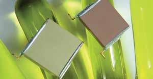
86 Trimmers Pulse Capacitors Trimmer Capacitors Half-turn Trimmers High Temperature Capacitors High Q Ultra Low ESR Capacitors Single Layer Capacitors Gain Equalizers Specialty Products Power Dividers Couplers Trimmer Ca Other products available


87 Hi-Rel and Specialty Products Thin Film Devices Hi-Rel Products Trimmer Capacitors High Capacitors Opti-Cap Capacitors Hi-Cap Capacitors Bandpass s AEC-Q2 Approved Capacitors pacitors Hi-Rel Tab Lead Capacitors StackiCap Capacitors from
New hermetically sealed panel mount filters
 New hermetically sealed panel mount filters Introduction Syfer Technology Ltd manufactures quality multilayer ceramic components supplied to a worldwide customer base. Customers utilise Syfer s components
Introduction to Syfer Technology
 Surface Mount Solder-in eramic Threaded Hermetic eramic Metallised Film Discoidal and Planar Arrays Special s and Assemblies s for Hi-Rel Applications Introduction to Technology Technology Limited is a
Surface Mount EMI Filters
 3 erminal EMI hips hese 3 terminal chips are ideally suited for EMI suppression in digital circuits and other signal lines, and are available in 0805, 1206 and 1806 size. hile the signal or dc current
Kete Microwave Electronics Co., Ltd.
 HOW TO ORDER: KTFC - X XX X - XX XX - XXX XX - XXXX - XXXX Large Dia. Body Width Rated Voltage Kete Small Dia Lead Dia. VDC/VAC Feedthru Capacitors Dielectric X=X7R, S=SL, N=NPO (-55 ~+125 ) Y=Y5U, Y5V
Kete Microwave Electronics Co., Ltd.
 HOW TO ORDER: KTFC - X XX X - XX XX - XXX XX - XXXX - XXXX Large Dia. Body Width Rated Voltage Kete Small Dia Lead Dia. VDC/VAC Feedthru Capacitors Dielectric X=X7R, S=SL, N=NPO (-55 ~+125 ) Y=Y5U, Y5V
Electromagnetic Integrated Solutions
 Complete line of coaxial EMI electromagnetic spectrum management solutions, from components to complex assemblies. Electromagnetic Integrated Solutions Capabilities & Certifications API Technologies has
The shunt capacitor is the critical element
 Accurate Feedthrough Capacitor Measurements at High Frequencies Critical for Component Evaluation and High Current Design A shielded measurement chamber allows accurate assessment and modeling of low pass
SMA - 50 Ohm Connectors
 For Flexible Cable Straight Crimp Type Plug - Captivated Contact CABLE TYPE RG-178/U, 196 1.20 +.025 f (GHz) 0-12.4 GHz 142-0402-001 142-0402-006 RG-161/U, 174,188, 316 RG-188 DS, RG-316 DS RG-58/U, 141,
HIGH TEMPERATURE 150 C 180 C 200 C 230 C 250 C 350 C
 HIGH TEMPERATURE 150 C 180 C 200 C 230 C 250 C 350 C CERAMIC CAPACITORS Catalog 3500 REV. B Presidio Components has been an industry leader in the manufacture of ceramic capacitors since 1980. We are dedicated
Systems Engineering. Passive Components. v1.2 March itic.
 Systems Engineering Passive Components Pere Palà itic http://itic.cat v1.2 March 2012 Resistors Resistor Types Resistors Ubiquitous Uncritical Surface mount chip Metal film Carbon Wirewound Precision resistors
Buried Broadband Capacitors How To Order
 Quick Select by Application and Resonant Free Bandwidth Size Resonant Free Bandwidth** Typical Insertion Loss (S21)*** 2 Cap Values in Parallel (pf) Temp. Coeff. Working VDC FIT Calc. using cont. op. temp.
11 Myths of EMI/EMC ORBEL.COM. Exploring common misconceptions and clarifying them. MYTH #1: EMI/EMC is black magic.
 11 Myths of EMI/EMC Exploring common misconceptions and clarifying them By Ed Nakauchi, Technical Consultant, Orbel Corporation What is a myth? A myth is defined as a popular belief or tradition that has
S C A 69 B 104 J W S. Capacitance Code (pf)
") SCA Series, Axial, C 3 Technology, C0G Dielectric, 50 200 VDC (Commercial Grade) Overview KEMET s SCA Series axial through-hole ceramic capacitors in C0G dielectric feature proprietary Ceramic Cased Capacitor
SCA Series, Axial, C 3 Technology, C0G Dielectric, 50 200 VDC (Commercial Grade) Overview KEMET s SCA Series axial through-hole ceramic capacitors in C0G dielectric feature proprietary Ceramic Cased Capacitor
FLTR100V10 Filter Module 75 Vdc Input Maximum, 10 A Maximum
 GE Critical Power FLTR100V10 Filter Module 75 Vdc Input Maximum, 10 A Maximum RoHS Compliant The FLTR100V10 Filter Module is designed to reduce the conducted common-mode and differential-mode noise on
Oversimplification of EMC filter selection
 Shortcomings of Simple EMC Filters Antoni Jan Nalborczyk MPE Ltd. Liverpool, United Kingdom Oversimplification of EMC filter selection to reduce size and cost can often be a false economy as anticipated
MAGNETIC PRODUCTS. SMD Beads and Chokes
 MAGNETIC PRODUCTS SMD Beads and Chokes Philips Components Magnetic Products SMD beads in tape November 1994 2 Magnetic Products Philips Components Contents page SMD Beads 8 SMD Common Mode Chokes 14 SMD
Application Note 5012
 MGA-61563 High Performance GaAs MMIC Amplifier Application Note 5012 Application Information The MGA-61563 is a high performance GaAs MMIC amplifier fabricated with Avago Technologies E-pHEMT process and
Technology in Balance
 Technology in Balance A G1 G2 B Basic Structure Comparison Regular capacitors have two plates or electrodes surrounded by a dielectric material. There is capacitance between the two conductive plates within
Application Note 5011
 MGA-62563 High Performance GaAs MMIC Amplifier Application Note 511 Application Information The MGA-62563 is a high performance GaAs MMIC amplifier fabricated with Avago Technologies E-pHEMT process and
50W TO220 High Power Resistors
 50W TO220 High Power Resistors MHP 50 Non-inductive, thin film technology. Thermally enhanced Industry standard TO220 package. RoHS compliant. Low thermal resistance, 2.3 C/W resistor hot spot to metal
C 062 C 105 K 1 R 5 T A Rated Voltage (VDC) 5 = 50 1 = = 200
 5 = 50 1 = = 200") Radial Through Hole Multilayer Ceramic Capacitors Radial, Molded, X7R Dielectric, 50 200 VDC (Commercial Grade) Overview KEMET s epoxy molded radial through-hole ceramic capacitors in X7R dielectric feature
Radial Through Hole Multilayer Ceramic Capacitors Radial, Molded, X7R Dielectric, 50 200 VDC (Commercial Grade) Overview KEMET s epoxy molded radial through-hole ceramic capacitors in X7R dielectric feature
-80 to +80V 20A 100ºC 250kHz. Input Output Current Max DC Resistance Differential Attenuation
 EMI Filter Quarter Brick MILITARY COTS EMI FILTER -80 to +80V 20A 32mΩ @ 100ºC >80dB @ 250kHz Input Output Current Max DC Resistance Differential Attenuation The Mil-COTS series of EMI filters brings SynQor
Surface Mount Multilayer Ceramic Chip Capacitors for High Frequency Applications
 Surface Mount Multilayer Ceramic Chip Capacitors for High Frequency Applications FEATURES Ultra-stable dielectric offering a Temperature Coefficient of Capacitance (TCC) of 0 ppm/ C ± 30 ppm/ C over the
MTE1 Series Isolated 1W Single Output SM DC/DC Converters
 MTE1 Series SELECTION GUIDE FEATURES Single isolated output 1kVDC Isolation Hi Pot Test Typical efficiency 86% Wide temperature performance at full 1 Watt load, 4 C to 85 C UL 69 recognised 3.3V, 5V, 12V,
B. Flip-Chip Technology
 B. Flip-Chip Technology B1. Level 1. Introduction to Flip-Chip techniques B1.1 Why flip-chip? In the development of packaging of electronics the aim is to lower cost, increase the packaging density, improve
Design for EMI & ESD compliance DESIGN FOR EMI & ESD COMPLIANCE
 DESIGN FOR EMI & ESD COMPLIANCE All of we know the causes & impacts of EMI & ESD on our boards & also on our final product. In this article, we will discuss some useful design procedures that can be followed
COPYRIGHT 2013 LED ENGIN. ALL RIGHTS RESERVED. LZ1-00R500 (1.0 08/23/13)
") 940nm Infrared LED Emitter LZ1-00R500 Key Features High Efficacy 940nm 2W Infrared LED Ultra-small foot print 4.4mm x 4.4mm Surface mount ceramic package with integrated glass lens Very low Thermal Resistance
940nm Infrared LED Emitter LZ1-00R500 Key Features High Efficacy 940nm 2W Infrared LED Ultra-small foot print 4.4mm x 4.4mm Surface mount ceramic package with integrated glass lens Very low Thermal Resistance
LGH High Voltage Connectors
 Introduction Product Facts No exposed high voltage parts Space saving maximum performance from small size and weight Fast connect and disconnect Wide temperature range -67 F to +257 F [-55 C to +5 C],
SMA 50 Ohm Connectors Alphabetical Index INCHES (MILLIMETERS) CUSTOMER DRAWINGS AVAILABLE ON REQUEST
 CUSTOMER DRAWINGS AVAILABLE ON REQUEST") SMA 50 Ohm Connectors Alphabetical Index SMA Connectors - 50 Ohm Bulkhead Mount... 20 Custom Feedthroughs... 48 Dummy Loads... 37 End Launch... 16 Field Replaceable... 28 Flexible Cable... 8 In-Series
SMA 50 Ohm Connectors Alphabetical Index SMA Connectors - 50 Ohm Bulkhead Mount... 20 Custom Feedthroughs... 48 Dummy Loads... 37 End Launch... 16 Field Replaceable... 28 Flexible Cable... 8 In-Series
NXF1 Series Isolated 1W Regulated Single Output DC-DC Converters
 www.murata-ps.com NXF1 Series SELECTION GUIDE FEATURES UL69 recognition pending Output regulation
Surface Mount Multilayer Ceramic Chip Capacitors DSCC Qualified Type 03028
 Surface Mount Multilayer Ceramic Chip Capacitors DSCC Qualified Type 03028 FEATURES US defense supply center approved Federal stock control number, Available CAGE CODE 2770A Available Small case size (0603)
EClamp2340C. EMI Filter and ESD Protection for Color LCD Interface PRELIMINARY. PROTECTION PRODUCTS - EMIClamp TM Description.
 PROTETION PRODUTS - EMIlamp TM Description The Elamp TM 0 is a low pass filter array with integrated TVS diodes. It is designed to suppress unwanted EMI/RFI signals and provide electrostatic discharge
FLTR100V20 Filter Module 75 Vdc Input Maximum, 20 A Maximum
 GE Critical Power FLTR100V20 Filter Module 75 Vdc Input Maximum, 20 A Maximum RoHS Compliant The FLTR100V20 Filter Module is designed to reduce the conducted common-mode and differential-mode noise on
CHQ SERIES. Surface Mount Chip Capacitors: Ultra High Frequency
 26 High Frequency Measurement and Performance of High Multilayer Ceramic Capacitors Introduction Capacitors used in High Frequency applications are generally used in two particular circuit applications:
Class-D Audio Power Amplifiers: PCB Layout For Audio Quality, EMC & Thermal Success (Home Entertainment Devices)
") Class-D Audio Power Amplifiers: PCB Layout For Audio Quality, EMC & Thermal Success (Home Entertainment Devices) Stephen Crump http://e2e.ti.com Audio Power Amplifier Applications Audio and Imaging Products
Class-D Audio Power Amplifiers: PCB Layout For Audio Quality, EMC & Thermal Success (Home Entertainment Devices) Stephen Crump http://e2e.ti.com Audio Power Amplifier Applications Audio and Imaging Products
Understanding and Optimizing Electromagnetic Compatibility in Switchmode Power Supplies
 Understanding and Optimizing Electromagnetic Compatibility in Switchmode Power Supplies 1 Definitions EMI = Electro Magnetic Interference EMC = Electro Magnetic Compatibility (No EMI) Three Components
Common myths, fallacies and misconceptions in Electromagnetic Compatibility and their correction.
 Common myths, fallacies and misconceptions in Electromagnetic Compatibility and their correction. D. A. Weston EMC Consulting Inc 22-3-2010 These are some of the commonly held beliefs about EMC which are
CRL2 Series. Isolated 2W Single Output DC/DC Converters FEATURES PRODUCT OVERVIEW
 www.murata-ps.com CRL2 Series SELECTION GUIDE Order Code Nominal Input Voltage Output Voltage Output Current Input Current at Rated Load Load Regulation (Typ) Load Regulation (Max) Ripple & Noise (Typ)
Advanced Topics in EMC Design. Issue 1: The ground plane to split or not to split?
 NEEDS 2006 workshop Advanced Topics in EMC Design Tim Williams Elmac Services C o n s u l t a n c y a n d t r a i n i n g i n e l e c t r o m a g n e t i c c o m p a t i b i l i t y e-mail timw@elmac.co.uk
MTE1 Series Isolated 1W Single Output SM DC/DC Converters
 MTE1 Series SELECTION GUIDE FEATURES Single isolated output 1kVDC Isolation Typical efficiency 86% Wide temperature performance at full 1 Watt load, 4 C to 85 C UL 94V- Package material 3.3V, 5V, 12V,
CR0603/CR0805/CR Chip Resistors
 *RoHS COMPLIANT Features RoHS compliant* Power rating at 7 C: CR63 -.1 W, CR85 -.125 W, CR126 -.25 W Tight tolerances of bottom electrode width Suitable for all types of soldering processes Three layer
MER1 Series 1kVDC Isolated 1W Single Output DC/DC Converters
 www.murata-ps.com MER1 Series SELECTION GUIDE Order Code Nominal Input Voltage Output Voltage Output Current Input Current at Rated Load Load Regulation (Typ) Load Regulation (Max) Ripple & Noise (Typ)
Features. Circuit Schematic. Typical Electrical Characteristics. Applications. Surface Mount EMI Filters Three Terminal Chips. Three Terminal Chips
 Features Excellent performance in high current applications Non-polar, surface mountable Superior filtering characteristics Superb ability to withstand transient voltages and surge Offers exceptional solderability
EMI Filter Connectors
 EMI Filter Connectors Then and Now Leonard Krantz Engineering Manager Amphenol Aerospace 1 Environment Current requirements dictate EMI protection for commercial and military systems. EMI requirements
EMC Design Guidelines C4ISR EQUIPMENT & SYSTEMS
 EMC Design Guidelines C4ISR EQUIPMENT & SYSTEMS 1.1. SHIELDING Enclosed structure (equipment box or chassis in outside RF environment) should provide at least 100 db of RF shielding at 1 MHz, 40 db at
SELECTION GUIDE. Nominal Input Voltage Output Voltage. Output Current
 www.murata-ps.com SELECTION GUIDE Order Code Nominal Input Voltage Output Current Input Current at Rated Load Load Regulation (Typ) Load Regulation (Max) Ripple & Noise (Typ) 1 Ripple & Noise (Max) 1 Efficiency
American Power Design, Inc.
 FEATURES 4 Customer Selects Output Voltage 4 Outputs to 28 Vdc 4 Wide Input Ranges (10-20Vdc, 18-36Vdc, 20-60Vdc, 36-72Vdc) 4 Excellent Line & Load Regulation 4 Low Output Ripple 4 500 Vdc Output Isolation
Types MCH and MCHN Multilayer High RF Power Capacitors
 2500 & 4000 Volt RF Capacitors for Medical Imaging Coils, Plasma Generators, VHF/UHF Power Amplifiers and Antenna Tuning with Nonmagnetic Option The flexible aluminum silicate dielectric eliminates cracking
BNX. Block Type EMIFILr. Series Line Up Function Example Product Detail!Caution/Notice Soldering and Mounting Packaging Design Kits. C31E.
 CE.pdf Mar.28,2 NX Series Line Up Function Example Product Detail!Caution/Notice Soldering and Mounting Packaging Design Kits 88 88 9 95 97 2 22 CE.pdf Mar.28,2 NX Series Line Up / Function Example Type
SELECTION GUIDE. Nominal Input Voltage Output Voltage. Output Current
 www.murata-ps.com CRV2 Series SELECTION GUIDE Order Code Nominal Input Voltage Output Voltage Output Current Input Current at Rated Load Load Regulation (Typ) Load Regulation (Max) Ripple & Noise (Typ)
Suppression Techniques using X2Y as a Broadband EMI Filter IEEE International Symposium on EMC, Boston, MA
 Suppression Techniques using X2Y as a Broadband EMI Filter Jim Muccioli Tony Anthony Dave Anthony Dale Sanders X2Y Attenuators, LLC Erie, PA 16506-2972 www.x2y.com Email: x2y@x2y.com Bart Bouma Yageo/Phycomp
LM M-A-300 Surface Mount Pin Diode Limiter, 20 MHz 8 GHz Datasheet
 LM200802-M-A-300 Surface Mount Pin Diode Limiter, 20 MHz 8 GHz Datasheet Features Broadband Performance: 20 MHz 8 GHz Surface Mount Limiter in Compact Outline: 8 mm L x 5 mm W x 2.5 mm H Incorporates NIP
The packaging of EMI and TVS elements
 Introduction to Filter Connectors Introduction EMI Filter and Transient Voltage Suppression Packaging The packaging of EMI and TVS elements in standard connectors is an important element in effective EMC
Plane Crazy, Part 2 BEYOND DESIGN. by Barry Olney
 by Barry Olney column BEYOND DESIGN Plane Crazy, Part 2 In my recent four-part series on stackup planning, I described the best configurations for various stackup requirements. But I did not have the opportunity
RFI & EMI Components and Subsystems
 RFI & EMI Components and Subsystems In 1979 Filter Networks began manufacturing RFI and EMI components. Filter Networks was acquired in 1997 by EMI Technologies. Our mission then, as now, was simple: to
Passive Components around ADAS Applications By Ron Demcko, AVX Fellow, AVX Corporation
 Passive Components around ADAS Applications By Ron Demcko, AVX Fellow, AVX Corporation The importance of high reliability - high performance electronics is accelerating as Advanced Driver Assistance Systems
QPI-5L. 14 Amp Active EMI Filter for 24 V DC Bus. Features. Description. Applications 查询 QPI-5L 供应商. QuietPower
 查询 5L 供应商 5L QuietPower 14 Amp Active EMI Filter for 24 V DC Bus Description The 5 active EMI filter attenuates conducted common-mode (CM) and differential-mode (DM) noise over the CISPR22 frequency range
Capacitor Terminations. and Soldering Recommendations
 I. TERMINATION TYPES Our capacitors are delivered with one of the following terminations (for technical reasons, only a limited number of termination types are available in certain cases). All our terminations
Transistor Installation Instructions
 INTRODUCTION When inserting high power RF transistor packages into amplifier circuits there are two important objectives. Firstly, removing heat and, secondly, providing a longterm reliable solder joint
MAAM Wideband Amplifier 10 MHz - 40 GHz Rev. V2. Features. Functional Schematic. Description. Pin Configuration. Ordering Information 1,2
 MAAM-1119 1 MHz - 4 GHz Rev. V2 Features 13 db Gain Ω Input / Output Match +18 dbm Output Power + V DC, 19 ma Lead-Free mm 9-lead LGA Package RoHS* Compliant and 26 C Reflow Compatible Description The
Frequency Range: MHz. Efficiency: 80% Temperature Range: -20 to 65 C Max VSWR: 3:1. Class: Supply Voltage: 32.0V
 Part Number Revision 0.B Release Date October 19, 2007 Revision Notes Final production release Amplifier Name Technical Specifications Summary Frequency Range: 86-108 MHz P1dB: 500 Watts CW Class: C Supply
Choosing and using filters
 Page 1 of 8 Choosing and using filters By Eur Ing Keith Armstrong CEng MIEE MIEEE How does a designer select which filter to use for which application? This article aims to help him or her make these decisions.
High Precision Wraparound - Wide Ohmic Value Range Thin Film Chip Resistors
 P Vishay Sfernice High Precision Wraparound - Wide Ohmic Value Range For low noise and precision applications, superior stability, low temperature coefficient of resistance, and low voltage coefficient,
NCM6 Series. Isolated 6W Wide Input Single & Dual Output DC/DC Converters FEATURES PRODUCT OVERVIEW
 NCM Series FEATURES UL9 Reinforced Insulation ANSI/AAMI ES-, MOPP/ MOOP s recognised : Wide range voltage input Operating temperature range C to 8 C.kVDC isolation Hi Pot Test Typical efficiency to 88%
CGJ series l High Reliability Series
 CGJ series l High Reliability Series Contents Purpose / Objectives TDK MLCC Lineup Series Concept Cap Range Features Ap p lic a tions Design Tools/Resources Part Number De s c rip tion Summary Capacitors
RF OUT / N/C RF IN / V G
 MAAM-111 MHz - 2 GHz Rev. V2 Features Functional Schematic 12 db Gain Ω Input / Output Match over Gain Range 3 db Gain Control with to -2 V Control +18 dbm Output Power + V, -. V DC, 7 ma Lead-Free 1.
RFSWLM S-Band Switch Limiter Module
 PRELIMINARY RFSWLM-2420-131 S-Band Switch Limiter Module Features: Surface Mount S- Band Switch Limiter Module 5mm x 8mm x 2.5mm Frequency Range: 2 to 4 GHz Higher Average Power Handling than Plastic Packages
American Power Design, Inc.
 FEATURES 4 Customer Selects Output Voltage 4 Outputs to 28 Vdc 4 Wide Input Ranges (10-20Vdc, 18-36Vdc, 20-60Vdc, 36-72Vdc) 4 Excellent Line & Load Regulation 4 500 Vdc Output Isolation 4 Continuous Short
NCS3 Series Isolated 3W 4:1 Input Single Output DC-DC Converters
 FEATURES UL 9 recognised 4:1 Wide range voltage input Operating temperature range - C to 85 C with derating 1.5 kvdc Isolation Hi Pot Test 3.3V, 5V, & 15V outputs No electrolytic capacitors Continuous
Anaren 0805 (B0809J50ATI) balun optimized for Texas Instruments CC1100/CC1101 Transceiver
 balun optimized for Texas Instruments CC1100/CC1101 Transceiver") (ANN-2005) Rev B Page 1 of 13 Anaren 0805 (B0809J50ATI) balun optimized for Texas Instruments CC1100/CC1101 Transceiver Trong N Duong RF Co-Op Nithya R Subramanian RF Engineer Introduction The tradeoff
(ANN-2005) Rev B Page 1 of 13 Anaren 0805 (B0809J50ATI) balun optimized for Texas Instruments CC1100/CC1101 Transceiver Trong N Duong RF Co-Op Nithya R Subramanian RF Engineer Introduction The tradeoff
Application Bulletin 240
 Application Bulletin 240 Design Consideration CUSTOM CAPABILITIES Standard PC board fabrication flexibility allows for various component orientations, mounting features, and interconnect schemes. The starting
Types MCM and MIN SMT Clad RF Capacitors
 Multilayer High Power, High Temperature Mica and PTFE Capacitors Specifications Complies with the EU Directive 2002/95/EC requirement restricting the use of Lead (Pb), Mercury (Hg), Cadmium (Cd), Hexavalent
COPYRIGHT 2013 LED ENGIN. ALL RIGHTS RESERVED. LZ4-00R300 (6.0-09/19/13)
") High Luminous Efficacy Far Red LED Emitter LZ4-00R300 Key Features High Efficacy 6.3W Far Red LED Ultra-small foot print 7.0mm x 7.0mm Surface mount ceramic package with integrated glass lens Very low
High Luminous Efficacy Far Red LED Emitter LZ4-00R300 Key Features High Efficacy 6.3W Far Red LED Ultra-small foot print 7.0mm x 7.0mm Surface mount ceramic package with integrated glass lens Very low
Types MC and MCN Multilayer RF Capacitors
 High-Frequency, High-Power, High-Voltage Chips with Nonmagnetic Option Rugged fexibility and compatibility with FR4 boards make Type MC and MCN capacitors ideal for use where other multilayer caps aren
APPLICATION NOTE FOR PA.710A ANTENNA INTEGRATION
 APPLICATION NOTE FOR PA.710A ANTENNA INTEGRATION APN-11-8-001/B Page 1 of 22 1. TABLE OF CONTENTS 1. TABLE OF CONTENTS... 2 2. BASICS... 4 3. APPLICATIONS... 5 4. IMPEDANCE... 5 5. BANDWIDTH... 5 6. GAIN...
High Voltage Charge Pumps Deliver Low EMI
 High Voltage Charge Pumps Deliver Low EMI By Tony Armstrong Director of Product Marketing Power Products Linear Technology Corporation (tarmstrong@linear.com) Background Switching regulators are a popular
X2Y versus CM Chokes and PI Filters. Content X2Y Attenuators, LLC
 X2Y versus CM Chokes and PI Filters 1 Common Mode and EMI Most EMI compliance problems are common mode emissions. Only 10 s of uas in external cables are enough to violate EMC standards. 2 Common Mode
Reducing Motor Drive Radiated Emissions
 Volume 2, Number 2, April, 1996 Application Note 107 Donald E. Fulton Reducing Motor Drive Radiated Emissions Introduction This application note discusses radiated emissions (30 Mhz+) of motor drives and
Internal Model of X2Y Chip Technology
 Internal Model of X2Y Chip Technology Summary At high frequencies, traditional discrete components are significantly limited in performance by their parasitics, which are inherent in the design. For example,
COTS EMI FILTER -500V
 Passive Filter Half-Brick MILITARY COTS EMI FILTER -500V to +500V 9A 80mΩ @ 100 C >80dB @ 250kHz Continuous Input Output Current Max. DC Resistance Differential Attenuation FULL POWER OPERATION: -55ºC
AS9100 and ISO 9001 certified ISO certified
 front cover Company Overview Dielectric Laboratories, Inc. (DLI) is your global partner for application specific microwave and millimeter wave components serving customers in fiber optic, wireless, medical,
DATA SHEET SURFACE-MOUNT CERAMIC MULTILAYER CAPACITORS High-voltage SC type: NP0/X7R (Pb Free & RoHS compliant)
") DATA SHEET SURFACE-MOUNT CERAMIC MULTILAYER CAPACITORS High-voltage SC type: (Pb Free & RoHS compliant) 2.2 pf to 4.7 nf Product specification Mar 1, 2007 V. 0 Product specification 2 SCOPE This specification
DATA SHEET SURFACE-MOUNT CERAMIC MULTILAYER CAPACITORS High-voltage SC type: (Pb Free & RoHS compliant) 2.2 pf to 4.7 nf Product specification Mar 1, 2007 V. 0 Product specification 2 SCOPE This specification
MTC1 Series Isolated 1W SM 2:1 Input Single Output DC-DC Converters
 MTC1 Series SELECTION GUIDE FEATURES UL 95 recognised for reinforced insulation ANSI/AAMI ES1-1, 1 MOPP/ 2 MOOPs recognised 3kVAC isolation test voltage Hi Pot Test Continuous short circuit protection
Surface Mount EMI Filters
 Surface Mount EMI Filters our family of surface mount filters is designed to provide a range of high performance EMI filtering options with a minimal PCB footprint Three Terminal Chips offer superior ability
ponents Com ped Lum Lumped Components
 Lumped Components Lumped Components K&L Microwave offers Lumped Component filters with a broad selection of frequencies, topologies, and mechanical configurations. Use of standard packages has enabled
FLTR75V05 Filter Module 75 Vdc Input Maximum, 5 A Maximum
 GE Critical Power FLTR75V05 Filter Module 75 Vdc Input Maximum, 5 A Maximum RoHS Compliant The FLTR75V05 Filter Module is designed to reduce the conducted common-mode and differentialmode noise on input
SELECTION GUIDE. Nominal Input Voltage. Output Voltage
 MTE1 Series SELECTION GUIDE FEATURES Single isolated output 1kVDC Isolation Efficiency up to 88% Power density 1.8W/cm 3 Wide temperature performance at full 1 Watt load, 4 C to 85 C UL 94V- Package material
MER1 Series 1kVDC Isolated 1W Single Output DC-DC Converters
 www.murata-ps.com MER1 Series SELECTION GUIDE Order Code Nominal Input Voltage Output Voltage Output Current Input Current at Rated Load Load Regulation (Typ) Load Regulation (Max) Ripple & Noise (Typ)
APPLICATION NOTE FOR PA.710.A ANTENNA INTEGRATION
 APPLICATION NOTE FOR PA.710.A ANTENNA INTEGRATION APN-13-8-005/B/NB Page 1 of 17 1. TABLE OF CONTENTS 1. TABLE OF CONTENTS... 2 2. BASICS... 3 3. APPLICATIONS... 4 4. IMPEDANCE... 4 5. BANDWIDTH... 4 6.
Chapter 12: Transmission Lines. EET-223: RF Communication Circuits Walter Lara
 Chapter 12: Transmission Lines EET-223: RF Communication Circuits Walter Lara Introduction A transmission line can be defined as the conductive connections between system elements that carry signal power.
HigH Reliability emi FilteR
 Passive Filter HigH Reliability emi FilteR -400V to +400V 1A 450mΩ @ 125 C >50dB @ 500kHz Continuous Input Output Current Max. DC Resistance Differential Attenuation Full PoweR operation: -55ºC to +125ºC
PAGE 1/6 ISSUE Jul SERIES Micro-SPDT PART NUMBER R516 XXX 10X R 516 _ 1 0 _
 PAGE 1/6 ISSUE Jul-24-2017 SERIES Micro-SPDT PART NUMBER R516 XXX 10X R516 series: the RAMSES concept merges with the SLIM LINE technology, breaking up the frequency limits of SMT switches : - FULL SMT
Corcom Product Guide. Introduction
 Introduction Corcom brand SignalSentry filtered modular jack series product combines different levels of filtering with and modular jacks to solve signal line noise problems and crosstalk. Corcom brand
Surface Mount Limiter, GHz
 Surface Mount Limiter, 2.9 3.3 GHz LM2933-Q-B-301 Datasheet Features Surface Mount Limiter in Compact Package: 8 mm L x 5 mm W x 2.5 mm H Incorporates PIN Limiter Diodes, DC Blocks, Schottky Diode & DC
Application Note 5026
 Surface Laminar Circuit (SLC) Ball Grid Array (BGA) Eutectic Surface Mount Assembly Application Note 5026 Introduction This document outlines the design and assembly guidelines for surface laminar circuitry
Categorized by the type of core on which inductors are wound:
 Inductors Categorized by the type of core on which inductors are wound: air core and magnetic core. The magnetic core inductors can be subdivided depending on whether the core is open or closed. Equivalent
Mini Evaluation Board for Filterless Class-D Audio Amplifier EVAL-SSM2301-MINI
 Mini Evaluation Board for Filterless Class-D Audio Amplifier EVAL-SSM30-MINI FEATURES DC power supply accepts.5 V to 5.5 V Single-ended and differential input capability Extremely small board size allows
by Shoichiro Hirai *, Naoya Arakawa *, Takahiro Ueno *2, Hiroki Hamada *2, Isao Tomomatsu *3 and Yoichi Iso *4 1. INTRODUCTION
 by Shoichiro Hirai *, Naoya Arakawa *, Takahiro Ueno *2, Hiroki Hamada *2, Isao Tomomatsu *3 and Yoichi Iso *4 Recently the development of information-intensive society around us is quite ABSTRACT remarkable,
COPYRIGHT 2015 LED ENGIN. ALL RIGHTS RESERVED. LZ1-00R102 (1.0 03/27/15)
") High Luminous Efficacy Red 623nm LED Emitter LZ1-00R102 Key Features High Luminous Efficacy Red 623nm LED emitter Ultra-small foot print 4.4mm x 4.4mm Up to 1.5A drive current Surface mount ceramic package
High Luminous Efficacy Red 623nm LED Emitter LZ1-00R102 Key Features High Luminous Efficacy Red 623nm LED emitter Ultra-small foot print 4.4mm x 4.4mm Up to 1.5A drive current Surface mount ceramic package
Power Transmitter Capacitors UHF/RF High Q Ceramic Capacitors (NP0 TC) 6040C (.600 x.400 ) 6040C (.600 x.400 )
 6040C (.600 x.400 ) 6040C (.600 x.400 )") Power Transmitter Capacirs UHF/RF High Q Ceramic Capacirs (NP0 TC) (.600 x.400 ) (.600 x.400 ) Product Features High Q, High RF Current/, High RF Power, Low ESR/ESL, Low Noise, Ultra-Stable Performance.
Power Transmitter Capacirs UHF/RF High Q Ceramic Capacirs (NP0 TC) (.600 x.400 ) (.600 x.400 ) Product Features High Q, High RF Current/, High RF Power, Low ESR/ESL, Low Noise, Ultra-Stable Performance.