BIG PIXELS VS. SMALL PIXELS THE OPTICAL BOTTLENECK. Gregory Hollows Edmund Optics
|
|
|
- Alexandrina Gilmore
- 6 years ago
- Views:
Transcription

1 BIG PIXELS VS. SMALL PIXELS THE OPTICAL BOTTLENECK Gregory Hollows Edmund Optics 1
2 IT ALL STARTS WITH THE SENSOR We have to begin with sensor technology to understand the road map Resolution will continue to increase Sensor speeds will continue to increase Applications split in to two areas Microns Change in Resolution and Pixel Size Resolution in Mega Pixels Pixel Size in Microns Total Sensor Resolution in MegaPixel Expon. (Pixel Size in Microns) Expon. (Total Sensor Resolution in MegaPixel)
3 SENSOR TECHNOLOGY DEVELOPMENT 29.0mp 25.0mp Increasing Resolution 14.0mp 10.0mp 5.0mp 5.0mp 0.3mp 0.3mp 2.0mp 0.3mp 1.3mp 1.3mp 1.3mp 12.0mp 9.0mp 8.0mp 6.0mp 8.0mp 4.0mp 4.0k 16.0mp 11.0mp 1.0mp 1/3 1/2 2/3 1 4/3 28mm dia. 43mm dia.
 and resolved (b). In figure (a) the two squares are imaged onto neighboring pixels and are indistinguishable from one another.")
4 HOW DO WE DEFINE RESOLUTION? Resolution is a measurement of the imaging system's ability to reproduce object detail. Exaggerated example in which a pair of squares are not resolved(a) and resolved (b). In figure (a) the two squares are imaged onto neighboring pixels and are indistinguishable from one another. Without any space between, they appear as one large rectangle in the image. In order to distinguish them a certain amount of white space is needed, as in figure (b). This can be represented by a line pair.
5 HOW DO WE MEASURE RESOLUTION IN OPTICS? Frequency of lines is represented in line pairs over a linear spacing. Frequency or Line-pair(lp/mm) = Line-pair(lp) = 2 x Pixel
6 EXAMPLE: FIELD OF VIEW AND RESOLUTION 640 x 480 pixel (0.3 megapixels) 1600 x 1200 pixel (2 megapixels)
7 C-MOUNT SENSOR FORMATS 1 inch 9.6mm 1/3 inch 4.8mm 3.6mm 12.8mm 1/4 inch 2.4mm 3.2mm 2/3 inch 6.6mm 8.8mm Mega Pixel 15.15mm 1/2 inch 4.8mm 1.3 inch 6.4mm 15.15mm Common Area Sensor (4:3 Aspect Ratio) Common Name = Old Videcon Tube Diameter
8 IMAGE QUALITY Resolution Contrast
9 WHAT IS MEANT BY CONTRAST? Contrast describes the separation in intensity between blacks and whites. % Contrast = I max - I min I max + I min Reproducing object contrast is as important as reproducing object resolution. For an image to appear well defined black details need to appear black and the white details appear white. The greater the difference in intensity between a black and white line, the better the contrast.
10 HOW ARE CONTRAST AND RESOLUTION LINKED? Resolution and contrast are closely linked. Resolution is defined at a specific contrast. The typical limiting contrast of 10% is often used to define the limiting resolution level. For the human eye a contrast of 1-2% is often used to define resolution.
11 HOW DOES CONTRAST DEPEND ON FREQUENCY? Suppose two dots are placed close to each other and imaged through a lens. The two spots will blur slightly. Moving the spots closer causes the blur to overlap and contrast is decreased. When the spots are close enough that the contrast becomes limiting, the spacing is our resolution. At each spacing of the spots we obtain a specific contrast. We can plot this information in the form of a Modulation Transfer Function (MTF).

12 FREQUENCY AND MODULATION TRANSFER FUNCTION (MTF)
13 HOW DOES DIFFRACTION AND F/# AFFECT PERFORMANCE? Not even a perfectly designed and manufactured lens can accurately reproduce an object s detail and contrast. Diffraction will limit the performance of an ideal lens. The size of the aperture will affect the diffraction limit of a lens. The smallest achievable spot of a lens = 2.44 x wavelength of light x (F/#) F/# describes the light gathering ability of an imaging lens (lower F/# lenses collect more light). As lens aperture decreases, F/# increases.

14 HOW DOES DIFFRACTION AND F/# AFFECT PERFORMANCE? Not even a perfectly designed and manufactured lens can accurately reproduce an object s detail and contrast. Diffraction will limit the performance of an ideal lens. The size of the aperture will affect the diffraction limit of a lens. The smallest achievable spot of a lens = 2.44 x wavelength of light x (F/#) F/# describes the light gathering ability of an imaging lens (lower F/# lenses collect more light). As lens aperture decreases, F/# increases.
15 HOW DOES DIFFRACTION AND F/# AFFECT PERFORMANCE? The smallest achievable spot of a lens = 2.44 x wavelength of light x (F/#) 9 micron pixels 4.5 micron pixels ~f/8 ~f/4 ~f/2 2.2 micron pixels
16 WHAT IS A BETTER MTF? Depends on the application. Depends on the detector. Is limiting resolution important? Is high contrast at low frequencies important?
17 MODULATION TRANSFER FUNCTION (MTF) CURVE

18 ARE LENSES THE ONLY THINGS WITH MTF S? Each component of an imaging system has an MTF associated with it. Cameras, cables, monitor, capture boards, and eyes all have MTFs. Below is an example of the MTF of a typical CCD camera.

19 HOW DO INDIVIDUAL MTFS FORM A SYSTEM MTF? A rough estimate of system resolution can be found using the weakest link. This assumes that the system resolution will be determined by the lowest resolution of its components. A more accurate system resolution is one where the MTFs of each component are looked at and combined as a whole. Each component has its own MTF (Lens, camera, cables, capture board, and monitor). By multiplying each MTF we get a System MTF.
20 WHAT IS MEANT BY CONTRAST? Contrast describes the separation in intensity between blacks and whites. % Contrast = I max - I min I max + I min Reproducing object contrast is as important as reproducing object resolution. For an image to appear well defined black details need to appear black and the white details appear white. The greater the difference in intensity between a black and white line, the better the contrast.
21 HOW DOES DIFFRACTION AND F/# AFFECT PERFORMANCE? The smallest achievable spot of a lens = 2.44 x wavelength of light x (F/#) 9 micron pixels 4.5 micron pixels ~f/8 ~f/4 ~f/2 2.2 micron pixels

22 REAL WORLD LENS PERFORMANCE 5 MP 1/2.5 Inch 2.2 micron pixel 227lp/mm 113lp/mm 5 MP 2/3 Inch 3.45 micron pixel 145 lp/mm 72 lp/mm 4 MP 1.2 Inch 7.4 micron pixel 67 lp/mm 33 lp/mm Analysis on 50mm fl. at f/4, 300mm working distance Waveband is white light created by RGB LED s Assuming a 10% contrast noise floor for the sensors LP for each sensor are for 2 pixels per line pair and 4 pixels per line pair

23 HOW IS RESOLUTION TESTED? By imaging a test target, a limiting resolution can be found. Targets consist of varying frequencies. A common test target is the bar target. Bar targets have sets of line pairs. Orthogonal bars allow tests of astigmatic errors. Bar targets are limited by a finite number of steps in frequency.
24 REAL WORLD LENS PERFORMANCE 5 MP 1/2.5 Inch 2.2 micron pixel 113lp/mm Contrast: 30.3% 227lp/mm Contrast: 8.8%
25 REAL WORLD LENS PERFORMANCE 5 MP 2/3 Inch 3.45 micron pixel 72 lp/mm Contrast: 48% 145 lp/mm Contrast: 24.6%
26 REAL WORLD LENS PERFORMANCE 4 MP 1.2 Inch 7.4 micron pixel 33 lp/mm Contrast: 55.3% 67 lp/mm Contrast: 33.6%


27 REAL WORLD LENS PERFORMANCE 5 MP 1/2.5 Inch 5MP 2/3 Inch 4MP 1.2 Inch 2.2 micron pixel 3.45 micron pixel 7.4 micron pixel 30.3% Contrast 48.0% Contrast 55.3% Contrast 8.8% Contrast 24.6% Contrast 33.6% Contrast


28 HOW DOES DIFFRACTION AND F/# AFFECT PERFORMANCE? The smallest achievable spot of a lens = 2.44 x wavelength of light x (F/#)
")

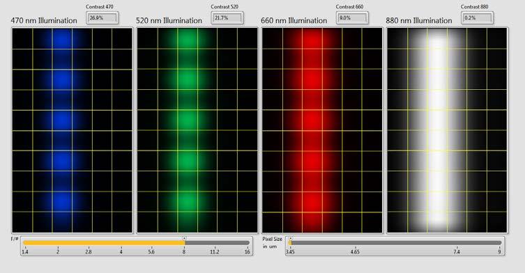
29 COLOR (WAVELENGTH) MATTERS 3b 660nm Light 470nm Light
")
30 COLOR (WAVELENGTH) MATTERS
31 COLOR (WAVELENGTH) MATTERS
32 F2.8
33 F5.6
34 F8
35 YOU HAVE TO COMPROMISE BETWEEN RESOLUTION AND DOF


36 RESOLUTION AND DOF TRADEOFF
37 IT ALL STARTS WITH THE SENSOR We have to begin with sensor technology to understand the road map Resolution will continue to increase Sensor speeds will continue to increase Applications split in to two areas Microns Change in Resolution and Pixel Size Resolution in Mega Pixels Pixel Size in Microns Total Sensor Resolution in MegaPixel Expon. (Pixel Size in Microns) Expon. (Total Sensor Resolution in MegaPixel) Year 37
38 FINALLY, DO YOUR HOMEWORK! Optics can process images at the speed of light. Give it the time it deserves! Specify what you need as a system not just components. Expect a lot from optical suppliers. They should know much more then just lens design.
39 Gregory Hollows Director, Imaging Business Unit Edmund Optics Barrington, New Jersey USA Phone: (856)
Imaging Optics Fundamentals
 Imaging Optics Fundamentals Gregory Hollows Director, Machine Vision Solutions Edmund Optics Why Are We Here? Topics for Discussion Fundamental Parameters of your system Field of View Working Distance
Using Optics to Optimize Your Machine Vision Application
 Expert Guide Using Optics to Optimize Your Machine Vision Application Introduction The lens is responsible for creating sufficient image quality to enable the vision system to extract the desired information
Optical basics for machine vision systems. Lars Fermum Chief instructor STEMMER IMAGING GmbH
 Optical basics for machine vision systems Lars Fermum Chief instructor STEMMER IMAGING GmbH www.stemmer-imaging.de AN INTERNATIONAL CONCEPT STEMMER IMAGING customers in UK Germany France Switzerland Sweden
IMAGE SENSOR SOLUTIONS. KAC-96-1/5" Lens Kit. KODAK KAC-96-1/5" Lens Kit. for use with the KODAK CMOS Image Sensors. November 2004 Revision 2
 KODAK for use with the KODAK CMOS Image Sensors November 2004 Revision 2 1.1 Introduction Choosing the right lens is a critical aspect of designing an imaging system. Typically the trade off between image
On spatial resolution
 On spatial resolution Introduction How is spatial resolution defined? There are two main approaches in defining local spatial resolution. One method follows distinction criteria of pointlike objects (i.e.
ECEN 4606, UNDERGRADUATE OPTICS LAB
 ECEN 4606, UNDERGRADUATE OPTICS LAB Lab 2: Imaging 1 the Telescope Original Version: Prof. McLeod SUMMARY: In this lab you will become familiar with the use of one or more lenses to create images of distant
TECHSPEC COMPACT FIXED FOCAL LENGTH LENS
 Designed for use in machine vision applications, our TECHSPEC Compact Fixed Focal Length Lenses are ideal for use in factory automation, inspection or qualification. These machine vision lenses have been
Criteria for Optical Systems: Optical Path Difference How do we determine the quality of a lens system? Several criteria used in optical design
 Criteria for Optical Systems: Optical Path Difference How do we determine the quality of a lens system? Several criteria used in optical design Computer Aided Design Several CAD tools use Ray Tracing (see
Variable microinspection system. system125
 Variable microinspection system system125 Variable micro-inspection system Characteristics Large fields, high NA The variable microinspection system mag.x system125 stands out from conventional LD inspection
Optical design of a high resolution vision lens
 Optical design of a high resolution vision lens Paul Claassen, optical designer, paul.claassen@sioux.eu Marnix Tas, optical specialist, marnix.tas@sioux.eu Prof L.Beckmann, l.beckmann@hccnet.nl Summary:
Topic 6 - Optics Depth of Field and Circle Of Confusion
 Topic 6 - Optics Depth of Field and Circle Of Confusion Learning Outcomes In this lesson, we will learn all about depth of field and a concept known as the Circle of Confusion. By the end of this lesson,
ABOUT RESOLUTION. pco.knowledge base
 The resolution of an image sensor describes the total number of pixel which can be used to detect an image. From the standpoint of the image sensor it is sufficient to count the number and describe it
There is a range of distances over which objects will be in focus; this is called the depth of field of the lens. Objects closer or farther are
 Chapter 25 Optical Instruments Some Topics in Chapter 25 Cameras The Human Eye; Corrective Lenses Magnifying Glass Telescopes Compound Microscope Aberrations of Lenses and Mirrors Limits of Resolution
Optics: An Introduction
 It is easy to overlook the contribution that optics make to a system; beyond basic lens parameters such as focal distance, the details can seem confusing. This Tech Tip presents a basic guide to optics
MML-High Resolution 5M Series
 Fixed Magnification Series -High Resolution 5M Series High-resolution models that possess the best contrast and NA of all Series. Image acquisition with even higher image quality is realized by combining
Laser Diode Mounting Kits
 Laser Diode Mounting Kits For Ø5.6mm and Ø9mm Laser Diodes Complete Mounting System with Collimating Lens If your work involves laser diodes, you ll appreciate the benefits of Optima s laser diode mounting
A Pin-Hole Projection System: Status
 Spot-o-Matic A Pin-Hole Projection System: Status Wolfgang Lorenzon Work performed by: Michael Borysow Nate Barron SNAP Detector Design We need to test: Intra-pixel response Lateral Charge Diffusion Must
Evaluating Commercial Scanners for Astronomical Images. The underlying technology of the scanners: Pixel sizes:
 Evaluating Commercial Scanners for Astronomical Images Robert J. Simcoe Associate Harvard College Observatory rjsimcoe@cfa.harvard.edu Introduction: Many organizations have expressed interest in using
Advanced Camera and Image Sensor Technology. Steve Kinney Imaging Professional Camera Link Chairman
 Advanced Camera and Image Sensor Technology Steve Kinney Imaging Professional Camera Link Chairman Content Physical model of a camera Definition of various parameters for EMVA1288 EMVA1288 and image quality
Reikan FoCal Aperture Sharpness Test Report
 Focus Calibration and Analysis Software Test run on: 26/01/2016 17:02:00 with FoCal 2.0.6.2416W Report created on: 26/01/2016 17:03:39 with FoCal 2.0.6W Overview Test Information Property Description Data
ECEN 4606, UNDERGRADUATE OPTICS LAB
 ECEN 4606, UNDERGRADUATE OPTICS LAB Lab 3: Imaging 2 the Microscope Original Version: Professor McLeod SUMMARY: In this lab you will become familiar with the use of one or more lenses to create highly
Reikan FoCal Aperture Sharpness Test Report
 Focus Calibration and Analysis Software Reikan FoCal Sharpness Test Report Test run on: 26/01/2016 17:14:35 with FoCal 2.0.6.2416W Report created on: 26/01/2016 17:16:16 with FoCal 2.0.6W Overview Test
CODE V Introductory Tutorial
 CODE V Introductory Tutorial Cheng-Fang Ho Lab.of RF-MW Photonics, Department of Physics, National Cheng-Kung University, Tainan, Taiwan 1-1 Tutorial Outline Introduction to CODE V Optical Design Process
Chapters 1-3. Chapter 1: Introduction and applications of photogrammetry Chapter 2: Electro-magnetic radiation. Chapter 3: Basic optics
 Chapters 1-3 Chapter 1: Introduction and applications of photogrammetry Chapter 2: Electro-magnetic radiation Radiation sources Classification of remote sensing systems (passive & active) Electromagnetic
Chapter 25. Optical Instruments
 Chapter 25 Optical Instruments Optical Instruments Analysis generally involves the laws of reflection and refraction Analysis uses the procedures of geometric optics To explain certain phenomena, the wave
Reikan FoCal Aperture Sharpness Test Report
 Focus Calibration and Analysis Software Reikan FoCal Sharpness Test Report Test run on: 10/02/2016 19:57:05 with FoCal 2.0.6.2416W Report created on: 10/02/2016 19:59:09 with FoCal 2.0.6W Overview Test
Better Imaging with a Schmidt-Czerny-Turner Spectrograph
 Better Imaging with a Schmidt-Czerny-Turner Spectrograph Abstract For years, images have been measured using Czerny-Turner (CT) design dispersive spectrographs. Optical aberrations inherent in the CT design
Reikan FoCal Aperture Sharpness Test Report
 Focus Calibration and Analysis Software Reikan FoCal Sharpness Test Report Test run on: 27/01/2016 00:35:25 with FoCal 2.0.6.2416W Report created on: 27/01/2016 00:41:43 with FoCal 2.0.6W Overview Test
Commercial Scanners and Science
 Commercial Scanners and Science Specs vs Reality Ian Shelton - DDO Bob Simcoe - Harvard 4/28/2008 RJS Starting with Pixels Photosensitive area on the CCD chip This pixel would often be called a 4um pixel
Resolving Power of a Diffraction Grating
 Resolving Power of a Diffraction Grating When measuring wavelengths, it is important to distinguish slightly different s. The ability of a grating to resolve the difference in wavelengths is given by the
PHYSICS. Chapter 35 Lecture FOR SCIENTISTS AND ENGINEERS A STRATEGIC APPROACH 4/E RANDALL D. KNIGHT
 PHYSICS FOR SCIENTISTS AND ENGINEERS A STRATEGIC APPROACH 4/E Chapter 35 Lecture RANDALL D. KNIGHT Chapter 35 Optical Instruments IN THIS CHAPTER, you will learn about some common optical instruments and
Practical Flatness Tech Note
 Practical Flatness Tech Note Understanding Laser Dichroic Performance BrightLine laser dichroic beamsplitters set a new standard for super-resolution microscopy with λ/10 flatness per inch, P-V. We ll
MICRO AND NANOPROCESSING TECHNOLOGIES
 MICRO AND NANOPROCESSING TECHNOLOGIES LECTURE 4 Optical lithography Concepts and processes Lithography systems Fundamental limitations and other issues Photoresists Photolithography process Process parameter
Optical Performance of Nikon F-Mount Lenses. Landon Carter May 11, Measurement and Instrumentation
 Optical Performance of Nikon F-Mount Lenses Landon Carter May 11, 2016 2.671 Measurement and Instrumentation Abstract In photographic systems, lenses are one of the most important pieces of the system
Digital Cameras The Imaging Capture Path
 Manchester Group Royal Photographic Society Imaging Science Group Digital Cameras The Imaging Capture Path by Dr. Tony Kaye ASIS FRPS Silver Halide Systems Exposure (film) Processing Digital Capture Imaging
Performance of Image Intensifiers in Radiographic Systems
 DOE/NV/11718--396 LA-UR-00-211 Performance of Image Intensifiers in Radiographic Systems Stuart A. Baker* a, Nicholas S. P. King b, Wilfred Lewis a, Stephen S. Lutz c, Dane V. Morgan a, Tim Schaefer a,
Chapters 1-3. Chapter 1: Introduction and applications of photogrammetry Chapter 2: Electro-magnetic radiation. Chapter 3: Basic optics
 Chapters 1-3 Chapter 1: Introduction and applications of photogrammetry Chapter 2: Electro-magnetic radiation Radiation sources Classification of remote sensing systems (passive & active) Electromagnetic
Physics 2020 Lab 9 Wave Interference
 Physics 2020 Lab 9 Wave Interference Name Section Tues Wed Thu 8am 10am 12pm 2pm 4pm Introduction Consider the four pictures shown below, showing pure yellow lights shining toward a screen. In pictures
Optical Design of Full View Lens based on Energy Luminance Analysis Chart of Stray Light
 International Journal of Engineering and Technology Innovation, vol. 1, no. 1, 2011, pp. 27-34 Optical Design of Full View Lens based on Energy Luminance Analysis Chart of Stray Light Jen-Yu Shieh 1,*,
Vision. The eye. Image formation. Eye defects & corrective lenses. Visual acuity. Colour vision. Lecture 3.5
 Lecture 3.5 Vision The eye Image formation Eye defects & corrective lenses Visual acuity Colour vision Vision http://www.wired.com/wiredscience/2009/04/schizoillusion/ Perception of light--- eye-brain
Optical and mechanical parameters. 100 mm N. of elements 20.5 mm Dimensions 11.7 degrees Weight F/N = 4 (fixed) N.A.
 N.A.") OB SWIR 100 LENS OB-SWIR100/4 P/N C0416 General Description This family of high resolution SWIR lenses image from 0.9 2.3 µmm making them especially well-suited for PCB inspection, special laser applications,
OB SWIR 100 LENS OB-SWIR100/4 P/N C0416 General Description This family of high resolution SWIR lenses image from 0.9 2.3 µmm making them especially well-suited for PCB inspection, special laser applications,
Lecture PowerPoint. Chapter 25 Physics: Principles with Applications, 6 th edition Giancoli
 Lecture PowerPoint Chapter 25 Physics: Principles with Applications, 6 th edition Giancoli 2005 Pearson Prentice Hall This work is protected by United States copyright laws and is provided solely for the
How to Choose a Machine Vision Camera for Your Application.
 Vision Systems Design Webinar 9 September 2015 How to Choose a Machine Vision Camera for Your Application. Andrew Bodkin Bodkin Design & Engineering, LLC Newton, MA 02464 617-795-1968 wab@bodkindesign.com
Reikan FoCal Aperture Sharpness Test Report
 Focus Calibration and Analysis Software Test run on: 26/01/2016 17:56:23 with FoCal 2.0.6.2416W Report created on: 26/01/2016 17:59:12 with FoCal 2.0.6W Overview Test Information Property Description Data
digital film technology Resolution Matters what's in a pattern white paper standing the test of time
 digital film technology Resolution Matters what's in a pattern white paper standing the test of time standing the test of time An introduction >>> Film archives are of great historical importance as they
DOING PHYSICS WITH MATLAB COMPUTATIONAL OPTICS. GUI Simulation Diffraction: Focused Beams and Resolution for a lens system
 DOING PHYSICS WITH MATLAB COMPUTATIONAL OPTICS GUI Simulation Diffraction: Focused Beams and Resolution for a lens system Ian Cooper School of Physics University of Sydney ian.cooper@sydney.edu.au DOWNLOAD
Chapter 25 Optical Instruments
 Chapter 25 Optical Instruments Units of Chapter 25 Cameras, Film, and Digital The Human Eye; Corrective Lenses Magnifying Glass Telescopes Compound Microscope Aberrations of Lenses and Mirrors Limits of
Using molded chalcogenide glass technology to reduce cost in a compact wide-angle thermal imaging lens
 Using molded chalcogenide glass technology to reduce cost in a compact wide-angle thermal imaging lens George Curatu a, Brent Binkley a, David Tinch a, and Costin Curatu b a LightPath Technologies, 2603
Sharpness, Resolution and Interpolation
 Sharpness, Resolution and Interpolation Introduction There are a lot of misconceptions about resolution, camera pixel count, interpolation and their effect on astronomical images. Some of the confusion
Modulation Transfer Function
 Modulation Transfer Function The Modulation Transfer Function (MTF) is a useful tool in system evaluation. t describes if, and how well, different spatial frequencies are transferred from object to image.
Building a Real Camera. Slides Credit: Svetlana Lazebnik
 Building a Real Camera Slides Credit: Svetlana Lazebnik Home-made pinhole camera Slide by A. Efros http://www.debevec.org/pinhole/ Shrinking the aperture Why not make the aperture as small as possible?
Coherent Laser Measurement and Control Beam Diagnostics
 Coherent Laser Measurement and Control M 2 Propagation Analyzer Measurement and display of CW laser divergence, M 2 (or k) and astigmatism sizes 0.2 mm to 25 mm Wavelengths from 220 nm to 15 µm Determination
Properties of Structured Light
 Properties of Structured Light Gaussian Beams Structured light sources using lasers as the illumination source are governed by theories of Gaussian beams. Unlike incoherent sources, coherent laser sources
DESIGN NOTE: DIFFRACTION EFFECTS
 NASA IRTF / UNIVERSITY OF HAWAII Document #: TMP-1.3.4.2-00-X.doc Template created on: 15 March 2009 Last Modified on: 5 April 2010 DESIGN NOTE: DIFFRACTION EFFECTS Original Author: John Rayner NASA Infrared
INTRODUCTION THIN LENSES. Introduction. given by the paraxial refraction equation derived last lecture: Thin lenses (19.1) = 1. Double-lens systems
 = 1. Double-lens systems") Chapter 9 OPTICAL INSTRUMENTS Introduction Thin lenses Double-lens systems Aberrations Camera Human eye Compound microscope Summary INTRODUCTION Knowledge of geometrical optics, diffraction and interference,
Chapter 9 OPTICAL INSTRUMENTS Introduction Thin lenses Double-lens systems Aberrations Camera Human eye Compound microscope Summary INTRODUCTION Knowledge of geometrical optics, diffraction and interference,
Flatness of Dichroic Beamsplitters Affects Focus and Image Quality
 Flatness of Dichroic Beamsplitters Affects Focus and Image Quality Flatness of Dichroic Beamsplitters Affects Focus and Image Quality 1. Introduction Even though fluorescence microscopy has become a routine
Measurement of the Modulation Transfer Function (MTF) of a camera lens. Laboratoire d Enseignement Expérimental (LEnsE)
 of a camera lens. Laboratoire d Enseignement Expérimental (LEnsE)") Measurement of the Modulation Transfer Function (MTF) of a camera lens Aline Vernier, Baptiste Perrin, Thierry Avignon, Jean Augereau, Lionel Jacubowiez Institut d Optique Graduate School Laboratoire d
Measurement of the Modulation Transfer Function (MTF) of a camera lens Aline Vernier, Baptiste Perrin, Thierry Avignon, Jean Augereau, Lionel Jacubowiez Institut d Optique Graduate School Laboratoire d
Lecture 2: Geometrical Optics. Geometrical Approximation. Lenses. Mirrors. Optical Systems. Images and Pupils. Aberrations.
 Lecture 2: Geometrical Optics Outline 1 Geometrical Approximation 2 Lenses 3 Mirrors 4 Optical Systems 5 Images and Pupils 6 Aberrations Christoph U. Keller, Leiden Observatory, keller@strw.leidenuniv.nl
VC 11/12 T2 Image Formation
 VC 11/12 T2 Image Formation Mestrado em Ciência de Computadores Mestrado Integrado em Engenharia de Redes e Sistemas Informáticos Miguel Tavares Coimbra Outline Computer Vision? The Human Visual System
Lecture 22: Cameras & Lenses III. Computer Graphics and Imaging UC Berkeley CS184/284A, Spring 2017
 Lecture 22: Cameras & Lenses III Computer Graphics and Imaging UC Berkeley, Spring 2017 F-Number For Lens vs. Photo A lens s F-Number is the maximum for that lens E.g. 50 mm F/1.4 is a high-quality telephoto
Notes from Lens Lecture with Graham Reed
 Notes from Lens Lecture with Graham Reed Light is refracted when in travels between different substances, air to glass for example. Light of different wave lengths are refracted by different amounts. Wave
Digital camera pipeline resolution analysis
 Digital camera pipeline resolution analysis Toadere Florin INCDTIM Cluj Napoca Str. Donath nr. 65-103, ClujNapoca Romania toadereflorin@yahoo.com Abstract: - our goal of this paper is to make a resolution
mm F2.6 6MP IR-Corrected. Sensor size
 1 1 inch and 1/1.2 inch image size spec. Sensor size 1-inch 1/1.2-inch 2/3-inch Image circle OK OK OK OK 1/1.8-inch OK 1/2-inch OK 1/2.5-inch 1 1-inch CMV4000 PYTHON5000 KAI-02150 KAI-2020 KAI-2093 KAI-4050
Overview: Integration of Optical Systems Survey on current optical system design Case demo of optical system design
 Outline Chapter 1: Introduction Overview: Integration of Optical Systems Survey on current optical system design Case demo of optical system design 1 Overview: Integration of optical systems Key steps
Cameras. CSE 455, Winter 2010 January 25, 2010
 Cameras CSE 455, Winter 2010 January 25, 2010 Announcements New Lecturer! Neel Joshi, Ph.D. Post-Doctoral Researcher Microsoft Research neel@cs Project 1b (seam carving) was due on Friday the 22 nd Project
Vision, Color, and Illusions. Vision: How we see
 HDCC208N Fall 2018 One of many optical illusions - http://www.physics.uc.edu/~sitko/lightcolor/19-perception/19-perception.htm Vision, Color, and Illusions Vision: How we see The human eye allows us to
Lecture 2: Geometrical Optics. Geometrical Approximation. Lenses. Mirrors. Optical Systems. Images and Pupils. Aberrations.
 Lecture 2: Geometrical Optics Outline 1 Geometrical Approximation 2 Lenses 3 Mirrors 4 Optical Systems 5 Images and Pupils 6 Aberrations Christoph U. Keller, Leiden Observatory, keller@strw.leidenuniv.nl
Application Note #548 AcuityXR Technology Significantly Enhances Lateral Resolution of White-Light Optical Profilers
 Application Note #548 AcuityXR Technology Significantly Enhances Lateral Resolution of White-Light Optical Profilers ContourGT with AcuityXR TM capability White light interferometry is firmly established
Douglas Photo. Version for iosand Android
 Douglas Photo Calculator Version 3.2.4 for iosand Android Douglas Software 2007-2017 Contents Introduction... 1 Installation... 2 Running the App... 3 Example Calculations... 5 Photographic Definitions...
SIM University Projector Specifications. Stuart Nicholson System Architect. May 9, 2012
 2012 2012 Projector Specifications 2 Stuart Nicholson System Architect System Specification Space Constraints System Contrast Screen Parameters System Configuration Many interactions Projector Count Resolution
Lecture 2 Digital Image Fundamentals. Lin ZHANG, PhD School of Software Engineering Tongji University Fall 2016
 Lecture 2 Digital Image Fundamentals Lin ZHANG, PhD School of Software Engineering Tongji University Fall 2016 Contents Elements of visual perception Light and the electromagnetic spectrum Image sensing
Overview. Pinhole camera model Projective geometry Vanishing points and lines Projection matrix Cameras with Lenses Color Digital image
 Camera & Color Overview Pinhole camera model Projective geometry Vanishing points and lines Projection matrix Cameras with Lenses Color Digital image Book: Hartley 6.1, Szeliski 2.1.5, 2.2, 2.3 The trip
ADVANCED OPTICS LAB -ECEN Basic Skills Lab
 ADVANCED OPTICS LAB -ECEN 5606 Basic Skills Lab Dr. Steve Cundiff and Edward McKenna, 1/15/04 Revised KW 1/15/06, 1/8/10 Revised CC and RZ 01/17/14 The goal of this lab is to provide you with practice
Macro and Close-up Photography
 Photo by Daniel Schwen Macro and Close-up Photography Digital Photography DeCal 2010 Nathan Yan Kellen Freeman Some slides adapted from Zexi Eric Yan What Is Macro Photography? Macro commonly refers to
General Imaging System
 General Imaging System Lecture Slides ME 4060 Machine Vision and Vision-based Control Chapter 5 Image Sensing and Acquisition By Dr. Debao Zhou 1 2 Light, Color, and Electromagnetic Spectrum Penetrate
VISUAL PHYSICS ONLINE DEPTH STUDY: ELECTRON MICROSCOPES
 VISUAL PHYSICS ONLINE DEPTH STUDY: ELECTRON MICROSCOPES Shortly after the experimental confirmation of the wave properties of the electron, it was suggested that the electron could be used to examine objects
Digital Cameras vs Film: the Collapse of Film Photography Can Your Digital Camera reach Film Photography Performance? Film photography started in
 Digital Cameras vs Film: the Collapse of Film Photography Can Your Digital Camera reach Film Photography Performance? Film photography started in early 1800 s almost 200 years Commercial Digital Cameras
Building a Real Camera
 Building a Real Camera Home-made pinhole camera Slide by A. Efros http://www.debevec.org/pinhole/ Shrinking the aperture Why not make the aperture as small as possible? Less light gets through Diffraction
Properties of optical instruments. Projection optical systems
 Properties of optical instruments Projection optical systems Instruments : optical systems designed for a specific function Projection systems: : real image (object real or at infinity) Examples: videoprojector,,
LENS ZOOM-SWIR 7x P/N C0628
 ZOOM SWIR 7x LENS ZOOM-SWIR 7x P/N C0628 General Description This family of high resolution SWIR lenses image from 0.9 2.3 m making them especially well-suited for PCB inspection, special laser applications,
Single Photon Interference Katelynn Sharma and Garrett West University of Rochester, Institute of Optics, 275 Hutchison Rd. Rochester, NY 14627
 Single Photon Interference Katelynn Sharma and Garrett West University of Rochester, Institute of Optics, 275 Hutchison Rd. Rochester, NY 14627 Abstract: In studying the Mach-Zender interferometer and
Lecture 9. Lecture 9. t (min)
") Sensitivity of the Eye Lecture 9 The eye is capable of dark adaptation. This comes about by opening of the iris, as well as a change in rod cell photochemistry fovea only least perceptible brightness 10
Sensitivity of the Eye Lecture 9 The eye is capable of dark adaptation. This comes about by opening of the iris, as well as a change in rod cell photochemistry fovea only least perceptible brightness 10
Lecture 8. Lecture 8. r 1
 Lecture 8 Achromat Design Design starts with desired Next choose your glass materials, i.e. Find P D P D, then get f D P D K K Choose radii (still some freedom left in choice of radii for minimization
Spatial Resolution as an Iris Quality Metric
 Spatial Resolution as an Iris Quality Metric David Ackerman SRI International Sarnoff Biometrics Consortium Conference Tampa, Florida September 8, Iris images with varying spatial resolution high medium
ISS-30-VA. Product tags: Integrating Sphere Source. https://www.gigahertz-optik.de/en-us/product/iss-30-va. Gigahertz-Optik GmbH 1/5
 ISS-30-VA https://www.gigahertz-optik.de/en-us/product/iss-30-va Product tags: Integrating Sphere Source Gigahertz-Optik GmbH 1/5 Description standards for spectral radiance Spectroradiometers and other
Camera Selection Criteria. Richard Crisp May 25, 2011
 Camera Selection Criteria Richard Crisp rdcrisp@earthlink.net www.narrowbandimaging.com May 25, 2011 Size size considerations Key issues are matching the pixel size to the expected spot size from the optical
Improved sensitivity high-definition interline CCD using the KODAK TRUESENSE Color Filter Pattern
 Improved sensitivity high-definition interline CCD using the KODAK TRUESENSE Color Filter Pattern James DiBella*, Marco Andreghetti, Amy Enge, William Chen, Timothy Stanka, Robert Kaser (Eastman Kodak
Chapter 3 Op+cal Instrumenta+on
 Chapter 3 Op+cal Instrumenta+on 3-1 Stops, Pupils, and Windows 3-4 The Camera 3-5 Simple Magnifiers and Eyepieces 3-6 Microscopes 3-7 Telescopes Today (2011-09-22) 1. Magnifiers 2. Camera 3. Resolution
Be aware that there is no universal notation for the various quantities.
 Fourier Optics v2.4 Ray tracing is limited in its ability to describe optics because it ignores the wave properties of light. Diffraction is needed to explain image spatial resolution and contrast and
Robert B.Hallock Draft revised April 11, 2006 finalpaper2.doc
 How to Optimize the Sharpness of Your Photographic Prints: Part II - Practical Limits to Sharpness in Photography and a Useful Chart to Deteremine the Optimal f-stop. Robert B.Hallock hallock@physics.umass.edu
Figure 7 Dynamic range expansion of Shack- Hartmann sensor using a spatial-light modulator
 Figure 4 Advantage of having smaller focal spot on CCD with super-fine pixels: Larger focal point compromises the sensitivity, spatial resolution, and accuracy. Figure 1 Typical microlens array for Shack-Hartmann
PHY385H1F Introductory Optics. Practicals Session 7 Studying for Test 2
 PHY385H1F Introductory Optics Practicals Session 7 Studying for Test 2 Entrance Pupil & Exit Pupil A Cooke-triplet consists of three thin lenses in succession, and is often used in cameras. It was patented
WHITE PAPER. Guide to CCD-Based Imaging Colorimeters
 Guide to CCD-Based Imaging Colorimeters How to choose the best imaging colorimeter CCD-based instruments offer many advantages for measuring light and color. When configured effectively, CCD imaging systems
Relationships between lens performance and different sensor sizes in professional photographic still SLR cameras
 Relationships between lens performance and different sensor sizes in professional photographic still SLR cameras Carles Mitjà a, JaumeEscofet b, Fidel Vega b a CITM/UPC, Campus de Terrassa, Edif. TR12,
Determining MTF with a Slant Edge Target ABSTRACT AND INTRODUCTION
 Determining MTF with a Slant Edge Target Douglas A. Kerr Issue 2 October 13, 2010 ABSTRACT AND INTRODUCTION The modulation transfer function (MTF) of a photographic lens tells us how effectively the lens
Introduction to Light Microscopy. (Image: T. Wittman, Scripps)
") Introduction to Light Microscopy (Image: T. Wittman, Scripps) The Light Microscope Four centuries of history Vibrant current development One of the most widely used research tools A. Khodjakov et al. Major
Introduction to Light Microscopy (Image: T. Wittman, Scripps) The Light Microscope Four centuries of history Vibrant current development One of the most widely used research tools A. Khodjakov et al. Major
How-to guide. Working with a pre-assembled THz system
 How-to guide 15/06/2016 1 Table of contents 0. Preparation / Basics...3 1. Input beam adjustment...4 2. Working with free space antennas...5 3. Working with fiber-coupled antennas...6 4. Contact details...8
The future of the broadloom inspection
 Contact image sensors realize efficient and economic on-line analysis The future of the broadloom inspection In the printing industry the demands regarding the product quality are constantly increasing.
Image Capture TOTALLAB
 1 Introduction In order for image analysis to be performed on a gel or Western blot, it must first be converted into digital data. Good image capture is critical to guarantee optimal performance of automated
Introduction. Prof. Lina Karam School of Electrical, Computer, & Energy Engineering Arizona State University
 EEE 508 - Digital Image & Video Processing and Compression http://lina.faculty.asu.edu/eee508/ Introduction Prof. Lina Karam School of Electrical, Computer, & Energy Engineering Arizona State University