(12) Patent Application Publication (10) Pub. No.: US 2007/ A1
|
|
|
- Angelina McCarthy
- 5 years ago
- Views:
Transcription
1 US A1 (19) United States (12) Patent Application Publication (10) Pub. No.: US 2007/ A1 Bayer et al. (43) Pub. Date: Aug. 9, 2007 (54) ENDOSCOPE Related U.S. Application Data (60) Provisional application No. 60/761,475, filed on Jan. 23, Provisional application No. 60/802,056, (75) Inventors: Lex Bayer, Palo Alto, CA (US); Fred filed on May 19, Rasmussen, Sunnyvale, CA (US) Publication Classification Correspondence Address: (51) Int. Cl. SQUIRE, SANDERS & DEMPSEY L.L.P. A6B I/04 ( ) 1 MARITIME PLAZA, SUITE 300 (52) U.S. Cl /129; 600/175; 600/146; 6OOf 109 SAN FRANCISCO, CA (US) (57) ABSTRACT (73) Assignee: Avantis Medical Systems, Inc., Sunny An endoscope includes an insertion tube having a distal end and an imaging device with a steerable extension. The Vale, CA proximal end of the extension is attached to the distal end of the insertion tube. An endoscope includes an insertion tube having a distal end region and a rear-viewing imaging device (21) Appl. No.: 11/626,189 at least partially disposed inside the distal end region. An endoscope includes an insertion tube having a distal end cap, an imaging device, and a link that couples the imaging (22) Filed: Jan. 23, 2007 device to the distal end cap of the insertion tube.
2 Patent Application Publication Aug. 9, 2007 Sheet 1 of 19 Figure 1
3 Patent Application Publication Aug. 9, 2007 Sheet 2 of 19 Figure 2
4 Patent Application Publication Aug. 9, 2007 Sheet 3 of Figure 3
5 Patent Application Publication Aug. 9, 2007 Sheet 4 of 19 Figure 4
6 Patent Application Publication Aug. 9, 2007 Sheet 5 of Figure 5
7 Patent Application Publication Aug. 9, 2007 Sheet 6 of 19 Figure 6
8 Patent Application Publication Aug. 9, 2007 Sheet 7 of
9
10 Patent Application Publication Aug. 9, 2007 Sheet 9 of Figure 9
11
12 Patent Application Publication Aug. 9, 2007 Sheet 11 of Figure 11
13 Patent Application Publication Aug. 9, 2007 Sheet 12 of Figure 12
14 Patent Application Publication Aug. 9, 2007 Sheet 13 of Figure 13
15 Patent Application Publication Aug. 9, 2007 Sheet 14 of 19 Figure 14
16 Patent Application Publication Aug. 9, 2007 Sheet 15 of Figure 15
17 Patent Application Publication Aug. 9, 2007 Sheet 16 of Figure 16
18 Patent Application Publication Aug. 9, 2007 Sheet 17 of ANY N Figure 17
19 Patent Application Publication Aug. 9, 2007 Sheet 18 of Figure 18
20 Patent Application Publication Aug. 9, 2007 Sheet 19 of Figure 19

21 US 2007/ A1 Aug. 9, 2007 ENDOSCOPE 0001) This application claims the benefit of U.S. Provi sional Patent Application No. 60/761,475, filed Jan. 23, 2006, the entire disclosure of which is incorporated herein by reference This application additionally claims the benefit of U.S. Provisional Patent Application No. 60/802,056, filed May 19, 2006, the entire disclosure of which is incorporated herein by reference. 0003) This application further claims the benefit of U.S. patent application Ser. No. 11/609,838, filed Dec. 12, 2006, the entire disclosure of which is incorporated herein by reference The entire disclosure of U.S. patent application Ser. No. 1 1/ , filed Aug. 29, 2005, is incorporated herein by reference. TECHNICAL FIELD OF THE INVENTION 0005 The present invention relates to an endoscope. BACKGROUND OF THE INVENTION 0006 An endoscope is a medical device comprising a flexible tube and a camera mounted on the distal end of the tube. The endoscope is insertable into an internal body cavity through a body orifice to examine the body cavity and tissues for diagnosis. The tube of the endoscope has one or more longitudinal channels, through which an instrument can reach the body cavity to take samples of Suspicious tissues or to perform other Surgical procedures such as polypectomy There are many types of endoscopes, and they are named in relation to the organs or areas with which they are used. For example, gastroscopes are used for examination and treatment of the esophagus, stomach and duodenum; colonoscopes for the colon; bronchoscopes for the bronchi; laparoscopes for the peritoneal cavity; sigmoidoscopes for the rectum and the sigmoid colon; arthroscopes for joints; cystoscopes for the urinary bladder, and angioscopes for the examination of blood vessels Each endoscope has a single forward viewing camera mounted at the distal end of the endoscope to transmit an image to an eyepiece or video display at the proximal end. The camera is used to assist a medical professional in advancing the endoscope into a body cavity and looking for abnormalities. The camera provides the medical professional with a two-dimensional view from the distal end of the endoscope. To capture an image from a different angle or in a different portion, the endoscope must be repositioned or moved back and forth. Repositioning and movement of the endoscope prolongs the procedure and causes added discomfort, complications, and risks to the patient. Additionally, in an environment Such as the lower gastro-intestinal tract, flexures, tissue folds and unusual geometries of the organ may prevent the endoscope's cam era from viewing all areas of the organ. The unseen area may cause a potentially malignant (cancerous) polyp to be missed This problem can be overcome by providing an auxiliary camera, which presents an image of the areas not viewable by the endoscope's main camera. The auxiliary camera can be oriented backwards to face the main camera. This arrangement of cameras can provide both front and rear views of an area or an abnormality. In the case of polypec tomy where a polyp is excised by placing a wire loop around the base of the polyp, the camera arrangement allows better placement of the wire loop to minimize damage to the adjacent healthy tissue. SUMMARY OF THE INVENTION The present invention provides endoscopes that have various advantages over the prior art. According to one aspect of the present invention, an endoscope includes an insertion tube that has a distal end, and an imaging device that includes a steerable extension with a distal end and a proximal end. The proximal end of the extension is attached to the distal end of the insertion tube The distal end of the steerable extension may be steered in various manners. For example, the distal end of the steerable extension may be steered in one direction up to 180. Alternatively, the distal end of the steerable extension may be steered up to 180 in any one of two opposite directions. In some cases, the distal end of the steerable extension is steered in three or more directions In a preferred embodiment, the steerable extension has a diameter that is approximately a third of the insertion tube's diameter In another preferred embodiment, the imaging device includes an imaging unit that is provided on the distal end of the steerable extension. Additionally or alternatively, the imaging unit may be provided on a cylindrical side surface of the distal end region of the steerable extension. Furthermore, two imaging units may be provided on the opposite sides of the distal end region of the steerable extension The steerable imaging device according to this aspect of the invention allows a physician to better locate the imaging device, resulting in a greater viewing field and allowing viewing of the areas behind folds and flexures. The steerable imaging device is advantageous also because it allows a greater degree of movement due to its Smaller diameter and greater flexibility as compared to an imaging device mounted on the distal end of the insertion tube In accordance with another aspect of the invention, an endoscope includes an insertion tube having a distal end region, and a rear-viewing imaging device that is at least partially disposed inside the distal end region. The insertion tube may have a sheath with a window placed in front of the rear-viewing imaging device to allow the imaging device to 'see' an object outside of the insertion tube. Alternatively, the rear-viewing imaging device may protrude outside of the insertion tube so that a window is not needed In a preferred embodiment, the distal end region of the insertion tube may include a circular groove having a front-facing sidewall and a rear-facing sidewall. The rear facing sidewall has a window placed in front of the rear viewing imaging device. Alternatively, the rear-viewing imaging device may protrude outside of the rear-facing sidewall so that a window is not needed. The groove of this embodiment provides the imaging device with a better field of view.

22 US 2007/ A1 Aug. 9, In another preferred embodiment, the distal end region of the insertion tube includes a circular protrusion having a front-facing side and a rear-facing side. The rear facing side of the protrusion has a window placed in front of the rear-viewing imaging device. Alternatively, the rear viewing imaging device protrudes outside of the rear-facing side of the protrusion so that a window is not needed. The circular protrusion of this embodiment provides the imaging device with a better field of view In a further embodiment of the invention, the endoscope includes a plurality of rear-viewing imaging devices, wherein the image signals from the rear-viewing imaging devices are combined to provide a 360 rear view In accordance with a still further aspect of the invention, an endoscope includes an insertion tube having a distal end cap, an imaging device, and a link that couples the imaging device to the distal end cap of the insertion tube. The imaging device may include a housing element, and the housing element, link and distal end cap may form a unitary unit. In a preferred embodiment, the endoscope further comprises a main imaging device positioned on a distal end of the insertion tube, wherein the two imaging devices provide different views of the same area. BRIEF DESCRIPTION OF THE DRAWINGS 0020 FIG. 1 shows a perspective view of an endoscope according to one embodiment of the present invention FIG. 2 shows a perspective cutaway view of the endoscope of FIG FIG. 3 shows another perspective cutaway view of the endoscope of FIG FIG. 4 shows an exploded perspective view of the endoscope of FIG FIG. 5 shows a perspective view of a variation of the endoscope of FIG. 1 with a forward-viewing imaging unit FIG. 6 shows a perspective view of a mechanism for extending a secondary imaging device from, and retract ing it into, an insertion tube FIG. 7 shows a perspective view of an endoscope with rear-viewing imaging devices according to another embodiment of the present invention FIG. 8 shows a perspective view of the endoscope of FIG. 7 with windows for the rear-viewing imaging devices FIG. 9 shows a perspective view of another endo Scope with rear-viewing imaging devices FIG. 10 shows a perspective view of the endoscope of FIG. 9 with the rear-viewing imaging devices protruding through the endoscope s sheath FIG. 11 shows a perspective view of a further endoscope with rear-viewing imaging devices FIG. 12 shows a perspective view of the endoscope of FIG. 10 with the rear-viewing imaging devices protruding through the rear-facing sidewall of a groove FIG. 13 shows a perspective view of a still further endoscope with the rear-viewing imaging devices provided on the rear-facing side of a circular protrusion FIG. 14 shows a perspective view of an endoscope with a steerable imaging device according to a further embodiment of the present invention FIG. 15 shows a front perspective cutaway view of the endoscope of FIG FIG. 16 shows an elevation view of the endoscope of FIG. 14 showing the steerability of the steerable imaging device FIG. 17 shows a rear perspective cutaway view of the endoscope of FIG FIG. 18 shows a variation of the endoscope of FIG. 14 with a side-facing imaging unit FIG. 19 shows another variation of the endoscope of FIG. 14 with two side-facing imaging units placed on the opposite sides of an extension. DETAILED DESCRIPTION OF EMBODIMENTS OF THE INVENTION FIG. 1 illustrates a first exemplary endoscope 10 of the present invention. This endoscope 10 can be used in a variety of medical procedures in which imaging of a body tissue, organ, cavity or lumen is required. The types of procedures include, for example, anoscopy, arthroscopy, bronchoscopy, colonoscopy, cystoscopy, EGD, laparoscopy, and sigmoidoscopy The endoscope 10 of FIG. 1 may include an insertion tube 12 having a main imaging device 26 at its distal end (FIG. 2), a control handle 14 connected to the insertion tube 12, and a secondary imaging device 30 positioned at the distal end of the endoscope The insertion tube 12 of the endoscope 10 may be detachable from the control handle 14 or may be integrally formed with the control handle 14. The diameter, length and flexibility of the insertion tube 12 depend on the procedure for which the endoscope 10 is used As shown in FIG. 2, the insertion tube 12 prefer ably has one or more longitudinal channels 22 through which an instrument can reach the body cavity to perform any desired procedures, such as to take samples of Suspi cious tissues or to perform other Surgical procedures Such as polypectomy. The instruments may be, for example, a retractable needle for drug injection, hydraulically actuated Scissors, clamps, grasping tools, electrocoagulation systems, ultrasound transducers, electrical sensors, heating elements, laser mechanisms and other ablation means. In some embodiments, one of the channels 22 can be used to Supply a washing liquid Such as water for washing. A cap (not shown) may be included at the opening of the washing channel 22 to divert the washing liquid onto a lens of the main imaging device 26 for cleaning. Another or the same channel 22 may be used to Supply a gas, such as CO or air into the organ. The channels 22 may also be used to extract fluids or inject fluids, such as a drug in a liquid carrier, into the body. Various biopsy, drug delivery, and other diagnostic and therapeutic devices may also be inserted via the chan nels 22 to perform specific functions.

23 US 2007/ A1 Aug. 9, The insertion tube 12 preferably is steerable or has a steerable distal end region 13 (FIG. 1). The length of the distal end region 13 may be any suitable fraction of the length of the insertion tube 12, such as one half, one third, one fourth, one sixth, one tenth, or one twentieth. The insertion tube 12 may have control cables 18 (FIG. 2) for the manipulation of the insertion tube 12. Preferably, the control cables 18 are symmetrically positioned within the insertion tube 12 and extend along the length of the insertion tube 12. The control cables 18 may be anchored at or near the distal end of the insertion tube 12. Each of the control cables 18 may be a Bowden cable, which includes a wire contained in a flexible overlying hollow tube. The wires of the Bowden cables are attached to controls (not shown) in the handle 14. Using the controls, the wires can be pulled to bend the distal end region 13 of the insertion tube 12 in a given direction. The Bowden cables can be used to articulate the distal end region of the insertion tube 12 in different directions. 0044) The main imaging device 26 at the distal end of the insertion tube 12 may include, for example, a lens, single chip sensor, multiple chip sensor or fiber optic implemented devices. The main imaging device 26, in electrical commu nication with a processor and/or monitor, may provide still images or recorded or live video images. In addition to the main imaging device 26, the distal end of the insertion tube 12 may include one or more light sources 24. Such as light emitting diodes (LEDs) or fiber optical delivery of light from an external light source. The light sources 24 prefer ably are equidistant from the main imaging device 26 to provide even illumination. Each light source 24, individu ally, can be turned on or off. The intensity of each light Source 24 can be adjusted to achieve optimum imaging. The circuits for the main imaging device 26 and light sources 24 may be incorporated into a printed circuit board (PCB) 27 (FIG. 3), which can be mounted on the proximal side of an end cap 29 of the insertion tube As shown in FIG. 2, the insertion tube 12 may include a flexible ribbon coil 21 and a flexible sheath 23 that is used to protect the internal components of the insertion tube 12, such as the channels 22, wires and cables 25, from the environment of the body. The end cap 29 of the insertion tube 12 seals the open end of the shield 23 to close the distal end of the insertion tube 12. The end cap 29 includes an exit port for the channel 22 and peripheral metal posts or sockets (not shown) to which the wires of the control cables 18 are attached As shown in FIG. 1, the control handle 14 may include one or more control knobs 16 that are attached to control cables 18 (FIG. 2) for the manipulation of the insertion tube 12. Preferably, the rotation of the control knobs 16 pulls the control cables 18 and therefore moves or bends the distal end region 13 of the insertion tube 12 up and down and/or side to side. In some embodiments, a clutch or breaking component (not shown) may be included with the control knobs 16 to prevent the knobs 16 from being inadvertently rotated Such that rotation can only be caused by application of a certain degree of torque to the control knobs Preferably, as shown in FIG. 1, the control handle 14 has one or more ports and/or valves 20 for controlling access to the channels 22 (FIG. 2) of the insertion tube 12. The ports and/or valves 20 can be air or water valves, suction valves, instrumentation ports, and Suction/instrumentation ports Additionally, the control handle 14 may include buttons for taking pictures with the main imaging device 26, the secondary imaging device 30, or both The proximal end of the control handle 14 may include an accessory outlet 28 (FIG. 1) that provides fluid communication between the air, water and Suction channels and the pumps and related accessories. The same outlet or a different outlet can be used for electrical lines to light and imaging components at the distal end of the endoscope As illustrated in FIG. 2, a link36 is used to connect the secondary imaging device 30 to the end cap 29 of the insertion tube 12. In the illustrated embodiment, the link 36 is a generally elongated, flat, straight bar, although the link may be configured in any suitable manner. For example, the link may be curved and may have a circular or square cross-section. The link may comprise one pole, as shown in FIG. 2, or two or more poles to enhance support to the secondary imaging device 30. In some embodiments, the link may be made from a transparent material, and the transparent link may be a transparent tube connected to the circumferences of the secondary imaging device 30 and end cap 29. Preferably, the link 36 is suitably flexible to make it easier for the secondary imaging device 30 to negotiate and accommodate the flexures along the body cavity Preferably, the secondary imaging device 30 has an imaging unit 42 and one or more light sources 44 such as LEDs, as shown in FIG. 3. In this embodiment, the imaging unit 42 and light Sources 44 are placed on the proximal end 46 of the secondary imaging device 30, although they may be placed at any suitable locations on the secondary imaging device 30, including on the distal end or side of the sec ondary imaging device 30 or both. Preferably, the imaging unit 42 faces backwards towards the main imaging device 26 and is oriented so that the imaging unit 42 and the main imaging device 26 can be used to provide different views of the same area. In the illustrated embodiment, the imaging unit 42 provides a retrograde view of the area, while the main imaging device 26 provides a front view of the area Since the main imaging device 26 and the imaging unit 42 of the secondary imaging device 30 face each other, the light Sources 24, 44 of one imaging device 26, 30 may interfere with the other imaging device 30, 26. To reduce the interference, polarizer filters may be used with the imaging devices 26, 30 and light sources 24, 44. The main imaging device 26 and its light sources 24 may be covered by a first set of polarizer filters of the same orientation. And the imaging unit 42 and light source 44 may be covered by a second set of polarizer filters orientated at 90 relative to the first set of polarizer filters. Alternatively, only one of the imaging devices 26, 30 may be covered by a first polarizer filter, and only the opposing light source 24, 44 may be covered by a second polarizer filter orientated at 90 relative to the first polarizer filter. The use of polarizer filters to reduce light interference is well known and will not be described in detail herein As an alternative to polarizer filters, the imaging devices 26, 30 and their light sources 24, 44 may be turned on and off alternately to reduce or prevent light interference.

24 US 2007/ A1 Aug. 9, 2007 In other words, when the main imaging device 26 and its light sources 24 are turned on, the imaging unit 42 and its light Sources 44 are turned off. And when the main imaging device 26 and its light sources 24 are turned off the imaging unit 42 and its light sources 44 are turned on. Preferably, the imaging devices 26, 30 and their light sources 24, 44 are turned on and off at a sufficiently high frequency that eyes do not sense that the light Sources are being turned on and off As shown in FIG. 4, the secondary imaging device 30 preferably includes a housing 48a, 48b for accommodat ing the imaging unit 42 and light Sources 44. The housing 48a, 48b of the secondary imaging device 30 preferably includes first and second housing elements 48a, 48b. The housing elements 48a, 48bpreferably have features, such as pins and Sockets, which allow the imaging unit 42 and light Source 44 to be securely mounted within the housing ele ments 48a, 48b. The housing elements 48a, 48b are seal ingly attached to each other to maintain biocompatibility of the secondary imaging device 30 and prevent contaminants from entering the secondary imaging device 30. The housing elements 48a, 48b may be sealingly attached to each other in any Suitable manner, including ultrasonic or friction welding or adhesive bonding. The housing 48a, 48b may include windows for the imaging unit 42 and light source 44. respectively. Preferably, each window is sealed with a thin clear cover that is attached to the housing 48a, 48b. In some embodiments, the windows may be the polarizer filters described previously In a preferred embodiment, the first housing ele ment 48a, the link36, and the end cap 29 form a unitary unit made by means of for example, injection molding. The second housing element 48b may be separately formed by means of for example, injection molding. Preferably, the molded units are fabricated from a biocompatible material Such as a biocompatible plastic. Alternatively, the housing elements 48a, 48b, the link 36, and the end cap 29 may be made as separate parts from the same material or different materials and then attached to one another As shown in FIG. 4, the circuitry for the imaging unit 42 is formed on a PCB 54. The circuitry for the light sources 44 may also be formed on the same PCB 54. The PCB 54 may additionally include signal processing circuitry and power management circuitry, and can be attached to one of the housing elements 48a by means of for example, adhesives or screws. The imaging unit 42 may be an electronic device which converts light incident on photo sensitive semiconductor elements into electrical signals. Such a device may detect either color or black-and-white image data. The signals from the device are digitized and used to reproduce the image that was incident on the device. Two commonly used types of imaging devices are Charge Coupled Devices (CCD) such as LC FB produced by Sanyo of Osaka, Japan and Complementary Metal Oxide Semiconductor (CMOS) camera chips such as the OVT 6910 produced by Omnivision of Sunnyvale, Calif As shown in FIGS. 2-4, an endoscope 10 may include wires 55 that extend through the like 36, insertion tube 12, and control handle 14 and connect the secondary imaging device 30 to an external control box (not shown). The wires 55 allow the secondary imaging device 30 to communicate with the external control box, including trans mitting video signals to the external control box and receiv ing power and control signals from the external control box The image data acquired by the main and second ary imaging devices 26, 30 are transmitted to the external control box for processing. Once received by the external control box, the image signal is fed to a signal processing circuit which converts it to a video signal such as NTSC composite or RGB. This video signal is then sent to a Suitable connector for output to a display device such as a monitor or television. In some embodiments, the images from the main imaging device 26 and from the secondary imaging device 30 can be shown together on the same display device with a split Screen. The display device may also have a text display area which is used to display patient information or reference number, date, time and other infor mation and also enter notes for still images taken. The text can be typed in by means of a keyboard connected to the control box The external control box may also be used as an interface to the patient records database. A large number of medical facilities now make use of electronic medical records. During the procedure relevant video and image data may need to be recorded in the patient electronic medical records (EMR) file. The signal processing circuit can con vert image and video data to a format Suitable for filing in the patient EMR file such as images in.jpeg, tif, or.bmp format among others. The processed signal can be transmit ted to the medical professionals computer or the medical facilities server via a cable or dedicated wireless link. A switch on the control panel can be used to enable this transmission. Alternatively the data can be stored with a unique identification for the patient in electronic memory provided in the control box itself. The signal processing circuit can be utilized to convert the video and image data to be compatible with the electronic medical records system used by the medical professional. The processing may include compression of the data. A cable or a wireless link may be used to transmit the data to a computer The image and signal processing circuitry of the external control box includes one or multiple integrated circuits and memory as needed along with associated dis crete components. This circuit allows the video signals to be processed for enhancing image quality, enabling still images to be extracted from the video and allow conversion of the video format to provide multiple output formats. These functions can be interfaced for access via the control panel The external control box may be used to adjust the parameters of the main and secondary imaging devices 26, 30, Such as brightness, exposure time and mode settings. These parameters may be adjusted by writing digital com mands to specific registers controlling the parameters. These registers can be addressed by their unique numbers and digital commands can be read from and written to these registers to change the parameters. The control box is used to control these parameters by transmitting data commands to these registers. The signal processing circuit on the secondary imaging device 30 receives and then decodes these signals into commands and feeds them to the image devices 26, 30 to adjust the various parameters. 0062) The secondary imaging device 30 may additionally include a forward viewing imaging unit 70 and forward facing light sources 72, as shown in FIG. 5. This forward
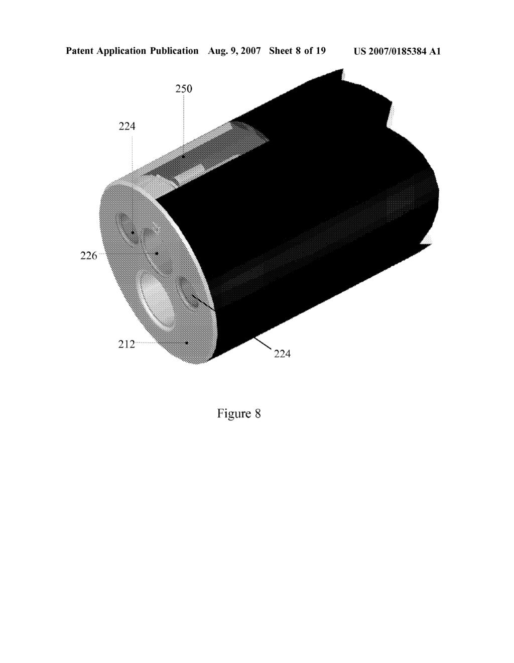
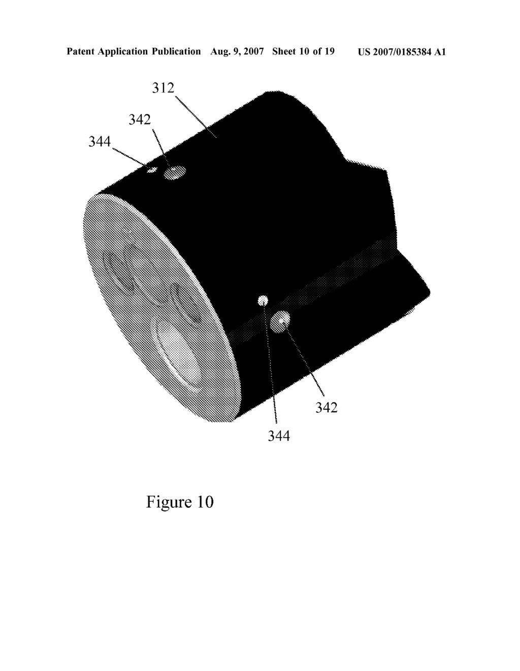
25 US 2007/ A1 Aug. 9, 2007 viewing imaging unit 70 allows more effective navigation of the endoscope 10. Additionally, to allow an accessory to reach the area in front of the secondary imaging device 30, the secondary imaging device 30 may be configured so as not to obstruct one or more channels 22 of the insertion tube 12. For example, the secondary imaging device 30 may be made Small enough so that it does not obstruct the channel 22 of the insertion tube 12. Alternatively, the secondary imaging device 30 may include a through hole (not shown) aligned with the channel 22 of the insertion tube 12. This through hole allows an accessory to reach the area in front of the secondary imaging device In accordance with further embodiments of the present invention, the secondary imaging device may have the two imaging units 42, 70, one on the proximal side of the secondary imaging device and the other on the distal side of the secondary imaging device, but the insertion tube 12 does not have the main imaging device 26. The increased space on the distal end of the insertion tube 12 can be used to provide one or more additional channels In another embodiment, the secondary imaging device 30 can be extended and retracted from the insertion tube 12. As shown in FIG. 6, the endoscope 10 may include a linear actuator 73 placed in an enclosure 75 and is connected to the link 36. The linear actuator 73 can extend the link 36 from a hollow guide 77 and retract the link 36 into the hollow guide 77. This allows the physician to retract the secondary imaging device 30 when advancing the endo scope 10 through a difficult region of the body, and then extend the secondary imaging device 30 when the endo scope 10 reaches its destination. Additionally, the extension and retraction of the secondary imaging device adjusts the distance between the main and secondary imaging devices In operation, the power may be turned on first to activate the imaging devices 26, 30 and the light sources At this point, the imaging devices 26, 30 begin trans mitting captured images to the external control box. The control box then processes the image signals and sends them to a display so that a medical professional can visualize the images in real time. At this point, the main imaging device 26 provides a front view of an area, while the secondary imaging device 30 provides a rear or retrograde view of the same area. During the medical procedure, the endoscope 10 is inserted into a patient. The medical professional can simultaneously visualize images from the main imaging device 26 and from the secondary imaging device 30. Lesions hidden from the main imaging device 26 behind folds and flexures can now be viewed by the medical professional from the images provided by the secondary imaging device 30. When the procedure is complete, the endoscope 10 is removed from the patient The external control box can be used to adjust the parameters of the imaging devices 26, 30 and light sources 24, 44 to achieve optimum image quality. During the pro cedure, relevant video and image data may be recorded in the patient s electronic medical records (EMR) file In accordance with another aspect of the invention, one or more rear-viewing imaging devices may be mounted in or on the distal end region of the insertion tube to provide retrograde views. FIGS. 7 and 8 illustrate an embodiment according to this aspect of the invention. In this embodi ment, in addition to the main imaging device 226 and main light sources 224 (FIG. 8), the endoscope 210 also includes two rear-viewing imaging devices 230 mounted inside the distal end region of the insertion tube 212, although the endoscope 210 may include any number of rear-viewing imaging devices. Each rear-viewing imaging device 230 includes an imaging unit 242 and a light source 244. The sheath 223 of the insertion tube 212 may have a window 250 for each of the rear-viewing imaging devices 230 to see through. In this embodiment, each window 255 forms a portion of the cylindrical sheath 223 and may be dimen sioned to maximize the field of view of the corresponding imaging device In this embodiment, the imaging devices 230 are mounted on the proximal side of the insertion tube's end cap 229, although the rear-viewing imaging devices 230 may be mounted on any suitable structure of the insertion tube 212, Such as shown in FIG. 11. Each of the rear-viewing imaging devices 230 is positioned to face a direction that is prefer ably within or equal to 90 from the longitudinal axis of the insertion tube 212, more preferably within or equal to 45 from the longitudinal axis of the insertion tube 212. Pref erably, the direction that each rear-viewing imaging device 30 faces is optimized to provide the rear-viewing imaging device 30 with the largest field of view In addition to the embodiment shown in FIGS. 7 and 8, this aspect of the invention may have additional variations. For example, FIG. 9 illustrates an embodiment 310, in which the rear-viewing imaging devices 330 are mounted at a 90 angle from the longitudinal axis of the insertion tube 312. Each imaging device 330 includes an imaging unit 342 and a light source 344. Each rear-viewing imaging device 330 may be provided with a window, as shown in FIG. 8, or they may protrude from the sheath 323 as shown in FIG. 10. The rear-viewing imaging device 330 may be mounted on the proximal side of the insertion tube's end cap 329, as shown in FIG.9, or on any suitable structure of the insertion tube 312, such as shown in FIG FIGS. 11 and 12 illustrate additional embodiments 410,510 according to this aspect of the invention. In each of these embodiments 410,510, an insertion tube 412, 512 has a circular groove 477, 577 with a front-facing sidewall 479, 579 and a rear-facing sidewall 481,581. In the embodiment 410 shown in FIG. 11, the windows for the rear-viewing imaging devices 430 installed insdie the insertion tube 412 are provided on the rear-facing sidewall 481 of the groove 477. In the embodiment 510 shown in FIG. 12, the imaging units 542 protrude from the rear-facing sidewall 581 of the groove FIG. 13 illustrates a further embodiment 610 according to this aspect of the invention. In this embodiment 610, the insertion tube 612 includes a circular protrusion 677 that has a front-facing side 679 and a rear-facing side 681. In this embodiment, imaging devices 630 are provided on the rear-facing side 681 of the circular protrusion 677. In general, however, imaging devices may also be provided on the distal end, front-facing side 679 of the circular protrusion The image data received from the rear-facing imag ing devices may be combined to provide a 360 rear view. This may be accomplished by digitally combining or stitch ing the complementary images provided by individual rear-facing imaging devices into a single image. This may be

26 US 2007/ A1 Aug. 9, 2007 done using hardware and/or software tools well known in the image processing industry. The rear-facing imaging devices may be positioned so as to capture an entire 360 rear view with a certain amount of overlap between the fields of view of adjacent imaging devices. An algorithm that is run on a computing device in the control box or connected to the control box may be used to compare the image data from adjacent imaging devices for matching image patterns, which indicate image overlaps. Then the overlaps are elimi nated or reduced, and the images are combined to produce a single 360 rear image Alternatively, a number of display devices corre sponding to the number of rear viewing imaging devices may be provided. Each of the display devices may be used to display a distinct image from an imaging device. The display devices may be arranged in order, so as to simulate a continuous 360 view In accordance with a further aspect of the inven tion, an endoscope 710, as shown in FIG. 14, includes an insertion tube 712, a control handle 714 connected to the insertion tube 712, and an imaging device 730 extending from the distal end of the insertion tube ) The insertion tube 712 of this embodiment, as shown in FIG. 15, may be similar to the insertion tube 12 shown in FIG. 1. For example, the insertion tube 712 may be detachable from the control handle 714 or may be integrally formed with the control handle 714. The insertion tube 712 preferably has a longitudinal channel 722 through which an instrument can reach the body cavity to perform any desired procedures. Preferably, the distal end region 713 of the insertion tube 712 is steerable (FIG. 14), and control cables 718 (FIG. 15) may be used to steer the distal end region 713. In this embodiment, the insertion tube 712 does not have a main imaging device at its distal end, although it may have Such an imaging device in alternate embodiments. The insertion tube 712 may include a flexible ribbon coil 721 and a flexible sheath 723 that is used to protect the internal components of the insertion tube 712 from the environment of the body. An end cap 729 may be used to seal the open end of the shield 723 to close the distal end of the insertion tube As shown in FIG. 14, the control handle 714 may include one or more control knobs 716 that are attached to control cables 718 (FIG. 15) for the manipulation of the insertion tube 12. Preferably, the rotation of the control knobs 716 pulls the control cables 718 and therefore moves or bends the distal end region 713 of the insertion tube 712 up and down and/or side to side. Preferably, as shown in FIG. 14, the control handle 714 has one or more ports and/or valves 720. The ports and/or valves 720 are in communica tion with their respective channels 722 (FIG. 15) of the insertion tube 712. The ports and/or valves 720 can be air or water valves, suction valves, instrumentation ports, and Suction/instrumentation ports. The proximal end of the con trol handle 714 may include an accessory outlet 728 that provides fluid communication between the air, water and Suction channels and the pumps and related accessories. The same outlet or a different outlet can be used for electrical lines to light and imaging components at the distal end of the endoscope The imaging device 730 includes an extension 731 that extends from the distal end of the insertion tube 712, and one or more imaging units 750 and one or more light Sources 752 that are mounted in the distal end region of the extension 731. In the illustrated embodiment, the extension 731 has a tubular configuration, and its diameter is approximately a third of the insertion tube's diameter. Similar to the insertion tube 712, the extension 731 may have a ribbon coil and a flexible sheath. The electrical wires for the imaging unit 750 and light source 752 may be routed through a channel 725 in the extension 731. Alternatively, the imaging unit 750 may be a wireless unit as described in U.S. patent applica tion Ser. No. 1 1/609, In this embodiment, at least the distal end region of the extension 731 is steerable to increase the areas accessible to the imaging unit 750. The extension 731 may be steered in a manner similar to how the insertion tube 712 is steered, i.e. by using Bowden cables 733. The first ends of the Bowden cables 733 may be attached to the proximal end of the extension's end cap 735, and the second ends may be attached to controls 716 on the handle 714 (FIG. 14). Accordingly, the handle 714 has two sets of controls 716 to articulate the distal end regions of the insertion tube 12 and extension The distal end region of the extension 731 may be steered up to 45, 60, 90, 120, 150, or preferably 180 as shown in FIG. 16. The distal end region of the extension 731 may be steered in the direction of the channel 722 of the insertion tube 712 or in the direction of the axis of the insertion tube 712, and it may also be steered in the opposite direction. In other words, the distal end region of the extension 731 may be steered up to 180 in one direction and up to 180 in the opposite direction. In general, the distal end region may be steered in any number of directions, such as in only one direction or in three or more directions The imaging unit 750 may have an image sensor (not shown) and a lens assembly (not shown) with associ ated circuitry which is integrated on a PCB 754. As shown in FIG. 17, this PCB 754 preferably is attached to the proximal side of the extension's end cap 735. Data output, control and power lines for the imaging unit 750 can be fed to the proximal end of the endoscope 710 to be interfaced via the handle 714 to the control box. Any additional processing of the signals may be done in the control box and finally fed to a display device The lens assembly comprising the lens or multiple lenses in a housing can be mounted directly onto the PCB 754 such that it overlies the image sensor and focuses the light entering the lens system onto the photosensitive area of the image sensor The imaging units 750 and light sources 752 may be placed at any suitable location or locations in the distal end region of the extension 731. For example, as shown in FIG. 15, an imaging unit 750 and a light source 752 are placed on the distal end of the extension 731. Additionally or alternatively, as shown in FIG. 18, an imaging unit 750 and a light source 752 may be placed on a side of the distal end region of the extension 731. Furthermore, as shown in FIG. 19, imaging units 750 and light sources 752 may additionally or alternatively be placed on two opposite sides of the distal end region of the extension According to this aspect of the invention, both the extension 731 and the distal end region of the insertion tube

27 US 2007/ A1 Aug. 9, are steerable 180 in two directions. Consequently, the physician can better locate both the imaging unit 750 and the distal end of the insertion tube 712, resulting in a greater viewing field and allowing viewing of the areas behind folds and flexures. The steerable extension 731 is advantageous because it allows a greater degree of movement due to its Smaller diameter and greater flexibility as compared to the distal end region of the insertion tube While particular embodiments of the present invention have been shown and described, it will be obvious to those skilled in the art that changes and modifications can be made without departing from this invention in its broader aspects. Therefore, the appended claims are to encompass within their scope all such changes and modifications as fall within the true spirit and scope of this invention. 1. An endoscope comprising: an insertion tube having a distal end; and an imaging device including a steerable extension having a distal end and a proximal end, wherein the proximal end of the extension is attached to the distal end of the insertion tube. 2. The endoscope of claim 1, wherein the distal end of the steerable extension is steerable in one direction up to The endoscope of claim 1, wherein the distal end of the steerable extension is steerable in two opposite directions. 4. The endoscope of claim 3, wherein the distal end of the steerable extension is steerable up to 180 in each of the two opposite directions. 5. The endoscope of claim 1, wherein the distal end of the steerable extension is steerable in three or more directions. 6. The endoscope of claim 1, wherein the steerable extension has a diameter that is approximately a third of the insertion tube's diameter. 7. The endoscope of claim 1, wherein the distal end of the insertion tube is steerable. 8. The endoscope of claim 1, wherein the imaging device includes an imaging unit that is provided on the distal end of the steerable extension. 9. The endoscope of claim 1, wherein the imaging device includes an imaging unit that is provided on a side Surface of the distal end region of the steerable extension. 10. The endoscope of claim 1, wherein the imaging device includes two imaging units that are provided on the opposite sides of the distal end region of the steerable extension. 11. An endoscope comprising: an insertion tube having a distal end region; and a rear-viewing imaging device at least partially disposed inside the distal end region. 12. The endoscope of claim 11, wherein the insertion tube includes a sheath having a window placed in front of the rear-viewing imaging device. 13. The endoscope of claim 11, wherein the rear-viewing imaging device protrudes outside of the insertion tube. 14. The endoscope of claim 11, wherein the distal end region of the insertion tube includes a circular groove having a front-facing sidewall and rear-facing sidewall. 15. The endoscope of claim 14, wherein the rear-facing sidewall has a rear-viewing imaging device. 16. The endoscope of claim 14, wherein the rear-viewing imaging device protrudes outside of the rear-facing sidewall. 17. The endoscope of claim 11, wherein the distal end region of the insertion tube includes a circular protrusion having a front-facing side and rear-facing side. 18. The endoscope of claim 17, wherein the rear-facing side of the protrusion has a window placed in front of the rear-viewing imaging device. 19. The endoscope of claim 17, wherein the rear-viewing imaging device protrudes outside of the rear-facing side of the protrusion. 20. The endoscope of claim 11, further comprising a plurality of rear-viewing imaging devices, wherein imaging signals from the rear-viewing imaging devices are combined to provide an integrated rear view. 21. The endoscope of claim 20, wherein the integrated rear view is a 360 view. 22. An endoscope comprising: an insertion tube having a distal end region; a plurality of imaging elements, wherein at least one of the imaging elements is positioned on the distal end of the insertion tube, and wherein at least one of the imaging elements is positioned in the distal end region of the insertion tube behind (proximally) to the first imaging element on the distal region of the insertion tube 23. The endoscope of claim 22, wherein images from the imaging sensors are provided on a display device for simul taneous viewing 24. A method of viewing a lumen of the body comprising providing simultaneous viewing of images from front and rear viewing imaging elements attached to a single insertion tube. 25. An endoscope comprising: an insertion tube: a main imaging device positioned on a distal end of the insertion tube: a secondary imaging device; and an actuator, wherein the actuator extends the secondary imaging device out of, and retracts the secondary imaging device into, the insertion tube, and wherein the extension and retraction of the secondary imaging device adjusts the distance between the main and secondary imaging devices. 26. An endoscope comprising: an insertion tube having a distal end cap; an imaging device; and a link that couples the imaging device to the distal end cap of the insertion tube, wherein the imaging device includes a housing element, and wherein the housing element, link and distal end cap form a unitary unit. 27. An endoscope comprising: an insertion tube having a distal end cap; a main imaging device positioned on a distal end of the insertion tube: a secondary imaging device; and a link that couples the secondary imaging device to the distal end cap of the insertion tube, wherein the main and secondary imaging devices provide different views of the same area.
28 US 2007/ A1 Aug. 9, An endoscope comprising: an insertion tube having a distal end cap; a main imaging device including a main light source, the main imaging device being positioned on a distal end of the insertion tube: a secondary imaging device including a secondary light Source; and a link that couples the secondary imaging device to the distal end cap of the insertion tube, wherein the main and secondary imaging devices and their light sources are turned on and off alternately to reduce or eliminate light interference. 29. The endoscope of claim 28, wherein the main and secondary imaging devices and their light sources are turned on and off at a sufficiently high frequency Such that eyes do not sense that the main and secondary imaging devices and their light sources are intermittently turned on and off. 30. An endoscope comprising: an insertion tube having a distal end cap; a main imaging device including a main light source, the main imaging device being positioned on a distal end of the insertion tube: a secondary imaging device including a secondary light Source; and a link that couples the secondary imaging device to the distal end cap of the insertion tube, wherein the main imaging device and main light source are covered by a first set of polarizer filters of the same orientation, and wherein the secondary imaging device and secondary light Source are covered by a second set of polarizer filters orientated at 90 relative to the first set of polarizer filters. 31. An endoscope comprising: an insertion tube having a distal end cap; a main imaging device including a main light Source, the main imaging device being positioned on a distal end of the insertion tube: a secondary imaging device including a secondary light Source; and a link that couples the secondary imaging device to the distal end cap of the insertion tube, wherein only one of the imaging devices is covered by a first polarizer filter, and only the other light Source is covered by a second polarizer filter orientated at 90 relative to the first polarizer filter.
(12) Patent Application Publication (10) Pub. No.: US 2007/ A1
 Patent Application Publication (10) Pub. No.: US 2007/ A1") (19) United States (12) Patent Application Publication (10) Pub. No.: US 2007/0132875 A1 Lee et al. US 20070132875A1 (43) Pub. Date: Jun. 14, 2007 (54) (75) (73) (21) (22) (30) OPTICAL LENS SYSTEM OF MOBILE
(19) United States (12) Patent Application Publication (10) Pub. No.: US 2007/0132875 A1 Lee et al. US 20070132875A1 (43) Pub. Date: Jun. 14, 2007 (54) (75) (73) (21) (22) (30) OPTICAL LENS SYSTEM OF MOBILE
(12) Patent Application Publication (10) Pub. No.: US 2006/ A1
 Patent Application Publication (10) Pub. No.: US 2006/ A1") US 2006004.4273A1 (19) United States (12) Patent Application Publication (10) Pub. No.: US 2006/0044273 A1 Numazawa et al. (43) Pub. Date: Mar. 2, 2006 (54) MOUSE-TYPE INPUT DEVICE (30) Foreign Application
US 2006004.4273A1 (19) United States (12) Patent Application Publication (10) Pub. No.: US 2006/0044273 A1 Numazawa et al. (43) Pub. Date: Mar. 2, 2006 (54) MOUSE-TYPE INPUT DEVICE (30) Foreign Application
(12) Patent Application Publication (10) Pub. No.: US 2007/ A1
 Patent Application Publication (10) Pub. No.: US 2007/ A1") (19) United States US 20070147825A1 (12) Patent Application Publication (10) Pub. No.: US 2007/0147825 A1 Lee et al. (43) Pub. Date: Jun. 28, 2007 (54) OPTICAL LENS SYSTEM OF MOBILE Publication Classification
(19) United States US 20070147825A1 (12) Patent Application Publication (10) Pub. No.: US 2007/0147825 A1 Lee et al. (43) Pub. Date: Jun. 28, 2007 (54) OPTICAL LENS SYSTEM OF MOBILE Publication Classification
(12) Patent Application Publication (10) Pub. No.: US 2003/ A1
 Patent Application Publication (10) Pub. No.: US 2003/ A1") US 20030091084A1 (19) United States (12) Patent Application Publication (10) Pub. No.: US 2003/0091084A1 Sun et al. (43) Pub. Date: May 15, 2003 (54) INTEGRATION OF VCSEL ARRAY AND Publication Classification
US 20030091084A1 (19) United States (12) Patent Application Publication (10) Pub. No.: US 2003/0091084A1 Sun et al. (43) Pub. Date: May 15, 2003 (54) INTEGRATION OF VCSEL ARRAY AND Publication Classification
(12) Patent Application Publication (10) Pub. No.: US 2007/ A1
 Patent Application Publication (10) Pub. No.: US 2007/ A1") (19) United States US 20070185.506A1 (12) Patent Application Publication (10) Pub. No.: US 2007/0185.506 A1 JacksOn (43) Pub. Date: Aug. 9, 2007 (54) (76) (21) (22) (60) MEDICAL INSTRUMENTS AND METHODS
(19) United States US 20070185.506A1 (12) Patent Application Publication (10) Pub. No.: US 2007/0185.506 A1 JacksOn (43) Pub. Date: Aug. 9, 2007 (54) (76) (21) (22) (60) MEDICAL INSTRUMENTS AND METHODS
(12) United States Patent (10) Patent No.: US 8,187,032 B1
 United States Patent (10) Patent No.: US 8,187,032 B1") US008187032B1 (12) United States Patent (10) Patent No.: US 8,187,032 B1 Park et al. (45) Date of Patent: May 29, 2012 (54) GUIDED MISSILE/LAUNCHER TEST SET (58) Field of Classification Search... 439/76.1.
US008187032B1 (12) United States Patent (10) Patent No.: US 8,187,032 B1 Park et al. (45) Date of Patent: May 29, 2012 (54) GUIDED MISSILE/LAUNCHER TEST SET (58) Field of Classification Search... 439/76.1.
(12) Patent Application Publication (10) Pub. No.: US 2003/ A1
 Patent Application Publication (10) Pub. No.: US 2003/ A1") (19) United States (12) Patent Application Publication (10) Pub. No.: US 2003/0062354 A1 Ward US 2003.0062354A1 (43) Pub. Date: (54) (76) (21) (22) (60) (51) (52) WIRE FEED SPEED ADJUSTABLE WELDING TORCH
(19) United States (12) Patent Application Publication (10) Pub. No.: US 2003/0062354 A1 Ward US 2003.0062354A1 (43) Pub. Date: (54) (76) (21) (22) (60) (51) (52) WIRE FEED SPEED ADJUSTABLE WELDING TORCH
(12) Patent Application Publication (10) Pub. No.: US 2003/ A1
 Patent Application Publication (10) Pub. No.: US 2003/ A1") US 20030085640A1 (19) United States (12) Patent Application Publication (10) Pub. No.: US 2003/0085640 A1 Chan (43) Pub. Date: May 8, 2003 (54) FOLDABLE CABINET Publication Classification (76) Inventor:
US 20030085640A1 (19) United States (12) Patent Application Publication (10) Pub. No.: US 2003/0085640 A1 Chan (43) Pub. Date: May 8, 2003 (54) FOLDABLE CABINET Publication Classification (76) Inventor:
Ayuekanbe Atagabe. Physics 464(applied Optics) Winter Project Report. Fiber Optics in Medicine. March 11, 2003
 Winter Project Report. Fiber Optics in Medicine. March 11, 2003") Ayuekanbe Atagabe Physics 464(applied Optics) Winter 2003 Project Report Fiber Optics in Medicine March 11, 2003 Abstract: Fiber optics have become very important in medical diagnoses in this modern era
Ayuekanbe Atagabe Physics 464(applied Optics) Winter 2003 Project Report Fiber Optics in Medicine March 11, 2003 Abstract: Fiber optics have become very important in medical diagnoses in this modern era
(12) Patent Application Publication (10) Pub. No.: US 2015/ A1
 Patent Application Publication (10) Pub. No.: US 2015/ A1") (19) United States US 2015O108945A1 (12) Patent Application Publication (10) Pub. No.: US 2015/0108945 A1 YAN et al. (43) Pub. Date: Apr. 23, 2015 (54) DEVICE FOR WIRELESS CHARGING (52) U.S. Cl. CIRCUIT
(19) United States US 2015O108945A1 (12) Patent Application Publication (10) Pub. No.: US 2015/0108945 A1 YAN et al. (43) Pub. Date: Apr. 23, 2015 (54) DEVICE FOR WIRELESS CHARGING (52) U.S. Cl. CIRCUIT
(12) Patent Application Publication (10) Pub. No.: US 2010/ A1
 Patent Application Publication (10) Pub. No.: US 2010/ A1") US 20100063451A1 (19) United States (12) Patent Application Publication (10) Pub. No.: US 2010/0063451 A1 Gray et al. (43) Pub. Date: Mar. 11, 2010 (54) POWER INJECTABLE PORT Publication Classification
US 20100063451A1 (19) United States (12) Patent Application Publication (10) Pub. No.: US 2010/0063451 A1 Gray et al. (43) Pub. Date: Mar. 11, 2010 (54) POWER INJECTABLE PORT Publication Classification
United States Patent (19)
") United States Patent (19) Ogawa 11 Patent Number: 45 Date of Patent: Jan. 30, 1990 54 ENDOSCOPICTREATING TOOL 75) Inventor: 73) Assignee: Mototsugu Ogawa, Hachioji, Japan Olympus Optical Co., Ltd., Tokyo,
United States Patent (19) Ogawa 11 Patent Number: 45 Date of Patent: Jan. 30, 1990 54 ENDOSCOPICTREATING TOOL 75) Inventor: 73) Assignee: Mototsugu Ogawa, Hachioji, Japan Olympus Optical Co., Ltd., Tokyo,
(12) Patent Application Publication (10) Pub. No.: US 2012/ A1
 Patent Application Publication (10) Pub. No.: US 2012/ A1") (19) United States US 20120202410A1 (12) Patent Application Publication (10) Pub. No.: US 2012/0202410 A1 Byers (43) Pub. Date: Aug. 9, 2012 54) SHARPENING TOOL Publication Classification (76) Inventor:
(19) United States US 20120202410A1 (12) Patent Application Publication (10) Pub. No.: US 2012/0202410 A1 Byers (43) Pub. Date: Aug. 9, 2012 54) SHARPENING TOOL Publication Classification (76) Inventor:
United States Patent to 11 3,998,002
 United States Patent to 11 Nathanson 45 Dec. 21, 1976 54 PANEL, HOLDER FOR SMALL STRUCTURES AND TOYS 76 Inventor: Albert Nathanson, 249-26 63rd Ave., Little Neck, N.Y. 11329 22 Filed: Jan. 29, 1975 (21
(12) Patent Application Publication (10) Pub. No.: US 2012/ A1. Johnson (43) Pub. Date: Jan. 5, 2012
 Patent Application Publication (10) Pub. No.: US 2012/ A1. Johnson (43) Pub. Date: Jan. 5, 2012") (19) United States US 20120000970A1 (12) Patent Application Publication (10) Pub. No.: US 2012/0000970 A1 Johnson (43) Pub. Date: Jan. 5, 2012 (54) GIFTWRAP WITH TAPE (52) U.S. Cl.... 229/87.19; 428/42.3:40/638;
(19) United States US 20120000970A1 (12) Patent Application Publication (10) Pub. No.: US 2012/0000970 A1 Johnson (43) Pub. Date: Jan. 5, 2012 (54) GIFTWRAP WITH TAPE (52) U.S. Cl.... 229/87.19; 428/42.3:40/638;
(12) United States Patent (10) Patent No.: US 7,156,854 B2
 United States Patent (10) Patent No.: US 7,156,854 B2") US007 156854B2 (12) United States Patent (10) Patent No.: US 7,156,854 B2 BrOWn et al. (45) Date of Patent: Jan. 2, 2007 (54) LENS DELIVERY SYSTEM 5,944,725 A * 8/1999 Cicenas et al.... 606/107 6,241,737
US007 156854B2 (12) United States Patent (10) Patent No.: US 7,156,854 B2 BrOWn et al. (45) Date of Patent: Jan. 2, 2007 (54) LENS DELIVERY SYSTEM 5,944,725 A * 8/1999 Cicenas et al.... 606/107 6,241,737
(12) Patent Application Publication (10) Pub. No.: US 2013/ A1
 Patent Application Publication (10) Pub. No.: US 2013/ A1") (19) United States US 2013 0307772A1 (12) Patent Application Publication (10) Pub. No.: US 2013/0307772 A1 WU (43) Pub. Date: Nov. 21, 2013 (54) INTERACTIVE PROJECTION SYSTEM WITH (52) U.S. Cl. LIGHT SPOT
(19) United States US 2013 0307772A1 (12) Patent Application Publication (10) Pub. No.: US 2013/0307772 A1 WU (43) Pub. Date: Nov. 21, 2013 (54) INTERACTIVE PROJECTION SYSTEM WITH (52) U.S. Cl. LIGHT SPOT
(12) Patent Application Publication (10) Pub. No.: US 2011/ A1
 Patent Application Publication (10) Pub. No.: US 2011/ A1") (19) United States (12) Patent Application Publication (10) Pub. No.: US 2011/0308807 A1 Spencer US 2011 0308807A1 (43) Pub. Date: Dec. 22, 2011 (54) (75) (73) (21) (22) (60) USE OF WIRED TUBULARS FOR
(19) United States (12) Patent Application Publication (10) Pub. No.: US 2011/0308807 A1 Spencer US 2011 0308807A1 (43) Pub. Date: Dec. 22, 2011 (54) (75) (73) (21) (22) (60) USE OF WIRED TUBULARS FOR
(12) United States Patent
 United States Patent") US008133074B1 (12) United States Patent Park et al. (10) Patent No.: (45) Date of Patent: Mar. 13, 2012 (54) (75) (73) (*) (21) (22) (51) (52) GUIDED MISSILE/LAUNCHER TEST SET REPROGRAMMING INTERFACE ASSEMBLY
US008133074B1 (12) United States Patent Park et al. (10) Patent No.: (45) Date of Patent: Mar. 13, 2012 (54) (75) (73) (*) (21) (22) (51) (52) GUIDED MISSILE/LAUNCHER TEST SET REPROGRAMMING INTERFACE ASSEMBLY
(12) Patent Application Publication (10) Pub. No.: US 2002/ A1
 Patent Application Publication (10) Pub. No.: US 2002/ A1") US 20020046661A1 (19) United States (12) Patent Application Publication (10) Pub. No.: US 2002/0046661 A1 Hawkins (43) Pub. Date: Apr. 25, 2002 (54) HYDRAULIC PRESS (52) U.S. Cl.... 100/269.17 (76) Inventor:
US 20020046661A1 (19) United States (12) Patent Application Publication (10) Pub. No.: US 2002/0046661 A1 Hawkins (43) Pub. Date: Apr. 25, 2002 (54) HYDRAULIC PRESS (52) U.S. Cl.... 100/269.17 (76) Inventor:
(2) Patent Application Publication (10) Pub. No.: US 2016/ A1
 Patent Application Publication (10) Pub. No.: US 2016/ A1") (19) United States (2) Patent Application Publication (10) Pub. No.: Scapa et al. US 20160302277A1 (43) Pub. Date: (54) (71) (72) (21) (22) (63) LIGHT AND LIGHT SENSOR Applicant; ilumisys, Inc., Troy,
(19) United States (2) Patent Application Publication (10) Pub. No.: Scapa et al. US 20160302277A1 (43) Pub. Date: (54) (71) (72) (21) (22) (63) LIGHT AND LIGHT SENSOR Applicant; ilumisys, Inc., Troy,
(12) (10) Patent No.: US 8,083,443 B1. Circosta et al. 45) Date of Patent: Dec. 27, 2011
 (10) Patent No.: US 8,083,443 B1. Circosta et al. 45) Date of Patent: Dec. 27, 2011") United States Patent USOO8083443B1 (12) (10) Patent No.: US 8,083,443 B1 Circosta et al. 45) Date of Patent: Dec. 27, 2011 9 (54) POCKET HOLE PLUG CUTTER 5,800,099 A * 9/1998 Cooper... 408.1 R 5,807,036
United States Patent USOO8083443B1 (12) (10) Patent No.: US 8,083,443 B1 Circosta et al. 45) Date of Patent: Dec. 27, 2011 9 (54) POCKET HOLE PLUG CUTTER 5,800,099 A * 9/1998 Cooper... 408.1 R 5,807,036
(12) Patent Application Publication (10) Pub. No.: US 2012/ A1
 Patent Application Publication (10) Pub. No.: US 2012/ A1") US 20120047754A1 (19) United States (12) Patent Application Publication (10) Pub. No.: US 2012/0047754 A1 Schmitt (43) Pub. Date: Mar. 1, 2012 (54) ELECTRICSHAVER (52) U.S. Cl.... 30/527 (57) ABSTRACT
US 20120047754A1 (19) United States (12) Patent Application Publication (10) Pub. No.: US 2012/0047754 A1 Schmitt (43) Pub. Date: Mar. 1, 2012 (54) ELECTRICSHAVER (52) U.S. Cl.... 30/527 (57) ABSTRACT
(12) Patent Application Publication (10) Pub. No.: US 2006/ A1
 Patent Application Publication (10) Pub. No.: US 2006/ A1") US 20060239744A1 (19) United States (12) Patent Application Publication (10) Pub. No.: US 2006/0239744 A1 Hideaki (43) Pub. Date: Oct. 26, 2006 (54) THERMAL TRANSFERTYPE IMAGE Publication Classification
US 20060239744A1 (19) United States (12) Patent Application Publication (10) Pub. No.: US 2006/0239744 A1 Hideaki (43) Pub. Date: Oct. 26, 2006 (54) THERMAL TRANSFERTYPE IMAGE Publication Classification
(12) United States Patent
 United States Patent") US00795.5254B2 (12) United States Patent Hanke (10) Patent No.: (45) Date of Patent: Jun. 7, 2011 (54) MEDICAL VIDEOSCOPE WITH A PIVOTABLY ADJUSTABLE END PART (75) Inventor: Harald Hanke, Hamburg (DE)
US00795.5254B2 (12) United States Patent Hanke (10) Patent No.: (45) Date of Patent: Jun. 7, 2011 (54) MEDICAL VIDEOSCOPE WITH A PIVOTABLY ADJUSTABLE END PART (75) Inventor: Harald Hanke, Hamburg (DE)
(12) Patent Application Publication (10) Pub. No.: US 2005/ A1
 Patent Application Publication (10) Pub. No.: US 2005/ A1") US 2005O277913A1 (19) United States (12) Patent Application Publication (10) Pub. No.: US 2005/0277913 A1 McCary (43) Pub. Date: Dec. 15, 2005 (54) HEADS-UP DISPLAY FOR DISPLAYING Publication Classification
US 2005O277913A1 (19) United States (12) Patent Application Publication (10) Pub. No.: US 2005/0277913 A1 McCary (43) Pub. Date: Dec. 15, 2005 (54) HEADS-UP DISPLAY FOR DISPLAYING Publication Classification
(12) Patent Application Publication (10) Pub. No.: US 2004/ A1
 Patent Application Publication (10) Pub. No.: US 2004/ A1") US 2004.0060551A1 (19) United States (12) Patent Application Publication (10) Pub. No.: US 2004/0060551A1 Gallops, JR. (43) Pub. Date: Apr. 1, 2004 (54) METHOD FOR MANUFACTURING (21) Appl. No.: 10/255.287
US 2004.0060551A1 (19) United States (12) Patent Application Publication (10) Pub. No.: US 2004/0060551A1 Gallops, JR. (43) Pub. Date: Apr. 1, 2004 (54) METHOD FOR MANUFACTURING (21) Appl. No.: 10/255.287
(12) United States Patent (10) Patent No.: US 6,663,057 B2
 United States Patent (10) Patent No.: US 6,663,057 B2") USOO6663057B2 (12) United States Patent (10) Patent No.: US 6,663,057 B2 Garelick et al. (45) Date of Patent: Dec. 16, 2003 (54) ADJUSTABLE PEDESTAL FOR BOAT 5,297.849 A * 3/1994 Chancellor... 297/344.
USOO6663057B2 (12) United States Patent (10) Patent No.: US 6,663,057 B2 Garelick et al. (45) Date of Patent: Dec. 16, 2003 (54) ADJUSTABLE PEDESTAL FOR BOAT 5,297.849 A * 3/1994 Chancellor... 297/344.
(12) Patent Application Publication (10) Pub. No.: US 2001/ A1
 Patent Application Publication (10) Pub. No.: US 2001/ A1") US 2001 0004 175A1 (19) United States (12) Patent Application Publication (10) Pub. No.: US 2001/0004175 A1 Kelleher (43) Pub. Date: Jun. 21, 2001 (54) GENERATOR STATOR SLOT WEDGE Related U.S. Application
US 2001 0004 175A1 (19) United States (12) Patent Application Publication (10) Pub. No.: US 2001/0004175 A1 Kelleher (43) Pub. Date: Jun. 21, 2001 (54) GENERATOR STATOR SLOT WEDGE Related U.S. Application
(12) United States Patent
 United States Patent") (12) United States Patent USOO867761 OB2 (10) Patent No.: US 8,677,610 B2 Liu (45) Date of Patent: Mar. 25, 2014 (54) CRIMPING TOOL (56) References Cited (75) Inventor: Jen Kai Liu, New Taipei (TW) U.S.
(12) United States Patent USOO867761 OB2 (10) Patent No.: US 8,677,610 B2 Liu (45) Date of Patent: Mar. 25, 2014 (54) CRIMPING TOOL (56) References Cited (75) Inventor: Jen Kai Liu, New Taipei (TW) U.S.
(12) United States Patent (10) Patent No.: US 6,752,496 B2
 United States Patent (10) Patent No.: US 6,752,496 B2") USOO6752496 B2 (12) United States Patent (10) Patent No.: US 6,752,496 B2 Conner (45) Date of Patent: Jun. 22, 2004 (54) PLASTIC FOLDING AND TELESCOPING 5,929.966 A * 7/1999 Conner... 351/118 EYEGLASS
USOO6752496 B2 (12) United States Patent (10) Patent No.: US 6,752,496 B2 Conner (45) Date of Patent: Jun. 22, 2004 (54) PLASTIC FOLDING AND TELESCOPING 5,929.966 A * 7/1999 Conner... 351/118 EYEGLASS
Endoscopic Ultrasonography System
 Endoscopic Ultrasonic Processor SU- -H-, SU- -S- Power rating Power supply rating Current consumption(rated) Dimensions Size Weight Ultrasonography Probe types image display Scanning modes Special modes*
(12) Patent Application Publication (10) Pub. No.: US 2004/ A1
 Patent Application Publication (10) Pub. No.: US 2004/ A1") (19) United States US 2004O142601A1 (12) Patent Application Publication (10) Pub. No.: US 2004/0142601 A1 Luu (43) Pub. Date: Jul. 22, 2004 (54) ADAPTER WALL PLATE ASSEMBLY WITH INTEGRATED ELECTRICAL FUNCTION
(19) United States US 2004O142601A1 (12) Patent Application Publication (10) Pub. No.: US 2004/0142601 A1 Luu (43) Pub. Date: Jul. 22, 2004 (54) ADAPTER WALL PLATE ASSEMBLY WITH INTEGRATED ELECTRICAL FUNCTION
United States Patent Fischell et al.
 United States Patent Fischell et al. 19 US006006124A 11 Patent Number: 6,006,124 (45) Date of Patent: Dec. 21, 1999 54 (75) MEANS AND METHOD FOR THE PLACEMENT OF BRAIN ELECTRODES Inventors: Robert E. Fischell,
(12) Patent Application Publication (10) Pub. No.: US 2008/ A1. Kalevo (43) Pub. Date: Mar. 27, 2008
 Patent Application Publication (10) Pub. No.: US 2008/ A1. Kalevo (43) Pub. Date: Mar. 27, 2008") US 2008.0075354A1 (19) United States (12) Patent Application Publication (10) Pub. No.: US 2008/0075354 A1 Kalevo (43) Pub. Date: (54) REMOVING SINGLET AND COUPLET (22) Filed: Sep. 25, 2006 DEFECTS FROM
US 2008.0075354A1 (19) United States (12) Patent Application Publication (10) Pub. No.: US 2008/0075354 A1 Kalevo (43) Pub. Date: (54) REMOVING SINGLET AND COUPLET (22) Filed: Sep. 25, 2006 DEFECTS FROM
United States Patent (19)
") United States Patent (19) Jirgens et al. 54 on ETRIP WINDOW. CUTTING TOOL METHOD AND APPARATUS (75) Inventors: Rainer Jirgens; Dietmar Krehl, both of Celle, Fed. Rep. of Germany 73) Assignee: Baker Hughes
United States Patent (19) Jirgens et al. 54 on ETRIP WINDOW. CUTTING TOOL METHOD AND APPARATUS (75) Inventors: Rainer Jirgens; Dietmar Krehl, both of Celle, Fed. Rep. of Germany 73) Assignee: Baker Hughes
(12) Patent Application Publication (10) Pub. No.: US 2001/ A1
 Patent Application Publication (10) Pub. No.: US 2001/ A1") US 2001 004.8356A1 (19) United States (12) Patent Application Publication (10) Pub. No.: US 2001/0048356A1 Owen (43) Pub. Date: Dec. 6, 2001 (54) METHOD AND APPARATUS FOR Related U.S. Application Data
US 2001 004.8356A1 (19) United States (12) Patent Application Publication (10) Pub. No.: US 2001/0048356A1 Owen (43) Pub. Date: Dec. 6, 2001 (54) METHOD AND APPARATUS FOR Related U.S. Application Data
(12) United States Patent
 United States Patent") (12) United States Patent US007.961391 B2 (10) Patent No.: US 7.961,391 B2 Hua (45) Date of Patent: Jun. 14, 2011 (54) FREE SPACE ISOLATOR OPTICAL ELEMENT FIXTURE (56) References Cited U.S. PATENT DOCUMENTS
(12) United States Patent US007.961391 B2 (10) Patent No.: US 7.961,391 B2 Hua (45) Date of Patent: Jun. 14, 2011 (54) FREE SPACE ISOLATOR OPTICAL ELEMENT FIXTURE (56) References Cited U.S. PATENT DOCUMENTS
(12) Patent Application Publication (10) Pub. No.: US 2009/ A1. Yoshizawa et al. (43) Pub. Date: Mar. 5, 2009
 Patent Application Publication (10) Pub. No.: US 2009/ A1. Yoshizawa et al. (43) Pub. Date: Mar. 5, 2009") (19) United States US 20090059759A1 (12) Patent Application Publication (10) Pub. No.: US 2009/0059759 A1 Yoshizawa et al. (43) Pub. Date: Mar. 5, 2009 (54) TRANSMISSIVE OPTICAL RECORDING (22) Filed: Apr.
(19) United States US 20090059759A1 (12) Patent Application Publication (10) Pub. No.: US 2009/0059759 A1 Yoshizawa et al. (43) Pub. Date: Mar. 5, 2009 (54) TRANSMISSIVE OPTICAL RECORDING (22) Filed: Apr.
(12) Patent Application Publication (10) Pub. No.: US 2012/ A1
 Patent Application Publication (10) Pub. No.: US 2012/ A1") (19) United States (12) Patent Application Publication (10) Pub. No.: US 2012/0103923 A1 Mansor et al. US 2012O103923A1 (43) Pub. Date: May 3, 2012 (54) (76) (21) (22) (63) (60) RAIL CONNECTOR FORMODULAR
(19) United States (12) Patent Application Publication (10) Pub. No.: US 2012/0103923 A1 Mansor et al. US 2012O103923A1 (43) Pub. Date: May 3, 2012 (54) (76) (21) (22) (63) (60) RAIL CONNECTOR FORMODULAR
(12) Patent Application Publication (10) Pub. No.: US 2015/ A1
 Patent Application Publication (10) Pub. No.: US 2015/ A1") (19) United States US 2015 0311941A1 (12) Patent Application Publication (10) Pub. No.: US 2015/0311941 A1 Sorrentino (43) Pub. Date: Oct. 29, 2015 (54) MOBILE DEVICE CASE WITH MOVABLE Publication Classification
(19) United States US 2015 0311941A1 (12) Patent Application Publication (10) Pub. No.: US 2015/0311941 A1 Sorrentino (43) Pub. Date: Oct. 29, 2015 (54) MOBILE DEVICE CASE WITH MOVABLE Publication Classification
System and method for focusing a digital camera
 Page 1 of 12 ( 8 of 32 ) United States Patent Application 20060103754 Kind Code A1 Wenstrand; John S. ; et al. May 18, 2006 System and method for focusing a digital camera Abstract A method of focusing
(12) United States Patent (10) Patent No.: US 6,224,230 B1
 United States Patent (10) Patent No.: US 6,224,230 B1") USOO622423OB1 (12) United States Patent (10) Patent No.: US 6,224,230 B1 Roegiers (45) Date of Patent: May 1, 2001 (54) ORNAMENT LIGHTING APPARATUS 3,655,495 4/1972 Carrell... 161/16 3,694,648 * 9/1972
USOO622423OB1 (12) United States Patent (10) Patent No.: US 6,224,230 B1 Roegiers (45) Date of Patent: May 1, 2001 (54) ORNAMENT LIGHTING APPARATUS 3,655,495 4/1972 Carrell... 161/16 3,694,648 * 9/1972
Y 6a W SES. (12) Patent Application Publication (10) Pub. No.: US 2005/ A1. (19) United States. Belinda et al. (43) Pub. Date: Nov.
 Patent Application Publication (10) Pub. No.: US 2005/ A1. (19) United States. Belinda et al. (43) Pub. Date: Nov.") (19) United States US 2005O2521.52A1 (12) Patent Application Publication (10) Pub. No.: Belinda et al. (43) Pub. Date: Nov. 17, 2005 (54) STEELTRUSS FASTENERS FOR MULTI-POSITIONAL INSTALLATION (76) Inventors:
(19) United States US 2005O2521.52A1 (12) Patent Application Publication (10) Pub. No.: Belinda et al. (43) Pub. Date: Nov. 17, 2005 (54) STEELTRUSS FASTENERS FOR MULTI-POSITIONAL INSTALLATION (76) Inventors:
\ Y 4-7. (12) Patent Application Publication (10) Pub. No.: US 2006/ A1. (19) United States. de La Chapelle et al. (43) Pub. Date: Nov.
 Patent Application Publication (10) Pub. No.: US 2006/ A1. (19) United States. de La Chapelle et al. (43) Pub. Date: Nov.") (19) United States US 2006027.0354A1 (12) Patent Application Publication (10) Pub. No.: US 2006/0270354 A1 de La Chapelle et al. (43) Pub. Date: (54) RF SIGNAL FEED THROUGH METHOD AND APPARATUS FOR SHIELDED
(19) United States US 2006027.0354A1 (12) Patent Application Publication (10) Pub. No.: US 2006/0270354 A1 de La Chapelle et al. (43) Pub. Date: (54) RF SIGNAL FEED THROUGH METHOD AND APPARATUS FOR SHIELDED
(12) Patent Application Publication (10) Pub. No.: US 2009/ A1
 Patent Application Publication (10) Pub. No.: US 2009/ A1") (19) United States US 20090249965A1 (12) Patent Application Publication (10) Pub. No.: US 2009/0249965 A1 Hauser (43) Pub. Date: (54) PIT REMOVER (75) Inventor: Lawrence M. Hauser, Auburn, WA (US) Correspondence
(19) United States US 20090249965A1 (12) Patent Application Publication (10) Pub. No.: US 2009/0249965 A1 Hauser (43) Pub. Date: (54) PIT REMOVER (75) Inventor: Lawrence M. Hauser, Auburn, WA (US) Correspondence
(12) United States Patent (10) Patent No.: US 6,436,044 B1
 United States Patent (10) Patent No.: US 6,436,044 B1") USOO643604.4B1 (12) United States Patent (10) Patent No.: Wang (45) Date of Patent: Aug. 20, 2002 (54) SYSTEM AND METHOD FOR ADAPTIVE 6,282,963 B1 9/2001 Haider... 73/602 BEAMFORMER APODIZATION 6,312,384
USOO643604.4B1 (12) United States Patent (10) Patent No.: Wang (45) Date of Patent: Aug. 20, 2002 (54) SYSTEM AND METHOD FOR ADAPTIVE 6,282,963 B1 9/2001 Haider... 73/602 BEAMFORMER APODIZATION 6,312,384
(12) Patent Application Publication (10) Pub. No.: US 2005/ A1
 Patent Application Publication (10) Pub. No.: US 2005/ A1") US 20050207013A1 (19) United States (12) Patent Application Publication (10) Pub. No.: US 2005/0207013 A1 Kanno et al. (43) Pub. Date: Sep. 22, 2005 (54) PHOTOELECTRIC ENCODER AND (30) Foreign Application
US 20050207013A1 (19) United States (12) Patent Application Publication (10) Pub. No.: US 2005/0207013 A1 Kanno et al. (43) Pub. Date: Sep. 22, 2005 (54) PHOTOELECTRIC ENCODER AND (30) Foreign Application
(12) Patent Application Publication (10) Pub. No.: US 2013/ A1
 Patent Application Publication (10) Pub. No.: US 2013/ A1") US 2013 0334265A1 (19) United States (12) Patent Application Publication (10) Pub. No.: US 2013/0334265 A1 AVis0n et al. (43) Pub. Date: Dec. 19, 2013 (54) BRASTORAGE DEVICE Publication Classification
US 2013 0334265A1 (19) United States (12) Patent Application Publication (10) Pub. No.: US 2013/0334265 A1 AVis0n et al. (43) Pub. Date: Dec. 19, 2013 (54) BRASTORAGE DEVICE Publication Classification
(12) Patent Application Publication (10) Pub. No.: US 2016/ A1
 Patent Application Publication (10) Pub. No.: US 2016/ A1") (19) United States US 20160090275A1 (12) Patent Application Publication (10) Pub. No.: US 2016/0090275 A1 Piech et al. (43) Pub. Date: Mar. 31, 2016 (54) WIRELESS POWER SUPPLY FOR SELF-PROPELLED ELEVATOR
(19) United States US 20160090275A1 (12) Patent Application Publication (10) Pub. No.: US 2016/0090275 A1 Piech et al. (43) Pub. Date: Mar. 31, 2016 (54) WIRELESS POWER SUPPLY FOR SELF-PROPELLED ELEVATOR
(12) United States Patent
 United States Patent") (12) United States Patent Takekuma USOO6850001B2 (10) Patent No.: (45) Date of Patent: Feb. 1, 2005 (54) LIGHT EMITTING DIODE (75) Inventor: Akira Takekuma, Tokyo (JP) (73) Assignee: Agilent Technologies,
(12) United States Patent Takekuma USOO6850001B2 (10) Patent No.: (45) Date of Patent: Feb. 1, 2005 (54) LIGHT EMITTING DIODE (75) Inventor: Akira Takekuma, Tokyo (JP) (73) Assignee: Agilent Technologies,
(12) United States Patent
 United States Patent") USOO943965OB2 (12) United States Patent McGuckin, Jr. et al. (10) Patent No.: (45) Date of Patent: US 9,439,650 B2 *Sep. 13, 2016 (54) (71) (72) (73) (*) (21) (22) (65) (63) (60) (51) APPARATUS AND METHOD
USOO943965OB2 (12) United States Patent McGuckin, Jr. et al. (10) Patent No.: (45) Date of Patent: US 9,439,650 B2 *Sep. 13, 2016 (54) (71) (72) (73) (*) (21) (22) (65) (63) (60) (51) APPARATUS AND METHOD
(12) United States Patent (10) Patent No.: US 6,171,315 B1
 United States Patent (10) Patent No.: US 6,171,315 B1") USOO6171315B1 (12) United States Patent (10) Patent No.: US 6,171,315 B1 Chu et al. (45) Date of Patent: Jan. 9, 2001 (54) APPARATUS FOR SEVERING AND 4,807,626 2/1989 McGirr. CAPTURING POLYPS 5,122,147
USOO6171315B1 (12) United States Patent (10) Patent No.: US 6,171,315 B1 Chu et al. (45) Date of Patent: Jan. 9, 2001 (54) APPARATUS FOR SEVERING AND 4,807,626 2/1989 McGirr. CAPTURING POLYPS 5,122,147
(12) United States Patent (10) Patent No.: US 6,593,696 B2
 United States Patent (10) Patent No.: US 6,593,696 B2") USOO65.93696B2 (12) United States Patent (10) Patent No.: Ding et al. (45) Date of Patent: Jul. 15, 2003 (54) LOW DARK CURRENT LINEAR 5,132,593 7/1992 Nishihara... 315/5.41 ACCELERATOR 5,929,567 A 7/1999
USOO65.93696B2 (12) United States Patent (10) Patent No.: Ding et al. (45) Date of Patent: Jul. 15, 2003 (54) LOW DARK CURRENT LINEAR 5,132,593 7/1992 Nishihara... 315/5.41 ACCELERATOR 5,929,567 A 7/1999
(12) United States Patent (10) Patent No.: US 8,696,683 B2
 United States Patent (10) Patent No.: US 8,696,683 B2") USOO8696.683B2 (12) United States Patent (10) Patent No.: US 8,696,683 B2 LeVert (45) Date of Patent: Apr. 15, 2014 (54) APPARATUS FOR REMOVING AN OBJECT 2003/0195387 A1* 10, 2003 Kortenbach et al....
USOO8696.683B2 (12) United States Patent (10) Patent No.: US 8,696,683 B2 LeVert (45) Date of Patent: Apr. 15, 2014 (54) APPARATUS FOR REMOVING AN OBJECT 2003/0195387 A1* 10, 2003 Kortenbach et al....
(12) Patent Application Publication (10) Pub. No.: US 2017/ A1
 Patent Application Publication (10) Pub. No.: US 2017/ A1") (19) United States US 20170O80447A1 (12) Patent Application Publication (10) Pub. No.: US 2017/0080447 A1 Rouaud (43) Pub. Date: Mar. 23, 2017 (54) DYNAMIC SYNCHRONIZED MASKING AND (52) U.S. Cl. COATING
(19) United States US 20170O80447A1 (12) Patent Application Publication (10) Pub. No.: US 2017/0080447 A1 Rouaud (43) Pub. Date: Mar. 23, 2017 (54) DYNAMIC SYNCHRONIZED MASKING AND (52) U.S. Cl. COATING
% 2 i 16 % 104 f KZ%zzlz. (12) Patent Application Publication (10) Pub. No.: US 2005/ A1. (19) United States
 Patent Application Publication (10) Pub. No.: US 2005/ A1. (19) United States") (19) United States US 2005.0057042A1 (12) Patent Application Publication (10) Pub. No.: US 2005/0057042 A1 Wicks (43) Pub. Date: Mar. 17, 2005 (54) PUSH BUTTON BAYONETTUBE CONNECTOR (76) Inventor: Jeffrey
(19) United States US 2005.0057042A1 (12) Patent Application Publication (10) Pub. No.: US 2005/0057042 A1 Wicks (43) Pub. Date: Mar. 17, 2005 (54) PUSH BUTTON BAYONETTUBE CONNECTOR (76) Inventor: Jeffrey
(12) Patent Application Publication (10) Pub. No.: US 2011/ A1
 Patent Application Publication (10) Pub. No.: US 2011/ A1") (19) United States (12) Patent Application Publication (10) Pub. No.: US 2011/0185581 A1 Xing et al. US 2011 0185581A1 (43) Pub. Date: Aug. 4, 2011 (54) COMPACT CIRCULAR SAW (75) (73) (21) (22) (30) Inventors:
(19) United States (12) Patent Application Publication (10) Pub. No.: US 2011/0185581 A1 Xing et al. US 2011 0185581A1 (43) Pub. Date: Aug. 4, 2011 (54) COMPACT CIRCULAR SAW (75) (73) (21) (22) (30) Inventors:
United States Patent 19 Clifton
 United States Patent 19 Clifton (54) TAPE MEASURING SQUARE AND ADJUSTABLE TOOL GUIDE 76 Inventor: Norman L. Clifton, 49 S. 875 West, Orem, Utah 84058-5267 21 Appl. No.: 594,082 22 Filed: Jan. 30, 1996
USOO A United States Patent (19) 11 Patent Number: 5,959,246 Gretz (45) Date of Patent: *Sep. 28, 1999
 11 Patent Number: 5,959,246 Gretz (45) Date of Patent: *Sep. 28, 1999") USOO5959246A United States Patent (19) 11 Patent Number: 5,959,246 Gretz (45) Date of Patent: *Sep. 28, 1999 54 ELECTRIC BOX EXTENDER AND 3,770,873 11/1973 Brown... 174/58 SUPPLEMENTAL PART 4,044,908 8/1977
USOO5959246A United States Patent (19) 11 Patent Number: 5,959,246 Gretz (45) Date of Patent: *Sep. 28, 1999 54 ELECTRIC BOX EXTENDER AND 3,770,873 11/1973 Brown... 174/58 SUPPLEMENTAL PART 4,044,908 8/1977
(12) United States Patent
 United States Patent") USOO928.3661 B2 (12) United States Patent Cummings et al. (10) Patent No.: (45) Date of Patent: US 9.283,661 B2 Mar. 15, 2016 (54) (71) (72) (73) (*) (21) (22) (65) (60) (51) (52) (58) IMPACT SOCKET Applicant:
USOO928.3661 B2 (12) United States Patent Cummings et al. (10) Patent No.: (45) Date of Patent: US 9.283,661 B2 Mar. 15, 2016 (54) (71) (72) (73) (*) (21) (22) (65) (60) (51) (52) (58) IMPACT SOCKET Applicant:
(12) United States Patent (10) Patent No.: US 8,377,086 B2. Flynn et al. (45) Date of Patent: Feb. 19, 2013
 United States Patent (10) Patent No.: US 8,377,086 B2. Flynn et al. (45) Date of Patent: Feb. 19, 2013") US008377086B2 (12) United States Patent () Patent No.: US 8,377,086 B2 Flynn et al. (45) Date of Patent: Feb. 19, 2013 (54) SURGICAL CUTTING INSTRUMENT WITH E. f R2. t 1 auker et al. DISTAL SUCTION PASSAGE
US008377086B2 (12) United States Patent () Patent No.: US 8,377,086 B2 Flynn et al. (45) Date of Patent: Feb. 19, 2013 (54) SURGICAL CUTTING INSTRUMENT WITH E. f R2. t 1 auker et al. DISTAL SUCTION PASSAGE
United States Patent (19) Schoonover et al.
 Schoonover et al.") United States Patent (19) Schoonover et al. (54) 76 (21) 22 (51) (52) (58) 56) FLUID CONTAINER Inventors: Michael I. Schoonover, 1218 W. Atherton, Flint, Mich. 48507; James A. McFadden, 504 Kingswood,
United States Patent (19) Schoonover et al. (54) 76 (21) 22 (51) (52) (58) 56) FLUID CONTAINER Inventors: Michael I. Schoonover, 1218 W. Atherton, Flint, Mich. 48507; James A. McFadden, 504 Kingswood,
30 DAY PILL CUTTING DEVICE
 DN0311 30 DAY PILL CUTTING DEVICE Technical Field [001] The present invention relates to an improved pill or tablet cutting device and more particularly to a pill cutter for simultaneously cutting a plurality
58 Field of Search /341,484, structed from polarization splitters in series with half-wave
 USOO6101026A United States Patent (19) 11 Patent Number: Bane (45) Date of Patent: Aug. 8, 9 2000 54) REVERSIBLE AMPLIFIER FOR OPTICAL FOREIGN PATENT DOCUMENTS NETWORKS 1-274111 1/1990 Japan. 3-125125
(12) Patent Application Publication (10) Pub. No.: US 2015/ A1
 Patent Application Publication (10) Pub. No.: US 2015/ A1") (19) United States US 2015.0312556A1 (12) Patent Application Publication (10) Pub. No.: US 2015/0312556A1 CHO et al. (43) Pub. Date: Oct. 29, 2015 (54) RGB-IR SENSOR, AND METHOD AND (30) Foreign Application
(19) United States US 2015.0312556A1 (12) Patent Application Publication (10) Pub. No.: US 2015/0312556A1 CHO et al. (43) Pub. Date: Oct. 29, 2015 (54) RGB-IR SENSOR, AND METHOD AND (30) Foreign Application
Designed to improve physician productivity and patient care.
 Designed to improve physician productivity and patient care. Fujinon s most advanced Video Bronchoscopes are designed for physician productivity and patient care. Advanced miniature chip technology sets
(12) Patent Application Publication (10) Pub. No.: US 2016/ A1
 Patent Application Publication (10) Pub. No.: US 2016/ A1") (19) United States US 2016.0054723A1 (12) Patent Application Publication (10) Pub. No.: US 2016/0054723 A1 NISH (43) Pub. Date: (54) ROBOT CONTROLLER OF ROBOT USED (52) U.S. Cl. WITH MACHINE TOOL, AND
(19) United States US 2016.0054723A1 (12) Patent Application Publication (10) Pub. No.: US 2016/0054723 A1 NISH (43) Pub. Date: (54) ROBOT CONTROLLER OF ROBOT USED (52) U.S. Cl. WITH MACHINE TOOL, AND
(12) United States Patent (10) Patent No.: US 6,957,665 B2
 United States Patent (10) Patent No.: US 6,957,665 B2") USOO6957665B2 (12) United States Patent (10) Patent No.: Shin et al. (45) Date of Patent: Oct. 25, 2005 (54) FLOW FORCE COMPENSATING STEPPED (56) References Cited SHAPE SPOOL VALVE (75) Inventors: Weon
USOO6957665B2 (12) United States Patent (10) Patent No.: Shin et al. (45) Date of Patent: Oct. 25, 2005 (54) FLOW FORCE COMPENSATING STEPPED (56) References Cited SHAPE SPOOL VALVE (75) Inventors: Weon
(12) United States Patent (10) Patent No.: US 6,346,966 B1
 United States Patent (10) Patent No.: US 6,346,966 B1") USOO6346966B1 (12) United States Patent (10) Patent No.: US 6,346,966 B1 TOh (45) Date of Patent: *Feb. 12, 2002 (54) IMAGE ACQUISITION SYSTEM FOR 4,900.934. A * 2/1990 Peeters et al.... 250/461.2 MACHINE
USOO6346966B1 (12) United States Patent (10) Patent No.: US 6,346,966 B1 TOh (45) Date of Patent: *Feb. 12, 2002 (54) IMAGE ACQUISITION SYSTEM FOR 4,900.934. A * 2/1990 Peeters et al.... 250/461.2 MACHINE
(12) Patent Application Publication (10) Pub. No.: US 2013/ A1
 Patent Application Publication (10) Pub. No.: US 2013/ A1") (19) United States US 20130041381A1 (12) Patent Application Publication (10) Pub. No.: US 2013/0041381A1 Clair (43) Pub. Date: Feb. 14, 2013 (54) CUSTOMIZED DRILLING JIG FOR (52) U.S. Cl.... 606/96; 607/137
(19) United States US 20130041381A1 (12) Patent Application Publication (10) Pub. No.: US 2013/0041381A1 Clair (43) Pub. Date: Feb. 14, 2013 (54) CUSTOMIZED DRILLING JIG FOR (52) U.S. Cl.... 606/96; 607/137
(12) Patent Application Publication (10) Pub. No.: US 2005/ A1
 Patent Application Publication (10) Pub. No.: US 2005/ A1") (19) United States US 2005OO65580A1 (12) Patent Application Publication (10) Pub. No.: US 2005/0065580 A1 Choi (43) Pub. Date: Mar. 24, 2005 (54) BED TYPE HOT COMPRESS AND ACUPRESSURE APPARATUS AND A METHOD
(19) United States US 2005OO65580A1 (12) Patent Application Publication (10) Pub. No.: US 2005/0065580 A1 Choi (43) Pub. Date: Mar. 24, 2005 (54) BED TYPE HOT COMPRESS AND ACUPRESSURE APPARATUS AND A METHOD
(12) Patent Application Publication (10) Pub. No.: US 2013/ A1
 Patent Application Publication (10) Pub. No.: US 2013/ A1") (19) United States US 20130222876A1 (12) Patent Application Publication (10) Pub. No.: US 2013/0222876 A1 SATO et al. (43) Pub. Date: Aug. 29, 2013 (54) LASER LIGHT SOURCE MODULE (52) U.S. Cl. CPC... H0IS3/0405
(19) United States US 20130222876A1 (12) Patent Application Publication (10) Pub. No.: US 2013/0222876 A1 SATO et al. (43) Pub. Date: Aug. 29, 2013 (54) LASER LIGHT SOURCE MODULE (52) U.S. Cl. CPC... H0IS3/0405
(12) Patent Application Publication (10) Pub. No.: US 2005/ A1
 Patent Application Publication (10) Pub. No.: US 2005/ A1") (19) United States US 2005.0070767A1 (12) Patent Application Publication (10) Pub. No.: US 2005/0070767 A1 Maschke (43) Pub. Date: (54) PATIENT MONITORING SYSTEM (52) U.S. Cl.... 600/300; 128/903 (76)
(19) United States US 2005.0070767A1 (12) Patent Application Publication (10) Pub. No.: US 2005/0070767 A1 Maschke (43) Pub. Date: (54) PATIENT MONITORING SYSTEM (52) U.S. Cl.... 600/300; 128/903 (76)
Advancing the Art of Endoscopy
 Advancing the Art of Endoscopy Advancing the Art of Endoscopy with an array of opto-digital innovations. OLYMPUS technology continues to advance the art of endoscopy. As the world leader in endoscopy,
(12) United States Patent (10) Patent No.: US 7,654,911 B2
 United States Patent (10) Patent No.: US 7,654,911 B2") USOO7654911B2 (12) United States Patent (10) Patent o.: US 7,654,911 B2 Cartwright (45) Date of Patent: Feb. 2, 2010 (54) POOL TABLE LEVELIG SYSTEM 3,080,835 A * 3/1963 Guglielmi... 108,116 3,190.405 A
USOO7654911B2 (12) United States Patent (10) Patent o.: US 7,654,911 B2 Cartwright (45) Date of Patent: Feb. 2, 2010 (54) POOL TABLE LEVELIG SYSTEM 3,080,835 A * 3/1963 Guglielmi... 108,116 3,190.405 A
(12) Patent Application Publication (10) Pub. No.: US 2003/ A1
 Patent Application Publication (10) Pub. No.: US 2003/ A1") (19) United States US 2003OO3OO63A1 (12) Patent Application Publication (10) Pub. No.: US 2003/0030063 A1 Sosniak et al. (43) Pub. Date: Feb. 13, 2003 (54) MIXED COLOR LEDS FOR AUTO VANITY MIRRORS AND
(19) United States US 2003OO3OO63A1 (12) Patent Application Publication (10) Pub. No.: US 2003/0030063 A1 Sosniak et al. (43) Pub. Date: Feb. 13, 2003 (54) MIXED COLOR LEDS FOR AUTO VANITY MIRRORS AND
(12) Patent Application Publication (10) Pub. No.: US 2017/ A1
 Patent Application Publication (10) Pub. No.: US 2017/ A1") (19) United States US 201701 01828A1 (12) Patent Application Publication (10) Pub. No.: US 2017/0101828A1 McGowan et al. (43) Pub. Date: (54) PRE-INSTALLED ANTI-ROTATION KEY (52) U.S. Cl. FOR THREADED
(19) United States US 201701 01828A1 (12) Patent Application Publication (10) Pub. No.: US 2017/0101828A1 McGowan et al. (43) Pub. Date: (54) PRE-INSTALLED ANTI-ROTATION KEY (52) U.S. Cl. FOR THREADED
(12) United States Patent (10) Patent No.: US 6,880,737 B2
 United States Patent (10) Patent No.: US 6,880,737 B2") USOO6880737B2 (12) United States Patent (10) Patent No.: Bauer (45) Date of Patent: Apr. 19, 2005 (54) CELL PHONE HOLSTER SUBSIDIARY 5,217,294 A 6/1993 Liston STRAP AND HOLDER 5,503,316 A 4/1996 Stewart
USOO6880737B2 (12) United States Patent (10) Patent No.: Bauer (45) Date of Patent: Apr. 19, 2005 (54) CELL PHONE HOLSTER SUBSIDIARY 5,217,294 A 6/1993 Liston STRAP AND HOLDER 5,503,316 A 4/1996 Stewart
(12) Patent Application Publication (10) Pub. No.: US 2016/ A1
 Patent Application Publication (10) Pub. No.: US 2016/ A1") (19) United States US 20160367441A1 (12) Patent Application Publication (10) Pub. No.: US 2016/0367441 A1 Martin (43) Pub. Date: Dec. 22, 2016 (54) PILL SPLITTING APPARATUS (57) ABSTRACT A pill, or like
(19) United States US 20160367441A1 (12) Patent Application Publication (10) Pub. No.: US 2016/0367441 A1 Martin (43) Pub. Date: Dec. 22, 2016 (54) PILL SPLITTING APPARATUS (57) ABSTRACT A pill, or like
(12) Patent Application Publication (10) Pub. No.: US 2006/ A1. Street et al. (43) Pub. Date: Feb. 16, 2006
 Patent Application Publication (10) Pub. No.: US 2006/ A1. Street et al. (43) Pub. Date: Feb. 16, 2006") (19) United States US 2006.00354O2A1 (12) Patent Application Publication (10) Pub. No.: US 2006/0035402 A1 Street et al. (43) Pub. Date: Feb. 16, 2006 (54) MICROELECTRONIC IMAGING UNITS AND METHODS OF
(19) United States US 2006.00354O2A1 (12) Patent Application Publication (10) Pub. No.: US 2006/0035402 A1 Street et al. (43) Pub. Date: Feb. 16, 2006 (54) MICROELECTRONIC IMAGING UNITS AND METHODS OF
(12) Patent Application Publication (10) Pub. No.: US 2006/ A1. Stoneham (43) Pub. Date: Jan. 5, 2006 (US) (57) ABSTRACT
 Patent Application Publication (10) Pub. No.: US 2006/ A1. Stoneham (43) Pub. Date: Jan. 5, 2006 (US) (57) ABSTRACT") (19) United States US 2006OOO1503A1 (12) Patent Application Publication (10) Pub. No.: US 2006/0001503 A1 Stoneham (43) Pub. Date: Jan. 5, 2006 (54) MICROSTRIP TO WAVEGUIDE LAUNCH (52) U.S. Cl.... 333/26
(19) United States US 2006OOO1503A1 (12) Patent Application Publication (10) Pub. No.: US 2006/0001503 A1 Stoneham (43) Pub. Date: Jan. 5, 2006 (54) MICROSTRIP TO WAVEGUIDE LAUNCH (52) U.S. Cl.... 333/26
4,195,414 4/1980 Robinson... 33/265 a plurality of Sight elements immovably carried by the
 USOO6154971A United States Patent (19) 11 Patent Number: Perkins (45) Date of Patent: Dec. 5, 2000 54 SIGHT APPARATUS 5,339.227 8/1994 Jones...... 33/265 5,341,791 8/1994 Shafer...... 124/87 76 Inventor:
(12) Patent Application Publication (10) Pub. No.: US 2012/ A1
 Patent Application Publication (10) Pub. No.: US 2012/ A1") US 20120312936A1 (19) United States (12) Patent Application Publication (10) Pub. No.: US 2012/0312936A1 HUANG (43) Pub. Date: Dec. 13, 2012 (54) HOLDING DEVICE OF TABLET ELECTRONIC DEVICE (52) U.S. Cl....
US 20120312936A1 (19) United States (12) Patent Application Publication (10) Pub. No.: US 2012/0312936A1 HUANG (43) Pub. Date: Dec. 13, 2012 (54) HOLDING DEVICE OF TABLET ELECTRONIC DEVICE (52) U.S. Cl....
(12) Patent Application Publication (10) Pub. No.: US 2013/ A1
 Patent Application Publication (10) Pub. No.: US 2013/ A1") (19) United States US 2013 0072964A1 (12) Patent Application Publication (10) Pub. No.: US 2013/0072964 A1 Sarradon (43) Pub. Date: Mar. 21, 2013 (54) SURGICAL FORCEPS FOR PHLEBECTOMY (76) Inventor: Pierre
(19) United States US 2013 0072964A1 (12) Patent Application Publication (10) Pub. No.: US 2013/0072964 A1 Sarradon (43) Pub. Date: Mar. 21, 2013 (54) SURGICAL FORCEPS FOR PHLEBECTOMY (76) Inventor: Pierre
(12) Patent Application Publication (10) Pub. No.: US 2005/ A1
 Patent Application Publication (10) Pub. No.: US 2005/ A1") (19) United States US 2005O227191A1 (12) Patent Application Publication (10) Pub. No.: US 2005/0227191A1 Feaser (43) Pub. Date: Oct. 13, 2005 (54) CANDLEWICK TRIMMER (76) Inventor: Wendy S. Feaser, Hershey,
(19) United States US 2005O227191A1 (12) Patent Application Publication (10) Pub. No.: US 2005/0227191A1 Feaser (43) Pub. Date: Oct. 13, 2005 (54) CANDLEWICK TRIMMER (76) Inventor: Wendy S. Feaser, Hershey,
(12) United States Patent
 United States Patent") (12) United States Patent USOO9383 080B1 (10) Patent No.: US 9,383,080 B1 McGarvey et al. (45) Date of Patent: Jul. 5, 2016 (54) WIDE FIELD OF VIEW CONCENTRATOR USPC... 250/216 See application file for
(12) United States Patent USOO9383 080B1 (10) Patent No.: US 9,383,080 B1 McGarvey et al. (45) Date of Patent: Jul. 5, 2016 (54) WIDE FIELD OF VIEW CONCENTRATOR USPC... 250/216 See application file for
11 Patent Number: 5,584,458 Rando 45) Date of Patent: Dec. 17, (56) References Cited (54) SEAERS FOR U.S. PATENT DOCUMENTS
 Date of Patent: Dec. 17, (56) References Cited (54) SEAERS FOR U.S. PATENT DOCUMENTS") United States Patent (19) III IIHIIII USOO5584458A 11 Patent Number: 5,584,458 Rando 45) Date of Patent: Dec. 17, 1996 (56) References Cited (54) SEAERS FOR U.S. PATENT DOCUMENTS 4,926,722 5/1990 Sorensen
United States Patent (19) III IIHIIII USOO5584458A 11 Patent Number: 5,584,458 Rando 45) Date of Patent: Dec. 17, 1996 (56) References Cited (54) SEAERS FOR U.S. PATENT DOCUMENTS 4,926,722 5/1990 Sorensen
(12) United States Patent (10) Patent No.: US 7,639,203 B2
 United States Patent (10) Patent No.: US 7,639,203 B2") USOO7639203B2 (12) United States Patent () Patent No.: US 7,639,203 B2 HaO (45) Date of Patent: Dec. 29, 2009 (54) SPIRAL COIL LOADED SHORT WIRE (52) U.S. Cl.... 343/895; 343/719; 343/745 ANTENNA (58)
USOO7639203B2 (12) United States Patent () Patent No.: US 7,639,203 B2 HaO (45) Date of Patent: Dec. 29, 2009 (54) SPIRAL COIL LOADED SHORT WIRE (52) U.S. Cl.... 343/895; 343/719; 343/745 ANTENNA (58)
ENDOSCOPIC ULTRASOUND SYSTEMS
 ENDOSCOPIC ULTRASOUND SYSTEMS DISCOVER HIGH-PRECISION DIAGNOSES AND PROCEDURES NEW ENDOSCOPIC ULTRASOUND Ultrasonography revolutionized the clinical approach to patients with digestive and respiratory
(12) Patent Application Publication (10) Pub. No.: US 2005/ A1
 Patent Application Publication (10) Pub. No.: US 2005/ A1") (19) United States US 2005O134516A1 (12) Patent Application Publication (10) Pub. No.: Du (43) Pub. Date: Jun. 23, 2005 (54) DUAL BAND SLEEVE ANTENNA (52) U.S. Cl.... 3437790 (75) Inventor: Xin Du, Schaumburg,
(19) United States US 2005O134516A1 (12) Patent Application Publication (10) Pub. No.: Du (43) Pub. Date: Jun. 23, 2005 (54) DUAL BAND SLEEVE ANTENNA (52) U.S. Cl.... 3437790 (75) Inventor: Xin Du, Schaumburg,
(12) Patent Application Publication (10) Pub. No.: US 2017/ A1
 Patent Application Publication (10) Pub. No.: US 2017/ A1") (19) United States US 201701 22498A1 (12) Patent Application Publication (10) Pub. No.: US 2017/0122498A1 ZALKA et al. (43) Pub. Date: May 4, 2017 (54) LAMP DESIGN WITH LED STEM STRUCTURE (71) Applicant:
(19) United States US 201701 22498A1 (12) Patent Application Publication (10) Pub. No.: US 2017/0122498A1 ZALKA et al. (43) Pub. Date: May 4, 2017 (54) LAMP DESIGN WITH LED STEM STRUCTURE (71) Applicant:
(12) Patent Application Publication (10) Pub. No.: US 2013/ A1
 Patent Application Publication (10) Pub. No.: US 2013/ A1") (19) United States (12) Patent Application Publication (10) Pub. No.: US 2013/0081252 A1 Markgraf et al. US 2013 0081252A1 (43) Pub. Date: Apr. 4, 2013 (54) ARRANGEMENT FOR FIXINGA COMPONENT INSIDE OF
(19) United States (12) Patent Application Publication (10) Pub. No.: US 2013/0081252 A1 Markgraf et al. US 2013 0081252A1 (43) Pub. Date: Apr. 4, 2013 (54) ARRANGEMENT FOR FIXINGA COMPONENT INSIDE OF
(12) Patent Application Publication (10) Pub. No.: US 2014/ A1
 Patent Application Publication (10) Pub. No.: US 2014/ A1") (19) United States US 2014.0075787A1 (12) Patent Application Publication (10) Pub. No.: US 2014/0075787 A1 Cartagena (43) Pub. Date: Mar. 20, 2014 (54) DETACHABLE SOLE FOR ATHLETIC SHOE Publication Classification
(19) United States US 2014.0075787A1 (12) Patent Application Publication (10) Pub. No.: US 2014/0075787 A1 Cartagena (43) Pub. Date: Mar. 20, 2014 (54) DETACHABLE SOLE FOR ATHLETIC SHOE Publication Classification
United States Patent (19) Lacombe
 Lacombe") United States Patent (19) Lacombe (54) SPACER FOR GLASS SEALED UNT AND INTERLOCK MEMBER THEREFOR (75) Inventor: Gaetan Y. Lacombe, Duvernay, Canada 73 Assignee: D. C. Glass Limited, Anjou, Canada 21 Appl.
United States Patent (19) Lacombe (54) SPACER FOR GLASS SEALED UNT AND INTERLOCK MEMBER THEREFOR (75) Inventor: Gaetan Y. Lacombe, Duvernay, Canada 73 Assignee: D. C. Glass Limited, Anjou, Canada 21 Appl.
(12) Patent Application Publication (10) Pub. No.: US 2004/ A1
 Patent Application Publication (10) Pub. No.: US 2004/ A1") (19) United States US 2004O151875A1 (12) Patent Application Publication (10) Pub. No.: US 2004/0151875 A1 Lehr et al. (43) Pub. Date: Aug. 5, 2004 (54) LAMINATE INLAY PROCESS FOR SPORTS BOARDS (76) Inventors:
(19) United States US 2004O151875A1 (12) Patent Application Publication (10) Pub. No.: US 2004/0151875 A1 Lehr et al. (43) Pub. Date: Aug. 5, 2004 (54) LAMINATE INLAY PROCESS FOR SPORTS BOARDS (76) Inventors:
(12) United States Patent (10) Patent No.: US 6,345,454 B1
 United States Patent (10) Patent No.: US 6,345,454 B1") USOO634.5454B1 (12) United States Patent (10) Patent No. Cotton (45) Date of Patent Feb. 12, 2002 (54) SHOE HAVING AREMOVABLE SOLE AND 5,661,915. A 9/1997 Smith... 36/15 METHOD OF USE * cited by examiner
USOO634.5454B1 (12) United States Patent (10) Patent No. Cotton (45) Date of Patent Feb. 12, 2002 (54) SHOE HAVING AREMOVABLE SOLE AND 5,661,915. A 9/1997 Smith... 36/15 METHOD OF USE * cited by examiner
(12) Patent Application Publication (10) Pub. No.: US 2006/ A1
 Patent Application Publication (10) Pub. No.: US 2006/ A1") (19) United States (12) Patent Application Publication (10) Pub. No.: US 2006/0193375 A1 Lee US 2006O193375A1 (43) Pub. Date: Aug. 31, 2006 (54) TRANSCEIVER FOR ZIGBEE AND BLUETOOTH COMMUNICATIONS (76)
(19) United States (12) Patent Application Publication (10) Pub. No.: US 2006/0193375 A1 Lee US 2006O193375A1 (43) Pub. Date: Aug. 31, 2006 (54) TRANSCEIVER FOR ZIGBEE AND BLUETOOTH COMMUNICATIONS (76)
United States Patent (19)
") US006041720A 11 Patent Number: Hardy (45) Date of Patent: Mar. 28, 2000 United States Patent (19) 54 PRODUCT MANAGEMENT DISPLAY 5,738,019 4/1998 Parker... 108/61 X SYSTEM FOREIGN PATENT DOCUMENTS 75 Inventor:
US006041720A 11 Patent Number: Hardy (45) Date of Patent: Mar. 28, 2000 United States Patent (19) 54 PRODUCT MANAGEMENT DISPLAY 5,738,019 4/1998 Parker... 108/61 X SYSTEM FOREIGN PATENT DOCUMENTS 75 Inventor:
(12) Patent Application Publication (10) Pub. No.: US 2011/ A1
 Patent Application Publication (10) Pub. No.: US 2011/ A1") US 20110241597A1 (19) United States (12) Patent Application Publication (10) Pub. No.: US 2011/0241597 A1 Zhu et al. (43) Pub. Date: Oct. 6, 2011 (54) H-BRIDGE DRIVE CIRCUIT FOR STEP Publication Classification
US 20110241597A1 (19) United States (12) Patent Application Publication (10) Pub. No.: US 2011/0241597 A1 Zhu et al. (43) Pub. Date: Oct. 6, 2011 (54) H-BRIDGE DRIVE CIRCUIT FOR STEP Publication Classification