User s handbook Last updated in December 2017
|
|
|
- Arron Perkins
- 5 years ago
- Views:
Transcription

1 User s handbook Last updated in December 2017
2 Contents Contents... 2 System info and options... 3 Mindesk VR-CAD interface basics... 4 Controller map... 5 Global functions... 6 Tool palette... 7 VR Design tools... 9 Precision tools... 12
3 System info and options Installing Mindesk To install Mindesk, just double click on Mindesk.rhi and follow the instructions. Booting / stopping Mindesk Once installed, boot McNeel Rhinoceros and type MindeskStartVR on Rhino s command line to boot Mindesk. If this is your first boot, you need to log into Mindesk by entering your address and password (the same used to register on You can check Remember me for your next session. Alternatively, you can select Start VR from the Mindesk sub-menu in Rhino top bar. You can safely stop Mindesk by just clicking the X button on the VR Viewer window, or by typing MindeskStopVR on the Rhino command bar, or by clicking Stop VR from the Mindesk sub-menu in Rhino top bar. Mindesk Option Panel Convergence Camera lens Eyes distance of the user The current user s is displayed here. Set this to 220 for HTC Vive, 0 for Oculus Rift. Set this to 9.50 for HTC Vive. Set this according to user s eye distance in millimeters. If you need to ask us anything, please post a question at


4 Mindesk VR-CAD interface basics Mindesk VR interface allows you to control McNeel Rhinoceros 5 ( Rhino ) by using your HTC Vive controller (or Oculus Touch ) instead of mouse and keyboard. You can still use Rhino in the traditional way by just removing your headset. Once you start Mindesk, turn on your HTC Vive controllers and continue working immersed in the Rhino space. Your controllers are replaced by two virtual controllers in the virtual world. They are almost identical: the left one is marked with a red M, while the right one has a blue M engraved on it. This allows you to easily recognize controllers, since they re used for different functions.

5 Controller map HTC Vive controllers have four main buttons: Pad button (P), Shoulder button (S), Top button (T), and Grip button (G). Each button covers a different function in Mindesk. Sometimes the function may vary based on the context. Shoulder (S) = execute action, can be partially pressed ( soft press ) or fully pressed ( hard press ) Grip (G) = Pan, Zoom and Orbit Left Pad (P) = tool palette Right Pad (P) = select / unselect objects Left Top button (T) = undo previous action Right Top button (T) = redo previous action
6 Global functions Common functions are always available and do not need the tool palette to be activated. Tool plaette: hold left Pad button to open the tool palette, click Shoulder button to select a tool Object selection: approach the right controller to the target object and press the right Pad button to select it and press it gain to unselect. Within a certain distance, Mindesk would select the nearest object. The selection is additive, to unselect all selected objects, point the right controller behind your head and press the right Pad button. Pan: press and holds either left or right Grip button Rotate: press both Grip buttons and "steer the wheel" (pretty much like Google Maps) Zoom: press both Grip buttons and "pinch to zoom" (pretty much like Google Maps) Undo action: press Top button on the left controller Redo action: press Top button on the right controller

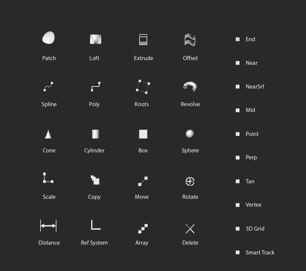
7 Tool palette The tool palette contains all main design tools used in Mindesk. You can select design tool from the palette before start working on your project. Press and keep pressed the left Pad button to open the tool palette. While the palette is open, use right controller to select the desired tool and press the right shoulder button to pick it. Once successfully picked, the tool should appear on the side of each controller. In the tool palette you can activate and deactivate VR SNAP tools as well. The tool palette is divided into two areas: design tools are listed on the left as 3D icons, while VR SNAP functions are listed to the right as text.
8
9 VR Design tools All tools listed are found in the tool palette. In order to use each tool, pick it from the palette and follow the instructions in this table: Select a closed curve and press (S) to make a patched surface from it. Select at least two curves and press (S) to make a lofted surface from them. Select a generating curve or surface, hold (S) and drag the generating surface to extrude it toward a desired extrusion direction. Select a generating surface, hold (S) and drag the generating surface to generate an offset solid. Press (S) to start drawing a 3D spline and add control points. Click (S) on the latest control point to close the spline. Click (S) on the first control point to close the spline. Press (S) to start drawing a 3D polyline and add control points. Click (S) on the latest control point to close the open polyline. Click (S) on the first control point to close the polyline.
 on the first controller to define a pivot point, press and hold (S) on the second controller to define a reference point, drag the second controller to")
10 Select a target object and press (S) to show its control points. Note: you can select control points and move, rotate, and scale them to control the shape of the target object. Select the target object, press and hold (S) on the first controller to define a pivot point, press and hold (S) on the second controller to define a reference point, drag the second controller to revolve the object around the pivot point, release (S) complete the revolution. Note: the rotation axis is defined by the trajectory of the second controller. Press and hold (S), move the controller and release (S) to create a NURBS solid (box, cylinder, cone, sphere). While holding (S) you can change the size, release (S) to complete the action. Select the target object, press and hold (S) on the first controller to define an anchor point, press and hold (S) on the second controller to define a scale reference point, drag the second controller to scale object with respect to the anchor point, release (S) complete the scale. Note: the scale transformation (1D, 2D, or 3D) and the scale factors are determined by the trajectory of the second controller.
11 Select the target object, hold (S) and drag the target object to copy it to a desired destination. Select the target object, hold (S) and drag the target object to move it to its destination. Select the target object, press and hold (S) on the first controller to define a pivot point, press and hold (S) on the second controller to define a rotation reference point, drag the second controller to rotate the object around the pivot point, release (S) complete the rotation. Note: the rotation axis is defined by the trajectory of the second controller. Press (S) to set a measure start point, press (S) again to set a measure end point. Press (S) one more time to reset. Move origin point: hold (S) and drag the reference system to change the location of the Origin point. Rotate axis: press and hold (S) on the first controller to define a pivot point, press and hold (S) on the second controller to define a rotation reference point, drag the second controller to rotate the object around the pivot point, release (S) complete the rotation. Select the target object, press and hold (S), drag the target object to define the direction and the step size of the array, move the controller further in the main direction of the array to increase the number of instances, press (S) again to complete the array. Press (S) to delete a selected object or the nearest object.

12 Precision tools VR SNAPS Located on the right side of the tool palette, VR SNAPS can be activated to make super precise models. Like in Rhino, each snap enables a different geometric constraint: End Near NearSrf Mid Point Perp Tan Vertex 3D Grid Smart Track snaps to the end points of the nearest curve or edge snaps to the closest point on the nearest curve snaps to the closest point on the nearest surface snaps to the middle point on the nearest curve or edge snaps to points and knots snaps to any point on the nearest curve perpendicular to current curve in progress snaps to any point on the nearest curve tangent to current curve in progress snaps on the closest vertex of a mesh snaps to the closest point on a 3D Grid which size is determined by the user enable / disable smart tracking When a snap point is detected, the pointer turns yellow.

13 Magnetic guidelines While drawing a polyline, moving a solid, or copying an object, magnetic guidelines show up to help you aligning geometries along local X, Y, or Z axes. Also, magnetic guidelines helps aligning objects on XY, YZ, or ZX planes and the respective diagonal vectors. Smart Tracking Smart tracking helps to align an object with distant points or edges which the user snapped to. To activate the smart tracking on a snapping point, hover the pointer on it once, hover again to deactivate it Made with by Mindesk team
Alibre Design Tutorial: Loft, Extrude, & Revolve Cut Loft-Tube-1
 Alibre Design Tutorial: Loft, Extrude, & Revolve Cut Loft-Tube-1 Part Tutorial Exercise 5: Loft-Tube-1 [Complete] In this Exercise, We will set System Parameters first, then part options. Then, in sketch
Tutorial Guide to AutoCAD 2014
 Tutorial Guide to AutoCAD 2014 2D Drawing, 3D Modeling Shawna Lockhart SDC P U B L I C AT I O N S For Microsoft Windows Better Textbooks. Lower Prices. www.sdcpublications.com Visit the following websites
Tutorial Guide to AutoCAD 2013
 Tutorial Guide to AutoCAD 2013 2D Drawing, 3D Modeling Shawna Lockhart SDC P U B L I C AT I O N S Schroff Development Corporation For Microsoft Windows Better Textbooks. Lower Prices. www.sdcpublications.com
Tutorial Guide to AutoCAD 2015
 Tutorial Guide to AutoCAD 2015 2D Drawing, 3D Modeling Shawna Lockhart SDC P U B L I C AT I O N S For Microsoft Windows Better Textbooks. Lower Prices. www.sdcpublications.com Powered by TCPDF (www.tcpdf.org)
UNIT 11: Revolved and Extruded Shapes
 UNIT 11: Revolved and Extruded Shapes In addition to basic geometric shapes and importing of three-dimensional STL files, SOLIDCast allows you to create three-dimensional shapes that are formed by revolving
Introduction to ANSYS DesignModeler
 Lecture 4 Planes and Sketches 14. 5 Release Introduction to ANSYS DesignModeler 2012 ANSYS, Inc. November 20, 2012 1 Release 14.5 Preprocessing Workflow Geometry Creation OR Geometry Import Geometry Operations
SolidWorks 95 User s Guide
 SolidWorks 95 User s Guide Disclaimer: The following User Guide was extracted from SolidWorks 95 Help files and was not originally distributed in this format. All content 1995, SolidWorks Corporation Contents
Inventor-Parts-Tutorial By: Dor Ashur
 Inventor-Parts-Tutorial By: Dor Ashur For Assignment: http://www.maelabs.ucsd.edu/mae3/assignments/cad/inventor_parts.pdf Open Autodesk Inventor: Start-> All Programs -> Autodesk -> Autodesk Inventor 2010
Module 2: Radial-Line Sheet-Metal 3D Modeling and 2D Pattern Development: Right Cone (Regular, Frustum, and Truncated)
") Inventor (5) Module 2: 2-1 Module 2: Radial-Line Sheet-Metal 3D Modeling and 2D Pattern Development: Right Cone (Regular, Frustum, and Truncated) In this tutorial, we will learn how to build a 3D model
Inventor (5) Module 2: 2-1 Module 2: Radial-Line Sheet-Metal 3D Modeling and 2D Pattern Development: Right Cone (Regular, Frustum, and Truncated) In this tutorial, we will learn how to build a 3D model
1. Create a 2D sketch 2. Create geometry in a sketch 3. Use constraints to position geometry 4. Use dimensions to set the size of geometry
 2.1: Sketching Many features that you create in Fusion 360 start with a 2D sketch. In order to create intelligent and predictable designs, a good understanding of how to create sketches and how to apply
Modeling Basic Mechanical Components #1 Tie-Wrap Clip
 Modeling Basic Mechanical Components #1 Tie-Wrap Clip This tutorial is about modeling simple and basic mechanical components with 3D Mechanical CAD programs, specifically one called Alibre Xpress, a freely
Drawing with precision
 Drawing with precision Welcome to Corel DESIGNER, a comprehensive vector-based drawing application for creating technical graphics. Precision is essential in creating technical graphics. This tutorial
Introduction to CATIA V5
 Introduction to CATIA V5 Release 17 (A Hands-On Tutorial Approach) Kirstie Plantenberg University of Detroit Mercy SDC PUBLICATIONS Schroff Development Corporation www.schroff.com Better Textbooks. Lower
Hydro Hull. Chapter 21. Boat. A. Save as "HYDRO". Step 1. Open your HULL MID PLANE file (Chapter 2).
.") Chapter 21 Boat Hydro Hull A. Save as "HYDRO". Step 1. Open your HULL MID PLANE file (Chapter 2). Step 2. Click File Menu > Save As. Step 3. Key-in HYDRO for the filename and press ENTER. B. Delete Loft1,
Chapter 21 Boat Hydro Hull A. Save as "HYDRO". Step 1. Open your HULL MID PLANE file (Chapter 2). Step 2. Click File Menu > Save As. Step 3. Key-in HYDRO for the filename and press ENTER. B. Delete Loft1,
Drawing and Assembling
 Youth Explore Trades Skills Description In this activity the six sides of a die will be drawn and then assembled together. The intent is to understand how constraints are used to lock individual parts
Introduction to solid modeling using Onshape
 Onshape is a CAD/solid modeling application. It provides powerful parametric and direct modeling capabilities. It is cloud based therefore you do not need to install any software. Documents are shareable.
Using Google SketchUp
 Using Google SketchUp Opening sketchup 1. From the program menu click on the SketchUp 8 folder and select 3. From the Template Selection select Architectural Design Millimeters. 2. The Welcome to SketchUp
The Revolve Feature and Assembly Modeling
 The Revolve Feature and Assembly Modeling PTC Clock Page 52 PTC Contents Introduction... 54 The Revolve Feature... 55 Creating a revolved feature...57 Creating face details... 58 Using Text... 61 Assembling
Autodesk Inventor Module 17 Angles
 Inventor Self-paced ecourse Autodesk Inventor Module 17 Angles Learning Outcomes When you have completed this module, you will be able to: 1 Describe drawing inclined lines, aligned and angular dimensions,
Introducing SolidWorks
 Introducing SolidWorks SAAST Robotics 2008 SolidWorks Software Visually-based 3-D Mechanical design software Engineers and Designers use it to: Quickly sketch out ideas Experiment with features, dimensions
SolidWorks 2005 Tutorial. and MultiMedia CD. A Step-by-step Project Based Approach Utilizing 3D Solid Modeling
 INSIDE: MultiMedia CD An audio/visual presentation of the tutorial projects SolidWorks 2005 Tutorial and MultiMedia CD A Step-by-step Project Based Approach Utilizing 3D Solid Modeling David C. Planchard
Part Design. Sketcher - Basic 1 13,0600,1488,1586(SP6)
") Part Design Sketcher - Basic 1 13,0600,1488,1586(SP6) In this exercise, we will learn the foundation of the Sketcher and its basic functions. The Sketcher is a tool used to create two-dimensional (2D)
Part Design Sketcher - Basic 1 13,0600,1488,1586(SP6) In this exercise, we will learn the foundation of the Sketcher and its basic functions. The Sketcher is a tool used to create two-dimensional (2D)
SolidWorks Part I - Basic Tools SDC. Includes. Parts, Assemblies and Drawings. Paul Tran CSWE, CSWI
 SolidWorks 2015 Part I - Basic Tools Includes CSWA Preparation Material Parts, Assemblies and Drawings Paul Tran CSWE, CSWI SDC PUBLICATIONS Better Textbooks. Lower Prices. www.sdcpublications.com Powered
SDC. AutoCAD LT 2007 Tutorial. Randy H. Shih. Schroff Development Corporation Oregon Institute of Technology
 AutoCAD LT 2007 Tutorial Randy H. Shih Oregon Institute of Technology SDC PUBLICATIONS Schroff Development Corporation www.schroff.com www.schroff-europe.com AutoCAD LT 2007 Tutorial 1-1 Lesson 1 Geometric
Lesson 6 2D Sketch Panel Tools
 Lesson 6 2D Sketch Panel Tools Inventor s Sketch Tool Bar contains tools for creating the basic geometry to create features and parts. On the surface, the Geometry tools look fairly standard: line, circle,
Lesson 4 Extrusions OBJECTIVES. Extrusions
 Lesson 4 Extrusions Figure 4.1 Clamp OBJECTIVES Create a feature using an Extruded protrusion Understand Setup and Environment settings Define and set a Material type Create and use Datum features Sketch
2809 CAD TRAINING: Part 1 Sketching and Making 3D Parts. Contents
 Contents Getting Started... 2 Lesson 1:... 3 Lesson 2:... 13 Lesson 3:... 19 Lesson 4:... 23 Lesson 5:... 25 Final Project:... 28 Getting Started Get Autodesk Inventor Go to http://students.autodesk.com/
SolidWorks Tutorial 1. Axis
 SolidWorks Tutorial 1 Axis Axis This first exercise provides an introduction to SolidWorks software. First, we will design and draw a simple part: an axis with different diameters. You will learn how to
SolidWize. Online SolidWorks Training. Simple Sweep: Head Scratcher
 SolidWize Online SolidWorks Training Simple Sweep: Head Scratcher Step 1: Creating the Handle: Sketch Using Inches as the unit create a sketch on the Front plane. Start with the sketch shown below: Create
Table of Contents. Lesson 1 Getting Started
 NX Lesson 1 Getting Started Pre-reqs/Technical Skills Basic computer use Expectations Read lesson material Implement steps in software while reading through lesson material Complete quiz on Blackboard
Lesson 4 Holes and Rounds
 Lesson 4 Holes and Rounds 111 Figure 4.1 Breaker OBJECTIVES Sketch arcs in sections Create a straight hole through a part Complete a Sketched hole Understand the Hole Tool Use Info to extract information
Architecture 2012 Fundamentals
 Autodesk Revit Architecture 2012 Fundamentals Supplemental Files SDC PUBLICATIONS Schroff Development Corporation Better Textbooks. Lower Prices. www.sdcpublications.com Tutorial files on enclosed CD Visit
FUSION 360: SKETCHING FOR MAKERS
 FUSION 360: SKETCHING FOR MAKERS LaDeana Dockery 2017 MAKEICT Wichita, KS 1 Table of Contents Interface... 1 File Operations... 1 Opening Existing Models... 1 Mouse Navigation... 1 Preferences... 2 Navigation
NX 7.5. Table of Contents. Lesson 3 More Features
 NX 7.5 Lesson 3 More Features Pre-reqs/Technical Skills Basic computer use Completion of NX 7.5 Lessons 1&2 Expectations Read lesson material Implement steps in software while reading through lesson material
Made Easy. Jason Pancoast Engineering Manager
 3D Sketching Made Easy Jason Pancoast Engineering Manager Today I have taught you to sketch in 3D. It s as easy as counting ONE, TWO, FIVE...er...THREE! When your sketch only lives in Y and in X, Adding
Inventor Activity 5: Lofted Vase
 Inventor Activity 5: Lofted Vase In this tutorial, you will use a few new commands to create a free form Lofted object. Sometimes you want to create an object that is not made up of square, flat, or perfectly
SolidWorks Design & Technology
 SolidWorks Design & Technology Training Course at PHSG Ex 5. Lego man Working with part files 8mm At first glance the Lego man looks complicated but I hope you will see that if you approach a project one
AutoCAD Tutorial First Level. 2D Fundamentals. Randy H. Shih SDC. Better Textbooks. Lower Prices.
 AutoCAD 2018 Tutorial First Level 2D Fundamentals Randy H. Shih SDC PUBLICATIONS Better Textbooks. Lower Prices. www.sdcpublications.com Powered by TCPDF (www.tcpdf.org) Visit the following websites to
1.6.7 Add Arc Length Dimension Modify Dimension Value Check the Sketch Curve Connectivity
 Contents 2D Sketch... 1 1.1 2D Sketch Introduction... 1 1.1.1 2D Sketch... 1 1.1.2 Basic Setting of 2D Sketch... 2 1.1.3 Exit 2D Sketch... 4 1.2 Draw Common Geometry... 5 2.2.1 Points... 5 2.2.2 Lines
AutoCAD LT 2009 Tutorial
 AutoCAD LT 2009 Tutorial Randy H. Shih Oregon Institute of Technology SDC PUBLICATIONS Schroff Development Corporation www.schroff.com Better Textbooks. Lower Prices. AutoCAD LT 2009 Tutorial 1-1 Lesson
AutoCAD LT 2012 Tutorial. Randy H. Shih Oregon Institute of Technology SDC PUBLICATIONS. Schroff Development Corporation
 AutoCAD LT 2012 Tutorial Randy H. Shih Oregon Institute of Technology SDC PUBLICATIONS www.sdcpublications.com Schroff Development Corporation AutoCAD LT 2012 Tutorial 1-1 Lesson 1 Geometric Construction
Principles and Applications of Microfluidic Devices AutoCAD Design Lab - COMSOL import ready
 Principles and Applications of Microfluidic Devices AutoCAD Design Lab - COMSOL import ready Part I. Introduction AutoCAD is a computer drawing package that can allow you to define physical structures
Sketch-Up Guide for Woodworkers
 W Enjoy this selection from Sketch-Up Guide for Woodworkers In just seconds, you can enjoy this ebook of Sketch-Up Guide for Woodworkers. SketchUp Guide for BUY NOW! Google See how our magazine makes you
Module 2.1, 2.2 Review. EF101 Analysis & Skills Module 2.3. Sketched Features and Operations. On-line Help Two Locations
 EF101 Analysis & Skills Module 2.3 Engineering Graphics Revolved Features Placed Features Work Features Module 2.1, 2.2 Review What are the three types of operations for adding features to the base feature?
CNC Router Part 2 Training Tutorial
 CNC Router Part 2 Training Tutorial Prepared by Steve Pilon - Version 1.1 September 2017 A Index B - Intro A- Index B- Intro C- Objective D- Required Items E- Opening CamBam and Loading a DXF F- Preparing
Silhouette Connect Layout... 4 The Preview Window... 5 Undo/Redo... 5 Navigational Zoom Tools... 5 Cut Options... 6
 user s manual Table of Contents Introduction... 3 Sending Designs to Silhouette Connect... 3 Sending a Design to Silhouette Connect from Adobe Illustrator... 3 Sending a Design to Silhouette Connect from
Beginner s Guide to SolidWorks Alejandro Reyes, MSME Certified SolidWorks Professional and Instructor SDC PUBLICATIONS
 Beginner s Guide to SolidWorks 2008 Alejandro Reyes, MSME Certified SolidWorks Professional and Instructor SDC PUBLICATIONS Schroff Development Corporation www.schroff.com www.schroff-europe.com Part Modeling
Using Siemens NX 11 Software. The connecting rod
 Using Siemens NX 11 Software The connecting rod Based on a Catia tutorial written by Loïc Stefanski. At the end of this manual, you should obtain the following part: 1 Introduction. Start NX 11 and open
CREO.1 MODELING A BELT WHEEL
 CREO.1 MODELING A BELT WHEEL Figure 1: A belt wheel modeled in this exercise. Learning Targets In this exercise you will learn: Using symmetry when sketching Using pattern to copy features Using RMB when
Siemens NX11 tutorials. The angled part
 Siemens NX11 tutorials The angled part Adaptation to NX 11 from notes from a seminar Drive-to-trial organized by IBM and GDTech. This tutorial will help you design the mechanical presented in the figure
Creo Revolve Tutorial
 Creo Revolve Tutorial Setup 1. Open Creo Parametric Note: Refer back to the Creo Extrude Tutorial for references and screen shots of the Creo layout 2. Set Working Directory a. From the Model Tree navigate
FLEXLINK DESIGN TOOL VR GUIDE. documentation
 FLEXLINK DESIGN TOOL VR GUIDE User documentation Contents CONTENTS... 1 REQUIREMENTS... 3 SETUP... 4 SUPPORTED FILE TYPES... 5 CONTROLS... 6 EXPERIENCE 3D VIEW... 9 EXPERIENCE VIRTUAL REALITY... 10 Requirements
House Design Tutorial
 House Design Tutorial This House Design Tutorial shows you how to get started on a design project. The tutorials that follow continue with the same plan. When you are finished, you will have created a
Creating a light studio
 Creating a light studio Chapter 5, Let there be Lights, has tried to show how the different light objects you create in Cinema 4D should be based on lighting setups and techniques that are used in real-world
Welcome to Corel DESIGNER, a comprehensive vector-based package for technical graphic users and technical illustrators.
 Workspace tour Welcome to Corel DESIGNER, a comprehensive vector-based package for technical graphic users and technical illustrators. This tutorial will help you become familiar with the terminology and
with MultiMedia CD Randy H. Shih Jack Zecher SDC PUBLICATIONS Schroff Development Corporation
 with MultiMedia CD Randy H. Shih Jack Zecher SDC PUBLICATIONS Schroff Development Corporation WWW.SCHROFF.COM Lesson 1 Geometric Construction Basics AutoCAD LT 2002 Tutorial 1-1 1-2 AutoCAD LT 2002 Tutorial
Training Guide Basics
 Training Guide Basics 2014, Missler Software. 7, Rue du Bois Sauvage F-91055 Evry, FRANCE Web: www.topsolid.com E-mail: info@topsolid.com All rights reserved. TopSolid Design Basics This information is
Virtual Universe Pro. Player Player 2018 for Virtual Universe Pro
 Virtual Universe Pro Player 2018 1 Main concept The 2018 player for Virtual Universe Pro allows you to generate and use interactive views for screens or virtual reality headsets. The 2018 player is "hybrid",
Basic 2D drawing skills in AutoCAD 2017
 Basic 2D drawing skills in AutoCAD 2017 This Tutorial is going to teach you the basic functions of AutoCAD and make you more efficient with the program. Follow all the steps so you can learn all the skills.
J. La Favre Fusion 360 Lesson 4 April 21, 2017
 In this lesson, you will create an I-beam like the one in the image to the left. As you become more experienced in using CAD software, you will learn that there is usually more than one way to make a 3-D
BEST PRACTICES COURSE WEEK 14 PART 2 Advanced Mouse Constraints and the Control Box
 BEST PRACTICES COURSE WEEK 14 PART 2 Advanced Mouse Constraints and the Control Box Copyright 2012 by Eric Bobrow, all rights reserved For more information about the Best Practices Course, visit http://www.acbestpractices.com
Chapter 2. Drawing Sketches for Solid Models. Learning Objectives
 Chapter 2 Drawing Sketches for Solid Models Learning Objectives After completing this chapter, you will be able to: Start a new template file to draw sketches. Set up the sketching environment. Use various
Conquering the Rubicon
 Autodesk Inventor R10 Fundamentals: Conquering the Rubicon Elise Moss SDC PUBLICATIONS Schroff Development Corporation www.schroff.com www.schroff-europe.com Schroff Development Corporation P.O. Box 1334
Welcome to SPDL/ PRL s Solid Edge Tutorial.
 Smart Product Design Product Realization Lab Solid Edge Assembly Tutorial Welcome to SPDL/ PRL s Solid Edge Tutorial. This tutorial is designed to familiarize you with the interface of Solid Edge Assembly
Constructing a Wedge Die
 1-(800) 877-2745 www.ashlar-vellum.com Using Graphite TM Copyright 2008 Ashlar Incorporated. All rights reserved. C6CAWD0809. Ashlar-Vellum Graphite This exercise introduces the third dimension. Discover
AutoCAD 2020 Fundamentals
 Autodesk AutoCAD 2020 Fundamentals ELISE MOSS Autodesk Certified Instructor SDC PUBLICATIONS Better Textbooks. Lower Prices. www.sdcpublications.com Powered by TCPDF (www.tcpdf.org) Visit the following
Wireless Mouse Surfaces
 Wireless Mouse Surfaces Design & Communication Graphics Table of Contents Table of Contents... 1 Introduction 2 Mouse Body. 3 Edge Cut.12 Centre Cut....14 Wheel Opening.. 15 Wheel Location.. 16 Laser..
Module 1C: Adding Dovetail Seams to Curved Edges on A Flat Sheet-Metal Piece
 1 Module 1C: Adding Dovetail Seams to Curved Edges on A Flat Sheet-Metal Piece In this Module, we will explore the method of adding dovetail seams to curved edges such as the circumferential edge of a
1. Creating geometry based on sketches 2. Using sketch lines as reference 3. Using sketches to drive changes in geometry
 4.1: Modeling 3D Modeling is a key process of getting your ideas from a concept to a read- for- manufacture state, making it core foundation of the product development process. In Fusion 360, there are
Getting Started. Chapter. Objectives
 Chapter 1 Getting Started Autodesk Inventor has a context-sensitive user interface that provides you with the tools relevant to the tasks being performed. A comprehensive online help and tutorial system
Starting a New Drawing with a Title Block and Border
 Starting a New Drawing with a Title Block and Border From the File menu select New. Within the New file menu toggle the option Drawing, name the file and turn Off the toggle Use Default Template. Select
SketchUp Training Notes By Professional CAD Systems Ltd Ph
 SketchUp Training Notes By Professional CAD Systems Ltd Ph 07 847 2268 Coffee Table: Using the Rectangle tool, draw a rectangle which is 1100mmx550mm to form the Top of the coffee table. You will need
Introduction to AutoCAD 2012
 Page 1 Introduction to AutoCAD 2012 Alf Yarwood Answers to Multiple choice questions Chapter 1 1. The toolbar at the top of the AutoCAD 2012 window is: (a) The Draw toolbar (b) The Modify toolbar (c) The
Advance Steel. Tutorial
 Advance Steel Tutorial Table of contents About this tutorial... 7 How to use this guide...9 Lesson 1: Creating a building grid...10 Step 1: Creating an axis group in the X direction...10 Step 2: Creating
SDC. SolidWorks Tutorial 2001Plus. A Competency Project Based Approach Utilizing 3D Solid Modeling. David C. Planchard & Marie P.
 2001Plus A Competency Project Based Approach Utilizing 3D Solid Modeling David C. Planchard & Marie P. Planchard SDC PUBLICATIONS www.schroff.com www.schroff-europe.com Project 2 Below are the desired
House Design Tutorial
 House Design Tutorial This House Design Tutorial shows you how to get started on a design project. The tutorials that follow continue with the same plan. When you are finished, you will have created a
CATIA-5 PART-B: 3D CAD, Mechanisms and Finite Element Analysis
 PDHonline Course G351 (10 PDH) CATIA-5 PART-B: 3D CAD, Mechanisms and Finite Element Analysis Instructor: John R. Andrew, P.E. 2012 PDH Online PDH Center 5272 Meadow Estates Drive Fairfax, VA 22030-6658
Introduction to 3D Printing. Activity 1: Design a keychain using computer-aided design software
 Introduction to 3D Printing Activity 1: Design a keychain using computer-aided design software 1 In this activity we ll design a keychain name tag and learn the fundamentals of computer-aided design, the
New Sketch Editing/Adding
 New Sketch Editing/Adding 1. 2. 3. 4. 5. 6. 1. This button will bring the entire sketch to view in the window, which is the Default display. This is used to return to a view of the entire sketch after
Introduction to Circular Pattern Flower Pot
 Prerequisite Knowledge Previous knowledge of the sketching commands Line, Circle, Add Relations, Smart Dimension is required to complete this lesson. Previous examples of Revolved Boss/Base, Cut Extrude,
Alternatively, the solid section can be made with open line sketch and adding thickness by Thicken Sketch.
 Sketcher All feature creation begins with two-dimensional drawing in the sketcher and then adding the third dimension in some way. The sketcher has many menus to help create various types of sketches.
Autodesk AutoCAD 2013 Fundamentals
 Autodesk AutoCAD 2013 Fundamentals Elise Moss SDC P U B L I C AT I O N S Schroff Development Corporation Better Textbooks. Lower Prices. www.sdcpublications.com Visit the following websites to learn more
Creo Parametric 2.0: Introduction to Solid Modeling. Creo Parametric 2.0: Introduction to Solid Modeling
 Creo Parametric 2.0: Introduction to Solid Modeling 1 2 Part 1 Class Files... xiii Chapter 1 Introduction to Creo Parametric... 1-1 1.1 Solid Modeling... 1-4 1.2 Creo Parametric Fundamentals... 1-6 Feature-Based...
BIMXplorer v1.3.1 installation instructions and user guide
 BIMXplorer v1.3.1 installation instructions and user guide BIMXplorer is a plugin to Autodesk Revit (2016 and 2017) as well as a standalone viewer application that can import IFC-files or load previously
House Design Tutorial
 Chapter 2: House Design Tutorial This House Design Tutorial shows you how to get started on a design project. The tutorials that follow continue with the same plan. When you are finished, you will have
12. Creating a Product Mockup in Perspective
 12. Creating a Product Mockup in Perspective Lesson overview In this lesson, you ll learn how to do the following: Understand perspective drawing. Use grid presets. Adjust the perspective grid. Draw and
Module 1E: Parallel-Line Flat Pattern Development of Sheet- Metal Folded Model Wrapping the 3D Space of An Oblique Circular Cylinder
 Inventor (10) Module 1E: 1E- 1 Module 1E: Parallel-Line Flat Pattern Development of Sheet- Metal Folded Model Wrapping the 3D Space of An Oblique Circular Cylinder In this Module, we will explore the topic
Veerapandian.K Mechanical Engg Vedharanyam A manual to mechanical designers How Solid works Works?
 Compiled by Veerapandian.K Mechanical Engg Vedharanyam-614 810 A manual to mechanical designers How Solid works Works? Solid works Overview Solid works main idea is user to create drawing directly in 3D
Table of Contents. Dedication Preface. Chapter 1: Introduction to CATIA V5-6R2015. Chapter 2: Drawing Sketches in the Sketcher Workbench-I.
 Table of Contents Dedication Preface iii xvii Chapter 1: Introduction to CATIA V5-6R2015 Introduction to CATIA V5-6R2015 1-2 CATIA V5 Workbenches 1-2 System Requirements 1-4 Getting Started with CATIA
Exercise01: Circle Grid Obj. 2 Learn duplication and constrain Obj. 4 Learn Basics of Layers
 01: Make new document Details: 8 x 8 02: Set Guides & Grid Preferences Details: Grid style=lines, line=.5, sub=1 03: Draw first diagonal line Details: Start with the longest line 1st. 04: Duplicate first
A TUTORIAL GUIDE TO FOR WINDOWS* Includes Coverage of. Addison-Wesley Publishing Company
 A TUTORIAL GUIDE TO AUTOCAD RELEASE 13 FOR WINDOWS* Includes Coverage of AutoVision and AutoCAD Designer Shawna D. Lockhart TT Addison-Wesley Publishing Company Reading, Massachusetts Menlo Park, California
House Design Tutorial
 Chapter 2: House Design Tutorial This House Design Tutorial shows you how to get started on a design project. The tutorials that follow continue with the same plan. When we are finished, we will have created
AutoCAD 2D. Table of Contents. Lesson 1 Getting Started
 AutoCAD 2D Lesson 1 Getting Started Pre-reqs/Technical Skills Basic computer use Expectations Read lesson material Implement steps in software while reading through lesson material Complete quiz on Blackboard
with Creo Parametric 4.0
 Parametric Modeling with Creo Parametric 4.0 An Introduction to Creo Parametric 4.0 NEW Contains a new chapter on 3D Printing Randy H. Shih SDC PUBLICATIONS Better Textbooks. Lower Prices. www.sdcpublications.com
Chapter 1. Creating, Profiling, Constraining, and Dimensioning the Basic Sketch. Learning Objectives. Commands Covered
 Chapter 1 Creating, Profiling, Constraining, and Dimensioning the Basic Sketch Learning Objectives After completing this chapter, you will be able to: Draw the basic outline (sketch) of designer model.
AutoCAD 2018 Fundamentals
 Autodesk AutoCAD 2018 Fundamentals Elise Moss SDC PUBLICATIONS Better Textbooks. Lower Prices. www.sdcpublications.com Powered by TCPDF (www.tcpdf.org) Visit the following websites to learn more about
Part 8: The Front Cover
 Part 8: The Front Cover 4 Earpiece cuts and housing Lens cut and housing Microphone cut and housing The front cover is similar to the back cover in that it is a shelled protrusion with screw posts extruding
EPS to Rhino Tutorial.
 EPS to Rhino Tutorial. In This tutorial, I will go through my process of modeling one of the houses from our list. It is important to begin by doing some research on the house selected even if you have