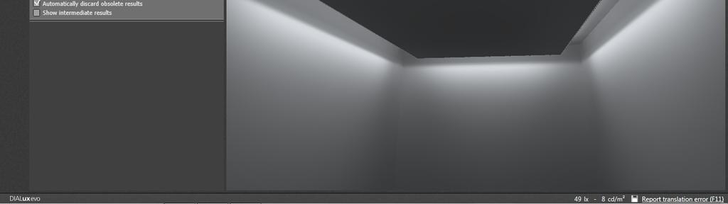
There are two types of cove light in terms of light distribution inside a room
|
|
|
- Ira Little
- 5 years ago
- Views:
Transcription
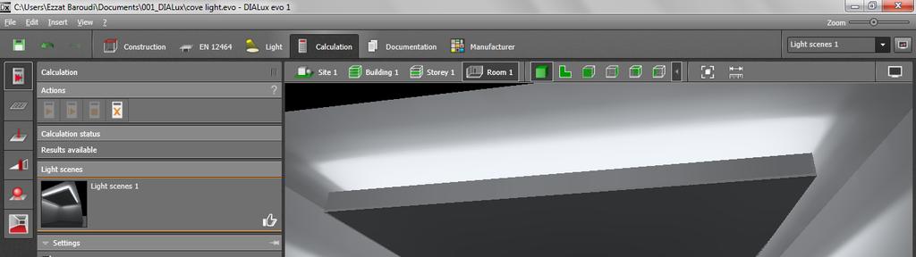
1 DIALux evo Tutorials Tutorial 2 How to create a cove light detail In this tutorial you will learn the following commands. 1. Using help lines 2. Using ceiling. 3. Using cutout 4. Using Boolean operation 5. Some other command There are two types of cove light in terms of light distribution inside a room Outside cove light that distribute lighting to the walls Inside cove light witch distribute lighting to the room Outside cove Inside cove How to create an outside cove 1
. 3. Select line command (3) 4. Draw the line at the boundary of the room form one corner to another (4) 5. Set the offset as 0.")
2 Using help lines For this tutorial let s say that we don t have a cad drawing, but you know the offset form the wall of the cove which is 500 mm all around the room. 1. Make sure you are on construction mode 2. Go to help line tool (2). 3. Select line command (3) 4. Draw the line at the boundary of the room form one corner to another (4) 5. Set the offset as 0.5 m form parallels spaced apart (5). You can make many lines but for this tutorial we need to keep it If the second line is place outside the room rotate the line to be inside the room, alternately make the offset value in minus ( m). 7. Repeat the previous steps to have 4 lines around the room. Tips: You can also you grid help line and set x,y to 0.5 m each. If the cove is round you can select a circle help line. 2

3 Now the boundary of the cove is created by the help line the next step is to create the cove Creating the cove Go to ceiling tool and then click the left button of the mouse in the room to select the room, and then select draw new ceiling command as illustrated below 3

4 Draw the ceiling by click the left mouse on the four corners of the cove boundary and then right click to select CLOSE POLYGON Now a new property window will appear while the ceiling is selected For this tutorial, the value of the false ceiling will be same as default values; however the side offset will be 0.25 where we can use this space for luminaires. 4


5 Tip: use the CTRL+T to open a new tap where you can keep one tab for plan another for side view and may be another for 3d view. Now the cove is created as you could see form the side view We are missing the edge of the cove. Creating the edge To create the edge you can place a cube and scale it to the required diminution Select the depth to be around 15 mm (0.015 m), the height is 150 mm (0.15 m). For the length you can put it directly or use the scale tool 5


6 Now align the four edges to the cove 1. Go to copy and arrange tool. 2. Select the edges and the cove. 3. Align to top. 4. Align to bottom. Tip: If you align to bottom without the step 3 then the cove will get to lower level. Adding cove lighting. Go to LIGHT mode Select the luminaire and then select a line draw the line form one point to another 6


7 DIALux evo Tutorial 02 Put the quantity as required to keep the luminaries in a continuous arrangements. Tips You can click on the arrows to see more options of position and rotations. ARRAIGNMENT: allow you to choose the distance to be between center to center or edge to edge etc. ROTATE: allow you to quickly and easily rotate the luminaires. Go to DISPLAY OPTIONS in the right corner of the software interface and activate Show Light Distributions Curves. Select the luminaire to see if the light is going up to the ceiling or down. 7


8 It the light is going to the floor rotate the light by clicking on the arrow of rotation and rotate 180 degree on x or y After rotation make sure the light destruction is changed to ceiling. Move the luminaires to be inside the cove up. Tip: Select the blue arrow to move the luminaires only in z direction. If you select the green triangle then the luminaires will move in more than one axis. Copy this line to the other area and modify the quantity as required Changing the color temperature 8


9 1. Make sure you are in the LIGHT mode. 2. Go to lamps and select all the luminaires you want to change. 3. Go to correct and click on the word CORRECT. 4. Select the lamp type of the color temperature. 5. Select the value of the color temperature. It is VERY IMPORTANT to click on apply otherwise nothing will be changed Start calculation 9
10 10


11 Creating inside cove Go to ceiling tool and then click the left button of the mouse in the room to select the room, and then select draw new ceiling command as illustrated below Keep the same value as default. 11


12 In the plan view create a grid help line with 1x1 meter; draw the grid form point 1, point 2 and finally point three as illustrated below. You can always rotate the grid after you finish it. Form the property window in the upper right, but now you don t need to rotate if you draw in the order shown above. 12

13 In the 3d view go to cutout tool and select rectangular cutout and draw in the false ceiling in 3d view as illustrated below Go to plan view and edit the cut out move the cutout to be 2x3 using the grid help lines 13


14 Go to 3d view and see the shape it should be similar to the one below Tips If you the cutout selected you cannot see the details change the tool to a different tool to be able to see clearly. Change the color for the apper part to see the details. Now you have a cut out but no edges 14


15 Creating the edges Insert cube and scale it to cover the cut out area, make the height 0.15 m which is the height of the edge. Copy the cube or insert a new cube and make it bigger by 30 mm in x and y 30 mm to allow for 15 mm which is the thickness of the edge. 1. Select both objects and go to copy and arrange tool 2. Click on subtract tab 3. Select the object to remain. 4. Look at the view the object to remain should be in dark red Click on subtract button. 15


16 Insert anther cube with a dimension bigger than the cutout opening by 250 mm form each side, the x,y of the cube will be 3.5, 2.5 m respectively, the height should be 0.3 m Create another cube bigger than the last cube by some value, it dosent matter the value but should be bigger thencut the last two cubes to keep the bigger one as a boundary, make sure the red is the outer one Now you have the edge and the back boundery of the luminaires as in the next image 16


17 You can combine both objects by copy and arrange tool and then combine tab combine Move the combined object to the ceiling You can align the object to false ceiling by using align command in the copy and arrange tool. 17


18 Add the luminaires as explained in the outside cove and start calculation. 18
How to create a cove for cove lighting in DIALux In this tutorial you will learn how to make a cove similar to the one in the following image
 How to create a cove for cove lighting in DIALux In this tutorial you will learn how to make a cove similar to the one in the following image The cove dimension will be 4 meter by 5 meter and the other
DIALux evo Tutorial 10- Using powerful tool copy and arrange
 DIALux evo Tutorial 10 Using powerful tool-copy and arrange This tutorial was made by DIALux evo 4 to explain the powerful tool of copy and arrange tool Also you could see DIALux evo Tutorial 5 If you
Cube in a cube Fusion 360 tutorial
 Cube in a cube Fusion 360 tutorial n Before using these instructions, it is helpful to watch this video screencast of the CAD drawing actually being done in the software. Click to link to the video tutorial.
Using Siemens NX 11 Software. The connecting rod
 Using Siemens NX 11 Software The connecting rod Based on a Catia tutorial written by Loïc Stefanski. At the end of this manual, you should obtain the following part: 1 Introduction. Start NX 11 and open
Diane Burton, STEM Outreach.
 123D Design Tutorial: LED decoration Before using these instructions, it is very helpful to watch this video screencast of the CAD drawing actually being done in the software. Click this link for the video
Advanced CO2 car Import CAM Procedures
 Advanced CO2 car Import CAM Procedures While the standard CO2 car tutorial within Quick CAM has a part that is sized to fit the billet as custom designed cars are produced this will not be the case. Before
Module 1C: Adding Dovetail Seams to Curved Edges on A Flat Sheet-Metal Piece
 1 Module 1C: Adding Dovetail Seams to Curved Edges on A Flat Sheet-Metal Piece In this Module, we will explore the method of adding dovetail seams to curved edges such as the circumferential edge of a
Using Siemens NX 11 Software. Sheet Metal Design - Casing
 Using Siemens NX 11 Software Sheet Metal Design - Casing Based on a YouTube NX tutorial 1. 1 https://www.youtube.com/watch?v=-siyi1vz87k A&M CAD in mechanical engineering 1 1 Introduction. Start NX 11
Part 6: Checking an existing kitchen design
 Welcome, Thank you for choosing, an innovative surveying tool for kitchen surveying. To help you get started with, we will guide you on the following pages through the registration, installation and handling
Create A Mug. Skills Learned. Settings Sketching 3-D Features. Revolve Offset Plane Sweep Fillet Decal* Offset Arc
 Create A Mug Skills Learned Settings Sketching 3-D Features Slice Line Tool Offset Arc Revolve Offset Plane Sweep Fillet Decal* Tutorial: Creating A Custom Mug There are somethings in this world that have
dialux dialux 2.0 CAD dialux 2.0
 dialux 20 dialux 20 CAD - - - - dialux 20 CAD CAD ((zoom)) 3D (ground plan) 3D (( roam))(( move))(( (side) zoom)) (( rotate)) ((move)) ((PAN)) (wheel mouse) (wheel) dialux 20 CAD context 3D CAD context
Alibre Design Tutorial: Loft, Extrude, & Revolve Cut Loft-Tube-1
 Alibre Design Tutorial: Loft, Extrude, & Revolve Cut Loft-Tube-1 Part Tutorial Exercise 5: Loft-Tube-1 [Complete] In this Exercise, We will set System Parameters first, then part options. Then, in sketch
Revit Structure 2013 Basics
 Revit Structure 2013 Basics Framing and Documentation Elise Moss Supplemental Files SDC P U B L I C AT I O N S Schroff Development Corporation Better Textbooks. Lower Prices. www.sdcpublications.com Tutorial
Making a Custom Symbol. Making a Custom Symbol in Chief Architect
 TIP in Chief Architect INTRODUCTION Being able to make your own symbols in Chief Architect can be very useful. Not many users take the time to learn how to do this because they believe it to be a difficult
Tutorial Building the Nave Arcade
 Tutorial: Digital Gothic AH C117B (Winter 2017) Tutorial Building the Nave Arcade Overview: Step 1: Determining and Drawing The Arch (Quinto Arch) Step 2: Extrude Molding Profile Step 3: Adding Walls Step
Module 2: Radial-Line Sheet-Metal 3D Modeling and 2D Pattern Development: Right Cone (Regular, Frustum, and Truncated)
") Inventor (5) Module 2: 2-1 Module 2: Radial-Line Sheet-Metal 3D Modeling and 2D Pattern Development: Right Cone (Regular, Frustum, and Truncated) In this tutorial, we will learn how to build a 3D model
Inventor (5) Module 2: 2-1 Module 2: Radial-Line Sheet-Metal 3D Modeling and 2D Pattern Development: Right Cone (Regular, Frustum, and Truncated) In this tutorial, we will learn how to build a 3D model
PowerEn.ir CAD. 3D,(ground plan) (wheel mouse) (wheel) dialux 2.0
 (wheel mouse) (wheel) dialux 2.0") PowerEnir CAD CAD ((zoom)) 3D (ground plan) 3D (( roam))(( move))(( (side) zoom)) (( rotate)) ((move)) ((PAN)) (wheel mouse) (wheel) dialux 20 PowerEnir CAD context 3D CAD context ((Dxf )) (insert) context
PowerEnir CAD CAD ((zoom)) 3D (ground plan) 3D (( roam))(( move))(( (side) zoom)) (( rotate)) ((move)) ((PAN)) (wheel mouse) (wheel) dialux 20 PowerEnir CAD context 3D CAD context ((Dxf )) (insert) context
Revit Structure 2012 Basics:
 SUPPLEMENTAL FILES ON CD Revit Structure 2012 Basics: Framing and Documentation Elise Moss autodesk authorized publisher SDC PUBLICATIONS www.sdcpublications.com Schroff Development Corporation Structural
Advance Steel. Tutorial
 Advance Steel Tutorial Table of contents About this tutorial... 7 How to use this guide...9 Lesson 1: Creating a building grid...10 Step 1: Creating an axis group in the X direction...10 Step 2: Creating
Modeling Basic Mechanical Components #1 Tie-Wrap Clip
 Modeling Basic Mechanical Components #1 Tie-Wrap Clip This tutorial is about modeling simple and basic mechanical components with 3D Mechanical CAD programs, specifically one called Alibre Xpress, a freely
Create a Flowchart in Word
 Create a Flowchart in Word A flowchart is a diagram of steps, movements or actions involved in a system or activity. Flowcharts use conventional geometric symbols and arrows to define relationships and
SolidWorks Design & Technology
 SolidWorks Design & Technology Training Course at PHSG Ex 5. Lego man Working with part files 8mm At first glance the Lego man looks complicated but I hope you will see that if you approach a project one
Basic 2D drawing skills in AutoCAD 2017
 Basic 2D drawing skills in AutoCAD 2017 This Tutorial is going to teach you the basic functions of AutoCAD and make you more efficient with the program. Follow all the steps so you can learn all the skills.
Assignment 5 CAD Mechanical Part 1
 Assignment 5 CAD Mechanical Part 1 Objectives In this assignment you will apply polyline, offset, copy, move, and rotated dimension commands, as well as skills learned in earlier assignments. Getting Started
Revit Structure 2014 Basics
 Revit Structure 2014 Basics Framing and Documentation Elise Moss Authorized Author SDC P U B L I C AT I O N S Better Textbooks. Lower Prices. www.sdcpublications.com Powered by TCPDF (www.tcpdf.org) Visit
CAD Orientation (Mechanical and Architectural CAD)
") Design and Drafting Description This is an introductory computer aided design (CAD) activity designed to give students the foundational skills required to complete future lessons. Students will learn all
Design and Drafting Description This is an introductory computer aided design (CAD) activity designed to give students the foundational skills required to complete future lessons. Students will learn all
Kitchen and Bath Design Tutorial
 Kitchen and Bath Design Tutorial This tutorial continues where the Interior Design Tutorial left off. You should save this tutorial using a new name to archive your previous work. The tools and techniques
Unit 3.11 Introduction to Absolute & Polar Coordinates in AutoCAD Ardrey Kell High School Charlotte, NC Date: 11/18/13 (Revision II)
") Unit 3.11 Introduction to Absolute & Polar Coordinates in AutoCAD X,Y,Z @3
Unit 3.11 Introduction to Absolute & Polar Coordinates in AutoCAD X,Y,Z @3
Creo Revolve Tutorial
 Creo Revolve Tutorial Setup 1. Open Creo Parametric Note: Refer back to the Creo Extrude Tutorial for references and screen shots of the Creo layout 2. Set Working Directory a. From the Model Tree navigate
ACAD-BAU TUTORIAL For BricsCAD platform
 ACAD-BAU TUTORIAL WWW.ARHINOVA.SI For BricsCAD platform August 06 WORKSPACE ACAD-BAU RIBBON ACAD-BAU CONTROL BAR F ACAD-BAU PALETTES BASIC SETTINGS Use New command and open the template called ACB_International.DWT.
Chapter 6 Title Blocks
 Chapter 6 Title Blocks In previous exercises, every drawing started by creating a number of layers. This is time consuming and unnecessary. In this exercise, we will start a drawing by defining layers
Part 8: The Front Cover
 Part 8: The Front Cover 4 Earpiece cuts and housing Lens cut and housing Microphone cut and housing The front cover is similar to the back cover in that it is a shelled protrusion with screw posts extruding
New Sketch Editing/Adding
 New Sketch Editing/Adding 1. 2. 3. 4. 5. 6. 1. This button will bring the entire sketch to view in the window, which is the Default display. This is used to return to a view of the entire sketch after
ARCHLine.XP Interior Windows. Learning Interior. Learning material for the basics of ARCHLine.XP Interior. ARCHLine.
 ARCHLine.XP Interior 2010 Windows Learning Interior Learning material for the basics of ARCHLine.XP Interior ARCHLine.XP Interior Information in this document is subject to change without notice and does
Welcome to SPDL/ PRL s Solid Edge Tutorial.
 Smart Product Design Product Realization Lab Solid Edge Assembly Tutorial Welcome to SPDL/ PRL s Solid Edge Tutorial. This tutorial is designed to familiarize you with the interface of Solid Edge Assembly
Advanced Modeling Techniques Sweep and Helical Sweep
 Advanced Modeling Techniques Sweep and Helical Sweep Sweep A sweep is a profile that follows a path placed on a datum. It is important when creating a sweep that the designer plans the size of the path
Advance Concrete. Tutorial
 Advance Concrete Tutorial Table of contents About this tutorial... 9 How to use this guide... 10 Lesson 1: Creating a building grid... 11 Step 1: Create a default building grid... 11 Step 2: Set the distances
with MultiMedia CD Randy H. Shih Jack Zecher SDC PUBLICATIONS Schroff Development Corporation
 with MultiMedia CD Randy H. Shih Jack Zecher SDC PUBLICATIONS Schroff Development Corporation WWW.SCHROFF.COM Lesson 1 Geometric Construction Basics AutoCAD LT 2002 Tutorial 1-1 1-2 AutoCAD LT 2002 Tutorial
Part Design. Sketcher - Basic 1 13,0600,1488,1586(SP6)
") Part Design Sketcher - Basic 1 13,0600,1488,1586(SP6) In this exercise, we will learn the foundation of the Sketcher and its basic functions. The Sketcher is a tool used to create two-dimensional (2D)
Part Design Sketcher - Basic 1 13,0600,1488,1586(SP6) In this exercise, we will learn the foundation of the Sketcher and its basic functions. The Sketcher is a tool used to create two-dimensional (2D)
Nut and Bolt Tutorial
 Thread Representations Nut and Bolt Tutorial Parts to a Thread Thread Dimensioning Major Diameter Thread Series (IE UNC, UNF, ACME, etc) ½ - 13 UNC 2 A or B A = External B = Internal Threads per Inch Class
Drawing and Assembling
 Youth Explore Trades Skills Description In this activity the six sides of a die will be drawn and then assembled together. The intent is to understand how constraints are used to lock individual parts
Activity 1 Modeling a Plastic Part
 Activity 1 Modeling a Plastic Part In this activity, you will model a plastic part. When completed, your plastic part should look like the following two illustrations. While building this model, take time
Tutorial 2: Setting up the Drawing Environment
 Drawing size With AutoCAD all drawings are done to FULL SCALE. The drawing limits will depend on the size of the items being drawn. For example if our drawing is the plan of a floor 23.8m X 15m then we
Kitchen and Bath Design Tutorial
 Kitchen and Bath Design Tutorial This tutorial continues where the Interior Design Tutorial left off. You should save this tutorial using a new name to archive your previous work. The tools and techniques
EPS to Rhino Tutorial.
 EPS to Rhino Tutorial. In This tutorial, I will go through my process of modeling one of the houses from our list. It is important to begin by doing some research on the house selected even if you have
AutoCAD LT 2012 Tutorial. Randy H. Shih Oregon Institute of Technology SDC PUBLICATIONS. Schroff Development Corporation
 AutoCAD LT 2012 Tutorial Randy H. Shih Oregon Institute of Technology SDC PUBLICATIONS www.sdcpublications.com Schroff Development Corporation AutoCAD LT 2012 Tutorial 1-1 Lesson 1 Geometric Construction
PlanSwift 3D Viewer Plugin User Guide
 PlanSwift 3D Viewer Plugin User Guide UPDATED ON 7/13/2018 PlanSwift Authored by: Dave Hansen 1 Table of Contents Overview... 3 Purchasing and Installation... 4 Purchasing Plugins... 4 Installation and
AutoCAD 2D. Table of Contents. Lesson 1 Getting Started
 AutoCAD 2D Lesson 1 Getting Started Pre-reqs/Technical Skills Basic computer use Expectations Read lesson material Implement steps in software while reading through lesson material Complete quiz on Blackboard
Getting Started. Before You Begin, make sure you customized the following settings:
 Getting Started Getting Started Before getting into the detailed instructions for using Generative Drafting, the following tutorial aims at giving you a feel of what you can do with the product. It provides
Create a Simple Architectural Structure (Architectural CAD)
") Description In this activity the teacher will demonstrate how to transform the 2D floor plan into a 3D structure, using the plan created in the Drawing of a Simple Building activity. Lesson Objectives
Description In this activity the teacher will demonstrate how to transform the 2D floor plan into a 3D structure, using the plan created in the Drawing of a Simple Building activity. Lesson Objectives
Kitchen and Bath Design Tutorial
 Kitchen and Bath Design Tutorial This tutorial continues where the Interior Design Tutorial left off. You should save this tutorial using a new name to archive your previous work. The tools and techniques
Evaluation Chapter by CADArtifex
 The premium provider of learning products and solutions www.cadartifex.com EVALUATION CHAPTER 2 Drawing Sketches with SOLIDWORKS In this chapter: Invoking the Part Modeling Environment Invoking the Sketching
Lesson 6 2D Sketch Panel Tools
 Lesson 6 2D Sketch Panel Tools Inventor s Sketch Tool Bar contains tools for creating the basic geometry to create features and parts. On the surface, the Geometry tools look fairly standard: line, circle,
SolidWorks Part I - Basic Tools SDC. Includes. Parts, Assemblies and Drawings. Paul Tran CSWE, CSWI
 SolidWorks 2015 Part I - Basic Tools Includes CSWA Preparation Material Parts, Assemblies and Drawings Paul Tran CSWE, CSWI SDC PUBLICATIONS Better Textbooks. Lower Prices. www.sdcpublications.com Powered
Siemens NX11 tutorials. The angled part
 Siemens NX11 tutorials The angled part Adaptation to NX 11 from notes from a seminar Drive-to-trial organized by IBM and GDTech. This tutorial will help you design the mechanical presented in the figure
1. Create a 2D sketch 2. Create geometry in a sketch 3. Use constraints to position geometry 4. Use dimensions to set the size of geometry
 2.1: Sketching Many features that you create in Fusion 360 start with a 2D sketch. In order to create intelligent and predictable designs, a good understanding of how to create sketches and how to apply
User s Manual ❿ Drawings-Detailing
 User s Manual ❿ Drawings-Detailing 2 CONTENTS I. THE NEW UPGRADED INTERFACE of SCADA Pro 4 1. UNITS 5 1.1 Drawings-Detailing 5 I. Files 6 II. Drawing 25 III. Formworks 30 IV. Edit 45 V. View 58 VI. Layers
Converting a solid to a sheet metal part tutorial
 Converting a solid to a sheet metal part tutorial Introduction Sometimes it is easier to start with a solid and convert it to create a sheet metal part. This tutorial will guide you through the process
Sash Clamp. Sash Clamp SW 2015 Design & Communication Graphics Page 1.
 Sash Clamp 1 Introduction: The Sash clamp consists of nine parts. In creating the clamp we will be looking at the improvements made by SolidWorks in linear patterns, adding threads and in assembling the
Introduction to Autodesk Inventor for F1 in Schools (Australian Version)
") Introduction to Autodesk Inventor for F1 in Schools (Australian Version) F1 in Schools race car In this course you will be introduced to Autodesk Inventor, which is the centerpiece of Autodesk s Digital
Introduction to Autodesk Inventor for F1 in Schools (Australian Version) F1 in Schools race car In this course you will be introduced to Autodesk Inventor, which is the centerpiece of Autodesk s Digital
Drawing with precision
 Drawing with precision Welcome to Corel DESIGNER, a comprehensive vector-based drawing application for creating technical graphics. Precision is essential in creating technical graphics. This tutorial
Architecture 2012 Fundamentals
 Autodesk Revit Architecture 2012 Fundamentals Supplemental Files SDC PUBLICATIONS Schroff Development Corporation Better Textbooks. Lower Prices. www.sdcpublications.com Tutorial files on enclosed CD Visit
LightPro User Guide <Virtual Environment> 6.0
 LightPro User Guide 6.0 Page 1 of 23 Contents 1. Introduction to LightPro...3 2. Lighting Database...3 3. Menus...4 3.1. File Menu...4 3.2. Edit Menu...5 3.2.1. Selection Set sub-menu...6
PASS Sample Size Software. These options specify the characteristics of the lines, labels, and tick marks along the X and Y axes.
 Chapter 940 Introduction This section describes the options that are available for the appearance of a scatter plot. A set of all these options can be stored as a template file which can be retrieved later.
COURSE: INTRODUCTION TO CAD GRADES: UNIT: Measurement
 UNIT: Measurement - Students will demonstrate correctness in measuring using various scales and instruments. Demonstrate the various marks that make up a ruler including 1/16, 1/8, ¼ and ½. Assessment
Applied Precast Concrete Detailing
 Applied Precast Concrete Detailing Tekla Structures 11.0 August 30, 2005 Copyright 2005 Tekla Corporation Copyright 2005 Tekla Corporation Applied Precast Concrete Detailing i Copyright 2005 Tekla Corporation
Tutorial 1: Install Forecaster HD (Win XP, Vista, 7, 8)
") Tutorial 1: Install Forecaster HD (Win XP, Vista, 7, 8) Download Forecaster HD (FHD) from Community s website http://www.communitypro.com/productlist/135-forecaster-ceiling-system-software Open Setup.exe
Tutorial 1: Install Forecaster HD (Win XP, Vista, 7, 8) Download Forecaster HD (FHD) from Community s website http://www.communitypro.com/productlist/135-forecaster-ceiling-system-software Open Setup.exe
Dean Muccio AutoCAD Interior Designer. for the. AutoCAD for Mac and PC SDC. Better Textbooks. Lower Prices.
 Dean Muccio AutoCAD 2020 for the Interior Designer AutoCAD for Mac and PC SDC P U B L I C AT I O N S Better Textbooks. Lower Prices. www.sdcpublications.com Powered by TCPDF (www.tcpdf.org) Visit the following
Engineering & Computer Graphics Workbook Using SolidWorks 2014
 Engineering & Computer Graphics Workbook Using SolidWorks 2014 Ronald E. Barr Thomas J. Krueger Davor Juricic SDC PUBLICATIONS Better Textbooks. Lower Prices. www.sdcpublications.com Powered by TCPDF (www.tcpdf.org)
Getting Started. with Easy Blue Print
 Getting Started with Easy Blue Print User Interface Overview Easy Blue Print is a simple drawing program that will allow you to create professional-looking 2D floor plan drawings. This guide covers the
AutoCAD LT 2009 Tutorial
 AutoCAD LT 2009 Tutorial Randy H. Shih Oregon Institute of Technology SDC PUBLICATIONS Schroff Development Corporation www.schroff.com Better Textbooks. Lower Prices. AutoCAD LT 2009 Tutorial 1-1 Lesson
To start a new drawing Select File New then from the dialog box, which appears select Normal.dft followed by OK.
 Draft Tutorial This tutorial provides step-by-step instructions for the detailing of a drawing of the anchor block shown opposite. As you create this drawing, you will use the following drafting techniques:
Dean Muccio. AutoCAD 2018 for the. Interior Designer. AutoCAD for Mac and PC SDC. Better Textbooks. Lower Prices.
 Dean Muccio AutoCAD 2018 for the Interior Designer AutoCAD for Mac and PC SDC P U B L I C AT I O N S Better Textbooks. Lower Prices. www.sdcpublications.com Powered by TCPDF (www.tcpdf.org) Visit the following
Principles and Practice
 Principles and Practice An Integrated Approach to Engineering Graphics and AutoCAD 2011 Randy H. Shih Oregon Institute of Technology SDC PUBLICATIONS www.sdcpublications.com Schroff Development Corporation
Apex v5 Assessor Introductory Tutorial
 Apex v5 Assessor Introductory Tutorial Apex v5 Assessor Apex v5 Assessor includes some minor User Interface updates from the v4 program but attempts have been made to simplify the UI for streamlined work
84 part video tutorial training course. The course is 100% free with no catches or exclusions. You don
 Please Note: If you're new to Revit, you may be interested in my " Beginner's Guide to Revit Architecture " 84 part video tutorial training course. The course is 100% free with no catches or exclusions.
lindab comfort Step by step manual DIMcomfort 4.0
 Step by step manual DIMcomfort 4.0 1 Contents Start-up DIMcomfort 4.0 3 Room Setup 4 Room information 4 Dimensions 5 Comfort zone 6 Dimension criteria 7 Selection of air terminal devices 8 Product search
Vectorworks / MiniCAD Tutorials
 Vectorworks / MiniCAD Tutorials Tutorial 1: Construct a simple model of a little house Tutorial 2: Construct a 4 view Orthographic drawing of the Model These tutorials are available as Adobe Acrobat 4
1. Start with scatter plot: 2. Find corner points. 3. Capture image. 4. Corners
 1. Start with scatter plot: 2. Find corner points Easiest way to insert picture properly in GeoGebra is to have corner points. We see that: bottom corner is (2,10) top corner is (9,21) 3. Capture image
Engineering & Computer Graphics Workbook Using SOLIDWORKS
 Engineering & Computer Graphics Workbook Using SOLIDWORKS 2017 Ronald E. Barr Thomas J. Krueger Davor Juricic SDC PUBLICATIONS Better Textbooks. Lower Prices. www.sdcpublications.com Powered by TCPDF (www.tcpdf.org)
Kitchen and Bath Design Tutorial
 Adding Cabinets Chapter 5: Kitchen and Bath Design Tutorial This tutorial continues where the Materials Tutorial left off. You should save this tutorial using a new name to archive your previous work.
BUILD 3 Tri-Color Candy Corn
 BUILD 3 Tri-Color Candy Corn 1. Go to www.tinkercad.com and SIGN UP for a free account then Sign In 2. Select the Create new design button to open the editing screen 3. Select Properties from the Design
TUTORIAL 4: Combined Axial and Bending Problem Sketch Path Sweep Initial Project Space Setup Static Structural ANSYS
 TUTORIAL 4: Combined Axial and Bending Problem In this tutorial you will learn how to draw a bar that has bends along its length and therefore will have both axial and bending stresses acting on cross-sections
Solidworks tutorial. 3d sketch project. A u t h o r : M. G h a s e m i. C o n t a c t u s : i n f s o l i d w o r k s a d v i s o r.
 Solidworks tutorial 3d sketch project A u t h o r : M. G h a s e m i C o n t a c t u s : i n f o @ s o l i d w o r k s a d v i s o r. c o m we will create this frame during the tutorial : In this tutorial
VisualCAM 2018 TURN Quick Start MecSoft Corporation
 2 Table of Contents About this Guide 4 1 About... the TURN Module 4 2 Using this... Guide 4 3 Useful... Tips 5 Getting Ready 7 1 Running... VisualCAM 2018 7 2 About... the VisualCAD Display 7 3 Launch...
The Revolve Feature and Assembly Modeling
 The Revolve Feature and Assembly Modeling PTC Clock Page 52 PTC Contents Introduction... 54 The Revolve Feature... 55 Creating a revolved feature...57 Creating face details... 58 Using Text... 61 Assembling
SDC. AutoCAD LT 2007 Tutorial. Randy H. Shih. Schroff Development Corporation Oregon Institute of Technology
 AutoCAD LT 2007 Tutorial Randy H. Shih Oregon Institute of Technology SDC PUBLICATIONS Schroff Development Corporation www.schroff.com www.schroff-europe.com AutoCAD LT 2007 Tutorial 1-1 Lesson 1 Geometric
Chapter 5 Sectional Views
 Chapter 5 Sectional Views There are a number of different types of sectional views that can be drawn. A few of the more common ones are: full sections, half sections, broken sections, rotated or revolved
Lab 3 Introduction to SolidWorks I Silas Bernardoni 10/9/2008
 1 Introduction This lab is designed to provide you with basic skills when using the 3D modeling program SolidWorks. You will learn how to build parts, assemblies and drawings. You will be given a physical
Creating a light studio
 Creating a light studio Chapter 5, Let there be Lights, has tried to show how the different light objects you create in Cinema 4D should be based on lighting setups and techniques that are used in real-world
For more information on STAIRDESIGNER please visit www. Stairdesignsoftware.net
 Getting Started with Stair Designer Software Introduction If you are reading this you are interested in stair building, either as a professional stair builder, carpenter or architect or as an amateur woodworker
CC3 and Perspectives A Campaign Cartographer 3/3+ Tutorial. Part 1 - Basics
 CC3 and Perspectives A Campaign Cartographer 3/3+ Tutorial by Joachim de Ravenbel Part 1 - Basics Conventions Throughout this tutorial, I will use a color coding to clearly identify all the keywords: Sheet
Autodesk Inventor 2016 Creating Sketches
 Autodesk Inventor 2016 Creating Sketches 2D Sketch Practice 1 1. Launch Autodesk Inventor 2016 2. Create a new Part file (.ipt) 3. Save File As a. Click on the save icon. b. Save you file onto your flash
Placing Notes on the Rectangular Problem
 C h a p t e r 4 Placing Notes on the Rectangular Problem In this chapter, you will learn the following to World Class standards: 1. Use the tools and toolbar for simple 2D Computer Aided Drafting (CAD)
Photoshop CC 2018 Essential Skills
 Photoshop CC 2018 Essential Skills Adobe Photoshop Creative Cloud 2018 University Information Technology Services Learning Technology, Training, Audiovisual and Outreach Copyright 2018 KSU Division of
Visio 2010 Tutorial. Design of PLS Systems
 Visio 2010 Tutorial ISE 453 Design of PLS Systems This tutorial is designed to teach you to use Visio to draw a facility layout. It was adapted for Visio by Derek Shields and for older Visio versions by
SolidWorks 95 User s Guide
 SolidWorks 95 User s Guide Disclaimer: The following User Guide was extracted from SolidWorks 95 Help files and was not originally distributed in this format. All content 1995, SolidWorks Corporation Contents
Assignment 6 CAD Mechanical Part 1 Editing Tools Objectives
 Assignment 6 CAD Mechanical Part 1 Editing Tools Objectives In this assignment you will apply the explode and rectangular array commands, as well as skills learned in earlier assignments. Getting Started