IMPORTANT WARRANTY & INSTALLATION INSTRUCTIONS ATTACHED
|
|
|
- Anabel Sutton
- 6 years ago
- Views:
Transcription
1 IMPORTANT WARRANTY & INSTALLATION INSTRUCTIONS ATTACHED For Full-Color Installation Instructions, Please Visit: VOLANT.COM and Search by Part Number Please be sure to review the enclosed instructions prior to beginning the installation process. If you have any questions about the enclosed parts, instructions or encounter a problem during installation: CALL VOLANT PERFORMANCE TECHNICAL ASSISTANCE AT VOLANT PERFORMANCE l 140 BLAZE INDUSTRIAL PKWY, BEREA, OHIO 44017
2 Please take time to read and understand these installation instructions. Volant recommends that the installation of this system be performed by a qualified service center or professional installer who has the necessary equipment, tools and experienced personnel. However, if you decide to perform this install the use of an additional person may be required. CAUTION: Never work on a hot engine bay. Allow time for the vehicle to cool. Recommended Tools: Flathead Screwdriver Assorted Socket Set Ratchet Ratchet Extension Please confirm that all parts are present before beginning the installation. Bill of Materials 1 Plastic air box 1 #56 Clamp 1 #64 Clamp 3 1/2 Vacuum Hose 1 Plastic air duct x 4in Reducer 1 MAF Gasket 1 Fender gasket 1 Air box lid 1 Lid gasket 1 Air duct gasket 1 6mm x 25 Bolt 1 1/4 x 7/8 Washer 6 #10 Washer 1 1/4 Lock washer 1 1/2 Straight fitting 2 6mm Set screws 2 4mm x 12 Sensor screws 6 10/32 Truss screws 2 6mm Couplers 5 Truss heads screws 5 Rubber washers NPT fitting 1 PowerCore filter 2
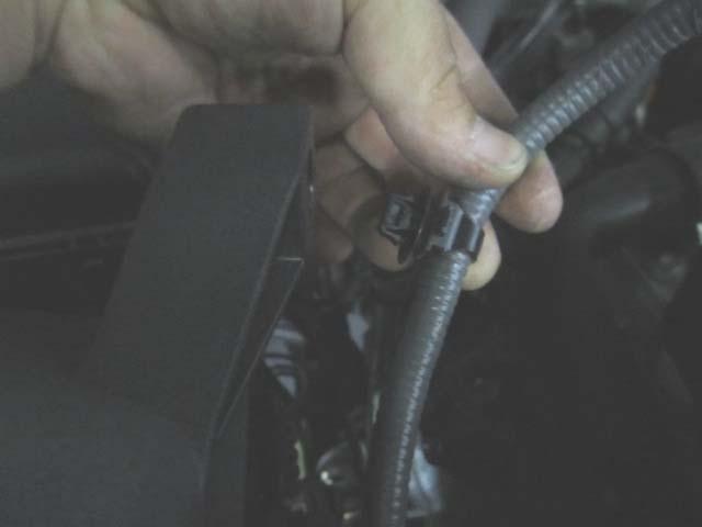
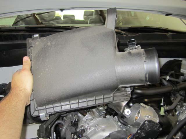
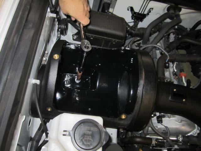
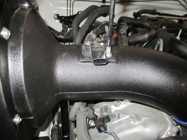
3 Installation Instructions: 1. Before you begin the install you must disconnect the negative battery cable. Failure to disconnect the battery may cause a check engine light or damage to your engine. 2. Remove the engine cover by pulling up and out. (Fig A) 3. Disconnect the MAF sensor harness from the MAF sensor. (Fig B) 4. Remove the 1/2 breather hose from the factory air duct. (Fig C) 5. Remove the 1/8 breather hose from the factory air duct. (Fig D) 6. Remove the MAF harness from the factory air box. (Fig E) 7. Loosen the clamp holding the duct to the air box. (Fig F) 8. Loosen the clamp holding the duct to the throttle body. (Fig G) 9. Remove the factory air duct. (Fig H) 10. Loosen the bolt in front of the factory air box. (Fig I) 11. Loosen the bolt behind of the factory air box. (Fig J) 12. Remove the factory air box. (Fig K) 13. Remove the paper backing from the fender gasket and press it onto the Volant box. (Fig L) 14. Remove the paper backing from the air duct gasket and press it onto the Volant box. (Fig M) 15. Attach the Volant duct to the Volant box using the 6 #10 washers and truss head screws. (Fig N) 16. Slide the reducer and clamps onto the Volant duct. (Fig O) 17. Place the Volant CAI into the factory position. (Fig P) 18. Tighten the box into place using the provided 6mm x 25 bolt lock washer and washer. (Fig Q) 19. Press the 3in breather hose onto the Volant duct. (Fig R) 20. Press the coupler into the 1/2 breather hose. (Fig S) 21. Press the factory breather hose onto the 1/2 coupler. (Fig T) 3
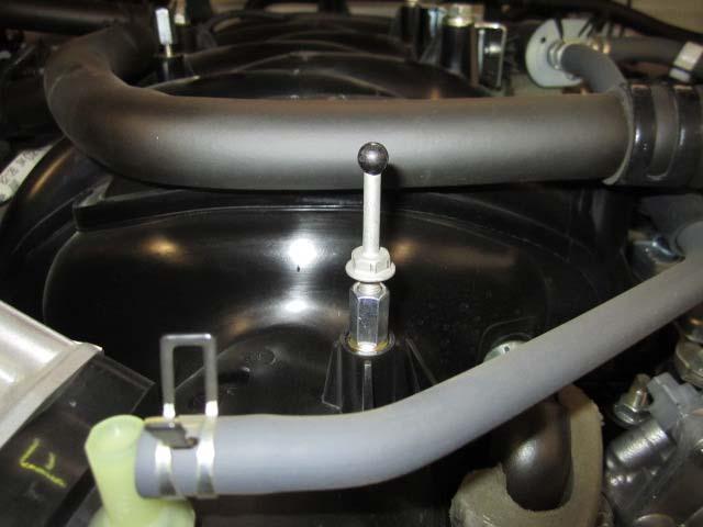
4 22. Press the factory 1/8 breather hose onto the 1/8 npt fitting on the Volant duct. (Fig U) 23. Tighten the reducer onto the throttle body using a 5/16 socket or nut driver only. (Fig V) 24. Tighten the reducer onto the Volant duct using a 5/16 socket or nut driver only. (Fig W) 25. Tighten the PowerCore filter into place using a 5/16 socket or nut driver only. (Fig X) 26. Remove the protective film from the lid and tighten using the hardware provided. (Fig Y) 27. Remove the factory MAF sensor from the factory air box. (Fig Z) 28. Remove the factory MAF sensor gasket from the MAF sensor. (Fig AA) 29. Attach the Volant gasket to the factory MAF sensor. (Fig BB) 30. Attach the MAF sensor to the Volant duct using the hardware provided. (Fig CC) 31. Attach the OEM sensor harness to the MAF sensor. (Fig DD) 32. Remove the 2 factory ball studs from the intake manifold using a 10mm wrench. (Fig EE) 33. Thread in the provided all thread into the factory inserts on the manifold. (Fig FF) 34. Thread in the 6mm coupler onto the all thread. (Fig GG) 35. Thread the factory ball stud onto the 6mm Coupler (Fig HH) 36. Attach the engine cover onto the ball studs and adjust as necessary. (Fig II) 37. Reattach the negative battery cable and retighten the clamps after 150, 500 and 1000 miles. (Fig JJ) INSTALLATION PHOTOS ON NEXT PAGE 4


5 Fig. A Fig. B Fig. C Fig. D Fig. E Fig. F CONTINUED ON NEXT PAGE 5


6 Fig. G Fig. H Fig. I Fig. J Fig. K Fig. L CONTINUED ON NEXT PAGE 6


7 Fig. M Fig. N Fig. O Fig. P Fig. Q Fig. R CONTINUED ON NEXT PAGE 7


8 Fig. Fig. S S Fig. T Fig. U Fig. V Fig. W Fig. X CONTINUED ON NEXT PAGE 8


9 Fig. Y Fig. Z Fig. AA Fig. BB Fig. CC Fig. DD CONTINUED ON NEXT PAGE 9


10 Fig. EE Fig. FF Fig. GG Fig. HH Fig. II Fig. JJ 10
IMPORTANT WARRANTY & INSTALLATION INSTRUCTIONS ATTACHED
 IMPORTANT WARRANTY & INSTALLATION INSTRUCTIONS ATTACHED For Full-Color Installation Instructions, Please Visit: VOLANT.COM and Search by Part Number Please be sure to review the enclosed instructions prior
IMPORTANT WARRANTY & INSTALLATION INSTRUCTIONS ATTACHED
 IMPORTANT WARRANTY & INSTALLATION INSTRUCTIONS ATTACHED Please Forward All Attached Information to Consumer Warranty Not Valid Unless Returned to Volant Performance For Full-Color Installation Instructions,
IMPORTANT WARRANTY & INSTALLATION INSTRUCTIONS ATTACHED
 IMPORTANT WARRANTY & INSTALLATION INSTRUCTIONS ATTACHED Please Forward All Attached Information to Consumer Warranty Not Valid Unless Returned to Volant Performance STOP For Full-Color Installation Instructions,
IMPORTANT INSTALLATION INSTRUCTIONS ATTACHED
 IMPORTANT INSTALLATION INSTRUCTIONS ATTACHED For Full-Color Installation Instructions, Please Visit: VOLANT.COM and Search by Part Number Please be sure to review the enclosed instructions prior to beginning
IMPORTANT WARRANTY & INSTALLATION INSTRUCTIONS ATTACHED
 IMPORTANT WARRANTY & INSTALLATION INSTRUCTIONS ATTACHED Please Forward All Attached Information to Consumer Warranty Not Valid Unless Returned to Volant Performance STOP For Full-Color Installation Instructions,
IMPORTANT WARRANTY & INSTALLATION INSTRUCTIONS ATTACHED
 IMPORTANT WARRANTY & INSTALLATION INSTRUCTIONS ATTACHED Please Forward All Attached Information to Consumer Warranty Not Valid Unless Returned to Volant Performance For Full-Color Installation Instructions,
IMPORTANT WARRANTY & INSTALLATION INSTRUCTIONS ATTACHED
 IMPORTANT WARRANTY & INSTALLATION INSTRUCTIONS ATTACHED Please Forward All Attached Information to Consumer Warranty Not Valid Unless Returned to Volant Performance STOP Please take time to read and understand
IMPORTANT WARRANTY & INSTALLATION INSTRUCTIONS ATTACHED
 IMPORTANT WARRANTY & INSTALLATION INSTRUCTIONS ATTACHED Please Forward All Attached Information to Consumer Warranty Not Valid Unless Returned to Volant Performance STOP Please be sure to review the enclosed
IMPORTANT WARRANTY & INSTALLATION INSTRUCTIONS ATTACHED
 IMPORTANT WARRANTY & INSTALLATION INSTRUCTIONS ATTACHED Please Forward All Attached Information to Consumer Warranty Not Valid Unless Returned to Volant Performance STOP For Full-Color Installation Instructions
IMPORTANT WARRANTY & INSTALLATION INSTRUCTIONS ATTACHED
 IMPORTANT WARRANTY & INSTALLATION INSTRUCTIONS ATTACHED Please Forward All Attached Information to Consumer Warranty Not Valid Unless Returned to Volant Performance STOP For Full-Color Installation Instructions,
IMPORTANT WARRANTY & INSTALLATION INSTRUCTIONS ATTACHED
 IMPORTANT WARRANTY & INSTALLATION INSTRUCTIONS ATTACHED Please Forward All Attached Information to Consumer Warranty Not Valid Unless Returned to Volant Performance STOP Please be sure to review the enclosed
IMPORTANT WARRANTY & INSTALLATION INSTRUCTIONS ATTACHED
 IMPORTANT WARRANTY & INSTALLATION INSTRUCTIONS ATTACHED Please Forward All Attached Information to Consumer Warranty Not Valid Unless Returned to Volant Performance Please be sure to review the enclosed
IMPORTANT WARRANTY & INSTALLATION INSTRUCTIONS ATTACHED
 IMPORTANT WARRANTY & INSTALLATION INSTRUCTIONS ATTACHED Please Forward All Attached Information to Consumer Warranty Not Valid Unless Returned to CORSA Performance We ask that you take a few moments to
IMPORTANT WARRANTY & INSTALLATION INSTRUCTIONS ATTACHED
 IMPORTANT WARRANTY & INSTALLATION INSTRUCTIONS ATTACHED Please Forward All Attached Information to Consumer Warranty Not Valid Unless Returned to Volant Performance STOP For Full-Color Installation Instructions,
Recommended Tools: 5/16 nut driver or socket 11mm nut driver or socket Flathead Screwdriver
 Please take time to read and understand these installation instructions. CORSA recommends that the installation of this system be performed by a qualified service center or professional installer who has
IMPORTANT WARRANTY & INSTALLATION INSTRUCTIONS ATTACHED
 IMPORTANT WARRANTY & INSTALLATION INSTRUCTIONS ATTACHED Please Forward All Attached Information to Consumer Warranty Not Valid Unless Returned to Volant Performance STOP Please be sure to review the enclosed
INSTALLATION INSTRUCTIONS Unitronic Intercooler Upgrade Kit for 2.0 TSI Gen3 MQB UH009-ICA
 Unitronic recommends that you read through the entire installation instructions prior to beginning the installation to familiarize yourself with the included components, tools required, and procedures
**MOUNTING YOUR MONITOR
 FPP72V200 72 FREE STANDING DISPLAY CART Assembly Instructions Hardware List Ref. Qty. Part No. Description AA 4 030-1128 1/4-20 UNC, 1 3/4 Socket Hd Screws BB 1 030-1129 5/8-11 UNC 1 3/4 Socket Hd Screw
FLAT PANEL CART WITH OR WITHOUT A PULL OUT SHELF
 FP42UL FP60UL FP42MUL FP60MUL FLAT PANEL CART WITH OR WITHOUT A PULL OUT SHELF WARNING: FP42 carts are intended to hold monitors up to 75 lbs and FP60 carts are intended to hold monitors up to 100 lbs.
INSTALLATION MANUAL FRONT. See pages 2 and 3 of this manual for configuration options. Level of Difficulty. Product Photo (center section only)
") INSTALLATION MANUAL FRONT Level of Difficulty Moderate Product Photo (center section only) All hardware listed below will be provided with the bumpers center section. Additional hardware will be supplied
INSTALLATION MANUAL FRONT Level of Difficulty Moderate Product Photo (center section only) All hardware listed below will be provided with the bumpers center section. Additional hardware will be supplied
PRODUCT: TJ Corner Guards READ INSTRUCTIONS IN FULL BEFORE INSTALLATION. QUESTIONS? CALL M-F 7:00 AM 5:00 PM PST
 PRODUCT: TJ Corner Guards READ INSTRUCTIONS IN FULL BEFORE INSTALLATION. QUESTIONS? CALL 916-631-8071 M-F 7:00 AM 5:00 PM PST The MetalCloak experience includes the ease of installation of our products.
Dorian Triple and Quad Instructions Installation Instructions
 Installation Instructions www.ergomart.com 888 40 00 STEP UNPACKING... Page STEP COLUMN... Page 7 STEP MOUNTS Free Standing Base... Page 4 Clamp Mount... Page 5 Thru Mount... Page 6 STEP 4 WORK SURFACE...
Medium HoneyBadger Chase Rack Installation Instructions
 PREPARATION Medium HoneyBadger Chase Rack Installation Instructions 1. Disconnect the negative terminal on the battery. Park the vehicle on level ground and set the emergency brake. 2. We recommend reading
MODULAR BUMPER INSTALLATION MANUAL
 MODULAR BUMPER INSTALLATION MANUAL Parts List* 1 Center section 1 Side extension, passenger / right 1 Side extension, driver / left 1 Side cap, passenger / right 1 Side cap, driver / left 1 Brush guard,
To install new top weight plate bushings in G7 strength units.
 1/5 PURPOSE To install new top weight plate bushings in G7 strength units. RE-WORK PARTS REQUIRED - ZMS4000424 Top Weight Plate Bushing (Quantity 4 per machine). - Matrix Top Weight Plate Bushing Removal
WILLIS WALL-MOUNT FAUCET INSTALLATION
 SKU(s): 924620 BEFORE YOU BEGIN We recommend consulting a professional if you are unfamiliar with installing bathroom fixtures and plumbing. Signature Hardware accepts no liability for any damage to the
Fig A. ADDICTIVE DESERT DESIGNS Preparation: Installation:
 Preparation: Disconnect the negative battery terminal. Park the vehicle on level ground and set the emergency brake. We recommend reading through the installation instructions in whole before performing
2017 Current Ford Raptor ADD Pro Front Bumper Installation Instructions
 2017 Current Ford Raptor ADD Pro Front Bumper Installation Instructions PREPARATION 1. Disconnect the negative terminal on the battery. Park the vehicle on level ground and set the emergency brake. 2.
IN 578. Tools Required. Torque Specification: 10mm Socket 7/16 Socket 1/2 Socket 1/2 Wrench 7/16 Wrench 1/8 Allen Wrench.
 Tools Required 2011-C Ford F250/F350 No Drilling into Vehicle is Required 10mm Socket 7/16 Socket 1/2 Socket 1/2 Wrench 7/16 Wrench 1/8 Allen Wrench FL277 x 1 Torque Specification: 1/4 Bolts - 6 Ft Lbs.
Fig A ADDICTIVE DESERT DESIGNS. Preparation: Removal:
 Preparation: Disconnect the negative battery terminal. Park the vehicle on level ground and set the emergency brake. We recommend reading through the installation instructions in whole before performing
Assembly Instructions BBQ400
 Assembly Instructions BBQ400 DOC035 REV C PARTS LIST PART PREVIEW DESCRIPTION QTY PART# ID# 1/4-20 SHOULDER BOLT LONG 4 HDW154 A WASHER 1/2OD X 1/4 ID FLAT ZINC 38 HDW072 B TOP SECTION 1 C 1/4-20 x.625
PROVEN WORLDWIDE SNORKEL FOR CHEVY COLORADO NEW PRODUCT
 AEV30272AC Last Updated: 10/09/18 PROVEN WORLDWIDE SNORKEL FOR CHEVY COLORADO NEW PRODUCT Please visit www.aev-conversions.com to view the most current installation guide for this product. This is a new
ASSEMBLY INSTRUCTIONS 10 X14 HIGGINS HARDTOP GAZEBO ITEM# L-GZ212PST-4
 3811110 ASSEMBLY INSTRUCTIONS 10 X14 HIGGINS HARDTOP GAZEBO ITEM# L-GZ212PST-4 Parts List Square pole A 4 Round pole B 4 Short arch bar C 4 Long arch bar D 6 Long beam 1 E1 2 Long beam 2 E2 2 Long beam
MALEKO WALL-MOUNT FAUCET INSTALLATION
 SKU(s): 934146 BEFORE YOU BEGIN We recommend consulting a professional if you are unfamiliar with installing bathroom fixtures and plumbing. Signature Hardware accepts no liability for any damage to the
12 X 15 SOLARIUM ASSEMBLY INSTRUCTIONS
 115 1 X 15 SOLARIUM ASSEMBLY INSTRUCTIONS Assembly by more than one person is recommended. Base Dimensions 1 ½ x15 6, Largest Dimensions 13 6 x16 11 (see pg.13) L:\WP51\Instructions\SOLARIUMS INSTRUCTION
RUN-IN SHED INSTRUCTIONS
 RUN-IN SHED INSTRUCTIONS 14321 5th Line Nassagaweya, Rockwood, ON, N0B 2K0 Phone 519-856-9959 ~ Fax 519-856-4141 Toll Free 1-800-461-3362 ~ Email sales@systemhorse.com Website www.systemfence.com RUN-IN
Intercooler Shroud and Belt Cover for WRX
 Intercooler Shroud and Belt Cover for 2015+ WRX 2016-05-18 Thank you for purchasing this PERRIN product for your car! Installation of this product should only be performed by persons experienced with installation
X 12 SOLARIUM ASSEMBLY INSTRUCTIONS Two or more adults required for assembly
 adlonco@hotmail.com 1212-12 12 X 12 SOLARIUM ASSEMBLY INSTRUCTIONS Two or more adults required for assembly Base Dimensions 12 ½ x12 ½, Largest Dimensions 13 6 x13 6 (see pg.1) Overall Height 110 ZZZ-182.1212-12.1030-15.GP.EN.HER
INSTALLATION INSTRUCTIONS
 Do not attempt to install this product on any vehicle other than the one it is designed for and listed above! Parts List 10 3/8 X 1 1/4 Hex Bolt 10 3/8 Lock Washer 4 3/8 Hex Nut 4 3/8 Flat Washer 2 3169)
SAFETY THIS PRODUCT IS FOR OFFROAD USE ONLY. ALL LIABILITY FOR INSTALLATION AND USE RESTS WITH THE OWNER.
 SAFETY Your safety and the safety of others is very important. In order to help you make informed decisions about safety, we have provided installation instructions and other information. These instructions
THIS PRODUCT IS NOT INTENDED FOR INSTITUTIONAL OR COMMERCIAL USE. COLOR
 BENTLEY 6 DRAWER DRESSER READ ALL INSTRUCTIONS BEFORE ASSEMBLY AND USE. KEEP INSTRUCTIONS FOR FUTURE USE. ADULT ASSEMBLY REQUIRED DUE TO THE PRESENCE OF SMALL PARTS DURING ASSEMBLY, KEEP OUT OF REACH OF
HARDWOOD CLOSET SYSTEM
 ITEM #0020720 HARDWOOD CLOSET SYSTEM MODEL #WSCO-72C-AR ATTACH YOUR RECEIPT HERE Serial Number Purchase Date Questions, problems, missing parts? Before returning to your retailer, call our customer service
ROTUNDA WALL-MOUNT FAUCET INSTALLATION
 SKU(s): 919045 BEFORE YOU BEGIN We recommend consulting a professional if you are unfamiliar with installing bathroom fixtures and plumbing. Signature Hardware accepts no liability for any damage to the
2015 GMC Yukon. Upper Class Grille Insert
 Upper Class Grille Insert TOOLS REQUIRED: Flat Head Screwdriver Long Flat Head Screwdriver Phillips Screwdriver 7mm Socket 10mm Socket Ratchet & Extensions 3/16 Drill Bit Power Drill Cutting Wheel or Saw
Drake Off Road Hood Hold Downs Installation Guide
 Installation Time: 30 Minutes Tools Required: Drake Off Road Hood Hold Downs Installation Guide 3/8 drive ratchet 13mm socket 10mm socket (deep-well socket helpful) 13mm wrench (2x) 4mm allen wrench 5mm
INSTRUCTIONS INSTRUCCIONES CONSIGNES
 AUTOMOTIVE PRODUCTS, INC. INSTRUCTIONS INSTRUCCIONES CONSIGNES APPLICATION: GMC SIERRA 1500 HDX & SPORTSMAN GRILLE GUARDS (2014 & UP) APPLICATION PART # S 57-3690, 57-3695, 40-3695, 45-3690 ITEM QUANTITY
Rugged Ridge Front Bumper Winch Plate JK
 Rugged Ridge Front Bumper Winch Plate 13-17 JK Note: These instructions involve cutting parts of your vehicle. Please read all instructions prior to starting. Installation Time: 2-3 Hours Tools Required:
MONOPRICE. Above Fireplace Pull-Down Full-Motion TV Wall Mount. User's Manual P/N 27773
 MONOPRICE Above Fireplace Pull-Down Full-Motion TV Wall Mount P/N 27773 User's Manual CONTENTS SAFETY WARNINGS AND GUIDELINES... 3 INTRODUCTION... 4 FEATURES... 4 CUSTOMER SERVICE... 4 PACKAGE CONTENTS...
2012+ F30 320i, 328i F22 228i Carbon Fiber S-FLO Intake INSTALLATION GUIDE FOR RACING USE ONLY
 PERFORMNCE ENGINEERING FOR EUROPEN UTOS INSTLLTION GUIDE 2012+ F30 320i, 328i 2014+ F22 228i Carbon Fiber S-FLO Intake FOR RCING USE ONLY Congratulations on your purchase of the WE Tuning Carbon Fiber
Installation Instruction
 Tools Needed for Assembly Stud finder (for wood stud wall) Pencil Mark Electric drill Wood Stud Wall Installation Step 1. Locate the Wood Studs Installation Instruction Drill bit (for wood stud wall) Masonry
Assembly Instructions for Model: VMCM1
 Assembly Instructions or Model: VMCM1 Thank you or choosing a Sanus Systems Vision Mount ceiling mount. The VMCM1 is designed to mount up to 50 inch lat panel televisions weighing up to 130 lb. to an existing
Assembly Instructions L-DN1629SAL-A 3-Seat Sofa
 Assembly Instructions L-DN629SAL-A 3-Seat Sofa Warning Some parts may contain sharp edges. When assembling and using this product, basic safety precautions should always be followed to reduce the risk
- 1 - P/N REV E 9/15
 INSTRUCTIONS HIGH TECH II DELUXE FLUSH UNIT ASSEMBLY The following instruction is a guideline, illustrating suggested methods, assembly sequence, and tool selection. Actual assembly may vary by each situation.
Spiderbeam Balun Construction Guide
 BALUN CONSTRUCTION GUIDE Ver. 1.0 1 The components of the Balun Kit are in a plastic bag. Most of the components are inside the plastic case of the balun. The aluminum U-profile and the RG-142 Teflon Coax
2016 Current Toyota Tacoma HoneyBadger Front Bumper Installation Instructions
 2016 Current Toyota Tacoma HoneyBadger Front Bumper Installation Instructions PREPARATION 1. Disconnect the negative terminal on the battery. Park the vehicle on level ground and set the emergency brake.
Fan, Eden/Northfield, GS Installation Instructions (SKU ) Packing List
 Packing List") Packing List Blower Assembly Wiring Harness Rheostat with Nut and Knob Snap Disc Mounting Hardware (4) rubber grommets with brass inserts, (4) nuts, (4) washers. Cover Assembly Installation Warning: Make
Packing List Blower Assembly Wiring Harness Rheostat with Nut and Knob Snap Disc Mounting Hardware (4) rubber grommets with brass inserts, (4) nuts, (4) washers. Cover Assembly Installation Warning: Make
AM33 LP-P Natural Gas Conversion Manual For Outdoor Use Only
 AM33 LP-P Natural Gas Conversion Manual For Outdoor Use Only 1 4 6 2 3 5 Part No. Qty Description 1 RCOZZ00339A 1 Main Burner Valve & Manifold Assembly with Valves (NG) 2 RCOZZ00340A 1 Side Burner Assembly
08+ KAWASAKI KLR PD NERF
 08+ KAWASAKI KLR PD NERF 0505-1299 Before you begin, place the bike on a hard level surface where you have room to work. Lay out the parts included in this kit and compare to the parts list on page 5 of
SAVVY OFF ROAD GAS TANK SKID INSTALLATION INSTRUCTIONS
 It is best to work with a fuel tank that has the least amount of fuel in it as possible. Thank you for purchasing the best skid on the market. Please follow these instructions and your installation should
12 X 18 SOLARIUM ASSEMBLY INSTRUCTIONS
 adlonco@hotmail.com 1218 12 X 18 SOLARIUM ASSEMBLY INSTRUCTIONS Assembly by more than one person is recommended. Base Dimensions 12 ½ x18 11, Largest Dimensions 13 6 x20 ½ (see pg.1) ZZZ-18.1218.0530-1.GP.EN.HER.doc
Enclosed Partition Installation Instructions
 Nissan NV1500/2500/3500 High Roof Partition Kit Part #: DTC 1502-036 V1.0.08.06.18 IMPORTANT INSTALLATION STEPS ARE DENOTED USING A STOP SIGN. THESE STEPS MUST BE PERFORMED IN THE SPECIFIED ORDER TO ENSURE
2 SHOULDER BOLTS RIGHT AND LEFT HINGE USE 4 EXISITING DOOR BOLTS TOOLS REQUIRED FOR INSTALLATION: AIR RACHET, GRINDER AND CUTTER.
 Page 1 of 12 NISSAN 350Z 2003-2004 THIS KIT INCLUDES: 8 BOLTS WITH WASHERS 2 SHOCKS 780 PSI 2 PINS 2 SHOULDER BOLTS RIGHT AND LEFT HINGE USE 4 EXISITING DOOR ASSEMBLY BOLTS TOOLS REQUIRED FOR INSTALLATION:
OUTDOOR GAZEBO ITM./ART MODEL#L-GZ682PCO-I ASSEMBLY INSTRUCTIONS
 OUTDOOR GAZEBO ITM./ART. 966731 MODEL#L-GZ62PCO-I ASSEMBLY INSTRUCTIONS IMPORTANT: RETAIN FOR FUTURE REFERENCE. READ CAREFULLY. Please check with your local governing authority / local municipal codes
Installation Guide for Rough Country 1.25 inch Body Lift Kit w/o Shocks (07-15 Wrangler JK 4 Door) Item # J10048 Option B; Manual
 Item # J10048 Option B; Manual") Installation Guide for Rough Country 1.25 inch Body Lift Kit w/o Shocks (07-15 Wrangler JK 4 Door) Item # J10048 Option B; Manual Installation Time: 3 Hours Tools Required: Jack (Tall enough to reach body
Installation Guide for Rough Country 1.25 inch Body Lift Kit w/o Shocks (07-15 Wrangler JK 4 Door) Item # J10048 Option B; Manual Installation Time: 3 Hours Tools Required: Jack (Tall enough to reach body
Fig A ADDICTIVE DESERT DESIGNS. Preparation: Removal:
 Preparation: Disconnect the negative battery terminal. Park the vehicle on level ground and set the emergency brake. We recommend reading through the installation instructions in whole before performing
JK JEEP MIDWIDTH FRONT BUMPER
 SIGNATURE SERIES JK JEEP MIDWIDTH FRONT BUMPER INSTALLATION INSTRUCTIONS **PLEASE READ THROUGH THE INSTRUCTIONS BEFORE BEGINNING ANY PART OF THE INSTALLATION PROCESS** 1. Begin the installation of your
FENDER FLARE INSTALLATION
 Customer Support TM FENDER FLARE INSTALLATION TG-FF8C4108 IMPORTANT TYGER only approves the installation according to our instructions with the hardware provided. WARNING Failure to complete the installation
BL-ER-P Ethernet Radio Unit for Pedestal Installation Guide
 Assemble the Antenna Riser 1. Remove the antenna riser assembly and the antenna from its packaging. 2. Remove the plastic cap, the nut, and the lock washer from the stem of the antenna. 3. Put the stem
12 X 18 SOLARIUM ASSEMBLY INSTRUCTIONS
 1218 12 X 18 SOLARIUM ASSEMBLY INSTRUCTIONS Assembly by more than one person is recommended. Base Dimensions 12 ½ x18 11, Largest Dimensions 13 6 x20 ½ (see pg.1) L:\WP51\Instructions\SOLARIUMS INSTRUCTION
x16 GAZEBO ASSEMBLY INSTRUCTIONS
 36 1 x16 GAZEBO ASSEMBLY INSTRUCTIONS Assembly with more than one person recommended 0 L:\WP51\Instructions\SOLARIUMS INSTRUCTION BOOKS\36\ZZZ-05.36.0810-1.GP.EN.doc Step 1: Assemble beams A and B using
Required Tools: Suggested Additional Tools: 1 Cordless Drill with Robertson Bits 1 Ratchet Wrench 1 7/16 or 11mm socket 1 7/16 or 11mm Gear Wrench
 Thank you for your recent purchase of a Cabinets by Hayley garage cabinet system. You are about to experience the best made cabinets that you can purchase. Cabinets by Hayley are designed for beauty and
JK FRONT FENDER FLARE INSTALLATION INSTRUCTIONS
 JK FRONT FENDER FLARE INSTALLATION INSTRUCTIONS TOOLS NEEDED 3/16 Allen Wrench 1/2 Socket or wrench 10mm Socket Flat head screwdriver HARDWARE 5/16 x 3/4 button heads (14) 5/16 x 1 button heads (8) 5/16
Installation and Assembly: 32" - 60" Flat Panel TV Cart
 nstallation and Assembly: 32" - 60" Flat Panel TV Cart Models: SR1M, SR560M R This product is UL Listed. t must be installed by a qualified professional installer. Max UL Load Capacity: 150 lb (68 kg)
x12 GAZEBO ASSEMBLY INSTRUCTIONS
 30 10 x1 GAZEBO ASSEMBLY INSTRUCTIONS Assembly with more than one person recommended 0 L:\WP51\Instructions\SOLARIUMS INSTRUCTION BOOKS\30\ZZZ-0.30.0807-1.GP.EN.doc Step 1: Assemble beams A and B using
INSTALLATION INSTRUCTIONS
 INSTALLATION INSTRUCTIONS SPORTSMAN WINCH MOUNT GRILLE GUARD APPLICATION: 2016-2018 Toyota Tacoma PART NUMBER: 40-93885, 45-93880, 46-23885 ITEM QUANTITY DESCRIPTION TOOLS NEEDED 1 1 WINCH TRAY 15MM SOCKET
PARTS LIST COMMANDER 20 VAC-TRAC COMMANDER 27 VAC-TRAC FH 541V
 PARTS LIST COMMANDER 20 VAC-TRAC COMMANDER 27 VAC-TRAC FH 541V UPPER ASSEMBLY 101 6190481 THROTTLE CABLE FOR MODELS WITH ADDITIONAL CHOKE CABLE 1 101 6190751 THROTTLE CABLE FOR MODELS WITH OUT ADDITIONAL
Assembly Instructions for Model: VMDD26
 Assembly Instructions for Model: VM26 Thank you for choosing a Sanus Systems Vision Mount wall mount. The VM26 is designed to mount up to 63 lat panel televisions weighing up to 175 lb. to a vertical wall.
Front Armor Fender. Page 1/12. Part # Copyright 2016 Omix-Ada, Inc.
 Page 1/12 Part #11615.01 Page 2/12 1 5 2 3 4 6 7 Components 1. Right Front Fender (1) 2. Left Front Fender (1) 3. Right Front Mounting Bracket (1) 4. Left Front Mounting Bracket (1) 5. Cowl Bracket (2)
Rugged Ridge Engine Transmission Skid Plate JK
 Installation Time: 1-2 Hours Tools Required: Rugged Ridge Engine Transmission Skid Plate 2012-2017 JK Sockets: 16mm, 17mm, 18mm deep well Socket Wrench Wrenches: 16mm, 18mm Torque Wrench Drill ½ Drill
Horizontal Cable Systems
 ALUMINUM RAILING INSTALLATION INSTRUCTIONS Horizontal Cable Systems 1) Check Contents Of Packages: Verify that all parts have arrived and that they match the packing list. 1A) Coastal applications: Confirm
CORVETTE Page 1 of 12 CORVETTE C
 CORVETTE 2005-2006 Page 1 of 12 CORVETTE C5 1997-2004 THIS KIT INCLUDES: 8 M8-1.25X40MM BOLTS WITH WASHERS 8 M8-1.25X30MM BOLTS WITH WASHERS RIGHT AND LEFT HINGE ASSEMBLY WIRE LOOM 2 SHOCKS 565 PSI 2 SHOULDER
INVIS-A-RACK INSTALLATION INSTRUCTION DZ , DZ , DZ IR-HOUSING-ASSEML X2 IR-HOUSING-ASSEMR X2 BUNGEE BOX D 8 FT.
 A INVIS-A-RACK INSTALLATION INSTRUCTION DZ 951550, DZ 951600, DZ 951800 DRIVER FRONT / PASSENGER REAR B PASSENGER FRONT / DRIVER REAR IR-HOUSING-ASSEML X2 IR-HOUSING-ASSEMR X2 C BUNGEE BOX D MOUNTING HOOK
SAFETY THIS PRODUCT IS FOR OFFROAD USE ONLY. ALL LIABILITY FOR INSTALLATION AND USE RESTS WITH THE OWNER.
 SAFETY Your safety and the safety of others is very important. In order to help you make informed decisions about safety, we have provided installation instructions and other information. These instructions
STRAIGHT HANDLEBAR KIT
 STRAIGHT HANDLEBAR KIT P/N 2881973 APPLICATION All straight bar applications, excluding 550 Indy and Voyageur models BEFORE YOU BEGIN Read these instructions and check to be sure all parts and tools are
x12 GAZEBO ASSEMBLY INSTRUCTIONS
 adlonco@hotmail.com 30 10 x1 GAZEBO ASSEMBLY INSTRUCTIONS Assembly with more than one person recommended 0 ZZZ-0.30.100-1.GP.EN.HER.doc Before you assemble the Gazebo It is important that this gazebo be
MOTORIZED STANDARD SHADE WITH CABLES Installation Instructions
 Tools Needed Drill Measuring Tape Pencil 2 Level Plumb Line ¼ Masonry Drill Bit Hammer Linesmans Pliers Cable Cutters Phillips & Flat-Head Screw Driver 11/32 Socket or Open End Wrench 5/32 Allen Wrench
ASSEMBLY AND ADJUSTMENT
 EDGE MONITOR ARM EDGE Rev A 2/17 Model EDGE-SLV Model EDGE-BLK Model EDGE-WHT ASSEMBLY AND ADJUSTMENT EDGE MONITOR ARM PARTS AND TOOLS PLEASE REVIEW these instructions before beginning the assembly and
2010+ Dodge Ram 2500/3500 Front Bumper Install Instructions
 2010+ Dodge Ram 2500/3500 Front Bumper Install Instructions Warning! Read the instructions completely before beginning the installation. Before tightening bolts, drilling or cutting where required, check
All Restoration Hardware bunk beds are designed to meet the highest safety standards and comply with all U.S. and Canadian Bunk Bed regulations.
 All Restoration Hardware bunk beds are designed to meet the highest safety standards and comply with all U.S. and Canadian Bunk Bed regulations. Page 1 of 13 Assembly Instructions Callum Storage Twin Bunk
3/4 Rear DuraRac Installation Instructions
 3/4 Rear DuraRac Installation Instructions Ford Transit Low Roof 130 WB Frame Kit Part #: CRC 27-1010-001 V1.0.09.28.18 IMPORTANT INSTALLATION STEPS ARE DENOTED USING A STOP SIGN. THESE STEPS MUST BE PERFORMED
1. Remove factory stock bump stop and mount from the frame.
 1. Disconnect the negative terminal on the battery. With the vehicle on level ground and the emergency brake set, block the front tires. 2. Jack up the rear of the vehicle and support the frame rails with
All Restoration Hardware bunk beds are designed to meet the highest safety standards and comply with all U.S. and Canadian Bunk Bed regulations.
 All Restoration Hardware bunk beds are designed to meet the highest safety standards and comply with all U.S. and Canadian Bunk Bed regulations. Page 1 of 13 Assembly Instructions Callum Storage Twin Bunk
Assembly Instructions Nevins Phone Booth
 Assembly Instructions Nevins Phone Booth Included Hardware Tools Required supplied by installer Drill & Bit Bolt A - (16) 1/4-20 x 1-1/2 hex head Bolt B - (20) 1/4-20 x 2-1/2 phillips head Screw 1 - (24)
Sliding Pocket Door Systems
 Sliding Pocket Door Systems W H DH Finished Floor Level DW Install at finished floor level. DOOR PANEL DW DH frame OVERALL DIMENSIONS width W H W H To obtain a sliding pocket door with two leafs it s necessary
Rear Mount Installation Instructions
 Rear Mount Installation Instructions Ford Transit Low Roof 130 WB Frame Kit Part #: DTC 0809-011 V1.0.10.12.18 IMPORTANT INSTALLATION STEPS ARE DENOTED USING A STOP SIGN. THESE STEPS MUST BE PERFORMED
Figure 1.2 Figure 1.3
 POOL ALLEGRO OVAL CONTOUR SYSTEM Specific instruction sheet Note : This instruction sheet manual includes installation instructions for specific items related to the ALLEGRO OVAL pool. All the other steps
WARNING. Bolt Torque Specifications Torque in Foot-Pounds for Inch Bolts Bolt Size Grade 5 Grade 8
 1. Blue Ox towing products and accessories are intended to be installed by Blue Ox Dealers who are familiar with our products and have the equipment and knowledge necessary to do fit work. If needed, Blue
6 Drawer Dresser. Style #: Lot: Date:
 Read all instructions before assembly and use. KEEP INSTRUCTIONS FOR FUTURE USE. ADULT ASSEMBLY REQUIRED Due to the presence of small parts during assembly, keep out of reach of children until assembly
Rugged Ridge 2 Receiver Hitch Kit (J21068)
") Rugged Ridge 2 Receiver Hitch Kit (J21068) Installation Time: 1-2 Hours Tools Required: ¾ Open End Wrench 18 mm Socket ¼ drive Pliers/Needle nose pliers/channel locks, etc. Torque wrench Phillips head
Rugged Ridge 2 Receiver Hitch Kit (J21068) Installation Time: 1-2 Hours Tools Required: ¾ Open End Wrench 18 mm Socket ¼ drive Pliers/Needle nose pliers/channel locks, etc. Torque wrench Phillips head
HANDLEBAR KIT P/N APPLICATION BEFORE YOU BEGIN KIT CONTENTS TOOLS REQUIRED. Instr Rev Page 1 of 6
 HANDLEBAR KIT P/N 2881993 APPLICATION All straight bar applications, excluding 550 Indy and Voyageur models BEFORE YOU BEGIN Read these instructions and check to be sure all parts and tools are accounted