Tube Regenerative Receiver
|
|
|
- Lawrence Jefferson
- 5 years ago
- Views:
Transcription
1 Tube Regenerative Receiver Inspired by an old movie I saw one late night, I thought I'd have a crack at building something with tubes (this was my first tube project). I was a bit turned off at the thought of having to build a V DC supply (or lots of 9v batteries) just to experiment, so I took a look at the tube data available online. After a bit of digging, I found a range of fairly modern tubes that are designed to run very starved, just the ticket I thought, so I ordered 4 12DZ6 units and matching bases from The Tube Store I ordered them on a Sunday night (local time), and they arrived on the same Friday. I was pretty impressed, as I had requested the cheaper shipping that is ment to be rather slow. They arrived nicely packed and in good shape. That Saturday, I had some spare time to burn, so I set a tube up in its socket with lots of alligator clips, playing around with it, I was surprised how FET like it was, just like a JFET only more forgiving, more legs and gates, and much bigger and hotter. Using a fairly conventional BRF981 style regen design, I 'ported' it to the tube. The unlabelled tank is a tuning gang and coil determined experimentally for the bandspread required.

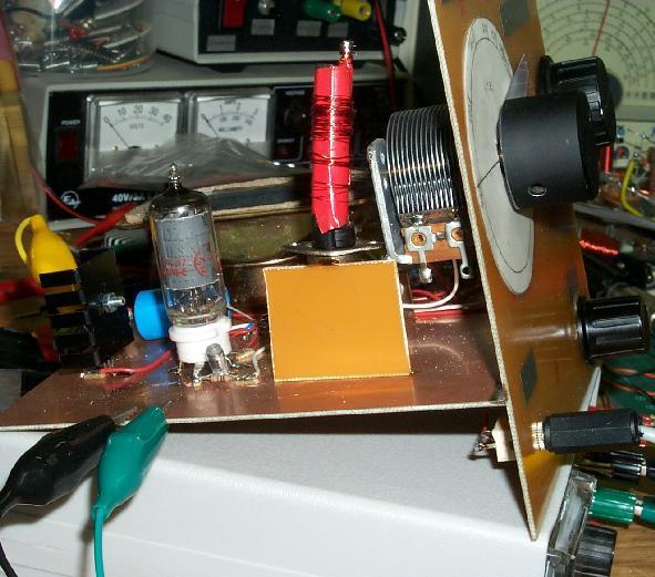
2 I built the prototype on a chunk of single sided unetched board (my favourite construction technique, a cross between ugly-bug and Manhattan). The coil was just a random bunch of turns on a film canister, it just happened to have holes in it from a previous project that were perfect for the tickler and tank winding lengths. The antenna coupling coil is just some turns wrapped around the resulting structure and soldered to the ground plane. The ferrite rods you can see are some random ones I picked up at DSE for $1 each. I have no idea what material they are, physically they are hard enough to blunt my hacksaw blades, and quite resistant to shattering, even when notched (they are like tungsten carbide or something, but more elastic. The only way I could cut them for a later coil was to clamp them in a vice and beat on them with a hammer until they shattered, hopefully at the right length). Whatever the designation of this ferrite, it is unlike any I have seen before, I must try to measure its properties some day. Here is a close-up of the prototype in a largely finished state, note the ugly 200p cap just dangling there in mid-air. I took the picture while I was finding out just where on the band it was working. The choke wound on the bolt is to prevent my PSU from oscillating. It has been playing up lately when connected to capacitive loads, I must fix it. Also note the little black things with three legs littering the board (well there is only two of them). I ran out of room to use another tube for the AF stage, so I resorted to transistors, and built around the tuning cap (it was an after-thought really). The amp stages are identical, fairly conventional AF designs with a gain of around 10dB each, I

3 have not included a circuit for them as they don't appear in the final version and you can replace them with you favourite building-block AF pre-amp. The just visible black thing that the AF lead heads off to is a small desktop amplified speaker. This arrangement provided enough gain to listen to DX stations while I built its daughter (the slightly better designed and more attractive version) This image comes from about half-way though the construction, the surfaces are unetched single-side PCB material with a solder fillet holding them together. I was concerned about its mechanical strength, but it is more than capable. The front panel has a largish knob for the tuning gang (a ~315p unit I purchased in a lot 20 from Antique Electronic Supply, another rapid shipment and very reasonable prices). There is also a smaller but still quite large knob for the regen control pot, and a medium knob for the AF gain pot. There is also a 3.5mm mono headphone jack, headphones being the main target output device, although the desk amp works well, and the internal speaker is OK for local stations, if a bit tinny because it has no resonant cavity. Just behind and to the left of the unit, the prototype is cluttering up my workspace, as I listen to some DX broadcast station (it is about 3 AM by now). It IDs as 'Radio 16 NTC' and I can hear other copies of its content elsewhere on the band, it plays country music. I am told this is a new network of country channels...
 LM1458 rather than an LF353, and the preamp stage has been")
4 Here is the almost complete unit. There is no finishing touches to the face plate yet, and the coil is still a temp' one I wound on the tube box. The AF amp in this unit is almost identical to the one in the desktop amp the unit is plugged into, except it uses a cheaper (and nastier) LM1458 rather than an LF353, and the preamp stage has been given more gain and a different frequency response. Note that I've added a 3 terminal regulator (the thing with the heatsink behind the speaker) so I can run the thing straight off my 15V PSU without reducing the heater life. You can probably see the tinning on the board near the big green-cap, I originally built the unit with a three-stage direct coupled AF amp (100dB design gain) but the rest of the circuit is too microphonic for that. The transistors I used in it were labelled BC549C, but they were pathetic, quite noisy and low gain. I used carbon resistors too, which only made things worse. Maybe some day I'll rebuild the amp using metal film resistors and good quality BC550Cs.

5
6 The finished product. The coil is socketed with a 5 pin DIN connector, allowing bandswitching. The tuning knob has a clear plastic needle overlay, and some 'dynamo' style labels have been added to the other front panel features. I haven't ripped the prototype apart either. It is a workable radio in its own right. I may recoil it for WWVH and build a rather power-hungry stratum-0 clock receiver for the local network. Source:
Starving Student II. Starving Student II. SS2 guide. Written By: 6L guides.diyaudio.com/ Page 1 of 24
 SS2 guide Written By: 6L6 2019 guides.diyaudio.com/ Page 1 of 24 INTRODUCTION This is a build guide for the hybrid headphone/pre-amplifier. You can buy a kit at the SSII product listing on the diyaudio
A Pretty Good Crystal Set Mark II
 A Pretty Good Crystal Set Mark II By Al Klase, N3FRQ, http://www.skywaves.ar88.net/ This is a revised version of the original New Jersey Antique Radio Club PGXS with minor changes to improve performance
A GOOD REGENERATIVE RECEIVER WITH SIMPLE FINE TUNING (2008)
") A GOOD REGENERATIVE RECEIVER WITH SIMPLE FINE TUNING (2008) A good SSB-CW-AM regenerative receiver with a fine tuning by moving the wooden stick with a grounded piece of PCB towards the coil. A good regenerative
A GOOD REGENERATIVE RECEIVER WITH SIMPLE FINE TUNING (2008) A good SSB-CW-AM regenerative receiver with a fine tuning by moving the wooden stick with a grounded piece of PCB towards the coil. A good regenerative
N3ZI Kits General Coverage Receiver, Assembly & Operations Manual (For Jun 2011 PCB ) Version 3.33, Jan 2012
 Version 3.33, Jan 2012") N3ZI Kits General Coverage Receiver, Assembly & Operations Manual (For Jun 2011 PCB ) Version 3.33, Jan 2012 Thank you for purchasing my general coverage receiver kit. You can use the photo above as a
N3ZI Kits General Coverage Receiver, Assembly & Operations Manual (For Jun 2011 PCB ) Version 3.33, Jan 2012 Thank you for purchasing my general coverage receiver kit. You can use the photo above as a
75 Meter SSB Project Design by KD1JV Built by Paul Jorgenson KE7HR NSS 39382FE
 75 Meter SSB Project Design by KD1JV Built by Paul Jorgenson KE7HR NSS 39382FE After completing a 75 meter DSB project (and using it underground, caving), I wanted to try building a SSB rig. I was searching
Read This Page First
 Read This Page First If you are reading this you know the manuals are always available at QRPKITS.com. This is version 8.0 of the manual dated 4/27/2016. There is no need to print out the whole assembly
The Walford Electronics Ford Receiver Kit Project Construction Manual
 The Walford Electronics Ford Receiver Kit Project Construction Manual Walford Electronics Ford Receiver construction manual V1.5 Page 1 of 22 Introduction The Ford receiver has four stages: The first stage
Minimalist Discrete Hi-Fi Preamp
 Minimalist Discrete Hi-Fi Preamp Rod Elliott (ESP) Introduction A preamp designed for the minimalist, and having no frills at all is the design goal for this project. It is designed as a preamp for the
VHF Super-Regenerative Receiver
 VHF Super-Regenerative Receiver I have started straight with the circuit out of the ARRL handbook, by Charles Kitchen N1TEV. I didn't have a 6v8 zener, or a few other part values, so I had to substitute
HT-1A Dual Band CW QRP Transceiver. Kit Building Instructions
 HT-A Dual Band CW QRP Transceiver Kit Building Instructions Rev B, July 8, 08 Designed by BD4RG Exclusively distributed by CRKITS.COM and its worldwide distributors Join the group http://groups.io/g/crkits
Step by Step Building PJ meter ARDF Receiver Kit. CRKITS.COM August 5, 2013
 Step by Step Building PJ-80 80-meter ARDF Receiver Kit CRKITS.COM August 5, 2013 What is ARDF? ARDF is the abbreviation of Amateur Radio Direction Finding, or so called Fox Hunting. If you are looking
ASSEMBLY MANUAL FOR R3500D DIRECTION FINDING RECEIVER KIT
 SDR-Kits www.sdr-kits.net SDR-Kits is CRKITS Authorised Distributor for Europe ASSEMBLY MANUAL FOR R3500D DIRECTION FINDING RECEIVER KIT Rev. A May 24, 2015 Written by CRKITS http://www.crkits.com Thanks
The Sudden Storm & Rexwood 1000W Kits. from QRPme. Builder s Guide. Version 6.2. for. Sudden Storm ][ ver.6 Rexwood 1000W ver.6. Updated 12/18/2017
![The Sudden Storm & Rexwood 1000W Kits. from QRPme. Builder s Guide. Version 6.2. for. Sudden Storm ][ ver.6 Rexwood 1000W ver.6. Updated 12/18/2017](/thumbs/89/98806822.jpg "The Sudden Storm & Rexwood 1000W Kits. from QRPme. Builder s Guide. Version 6.2. for. Sudden Storm ][ ver.6 Rexwood 1000W ver.6. Updated 12/18/2017") The Sudden Storm & Rexwood 1000W Kits from QRPme Builder s Guide Version 6.2 for Sudden Storm ][ ver.6 Rexwood 1000W ver.6 Updated 12/18/2017 Open the can and the adventure begins 1 Organize the parts
The Sudden Storm & Rexwood 1000W Kits from QRPme Builder s Guide Version 6.2 for Sudden Storm ][ ver.6 Rexwood 1000W ver.6 Updated 12/18/2017 Open the can and the adventure begins 1 Organize the parts
Assembly Instructions for the 1.5 Watt Amplifier Kit
 Assembly Instructions for the 1.5 Watt Amplifier Kit 1.) All of the small parts are attached to a sheet of paper indicating both their value and id. 2.) Leave the parts affixed to the paper until you are
I'm guessing this is what has made it so no one else could get the circuit to work, I hope this helps.
 Incase I did not mention this else where, the basis of my system to provide random audio bits which the spirits can use to form their voices. The audio bits are from randomly tuning a voltage tunable AM
SWL Receiving Antenna Experiments
 SWL Receiving Antenna Experiments Introduction I have a lot to learn about SWL antennas. What follows are some brief experiments I performed in late October 2005. I have been experimenting with a half
Homebrew and Experimenters Group HF Inductance Bridge (Compiled by VK2TOX)
") Homebrew and Experimenters Group HF Inductance Bridge (Compiled by VK2TOX) There are a number of ways to measure inductances used in construction of RF equipment. One of the most versatile ways is with
Homebrew and Experimenters Group HF Inductance Bridge (Compiled by VK2TOX) There are a number of ways to measure inductances used in construction of RF equipment. One of the most versatile ways is with
Ozark Patrol Assembly Manual
 Ozark Patrol Assembly Manual Copyright 2014 David Cripe NM0S The 4 State QRP Group Thank you for purchasing a Ozark Patrol kit. We hope you will enjoy building it and and find it a fun addition to your
Physics of the Electric Guitar
 Physics of the Electric Guitar Connections in Electricity and Magnetism First discovered by Michael Faraday, electromagnetic induction is the process of using magnetic fields to produce voltage, and in
FM RADIO KIT ESSENTIAL INFORMATION. Version 2.0 GET IN TUNE WITH THIS
 ESSENTIAL INFORMATION BUILD INSTRUCTIONS CHECKING YOUR PCB & FAULT-FINDING MECHANICAL DETAILS HOW THE KIT WORKS GET IN TUNE WITH THIS FM RADIO KIT Version 2.0 Build Instructions Before you start, take
SIMPLE DIRECT DRIVE DESULPHATOR/ DESULFATOR KIT INSTRUCTIONS
 SIMPLE DIRECT DRIVE DESULPHATOR/ DESULFATOR KIT INSTRUCTIONS Parts List C1 470uF/ 25V 1off C2 C5 0.1uF/ 50V 4off C6 C9 0.01uF/ 50V 4off D1 12V/ 1.3W zener 1off Q1 2N2907 1off Q2 Q4 IRFB3307 3off R1 510R/
1 TRANSISTOR CIRCUITS
 FM TRANSMITTERS The first group of circuits we will discuss are FM TRANSMITTERS. They can be called SPY TRANSMITTERS, FM BUGS, or a number of other interesting names. They all do the same thing. They transmit
Go back to the stopped deck. Put your finger on it, holding it still, and press start. The deck should be running underneath the stopped record.
 LEARN TO MIX RECORDS Place two identical records/cd's on your decks, and set the pitch to 0. On most decks, a green light will come on to let you know it's at 0 and it'll probably click into place. By
Mono Amplifier. LM386 Headphone Amp
 Mono Amplifier LM386 Headphone Amp Layout On/Off Switch - cuts power to the circuit Mono Input Jack: use either L or R or solder together Schematic Step 1 - Parts List 1.) R1-10ohm Resistor - Brown Black
the DON classics U76 (blue face - rev A) ASSEMBLY GUIDE REV: 1:04
 ASSEMBLY GUIDE REV: 1:04") the DON classics www.thedonclassics.com U76 (blue face - rev A) ASSEMBLY GUIDE REV: 1:04 QUICK ASSEMBLY GUIDE 9 STEPS TO COMPRESSOR HEAVEN! 1. 2. 3. 4. 5. 6. 7. 8. 9. Solder parts on PCB Wire pots Solder
the DON classics www.thedonclassics.com U76 (blue face - rev A) ASSEMBLY GUIDE REV: 1:04 QUICK ASSEMBLY GUIDE 9 STEPS TO COMPRESSOR HEAVEN! 1. 2. 3. 4. 5. 6. 7. 8. 9. Solder parts on PCB Wire pots Solder
Fun with Preamps A great way to pass a cold winter afternoon is to homebrew some preamps Designs and Benchmarks Construction The W7IUV Preamp
 Fun with Preamps A great way to pass a cold winter afternoon is to homebrew some preamps Built two preamps today. I ve been thinking of building a couple as a general interest project and today turned
Dual Digital Build Manual
 Dual Digital Build Manual Introduction This document is meant to aid you in assembling your Dual Digital Oscillator (DDO from now on). Some instructions may be a bit basic for advanced builders but I hope
SPRING REVERB datasheet ver. 17/01/17
 SPRING REVERB datasheet ver. 17/01/17 www.op-electronics.com Printing error: last datasheet revision contained a mistake about the value of C5 capacitor, the cap value should be 680p and not 47n. This
K1EL 75 Meter AM Phone Receiver AMR75
 Features 3.8MHz Amateur Phone Band Receiver 100 KHz Tuning Range Wideband Hi-Fi AM mode reception Single Sideband mode with on board BFO Uses single chip TRF TA7642 IC Low impedance 8 ohm speaker output
A 100-Watt Transmitter Using a Pair of VT1625s
 12/16/2007 6:00 PM VT1625 100 Watt Transmitter A 100-Watt Transmitter Using a Pair of VT1625s FIG. 10.6 A 100-watt transmitter for five bands, using salvaged TV power transformer and surplus 1625 amplifier
Congratulations! We think you made a great choice with the '30 in 1' Electronic Projects Lab Kit from Quasar Electronics.
 Quasar Electronics Order Code EPL030 Features Congratulations! We think you made a great choice with the '30 in 1' Electronic Projects Lab Kit from Quasar Electronics. This kit is like an "instant electronics
GRID DIP METER DESIGN
 GRID DIP METER DESIGN BY G0CWA MAY 2013 This, my next offering of test equipment is an exceptionally useful item of test equipment with many uses, some are listed below. To coin a phrase given to me by
TV Remote. Discover Engineering. Youth Handouts
 Discover Engineering Youth Handouts Electronic Component Guide Component Symbol Notes Amplifier chip 1 8 2 7 3 6 4 5 Capacitor LED The amplifier chip (labeled LM 386) has 8 legs, or pins. Each pin connects
Simple LFO Features. 2. Application. 3. Description. Simple and easy to build LFO module for Analog Synthesizers.
 Simple LFO. Simple and easy to build LFO module for Analog Synthesizers.. Features Square and Triangle waveforms (90 phase shifted) Dual range frequencies Frequency ranges from under Hz up to several khz
How to build a Cracklebox. Red Wierenga Brooklyn College Center for Computer Music October 13, 2015
 How to build a Cracklebox Red Wierenga Brooklyn College Center for Computer Music October 13, 2015 What s a Cracklebox? What s a Cracklebox? The Cracklebox was developed by Michel Waisvisz and others at
BITX40 with Raduino - tips and mods
 BITX40 with Raduino - tips and mods Also check out hfsigs blogspot http://bitxhacks.blogspot.co.uk/ Clicks during tuning I assume you are talking about the Raduino clicking as you tune. I'm not having
BMC055. Sallen-Key Voltage Controlled Filter Last updated
 BMC055. Sallen-Key Voltage Controlled Filter Last updated 0-6-208 If you have any questions, or need help trouble shooting, please e-mail Michael@Bartonmusicalcircuits.com I What The Knobs And Jacks Do
Electric Druid Flangelicious Flanger Project
 Electric Druid Flangelicious Flanger Project (Using either 4KNOBFLANGE or MULTIFLANGE chips) Overview! 2 Build Instructions! 2 Populate the PCB! 2 1N4148 Diodes! 2 Resistors! 2 Cup of tea and soldering
BassAce - Midi Bass Synthesizer. BassAce Features
 Untitled Document BassAce - Midi Bass Synthesizer The BassAce is a small midi-synth based loosely on the TB303. It can be built many different ways. Depending on how it's configured it can be anything
Vintage Radio Alignment: What It Is and How to Do It
 Vintage Radio Alignment: What It Is and How to Do It Copyright 2009 Bret s Old Radios Bret Menassa Member: ARCI, VRPS, OKVRC Presented at Radiofest 2009, Willowbrook,, IL Vibrations A musical instrument
Simple Loop Antennas By TWR Bonaire Engineering
 Improving Medium Wave Reception Simple Loop Antennas By TWR Bonaire Engineering Dave Pedersen dpedersen@twr.org The Problem with listening to distant medium wave radio stations Radio stations on the Medium
Assembly Instructions for the FRB FET FM 70 Watt Amp
 Assembly Instructions for the FRB FET FM 70 Watt Amp 1.) Orient the circuit board with the diagram 2.) Use a narrow chisel tip 25-30 watt soldering iron for assembly 3.) All the small parts are taped onto
SPECIFICATIONS: Subcarrier Frequency 5.5MHz adjustable, FM Modulated +/- 50KHz. 2nd 11MHz >40dB down from 5.5MHz
 Mini-kits AUDIO / SUBCARRIER KIT EME75 Version4 SPECIFICATIONS: Subcarrier Frequency 5.5MHz adjustable, FM Modulated +/- 50KHz Subcarrier Output 1.5v p-p Output @ 5.5MHz DESCRIPTION & FEATURES: The Notes
A 1951 Beginner/Novice Station
 A 1951 Beginner/Novice Station Introduction In 1951 "The Roy Rogers Show," "I Love Lucy" and "Mr. Wizard" were all new to television. In 1951 General Douglas MacArthur, relieved of his duties by President
MZ2 HEADPHONE AMPLIFIER, PREAMP, & STEREO AMPLIFIER USER GUIDE
 MZ2 HEADPHONE AMPLIFIER, PREAMP, & STEREO AMPLIFIER USER GUIDE Linear Tube Audio Takoma Park, MD, USA WARNING: For safety, the cover of this amplifier should be secured at all times. DC voltages as high
Build an All-Tube Fuzz/Wah Pedal
 Build an All-Tube Fuzz/Wah Pedal by Eric Barbour and Peter Belov In spite of more than 30 years of development and marketing, to this day all commercial guitar "wah" pedals have been solid- state and have
THE 1956 ZENITH ROYAL 500 TRANSISTOR OWL S EYES RADIO.
 THE 1956 ZENITH ROYAL 500 TRANSISTOR OWL S EYES RADIO. Dr. H. Holden. Feb. 2018. Introduction: The Zenith Royal 500 radio appeared in 1956, two years later than the Regency TR1 which was the first commercial
ILER-40 AGC "ADD-ON" MINI-MODULE Last review November 1, 2012
 ILER-40 AGC "ADD-ON" MINI-MODULE Last review November 1, 2012 ea3gcy@gmail.com Latest updates and news: www.qsl.net/ea3gcy PLEASE READ ALL INSTRUCTIONS COMPLETELY AT LEAST ONCE BEFORE STARTING. Installation
HOM rev. new. Heath of the Month #80 - K-1 All-Wave Receiver. Heathkit of the Month #80: by Bob Eckweiler, AF6C AMATEUR RADIO - SWL
 Heathkit of the Month #80: by Bob Eckweiler, AF6C AMATEUR RADIO - SWL The Heathkit K-1 Three-Tube All-Wave Beginner s Receiver Some K-1 All-Wave Receiver History: The first piece of radio equipment using
The Electro-Magnetic Spectrum
 The Electro-Magnetic Spectrum Part Three In This Issue: All about Tubes How a diode rectifier works How a triode amplifier works How the mixer in your receiver works Dear Friends: For quite some time I
MARTIN - G8JNJ ECLECTIC AETHER - ADVENTURES WITH AMATEUR RADIO
 MARTIN - G8JNJ ECLECTIC AETHER - ADVENTURES WITH AMATEUR RADIO REDUCING RTL DONGLE INTERNAL SPURII AND NOISE SIGNALS I ve recently bought quite a few RTL DVB-T RTL 2832U / Rafael Micro R820T dongles to
S-Pixie QRP Kit. Student Manual. Revision V 1-0
 S-Pixie QRP Kit Student Manual Revision V 1-0 Introduction The Pixie 2 is a small, versatile radio transceiver that is very popular with QRP (low power) amateur radio operators the world over. It reflects
Building and Operating: LF Converter An SA612 based LF up-converter from Jackson Harbor Press
 Introduction: Building and Operating: LF Converter An SA612 based LF up-converter from Jackson Harbor Press The frequencies below the broadcast band are covered by few receivers on the market - those that
This project is available on 3 different PC boards: Diesel Sound 1 -long board. Diesel Sound 2 -short board
 This project is available on 3 different PC boards: Diesel Sound 1 -long board Diesel Sound 2 -short board Diesel Sound 3 - called Diesel Sound 4 watt The tiny Diesel Sound Generator easily fits into this
Dentron Clipperton L Conversion to GI-7B Tubes and Other Modifications. Pat Griffin AA4PG
 Dentron Clipperton L Conversion to GI-7B Tubes and Other Modifications Pat Griffin AA4PG Walking out of Dayton, 2014 my eye caught a beat up Clipperton cabinet under a vendor table. Twenty bucks and it
G3EJS portable antenna for the IC-703
 G3EJS portable antenna for the IC-703 Following a comment I have received several emails reqesting details of my antenna, so I have very quickly put this together, not very good, but sufficient for anyone
Physics of Music Projects Final Report
 Physics of Music Projects Final Report John P Alsterda Prof. Steven Errede Physics 498 POM May 15, 2009 1 Abstract The following projects were completed in the spring of 2009 to investigate the physics
1. PCB and schematic
 1. PCB and schematic 2. Assembly manual WHAT'S IN THE BOX 1 x PCB tape: o 5 x jumper o 6 x resistor 1K o 12 x resistor 10K o 1 x resistor 15K o 8 x resistor 100K o 2 x resistor 47K 4 x 14p IC socket 4
MONO AMPLIFIER KIT ESSENTIAL INFORMATION. Version 3.0 CREATE YOUR OWN SPEAKER DOCK WITH THIS
 ESSENTIAL INFORMATION BUILD INSTRUCTIONS CHECKING YOUR PCB & FAULT-FINDING MECHANICAL DETAILS HOW THE KIT WORKS CREATE YOUR OWN SPEAKER DOCK WITH THIS MONO AMPLIFIER KIT Version 3.0 Build Instructions
ECE 203 ELECTRIC CIRCUITS AND SYSTEMS LABORATORY SPRING No labs meet this week. Course introduction & lab safety
 ECE 203 ELECTRIC CIRCUITS AND SYSTEMS LABORATORY SPRING 2019 Week of Jan. 7 Jan. 14 Jan. 21 Jan. 28 Feb. 4 Feb. 11 Feb. 18 Feb. 25 Mar. 4 Mar. 11 Mar. 18 Mar. 25 Apr. 1 Apr. 8 Apr. 15 Topic No labs meet
Standard Kit #1 (5-way switch)
") Standard Kit #1 (5-way switch) Please Read All Instructions Before Beginning. Tools you will need: Soldering Iron (35 watt preferably) Solder Wet Sponge Wire Clippers 3/8 Drill Bit 1/4 Drill Bit Variable
Standard Kit #1 (5-way switch) Please Read All Instructions Before Beginning. Tools you will need: Soldering Iron (35 watt preferably) Solder Wet Sponge Wire Clippers 3/8 Drill Bit 1/4 Drill Bit Variable
Take another look at the Noise Bridge:
 Take another look at the Noise Bridge: Author K.P.Barnsdale ZL3KB Date 21 October 1998 Diagrams: 1. Circuit diagram. 2. PCB layout 3. Front panel layout 4. Internal layout diagram 5. Inductance chart Introduction
Instructions for Building the Pulsed Width Modulation Circuit. MC-12 (DC Motor Controller or PWM) From Electronic Light Inc. (revised kit 10/03/08)
 From Electronic Light Inc. (revised kit 10/03/08)") Instructions for Building the Pulsed Width Modulation Circuit MC-12 (DC Motor Controller or PWM) From Electronic Light Inc. (revised kit 10/03/08) Congratulations on your purchase of the MC-12 DC Motor
Instructions for Building the Pulsed Width Modulation Circuit MC-12 (DC Motor Controller or PWM) From Electronic Light Inc. (revised kit 10/03/08) Congratulations on your purchase of the MC-12 DC Motor
ALX-SSB 5 Band Filter Assembly Manual 19 November 2018
 ALX-SSB 5 Band Filter Assembly Manual 19 November 2018 Contents Theory of Operation:... 1 Figure 1... 2 Parts Included:... 4 Board Overview:... 5 Figure 2... 5 Figure 3... 5 Board Assembly:... 6 Cable
Valve Junior Modification
 Valve Junior Modification Rob Marshall Spring 2010 Physics of Musical Instruments Table of Contents Pages 1 2...Information about the amplifier Pages 3 4...Modifications made Page 5 7...Replacement of
The Amazing All-Band Receiver
 The Amazing All-Band Receiver The Amazing All-Band Receiver is basically a diode detector followed by a high-gain audio amplifier. The detector uses a biased Schottky diode for excellent sensitivity and
MFJ-219/219N 440 MHz UHF SWR Analyzer TABLE OF CONTENTS
 MFJ-219/219N 440 MHz UHF SWR Analyzer TABLE OF CONTENTS Introduction...2 Powering The MFJ-219/219N...3 Battery Installation...3 Operation Of The MFJ-219/219N...4 SWR and the MFJ-219/219N...4 Measuring
Building the Sawdust Regenerative Receiver
 Building the Sawdust Regenerative Receiver Introduction The Sawdust is a super regenerative receiver using the basic Armstrong design architecture. The receiver uses one toroidal transformer to provide
Assembly Manual V1R2B-Rev1.0D
 Assembly Manual V1R2B-Rev1.0D for 4 State QRP MagicBox - Solid State Transmit/Receive System Designed by: Jim Kortge, K8IQY Copyright 2009-2012 - All rights reserved This system is the result of some brainstorming
Elmer Session Hand Out for 3/3/11 de W6WTI. Some Common Controls Found On Amateur Radio Transceivers. (From ARRL web site tutorial)
") Elmer Session Hand Out for 3/3/11 de W6WTI Some Common Controls Found On Amateur Radio Transceivers. (From ARRL web site tutorial) The placement of the controls may vary from manufacturer to manufacturer
Elmer Session Hand Out for 3/3/11 de W6WTI Some Common Controls Found On Amateur Radio Transceivers. (From ARRL web site tutorial) The placement of the controls may vary from manufacturer to manufacturer
Parallel Port Relay Interface
 Parallel Port Relay Interface Below are three examples of controlling a relay from the PC's parallel printer port (LPT1 or LPT2). Figure A shows a solid state relay controlled by one of the parallel port
Triode Dick's Page. TentLabs filament supply. ...to apply with directly heated tubes
 Triode Dick's Page TentLabs filament supply...to apply with directly heated tubes A pleasant surprise A while ago I received a package with a pair of neat modules, with regards from Guido Tent, who runs
KN-Q10 Assembly Manual
 KN-Q10 Assembly Manual Translated by Adam Rong, BD6CR/4 with permission from Ke Shi, BA6BF Edited by Stephen, VK2RH Revision B, Oct 14, 2010 Thank you for purchasing the KN-Q10 4 Band SSB/CW Dual Mode
The 6LE8 One Tube Broadcaster
 The 6LE8 One Tube Broadcaster Introduction The purpose of this broadcaster is to transmit your favorite music to every AM radio in your home. The transmitting power is so low that it should not bother
New Life for the AM6154 and AM6155 John, W1AN 29 July, 2014
 New Life for the AM6154 and AM6155 John, W1AN 29 July, 2014 There are numerous sources for conversion information and modifications that have been shared over the years for the FAA AM6154 and AM6155 amplifiers
AMP CAMP AMP #1. Introduction. Requirements and Constraints. by Nelson Pass
 AMP CAMP AMP #1 by Nelson Pass Introduction Do-It-Yourself audio is a great activity. Many major audio components are easily constructed and made to perform as well or better than what we see in the stores
ATUs - ANTENNA TUNING UNITS THE ATU. An Antenna Tuning Unit MAKE YOUR OWN ATU
 ATUs - ANTENNA TUNING UNITS THE ATU An Antenna Tuning Unit MAKE YOUR OWN ATU The circuit diagram below shows the circuit for a typical Pi type ATU which seems to be a popular arrange ment for many ATUs.
Source: IC Layout Basics. Diodes
 Source: IC Layout Basics C HAPTER 7 Diodes Chapter Preview Here s what you re going to see in this chapter: A diode is a PN junction How several types of diodes are built A look at some different uses
How to use your antenna tuner.
 How to use your antenna tuner. There's more to it than what is in your manual or on most how to do it websites! http://www.arrl.org/tis/info/ant-tuner-op.html Here is a neat site with a "T" network simulator.
Construction Guide European Version
 Construction Guide European Version PCB This section describes how to build up the DRO-350 printed circuit board (PCB). The bare PCB is available for purchase on the order page. Static Protection Bare
QRPme Crystal Checker Kit Featured in FDIM 2011 Build-Along
 QRPme Crystal Checker Kit Featured in FDIM 2011 Build-Along This crystal checker circuit was first presented in a workshop given by WA3OPY, AC5UR & W1REX a few years ago at the 4 States QRP Club gathering
CALRAD 25 series - potentiometers
 25 series - potentiometers audio /linear SUB-MINIATURE VOLUME CONTROLS Linear taper, extremely smooth for quiet operation. 1 2" dia. fits into 1 4" hole. Shaft 3 16" dia. Thread length 7 32", shaft length
INDUCTION BALANCE Murray/Modern Magazines, reproduce for personal use only METAL DETECTOR
 Project 549 INDUCTION BALANCE Murray/Modern Magazines, reproduce for personal use only METAL DETECTOR A really sensitive design operating on a different principle from that of other published circuits.
Congratulations on your purchase of the SparkFun Arduino ProtoShield Kit!
 Congratulations on your purchase of the SparkFun Arduino ProtoShield Kit! Well, now what? The focus of this guide is to aid you in turning that box of parts in front of you into a fully functional prototyping
Pacific Antenna Low Pass Filter Kit
 Pacific Antenna Low Pass Filter Kit Description Many basic transmitter and/or transceiver designs have minimal filtering on their output and frequently have significant harmonic content in their signals.
Building The DC Beeper from Jackson Harbor Press A Morse code voltmeter / DC switch
 Building The DC Beeper and from Jackson Harbor Press Operating A Morse code voltmeter / DC switch The DC Beeper kit is a combination of a Morse code voltmeter with 20 mv resolution and a DC switch. The
Instructions for Building the Pulsed Width Modulation Circuit. MC-12 (DC Motor Controller or PWM) From Electronic Light Inc. (revised kit 8/08)
 From Electronic Light Inc. (revised kit 8/08)") Instructions for Building the Pulsed Width Modulation Circuit MC-12 (DC Motor Controller or PWM) From Electronic Light Inc. (revised kit 8/08) Using this circuit for a pulsed DC current to your cell. Do
Instructions for Building the Pulsed Width Modulation Circuit MC-12 (DC Motor Controller or PWM) From Electronic Light Inc. (revised kit 8/08) Using this circuit for a pulsed DC current to your cell. Do
Component Identification
 Generic Skills for Microelectronic Engineers Component Identification AIM: To be able to identify common electronic components used in miniature and medium power applications. Methods of labelling, range
40106 Hex Oscillator Workshop Instructions. bbob drake, aka fluxmonkey
 40106 Hex Oscillator Workshop Instructions bbob drake, aka fluxmonkey 40106 Hex Oscillator Workshop Instructions by Bbob Drake is licensed under a Creative Commons Attribution-ShareAlike 4.0 International
SpikerBox v1.3 DIY Instructions
 SpikerBox v. DIY Instructions Prepare yourself. In hours, you will have built your own SpikerBox to begin doing neuroscience and whatever your creative mind can conjure. Materials Needed:. A Backyard Brains
MP573 Assembly guide. Soldering. MP573 Assembly guide PCB split PCB split. Document revision 2.2 Last modification : 22/08/17
 MP573 Assembly guide Safety warning The kits are main powered and use potentially lethal voltages. Under no circumstance should someone undertake the realisation of a kit unless he has full knowledge about
Simple EL84 Basic layout. DIY Paradise 13 June 2003
 Simple EL84 Basic layout DIY Paradise 13 June 2003 EL84 doesn t sing without feedback. EL84 has no bass. These are comments I gleamed off the World Wide Web from various places. The truth is, if the circuit
Foxhunt Offset Attenuator. Parts List:
 When your closing in on the fox you may find the signals to be so strong that you can no longer find a peak or null with your antenna. Sometimes the signal is so strong that the RF will leak straight into
Cricket 80a Assembly Manual v Copyright David Cripe NM0S The 4 State QRP Group
 Cricket 80a Assembly Manual v. 1.0 Copyright 2017 David Cripe NM0S The 4 State QRP Group Introduction Thank you for purchasing a CRICKET 80a Transceiver. We hope you will enjoy building it and find it
Building the Sawdust Regenerative Receiver
 Building the Sawdust Regenerative Receiver Introduction The Sawdust is a super regenerative receiver using the basic Armstrong design architecture. The receiver uses one toroidal transformer to provide
Eo Classical - Specification and Features
 Eo Classical - Specification and Features Folded dimensions 420mm long x 100mm high x 130mm wide. Weight 1.5 kg. Unfolded, overall 820 mm x 360 mm with contour wings in place. String scale length: 650
THE INTERMEDIATE VFO
 THE INTERMEDIATE VFO Some Intermediate tutors have reported difficulties in either obtaining parts for the RSGB Intermediate textbook VFO or in getting the VFO going once they have the parts. This alternative
Standard Kit #1 (3-way switch)
") Standard Kit #1 (3-way switch) Please Read All Instructions Before Beginning. Tools you will need: Soldering Iron (35 watt preferably) Solder Wet Sponge Wire Clippers 3/8 Drill Bit 1/4 Drill Bit Variable
Standard Kit #1 (3-way switch) Please Read All Instructions Before Beginning. Tools you will need: Soldering Iron (35 watt preferably) Solder Wet Sponge Wire Clippers 3/8 Drill Bit 1/4 Drill Bit Variable
Technical Bulletin A Versatile Pulse Tester Page 1 of 6
 Technical Bulletin A Versatile Pulse Tester Page 1 of 6 A Versatile Pulse Tester By G8MNY (BATC's CQTV No 195, Updated Oct 07) (8 Bit ASCII Graphics use code page 437 or 850) This tester based on ideas
CW-ADD. Universal CW Adapter for SSB Transceivers. Assembly manual. Last updated: October 1,
 CW-ADD Universal CW Adapter for SSB Transceivers Assembly manual Last updated: October 1, 2017 ea3gcy@gmail.com Updates and news at: www.ea3gcy.com Thanks for building the Universal CW Adapter kit CW-ADD