Features, Benefits, and Operation
|
|
|
- Janis Norman
- 5 years ago
- Views:
Transcription

1 Features, Benefits, and Operation 2013 Decibel Eleven
2

3 Features, Benefits, and Operation Contents Introduction... 2 Features... 2 Top Panel Controls... 3 Operation Basics... 4 Connections... 5 Rear Panel Diagram... 7 True Bypass... 8 Series Connection... 8 Order Swapping... 9 Parallel Mix Bus Tails Control Buffering Operating Modes Preset Control MIDI Control Settings Mode...17 MIDI Sysex Data Dump Specifications Declaration of Conformity Decibel Eleven declares that this product complies with the European Union Council Directives and Standards requirements for the Low Voltage Directive (2006/95/EC) and the EMC Directive (2004/108/EC) Decibel Eleven 1
4 Introduction The Pedal Palette, at it's core, is a four loop, true bypass switcher designed to preserve guitar tone and signal when pedal effects are bypassed. It features the ability to store and recall preset combinations of pedals, enabling the user to switch multiple pedals in and out of the effect chain simultaneously with a single button press. In addition to these base features, the Pedal Palette expands your sonic palette by adding an available parallel mix bus to all effect returns, and adding the ability to change the order of the effects on the fly. The Pedal Palette is a creative tool designed with an intuitive user interface, making experimentation simple and easy. Reading the entire manual is not necessary to begin enjoying the benefits of the Pedal Palette, but it is highly recommended for a full understanding of it's features and operation. Features 4 Pedal Effects Loops True Relay Bypass Fully Analog Signal Path Swap Pedal Order Instantly Blend any effect in Parallel Reverb and Delay Tails Control Optional Discrete Class A Input Buffer 128 Presets Send and Receive MIDI Program changes Website Go to decibel11.com for videos, manuals, accessories, and more. Contact us directly at support@decibel11.com. 2
5
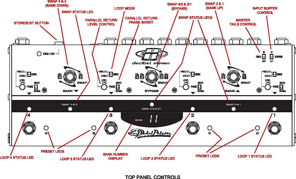
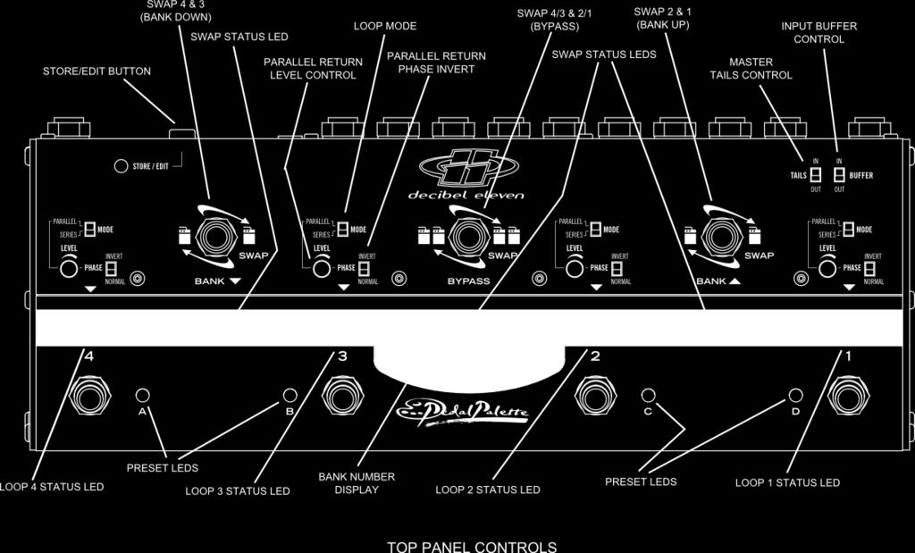
6 Operation Basics This section describes the basic controls of the Pedal Palette. It is meant as a general introduction and a guide for those wanting to get started immediately. This section only covers DIRECT MODE functionality, which is the factory set default mode. For PRESET MODE operation, see the Preset Control section [page 14]. Loop Mode Settings Each loop can be configured to have either a series or parallel connection. Use the MODE switch to select the desired mode. When the loop is in PARALLEL mode, it's return signal can be blended, or mixed, into the Pedal Palette signal path using the LEVEL knob and the PHASE switch. For more information on loop modes, see the Series Connection and Parallel Mix Bus sections [page 8 & 10]. NOTE: Changing the MODE settings can cause a loud click or snap with high gain amplifiers. It is advised to keep volume low when switching these. Controlling the Loop States The bottom row footswitches (1-4) are used to turn the loops on or off. Status is indicated by the RED LED directly above the switch. Swapping the Loop Order The top row footswitches are used to swap the order of the effects. The right-most footswitch will reverse the order of loops 1 & 2 when activated. It's status is indicated by the YELLOW LED directly below the footswitch. The left-most footswitch will reverse the order of loops 3 & 4 when activated. The center footswitch reverses the order of the loop 1&2 section and the loop 3&4 section when activated. For more information on swapping, see the Order Swapping section [page 9]. Input Buffer When the BUFFER switch in the upper right corner is set to IN, the input buffer is active in circuit. Setting the switch to OUT will bypass the input buffer circuit. For more details on how Pedal Palette buffers work, see the Buffering section [page 13]. Tails Control The TAILS switch in the upper right corner is the master setting for tails control. When this switch is set to IN with at least one loop in parallel mode, the parallel mix bus circuit is always active. With the switch OUT, the parallel mix bus is only active when a parallel mode loop is turned ON. For additional control, loops can be individually configured for tails in or out [see Tails Control section page 12]. 4


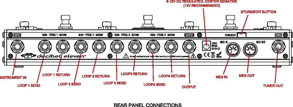
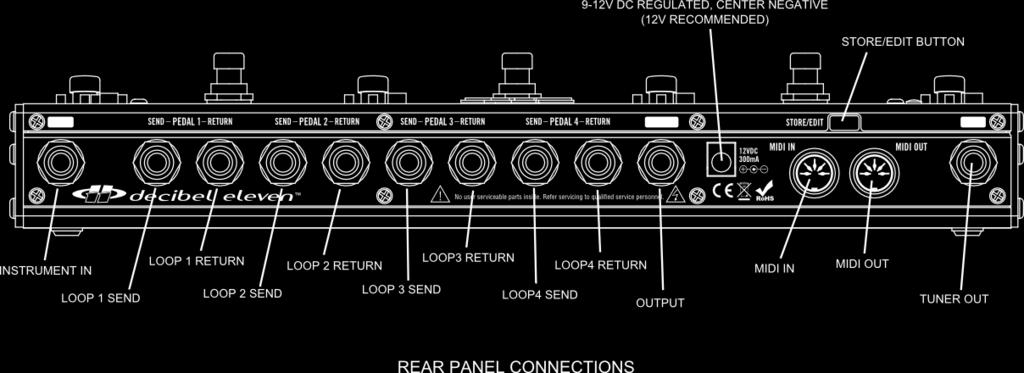
7 Storing a Preset A loop combination can be stored as a preset by pressing and holding the STORE/EDIT button. The green STORE/EDIT LED will light, a bank number will be displayed, and the BLUE preset LEDs will flash in sequence. Select the preset location to store to by first using the BANK UP and BANK DOWN switches to select the desired bank, and then using the bottom row footswitches to select the preset location (A-D) within the bank. Once the Bank/Preset combination is selected, press the STORE/EDIT button again to save the preset and return to normal operation. For more details, see the Preset Control section [page14]. Connections Refer to the drawings below and to the REAR PANEL CONNECTIONS figure on page 7. Each loop of the Pedal Palette can accommodate one or more effect pedals. The SEND jack of each loop is connected to the input of the pedal for that loop. If more than one pedal is used in the loop, then connect the SEND to the input of the first pedal in the loop. Connect the output of the pedal (or last pedal if more than one pedal is used in a loop) to the RETURN jack. Connect your instrument to the INPUT jack, and connect the OUTPUT jack to the amplifier, additional pedal, or other destination. The Pedal Palette can also be used in the effect loop of an amplifier for parallel mixing of modulation pedals within the amp's loop. The TUNER jack can be used for always on tuning. Power The Pedal Palette can be powered by 9VDC or 12VDC at 300mA. It is highly recommended that a well regulated and isolated 12V, 300mA (minimum) power supply is used for best performance. The power inlet jack is a standard 2.1mm DC power jack, center negative connection. Simple setup with one pedal per loop 5


8 Expanded setup with optional multiple pedals per loop and MIDI Pedal Palette in Amplifier's Effect Loop Multiple Modulation Effects in Parallel Expanded setup using two Pedal Palettes 6
9
10 True Bypass Passive guitar pickups are low level, high impedance sources. This means they are easily loaded down by all the various cable and connections required when using multiple effect pedals, resulting in a loss of high frequency response. Many effect pedals on the market employ circuitry that is active even when the effect is turned off. While this design allows for silent switching, the bypass circuitry typically has high harmonic distortion and minimal headroom, both of which can greatly affect the tone and dynamics of your playing. Other pedal designs use a bypass scheme where the effect's input circuitry remains connected even when bypassed. This type of pedal continues to load the guitar signal even when the pedal is switched off. These types of pedal bypass issues have a cumulative effect. And, with several pedals in your effect chain, they can result in a loss of tone, dynamics, and high frequency response - even when all your pedals are OFF. A true bypass pedal will completely disconnect all circuitry from the guitar signal and will route the pedal input directly to the pedal output. This provides the most pure signal path. However, even if all the pedals in your effect chain are true bypass, there still exists the possibility of poor signal caused by all of the cables, connectors, and switches that your guitar signal must travel through. The Pedal Palette is a true bypass switcher. The advantage to having all of your effect pedals connected through the Pedal Palette is that, when all of the pedal loops are switched off, your guitar signal goes directly from the input jack to the output jack, bypassing all of the cables, connectors and pedals in the effect chain.* In order to achieve a straight wire type of true bypass, the Pedal Palette utilizes relays. This provides the most transparent bypass possible. However, because relays are mechanical switches, it is understood that they inherently cause some noise when switching. * when the Input Buffer and Tails switches are off. Series Connection Guitar effect pedals are typically wired in what is known as a series configuration. What this means is that the guitar is plugged into the first pedal, the output of the first pedal goes to the input of the second pedal, the output of the second pedal goes into the third pedal, etc. [see Figure 1]. This configuration makes it simple and easy to see what the signal path is. However, the series configuration is limited in several ways. The series order of the effects is fixed and cannot be 8


11 changed. And, the effects cannot be blended or mixed. Digital multi-effect processors have long been able to obtain more complex and flexible routing and mixing capabilities. And, recording engineers will often use multiple effects mixed in parallel to create lush and complex soundscapes. With the Pedal Palette it is now possible to obtain these types of results with analog routing and mixing for your favorite pedal effects. Order Swapping Typically, the order of your pedals in your effect chain is determined by trial and error, and through general consensus. However, many times an alternate order of pedals can result in an equally useful and effective sound effect. The Pedal Palette gives you the ability to swap the order of your effects in real-time. In some cases, this can result in drastic differences. This is particularly true with tone or frequency modifying effects such as distortion, wah, or EQ pedals. In other cases, the result is more subtle, where one effect becomes more predominate than the other(s). Modifying effect pedal order is great when searching for just the right sound, and it greatly expands your available sonic options. The top row of footswitches, labeled SWAP, allow the order of the effects to be changed. The rightmost SWAP switch reverses the order of loops 1&2. The left-most SWAP switch reverses the order of loops 3&4. The middle SWAP switch reverses the order of the loop 1&2 section and the loop 3&4 section [see Figure 2]. This method allows many possible order combinations while still being intuitive and easy to understand. The YELLOW swap status LEDs provide simple visual feedback, making it ideal when swapping live and in real time. 9

12 Parallel Mix Bus Parallel mixing has long been a useful method of achieving a desired sound effect. It is a standard method used with reverbs and delays. All reverb and delay pedals have some type of parallel mixer built into them. The signal seen at the input to the effect, referred to as the dry signal is mixed with the delayed output of the effect (the wet signal). Some pedals convert the direct dry signal to digital and mix it with the wet signal digitally before converting back to analog. Other pedals keep the direct dry signal analog and mix analog. In many cases the mix is controlled through a blend knob which balances the amount of dry signal with the amount of effected wet signal. The parallel mix bus in the Pedal Palette works in a similar way, by taking the pedal's output at the loop return jack and mixing it with the dry signal obtained within the Pedal Palette. In this case, however, since the Pedal Palette has more than one effect (loop), the dry signal is not always the signal at the input jack. It could also be the signal output from any active SERIES mode loop(s). Setting a Loop in Parallel Mode To configure a loop in parallel, set the loop MODE slide switch to PARALLEL. Once the switch is set to PARALLEL, the loop's send signal is split and also sent to the following loop's send jack. The return signal of the loop will now be routed to the parallel mix bus instead of to the next loop's send. See Figure 3 below showing the signal routing when a loop is in parallel. Level and Phase Invert Controls When a loop is set to PARALLEL mode, there are two additional controls which can be used to set the desired blend of the effect. The LEVEL control is used to set the amount of effect return that is mixed in. The PHASE switch inverts the phase of the effect return. Some effect pedals will invert the phase of the signal such that their output is out of phase with their input. With these types of effect pedals, it will be necessary to use the INVERT position to correct the phase before mixing. Other pedals may have some phase shift, but may not be completely out of phase. For these reasons, some 10
13 experimentation with the PHASE switch settings is recommended. If the effect gets weaker when the LEVEL control is turned all the way clockwise, this is an indication that the effect is out of phase, and the PHASE switch should be toggled. In any case, use what sounds best. Parallel Reverb and Delay There are several practical advantages to using the Pedal Palette with delay and reverb pedals: The direct guitar signal remains analog. Since your dry sound is no longer obtained from the effect pedal, your guitar signal will not be converted to digital and back again (as some pedals do). Also, your dry guitar signal level remains consistent and it is not modified and re-mixed at each reverb and delay pedal in the chain, which can add noise. Delay and reverb tails, or echoes, can continue to decay naturally after the effect is switched off. Delay and reverb pedals that are true bypass must abruptly cut-off the reverb and delay tails when switched off. With the Pedal Palette, their echo tails are allowed to fade out [see Tails Control section page 12]. Multiple delay and/or reverb pedals active in an effects chain can all be fed the same input signal. Using both a delay and a reverb on a source is a common technique in recording studios. However, the same result can not be achieved in a typical series pedal effect chain. This is because, in the series chain, one of the two effects must always come first, putting it's imprint on the sound before reaching the second effect. With the Pedal Palette, it is now possible to send the same input signal to both the reverb and delay effects, and then mixing their wet outputs together with the dry signal using the parallel mix bus. When using delay and reverb pedals in PARALLEL mode with the Pedal Palette, it is important to set the blend or mix setting on the pedal(s) to 100% wet. The blending will now be controlled with the loop's LEVEL control on the Pedal Palette. In some pedals, there may be an internal setting for kill dry which can also achieve the same result. Creative Uses of Parallel Mixing Parallel effects mixing is widely used in recording studios as a creative tool for blending all types effects to achieve a more distinctive soundscape. Many of these same techniques can be applied using guitar pedal effects with the Pedal Palette. For example, the intensity of a chorus or flanger can be easily controlled by using a parallel mix bus to blend the amount of effected signal with the direct signal. Mixing a compressor in parallel can fatten the sound, while still retaining dynamics, by blending the direct tone with a heavily compressed tone. Likewise, a distortion pedal can be blended 11

14 with a clean tone to create a bigger, more dynamic sound. When used in combination with effects order swapping, the parallel mix bus can yield some interesting results. Many times, parallel mixed effects, such as delay, are used at the end of the chain. This allows additional series effects to be inserted in front of it, with the result being that the delay receives the affected sound. In the Pedal Palette, if the order is swapped, the result is that the delay is now fed the clean guitar signal and the series effect is also fed the clean guitar signal, creating a dual signal path. The outputs from both effects are then mixed via the parallel mix bus. With some experimentation, many unique results can be achieved [see Figure 4]. Tails Control When using reverb and delay pedals, it is often desired to have the tails, or echoes, decay naturally after the effect is shut off. True bypass pedals inherently cut-off the echoes abruptly when the pedal is turned off. With the TAILS control on the Pedal Palette, the send to the pedal will be muted when the loop is off. But, the pedal return will remain connected to the mix bus, allowing the residual echoes to ring out. This is a very useful feature when used with a reverb or delay pedal, however it can be problematic when using the parallel mix bus with pedals that do not have echoes, and which may be noisy. For this reason, each effect loop can be individually configured for tails IN or OUT 12
15 Individual Loop Tails Control Individual TAILS control for each loop is configured in SETTINGS MODE. To enter SETTINGS MODE, press the SWAP 1-2 footswitch and the SWAP 3-4 footswitch simultaneously. The display will read SE and the BLUE preset LEDs will sequence. To enter SETTINGS - TAILS, select the A footswitch. The display will now read tl and the current TAILS setting for the loops is displayed by the RED loop status LEDs. The loop on/off footswitches are used to set the TAILS mode for each loop. When the RED loop status LED is lighted, the TAILS for that loop is IN. When the LED is off, TAILS are OUT. To exit SETTINGS - TAILS, press the STORE/EDIT button once to return to the SETTINGS main menu, and press STORE/EDIT a second time to return to the current operating mode. Master Tails Switch The top panel TAILS switch acts as a master switch for tails control. When the TAILS switch is set to IN, and there is at least one loop configured in PARALLEL mode, the mix bus will always be active in circuit. When the TAILS switch is OUT, the mix bus is active in circuit only when a PARALLEL mode loop is active, and the parallel mix bus is bypassed when no PARALLEL mode loops are active. Buffering The Pedal Palette can be configured to be completely true bypass when all loops are off. This is the case when the input BUFFER and TAILS switches are set to OUT. However, there are some configurations which require the use of buffers in the circuit, such as when mixing in parallel, or when a loop is active. The Pedal Palette is designed such that any buffering required for a series configured signal path is done via low distortion, discrete, Class A circuitry. For the parallel mix bus, a high quality, low noise opamp circuit is used to achieve maximum headroom and low distortion. The optional input buffer is a low distortion, discrete, JFET input, Class A circuit. It can be used, when desired, to convert a high impedance signal source (such as pickups) to low impedance, thereby eliminating the effects of capacitive loading and minimizing noise that may be caused by long cable runs. When the input BUFFER is switched OUT, and when LOOP1 is active and first in sequence (not swapped), the Pedal Palette input is directly connected to the LOOP1 send. This is optimum for the use of fuzz or other effects that sound best when plugged in straight from the guitar. This directconnection feature is unique to LOOP 1 only. Loops 2 thru 4 are buffered when on, even if first in sequence. 13
16 Operating Modes The Pedal Palette has two operating modes, DIRECT MODE and PRESET MODE. Switching between the two modes is easily accomplished by pressing both the LOOP 1 and SWAP 1-2 footswitches simultaneously. This allows the user to easily change between operating modes during performance. For example, if you are operating in PRESET MODE and decide you want to improvise, you can easily change to DIRECT MODE and make changes. DIRECT MODE DIRECT MODE allows direct control over each loop state and swap state, and is indicated when the numeric BANK display and the blue preset LEDs are not lighted. The functions of the footswitches are indicated on the panel by white on red lettering. This mode is used for direct real time control of the loop and swap states. PRESET MODE PRESET MODE allows the Pedal Palette to recall stored switch configurations (presets), and is indicated by the lighted numeric BANK display and BLUE preset LEDs. In this mode, the functions for the footswitches are indicated on the top panel in gold lettering. Preset Control The Pedal Palette features easy storing and recalling of preset switch configurations. A preset in the Pedal Palette consists of the configuration and states of the stomp switches only. This includes all LOOP ON/OFF and SWAP ON/OFF states. A preset does not include the states of the slide switches (they are considered global switches). There are 128 available preset locations in the Pedal Palette. Presets can be recalled directly in PRESET MODE, or can be recalled using a MIDI controller (see MIDI Control section). In PRESET MODE, the presets are configured in 32 banks of 4 presets. The BANK display indicates the bank (132) and the blue preset LED indicates the preset (A,B,C,D) within the bank. To change the bank, use the BANK UP and BANK DOWN switches. Then select the preset using the A, B, C, D switches. Bypass The BYPASS footswitch can be used in PRESET MODE to clear the current preset. When a preset is active, pressing the BYPASS footswitch clears the SWAP states and bypasses all loops. Since there is no current preset selected, the BLUE preset LEDs will flash in sequence. From this state, any preset in any bank can be activated. 14
17 Storing a preset in DIRECT MODE The Pedal Palette allows any configuration created in DIRECT MODE to easily be stored for later recall. When you have a configuration that you wish to save, simple press and hold the STORE/EDIT button until the the green STORE/EDIT LED lights. The BANK display will now be lighted and the blue preset LEDs will be sequencing. Select the preset location you wish to store by using the BANK UP and BANK DOWN buttons to select the bank and then press the PRESET button (A,B,C,D) within the selected bank. Once you have the preset location selected, simply press the STORE/EDIT button again. All LEDs will flash to indicate that the preset was saved, and the Pedal Palette will return to DIRECT MODE. Editing a preset in PRESET MODE When in PRESET MODE, a preset can be easily modified and re-saved. While in PRESET MODE, select the preset you wish to edit and press and hold the STORE/EDIT button. The green STORE/EDIT LED lights up and the preset LED and BANK number are displayed as flashing, showing a reminder of what is being edited. Now the LOOP and SWAP switches are active, allowing for changes to the loop and swap states. Once the changes have been made satisfactorily, press the STORE/EDIT button. All LEDs will flash to indicate that the (edited) preset has been saved, and the Pedal Palette will return to PRESET MODE. MIDI Control The Pedal Palette can be set to send and receive MIDI Program Change commands. In order to activate MIDI functionality, a MIDI channel must first be selected in SETTINGS MODE. Once a MIDI channel has been set, the Pedal Palette will send MIDI Program Change messages while in PRESET MODE, and will recall presets when receiving MIDI Program Changes in DIRECT and PRESET MODE. Setting the MIDI Channel To enter SETTINGS MODE on the Pedal Palette, press the SWAP 1-2 and SWAP 3-4 footswitches at the same time. The display will read SE. Select the B footswitch to enter SETTINGS - MIDI. The numeric display will now alternate between the current MIDI Channel and CH. Use the BANK UP and BANK DOWN footswitches to select the desired channel, To deactivate MIDI functionality, select the dash-dash (--). Exit SETTINGS - MIDI by pressing the STORE/EDIT button once to return to SETTINGS MODE and a second time to return to the current operating mode. MIDI Echo The Pedal Palette can be set to echo incoming MIDI commands to it's MIDI OUT port. This can be 15
18 useful when using a master MIDI controller to control other MIDI devices in addition to the Pedal Palette. To enable MIDI echo, enter SETTINGS - MIDI mode as described in Setting the MIDI Channel. above. The middle BYPASS footswitch is used to set the MIDI Echo ON or OFF. The YELLOW LED beneath the footswitch is lighted when MIDI Echo is enabled and not lighted when MIDI Echo is disabled. Exit SETTINGS - MIDI mode by pressing the STORE/EDIT button twice. MIDI output in PRESET MODE The Pedal Palette has 128 preset locations available, corresponding to the 128 available MIDI Program Change Numbers. In PRESET MODE these are configured as 32 banks of 4 presets. When a preset footswitch is activated in PRESET MODE, a MIDI Program Change (0-127) will be sent on the set MIDI channel. This can be used to recall presets on another Pedal Palette, or any other device capable of responding to MIDI Program Change messages. The MIDI Program Change Number is fixed for each preset (Bank 1, Preset A sends MIDI Program Change Number 0). Any desired preset mapping must be achieved within each individual controlled device. MIDI Input in PRESET MODE In PRESET MODE, a received MIDI Program Change message on the set MIDI channel will load the corresponding preset on the Pedal Palette. This can be used for syncing a Pedal Palette to a master MIDI controller or another Pedal Palette. MIDI input in DIRECT MODE When the Pedal Palette is in DIRECT MODE, a MIDI Program Change received on the set MIDI Channel will load the corresponding preset. This is useful for syncing the Pedal Palette to a master MIDI controller or to another Pedal Palette. Since the Pedal Palette is in DIRECT MODE, the SWAP and LOOP footswitches are active, allowing instant changes to be made to the loop and swap states at any time. Storing Changes in DIRECT MODE When using MIDI to control the Pedal Palette in DIRECT MODE, it is possible to make changes to a received preset and then store those changes instantly. Once a MIDI Program Change message has been received on the set MIDI channel, changes can then be made to the SWAP and LOOP states. Pressing and holding the STORE/EDIT button will now save these changes back to the preset location of the received MIDI Program Change. If no MIDI Program Change message has previously been received on the set MIDI channel, then pressing and holding the STORE/EDIT button will allow the preset location to be selected [see Preset Control Storing a Preset in DIRECT MODE above]. 16
19 SETTINGS MODE The Pedal Palette SETTINGS MODE is used for configuring individual loop TAILS control, MIDI Channel, MIDI Echo, MIDI data dump and receive, and for restoring the factory default settings. Entering SETTINGS MODE To enter the SETTINGS MODE, press the SWAP 1-2 and SWAP 3-4 footswitches simultaneously. The numeric display will read SE. The BLUE preset LEDs will flash in sequence indicating the options available: TAILS Control Enter settings mode as described above (Entering SETTINGS MODE). Press the A footswitch to select the individual loop TAILS settings. Refer to the TAILS Control Individual Loop Tails control section on page 12. MIDI Setup Enter settings mode as described above (Entering SETTINGS MODE). Press the B footswitch to select the setup for MIDI Channel and MIDI Echo. Refer to the MIDI Control -> Setting the MIDI Channel and MIDI Echo sections [page 15-16]. MIDI Sysex Data Enter settings mode as described above (Entering SETTINGS MODE). Select the C footswitch to access the options for sending and receiving bulk MIDI system exclusive data. Refer to the section MIDI Sysex Data: Bulk Dump and Receive for details [page 18]. Factory Reset Enter settings mode as described above (Entering SETTINGS MODE). Select the D footswitch to load the menu for initiating a full factory reset. The display will read rs and the YELLOW middle SWAP LED will be lighted. This procedure will erase all preset data and set all settings data to the factory defaults. Selecting the middle SWAP footswitch enables alternating y and n options. Selecting the LOOP 3 footswitch (YES option) will proceed to erase all preset data and restore settings to their factory default. Make sure you absolutely want to do so before proceeding. Selecting the LOOP 2 footswitch (NO option) returns to the main SETTINGS menu. To return to the current operating mode, press the STORE/EDIT button. 17
20 MIDI Sysex Data: Bulk Dump and Receive The Pedal Palette is capable of sending and receiving all of it's settings and preset data via a MIDI system exclusive message, This can be useful for backing up presets to a computer file, or for copying presets from one Pedal Palette to another. To do this, first enter SETTINGS MODE by pressing both the SWAP 1-2 and SWAP 3-4 footswitches simultaneously. The display will read SE and the menu options will be indicated by the BLUE preset LEDs. Select the C footswitch to access the data dump menu. The display will read dd and the YELLOW SWAP 1-2 and SWAP 3-4 LEDs will be lighted. Sending a MIDI sysex data dump To send a MIDI sysex data dump of all preset data and global settings, first connect the MIDI out jack directly to the MIDI in of the device you wish to send the dump to. To initiate the data dump, press the SWAP 3-4 footswitch. The display will read Ot while the YELLOW SWAP 3-4 status LED will flash rapidly. Once the data dump is complete, the display reverts to dd and the options for data dump and receive are again available. To exit out of SETTINGS - DATA DUMP, press the STORE/EDIT button once to return to the SETTINGS menu and a second time to return to the current operating mode. Receiving a MIDI sysex data dump A MIDI sysex bulk dump can be used to restore data from a previous backup, or to duplicate the presets from another Pedal Palette. Be aware that this procedure will overwrite the existing settings and preset data. To receive a MIDI sysex data dump from a previously stored dump, or from another Pedal Palette, first connect the MIDI out of the sending device to the MIDI in jack on the Pedal Palette. To begin waiting for the dump, press the SWAP 1-2 footswitch. The display will read In and the YELLOW SWAP 1-2 status LED will flash, indicating that it is waiting for valid data. Initiate sending from the sending device. If the data is valid and received correctly, the Pedal Palette will flash all LEDs twice and return to the SETTINGS DATA DUMP menu. If the data is not received or is not valid, then the Pedal Palette will ignore the data and not complete the write to memory. To cancel out of the waiting for data state, press the SWAP 1-2 footswitch again. To exit out of SETTINGS - DATA DUMP, press the STORE/EDIT button once to return to the SETTINGS menu and a second time to return to the current operating mode. 18
21 Specifications Bypass method: Relay True Bypass or Analog Buffered. Input Impedance: Input Buffer: 1 MΩ Loop Return: 470 kω Max. Input Level: +16 dbu Frequency Response: +0.0/-0.2 db, 10 Hz - 40 khz S/N Ratio: >96 db, 0 dbv ref. (no weighting) THD+N: <0.004%, -10 dbv, 20 Hz - 30 khz Output impedance: 400 Ω Max. Output Level: +19 dbu into 10 kω Power: 9-12 VDC, 300 ma, center negative (12V DC isolated & regulated recommended) Dimensions: 13.2 x 5 x 1.6 (W x D x H) Weight: 3 lbs. 19
GCX. Guitar Audio Switcher OWNER S MANUAL
 GCX Guitar Audio Switcher OWNER S MANUAL Please visit our web site at: www.voodoolab.com Copyright 1998 by Digital Music Corporation. This publication is protected by copyright and all rights are reserved.
K-Switch User Manual v1.1
 K-Switch User Manual v1.1 Features and Functionality Overview 8 Switches: 4 Virtual Footswitches for controlling amplifier functions 4 Effect Loops for inserting effect units into a signal chain. Virtual
VENUE Full Isolation D.I.
 VENUE Full Isolation D.I. USER S GUIDE www.lrbaggs.com INTRODUCTION Thank you for purchasing our Venue D.I. This is the first all-discrete acoustic guitar preamp to combine a transformer-coupled D.I. output
OC 10 Crocodile Tail Loop Setup Utilising Tuner Out And One Loop
 KEY All Red Lines Are Cables Taking Signal Into OC10 SETUP 1 All Green Lines Are Cables Taking Signal Out Of OC10 OC 10 Crocodile Tail Loop Setup Utilising Tuner Out And One Loop The above setup is using
Thank you for purchasing the Empress Buffer+ Stereo. This pedal
 user manual Thank you for purchasing the Empress Buffer+ Stereo. This pedal was designed to be the complete I/O interface for your pedalboard while maintaining the highest fidelity of your guitar signal.
INTRODUCTION WARNING! IMPORTANT SAFETY INSTRUCTIONS. Congratulations on your purchase of this MG Gold amplifier from Marshall Amplification.
 OWNER S MANUAL INTRODUCTION WARNING! IMPORTANT SAFETY INSTRUCTIONS Congratulations on your purchase of this MG Gold amplifier from Marshall Amplification. The MG provides modern Marshall tones for the
Effect Gizmo. User s Manual. RJM Music Technology, Inc.
 Effect Gizmo User s Manual RJM Music Technology, Inc. Effect Gizmo User s Manual Version 1.0 April 27, 2009 RJM Music Technology, Inc. 2525 Pioneer Ave. Suite 1 Vista, CA 92081 +1-760-597-9450 email:
MG15CFX MG30CFX. From Jim Marshall
 S MG15C CLEAN / CRUNCH OD-1 / OD-2 TAP (MANUAL) TUNER STORE MG15C GAIN BASS MIDDLE TREBLE REVERB VOLUME MASTER PH HASER INPUT STUDIO CHO CH DELAY POWER FOOTCONTROLLER MG30C CLEAN / CRUNCH OD-1 / OD-2 1
VOICE BOX Harmony Machine and Vocoder
 BASIC CONNECTION SETUP - QUICK START GUIDE - VOICE BOX Harmony Machine and Vocoder Congratulations on your purchase of the Electro-Harmonix Voice Box! The Voice Box is a comprehensive and easy to use vocal
vintage modified user manual
 vintage modified user manual Introduction The Empress Effects Superdelay is the result of over 2 years of research, development and most importantly talking to guitarists. In designing the Superdelay,
All the outputs to external systems are buffered and floating by a transformer. This is to eliminate any type of ground loop and noise.
 Congratulations for your choice! Vector is a professional system able to switch and patch stomp boxes. It has been designed without compromises in the choice of components and circuit solutions. Vector
We at DigiTech are very proud of our products and back up each one we sell with the following warranty:
 Warranty We at DigiTech are very proud of our products and back up each one we sell with the following warranty: The warranty registration card must be mailed within ten days after purchase date to validate
EXPERT REVIEW: TECH 21 ACOUSTIC FLY RIG
 EXPERT REVIEW: TECH 21 ACOUSTIC FLY RIG By Phil O'Keefe February 26, 2018 Tech 21 Acoustic Fly Rig Is this the perfect travel companion for your acoustic-electric instrument? by Phil O'Keefe Travel light
KXB800 BASS AMPLIFIER
 KXB800 BASS AMPLIFIER OWNER S MANUAL Congratulations on the purchase of your Kustom KXB800. This Bass Amp combines quality performance and convenient features in a sturdy, rack-mountable design. You ll
AMP SELECTOR Owner s Manual
 AMP SELECTOR Owner s Manual Version 1.0 VOODOO LAB AMP SELECTOR User s Manual Introduction The Voodoo Lab Amp Selector is the ultimate stand-alone tool for switching your guitar into multiple amplifiers.
TONE TATTOO ANALOG MULTI-EFFECT PEDAL featuring METAL MUFF, NEO CLONE & MEMORY TOY
 TONE TATTOO ANALOG MULTI-EFFECT PEDAL featuring METAL MUFF, NEO CLONE & MEMORY TOY Congratulations on your purchase of the fully analog Electro-Harmonix TONE TATTOO, the first true multi-effect from Electro-Harmonix!
! Memory Lane 2! Analog delay with tap tempo and dual independent delay times
 ! Memory Lane 2! Analog delay with tap tempo and dual independent delay times User Manual v1.00 May 2, 2008 Memory Lane 2 user manual v1.00 1 Introduction Thank you for purchasing a Diamond Memory Lane
AFX USER GUIDE ACOUSTIC REVERB PEDAL
 AFX USER GUIDE ACOUSTIC REVERB PEDAL clip batt off max warm bright short long decay time level tone studio room canyon cathedral plate concert chamber stage REVERB ACOUSTIC EFFECTS 2 Quick start Power
INTRODUCTION FEATURES
 INTRODUCTION Thanks for choosing the DOD Rubberneck Analog Delay pedal. The Rubberneck is an extensively featured delay pedal which uses BBDs for up to 1.5 seconds of classic analog delay. Rubberneck operates
From Jim Marshall ENGLISH. I would like to thank you personally for selecting one of our new JVM amplifiers.
 From Jim Marshall I would like to thank you personally for selecting one of our new JVM amplifiers. Since I started Marshall Amplification in 1962 I have witnessed some incredible breakthroughs and advances
User Guide MIXER AND EFFECTS LOOP
 MIXER AND EFFECTS LOOP User Guide 1588 Kebet Way, Port Coquitlam BC V3C 5M5 Tel: 604-942-1001 Fax: 604-942-1010 Email: info@radialeng.com MIX-BLENDER MIXER AND EFFECTS LOOP USER GUIDE Introduction... 1
ÂØÒňΠGuitar synthesizer July 10, 1995
 GR-1 ÂØÒňΠGuitar synthesizer July 10, 1995 Supplemental Notes MIDI Sequencing with the GR-1 This is an application guide for use with the GR-1 and an external MIDI sequencer. This guide will cover MIDI
Table of Contents Thank You... 5 What is the Liquid Router?... 5 Operating Guidelines... 6
 Table of Contents Thank You... 5 What is the Liquid Router?... 5 Operating Guidelines... 6 Powering the unit... 6 Which MIDI Cables Should Be Used... 6 Care and Cleaning... 7 Installing Expansion Devices...
LeMay Audio Products. MK-I Preamplifier Users Manual John P. LeMay All Rights Reserved Rev A
 LeMay Audio Products MK-I Preamplifier Users Manual 2008 John P. LeMay All Rights Reserved Rev A 08.12.24 Congratulations on purchasing one of the world s finest professional instrument preamplifiers!
Your Cyborg Digital Reverb pedal has been designed to comply with the following Standards and Directives as set forth by the European Union:
 Your Cyborg Digital Reverb pedal has been designed to comply with the following Standards and Directives as set forth by the European Union: Council Directive(s): 89/336/EEC Electromagnetic Compatibility
The Atmosphere. Res System Resolution, the sample rate of the digital effects engine. Turn down for slower, lower, longer, grainier, more lofi reverb.
 Decay Reverb decay time. CTRL1 Displayed on the screen under Decay. CTRL2 Displayed on the screen above Tempo. Sidebar Markers tell you what features are active. BYP lights up red for Trails Bypass mode.
Combined Effects Pedal
 Combined Effects Pedal CONTENTS Precautions Introdution Main Features Pedal Layout Operation Modes Live Mode Preset Mode Effect Modules Tap Tempo Using The FX LOOP Connections Technical Parameters 01
Before You Start. Program Configuration. Power On
 StompBox is a program that turns your Pocket PC into a personal practice amp and effects unit, ideal for acoustic guitar players seeking a greater variety of sound. StompBox allows you to chain up to 9
G Major GUITAR PROCESSOR USER S MANUAL
 G Major GUITAR PROCESSOR USER S MANUAL TABLE OF CONTENTS INTRODUCTION Table of Contents.................3 Introduction......................5 Front Panel......................6 Rear Panel......................8
EasyStart CONTENTS. Connections; Tuning; Selecting Programs 2. Saving Programs; Individual Mode; Expression Quick Assign; 3
 EasyStart Main Features Korg s REMS modeling technology delivers 72 realistic classic and modern amp, cabinet and effects models 16 types of drive & amp models cover everything from vintage overdrive to
Combined Effects Pedal
 Combined Effects Pedal Precautions Power Supply Use the correct AC outlet to connect the power adapter. Use a power transformer with a negative external voltage of 9V (± 10%) 300mA, otherwise it will cause
SWITCHER / LOOPER PEDAL BOARD
 SWITCHER / LOOPER PEDAL BOARD Features: - Easy Setup - Clean cable routing - Rugged Lightweight Aluminum Design - Accel Power Source 8 Power Supply Mounting Holes - Universal Power Supply Mounting Bracket
USER GUIDE TONEDEQ AFX
 www.fishman.com USER GUIDE TONEDEQ AFX Important Safety Information To ensure your personal safety and the safety of others, operate this apparatus only after completely reading this instruction manual
DIGITAL EFFECTS PROCESSOR. User Guide
 DIGITAL EFFECTS PROCESSOR User Guide Unpacking and Inspection After unpacking the unit, save all packing materials in case you ever need to re-ship. Thoroughly inspect the unit and packing materials for
REVERB (PEDAL) MANUAL v.2 MORE THAN LOGIC. UNITING ART + ENGINEERING. CONTACT.
 MANUAL v.2 MORE THAN LOGIC. UNITING ART + ENGINEERING. CONTACT.") REVERB (PEDAL) MANUAL v.2 MORE THAN LOGIC. UNITING ART + ENGINEERING. CONTACT email: info@meris.us phone: 747.233.1440 website: www.meris.us TABLE OF CONTENTS SECTION 1 PG. 1 FRONT PANEL CONTROLS SECTION
REVERB (PEDAL) MANUAL v.2 MORE THAN LOGIC. UNITING ART + ENGINEERING. CONTACT email: info@meris.us phone: 747.233.1440 website: www.meris.us TABLE OF CONTENTS SECTION 1 PG. 1 FRONT PANEL CONTROLS SECTION
AEA TRP2 OWNER S MANUAL THE ORIGINAL 2-CHANNEL RIBBON PREAMP
 AEA TRP2 OWNER S MANUAL THE ORIGINAL 2-CHANNEL RIBBON PREAMP WELCOME Congratulations on your purchase of the TRP2 preamp and welcome to the AEA family. AEA takes sonic integrity seriously and have created
User Guide. English. Manual Version 2.1
 User Guide English Manual Version 2.1 Table of Contents Introduction... 3 Box Contents... 3 Support... 3 Features... 4 Top Panel... 4 Rear Panel... 5 Setup... 7 Adjusting Settings... 17 Overview... 17
IMPORTANT SAFETY INSTRUCTIONS
 Version 2.0 Table of contents IMPORTANT SAFETY INSTRUCTIONS 2 EMC/EMI & CERTIFICATE OF CONFORMITY 2 PACKAGE CONTENT 3 STRUCTURE 4 SIGNAL S PATH DIAGRAM 5 BANKS, PRESETS AND MODIFIERS 6 PRESET SELECTION
Twinline Effects Loop Router User Guide True to the Music
 www.radialeng.com Twinline Effects Loop Router User Guide 1588 Kebet Way, Port Coquitlam British Columbia, Canada, V3C 5M5 Tel: 604-942-1001 Fax: 604-942-1010 Email: info@radialeng.com Radial Twinline
MANUAL v.1c CONTACT MORE THAN LOGIC. UNITING ART + ENGINEERING.
 MANUAL v.1c MORE THAN LOGIC. UNITING ART + ENGINEERING. CONTACT email: info@meris.us phone: 747.233.1440 website: www.meris.us TABLE OF CONTENTS SECTION 1 PG. 1 FRONT PANEL CONTROLS SECTION 2 PG. 2-4 GLOBAL
Version 1.2 USER MANUAL
 Version 1.2 USER MANUAL Read Before Using This manual covers the feature set for Riverside pedals running version 1.2 firmware and later. To check if your Riverside is running version 1.2 firmware, follow
Sound Skulptor MC624 User manual
 Sound Skulptor MC624 User manual 1. Overview The MC624 lets you select one out of six stereo line level audio sources, adjust the level and route it to one out of four stereo amplified monitor pairs. The
Boulder 810 Preamplifier
 Boulder 810 Preamplifier Owners Manual 6/8/06 Boulder Amplifiers, Inc. 3235 Prairie Ave. Boulder, CO 80301 www.boulderamp.com APPENDIX RECORDING BOULDER LINK PROGRAMMING REMOTE CONTROL OPERATION GETTING
DSL100HR & DSL40CR OWNER S MANUAL
 DSL100HR & DSL40CR OWNER S MANUAL INTRODUCTION Congratulations on your purchase of this Dual Super Lead (DSL) amplifier from Marshall Amplification. The DSL provides the legendary Marshall tone, allowing
Congratulations on purchasing Molten MIDI 5 by Molten Voltage
 OWNER S MANUAL Congratulations on purchasing Molten MIDI 5 by Molten Voltage Molten MIDI 5 is designed to control the Digitech Whammy 5. When configured for Whammy & Clock output, Molten MIDI 5 also sends
U S E R M A N U A L. M a n u a l R e v : Memory Lane Lower Sackville, Nova Scotia CANADA, B4C 2J
 U S E R M A N U A L M a n u a l R e v : 0 8. 1 2. 2 0 0 5 30 Memory Lane Lower Sackville, Nova Scotia CANADA, B4C 2J3 902.252.3035 2005 Polyblend Systems Thanks for purchasing a Diamond Memory Lane analog
Version 1.2 USER MANUAL
 Version 1.2 USER MANUAL Read Before Using This manual covers the feature set for Sunset pedals running version 1.2 firmware. To check if your Sunset is running version 1.2 firmware, follow the instructions
Pedal I/O 1U Manual. Pedal I/O 1U System. Effects Pedal Send/Return and High Impedance Instrument Input for Eurorack. Manual Revision:
 Pedal I/O 1U System Effects Pedal Send/Return and High Impedance Instrument Input for Eurorack Manual Revision: 2017.12.06 Table of Contents Table of Contents Overview System Features Installation Before
USER MANUAL BLUE NEBULA TAPE ECHO AND GUITAR FX PEDAL. Blue Nebula User Guide, Firmware Revision 4 Page 1
 USER MANUAL BLUE NEBULA TAPE ECHO AND GUITAR FX PEDAL Blue Nebula User Guide, Firmware Revision 4 Page 1 USB MIDI IN NAVIGATION BUTTONS OK = SELECT/MANUAL 12V DC JACK PARAMETER ADJUST: P1, P2, P3 PREAMP
4 Channel Frequency Conscious Noise Gate. Operation Manual
 4 Channel Frequency Conscious Noise Gate Operation Manual June 2005 This page has been left intentionally blank for your notes Page 2 CONTENTS 1.0 OVERVIEW 4 2.0 DESCRIPTION OF CONTROLS 5-7 2.1 Bypass
Version 2.2. Table of contents
 Version 2.2 Table of contents Structure 4 Power supply 8 Way of connecting 8 Setting INPUT GAIN and EFFECT LEVEL regulators 10 Tone parameters setting 10 Effect switching off 12 CTRL OUT output 12 MIDI
Version 1.2 USER MANUAL
 Version 1.2 USER MANUAL Read Before Using This manual covers the feature set for Sunset pedals running version 1.2 firmware. To check if your Sunset is running version 1.2 firmware, follow the instructions
Table of Contents. Introduction Box Contents Support Features Top Panel... 4
 User Guide English Table of Contents Introduction... 3 Box Contents... 3 Support... 3 Features... 4 Top Panel... 4 Rear Panel... 5 Setup... 7 Operation... 8 Main Screen... 8 Overview... 8 Basic Operations...
Operating Instructions 1000RB
 Operating Instructions 1000RB Table of Contents INTRODUCTION. 3 1000RB FEATURES. 3 FRONT PANEL FEATURES 4 REAR PANEL FEATURES 5 HOOKING UP YOUR SPEAKERS 6 GETTING YOUR SOUND. 6 TROUBLESHOOTING.. 7 USING
TABLE OF CONTENTS 1. MAIN PAGE 2. EDIT PAGE 3. LOOP EDIT ADVANCED PAGE 4. FX PAGE - LAYER FX 5. FX PAGE - GLOBAL FX 6. RHYTHM PAGE 7.
 Owner s Manual OWNER S MANUAL 2 TABLE OF CONTENTS 1. MAIN PAGE 2. EDIT PAGE 3. LOOP EDIT ADVANCED PAGE 4. FX PAGE - LAYER FX 5. FX PAGE - GLOBAL FX 6. RHYTHM PAGE 7. ARPEGGIATOR 8. MACROS 9. PRESETS 10.
MULTIPLE OUTPUT DIGITAL DELAY
 Operating Instruction Manual MULTIPLE OUTPUT DIGITAL DELAY Model 310D Toa Electric Co., Ltd. KOBE, JAPAN Contents Precautions...1 General Description...2 Features...2 Front Panel...3 Rear Panel...4 Sample
EBS RED TWISTER - GUITAR EDITION USERS MANUAL
 EBS RED TWISTER - GUITAR EDITION USERS MANUAL USERS MANUAL EBS RED TWISTER - GUITAR EDITION THANK YOU FOR PURCHASING THE EBS RED TWISTER - GUITAR EDITION PEDAL! The EBS Red Twister is a studio quality
English. Owner s Manual
 English Owner s Manual Before using this unit, carefully read the sections entitled: USING THE UNIT SAFELY and IMPORTANT NOTES (supplied on a separate sheet). After reading, keep the document(s) where
Reaction HUSH Instruction Manual
 Reaction HUSH Instruction Manual May be covered by one or more of the following: U.S. Patents #4538297, 4647876, 4696044, 4745309, 4881047, 4893099, 5124657, 5263091, 5268527, 5319713, 5333201, 5402498
REIDMAR 750 PROFESSIONAL BASS HEAD USERS MANUAL. Introduction 2 Block Diagram 3 Front Panel Controls 4 Rear Panel Features 6 Specifications 8
 EBS REIDMAR 750 USERS MANUAL REIDMAR 750 PROFESSIONAL BASS HEAD CONTENTS Page Introduction 2 Block Diagram 3 Front Panel Controls 4 Rear Panel Features 6 Specifications 8 USERS MANUAL EBS REIDMAR 750 About
MAX Series Bass Amplifiers
 MAX Series Bass Amplifiers Operating Manual www.peavey.com FCC Compliancy Statement This device complies with Part 15 of the FCC rules. Operation is subject to the following two conditions: (1) this device
POD HD500. Advanced Guide. An in-depth exploration of the features & functionality of POD HD500. Electrophonic Limited Edition
 POD HD500 Advanced Guide An in-depth exploration of the features & functionality of POD HD500. Electrophonic Limited Edition Table of Contents Overview... 1 1 Home Views... 1 1 Tuner Mode... 1 3 Tap Tempo...
64i 1.28i 2.56i DIGITAL DELAYS OWNER S MANUAL
 64i 1.28i 2.56i DIGITAL DELAYS OWNER S MANUAL Originally written by ADA SIGNAL PROCESSORS, INC. Scanned and edited by Jur at 1 th of may 2004. Original ADA logo edited and rendered by Barend Onneweer of
User Manual. Ruppert Musical Instruments
 Ruppert Musical Instruments ACOUSWITCH JUNIOR User Manual Ruppert Musical Instruments 20a, rue de Bascharage L - 4995 Schouweiler Luxembourg urg Tel./Fax: 00 352 691 379050 Web: www.rmi.lu E-Mail: jacques@rmi.lu
ALIGN SERIES ACTIVE DI USER S GUIDE
 ALIGN SERIES ACTIVE DI USER S GUIDE INTRODUCTION Building upon decades of experience creating studio-quality gear for the stage, the Align Active DI is the embodiment of LR Baggs engineering at its highest
WPE 48N USER MANUAL Version1.1
 Version1.1 Security instructions 1. Read this manual carefully. 2. Follow all instructions and warnings. 3. Only use accessories specified by WORK PRO. 4. Follow the safety instructions of your country.
BandMaster V Manual. Installation
 BandMaster V Manual Installation Installing and configuring the BM-5 BandMaster V is a simple process. All the configuration process is done from the front panel. Installation and configuration steps are
AMPLIFi FX100 PILOT S GUIDE MANUEL DE PILOTAGE PILOTENHANDBUCH PILOTENHANDBOEK MANUAL DEL PILOTO 取扱説明書
 AMPLIFi FX100 PILOT S GUIDE MANUEL DE PILOTAGE PILOTENHANDBUCH PILOTENHANDBOEK MANUAL DEL PILOTO 取扱説明書 40-00-0357-D Firmware v2.50.2 Pilot s Guide also available at line6.com/support/manuals 2016 Line
Kingmaker Fuzz User s Guide
 Kingmaker Fuzz User s Guide Welcome Thank you for purchasing the Kingmaker Fuzz. This powerful stereo effects pedal features a collection of meticulously crafted Fuzz sounds ranging from subtly driven
M13 Stompbox Modeler
 M13 Stompbox Modeler Pilot s Handbook Manuel de pilotage Pilotenhandbuch Pilotenhandboek Manual del Piloto An in-depth exploration of the advanced technologies and pulsing tonal pleasures of M13 Stompbox
USER MANUAL EFFECT BOARD
 USER MANUAL EFFECT BOARD 5 EXCLUSIVE PEDALS IN 1 AMAZING BOARD Congratulations on your purchase of MAGNUS a unique pedal board that brings 5 of our classic boutique pedals together in a single, easy to
KXR. Owner, s Manual. One hundred KEYBOARD EXTENDED RANGE TYPE: PR 262 P/N
 THE SOUND THAT CREATES LEGENDS KEYBOARD EXTENDED RANGE KXR One hundred TYPE: PR 262 Owner, s Manual P/N 047761 KXR 100 Owner s Manual Congratulations on your purchase of the Fender KXR 100 keyboard amplifier.
ALM473 DUAL MONO \ STEREO AUDIO LEVEL MASTER OPERATION MANUAL IB
 ALM473 DUAL MONO \ STEREO AUDIO LEVEL MASTER OPERATION MANUAL IB6408-01 TABLE OF CONTENTS GENERAL DESCRIPTION 2 INSTALLATION 2,3,4 CONNECTION AND SETUP 4,5,6,7 FUNCTIONAL DESCRIPTION 8,9 MAINTENANCE 9
RM4 MODULAR TUBE PREAMP OWNERS MANUAL
 A M P L I F I E R S RM4 MODULAR TUBE PREAMP OWNERS MANUAL Dear Randall Owner, Congratulations on the purchase of your new Randall Amplifier, and thank you for the support of our product line. Randall amps
User Guide. English. Manual Version 1.2.1
 User Guide English Manual Version 1.2.1 Table of Contents Introduction... 3 Box Contents... 3 Support... 3 Features... 4 Top Panel... 4 Rear Panel... 5 Setup... 7 Adjusting Settings... 16 Overview... 16
NBKING100. Nuno Bettencourt Signature Series
 NBKING100 Nuno Bettencourt Signature Series QUICK START GUIDE START UP After you have plugged in and connected the AC power cord securely from the wall to the amplifier, connect only a high quality speaker
ALIGN SERIES EQUALIZER USER S GUIDE
 ALIGN SERIES EQUALIZER USER S GUIDE INTRODUCTION Based on the circuit of the esteemed Para Acoustic DI, the Align Equalizer combines our signature, high-graded FET gain stage with powerful tone-shaping
Version 2.0. Table of contents
 Version 2.0 Table of contents Structure 4 Power supply 8 Way of connecting 8 Setting INPUT GAIN and EFFECT LEVEL regulators 10 Tone parameters setting 10 Effect switching off 12 CTRL OUT output 12 MIDI
ZOOM PLAYER. Operation Manual ADVANCED GUITAR EFFECTS PROCESSOR. Outstanding Features
 ADVANCED GUITAR EFFECTS PROCESSOR Thank you for selecting the Advanced Guitar Effects Processor ZOOM Player 1010 (hereafter called "1010"). Outstanding Features ZOOM PLAYER Operation Manual 25 versatile
Table of Contents. Introduction...2 Safety Information...4 Amp Specifications Coupe Control Panels Coupe Control Panels...
 Table of Contents Introduction...2 Safety Information...4 Amp Specifications...8 36 Coupe Control Panels...10 72 Coupe Control Panels...14 C o n t e n t s Footswitch Controls...18 Signal Flow Diagrams...19
DELUXE MEMORY MAN w/ TAP TEMPO TAP TEMPO ANALOG DELAY with FX LOOP, MODULATION and EXPRESSION PEDAL CONTROL
 DELUXE MEMORY MAN w/ TAP TEMPO TAP TEMPO ANALOG DELAY with FX LOOP, MODULATION and EXPRESSION PEDAL CONTROL Congratulations on your purchase of the Electro-Harmonix Deluxe Memory Man w/ Tap Tempo (DMMTT).
OPERATING INSTRUCTIONS Koch Guitar Electronics
 OPERATING INSTRUCTIONS GB 2008 Koch Guitar Electronics We, Koch Guitar Electronics, Neonweg 27, 3812RG Amersfoort, The Netherlands, declare under our sole responsibility that the product: Guitar Amplifier
Table of Content.
 Table of Content Table of Content...1 BECOS TS8-MS Analog Overdrive with External Relay Switching and MIDI Functions...2 Feedback...2 TS8-MS MIDI Features...3 Receiving Program Change MIDI messages...3
User Guide DIRECT-DRIVE
 DIRECT-DRIVE User Guide 1588 Kebet Way, Port Coquitlam BC V3C 5M5 Tel: 604-942-1001 Fax: 604-942-1010 Email: info@radialeng.com JDX Direct-Drive Amp Simulator and Direct Box Overview... 1 Features... 2
CONTENTS JamUp User Manual
 JamUp User Manual CONTENTS JamUp User Manual Introduction 3 Quick Start 3 Headphone Practice Recording Live Tips General Setups 4 Amp and Effect 5 Overview Signal Path Control Panel Signal Path Order Select
FIREHAWK 1500 PILOT S GUIDE MANUEL DE PILOTAGE PILOTENHANDBUCH MANUAL DEL PILOTO 取扱説明書试用指南
 FIREHAWK 1500 PILOT S GUIDE MANUEL DE PILOTAGE PILOTENHANDBUCH MANUAL DEL PILOTO 取扱説明書试用指南 40-00-0373 Rev C Pilot s Guide also available at www.line6.com/manuals 2015 Line 6, Inc. 2 Please Note: Line 6,
GRAND CANYON Multifunction Delay & Looper
 GRAND CANYON Multifunction Delay & Looper Congratulations on your purchase of the Grand Canyon, a superior sounding, massively powerful Delay and Looper pedal. Within the Grand Canyon are a vast array
User Guide English 1
 User Guide English 1 User Guide Introduction Box Contents HeadRush Gigboard USB Cable Power Adapter Software Download Card Quickstart Guide Safety & Warranty Manual Support For the latest information about
Quick Start 1. Plug in 2. Tune up 3. Select an Image 4. Blend in pickup
 USER GUIDE AURA PRO 2 Welcome Thank you for making Fishman a part of your acoustic experience. We are proud to offer you the finest acoustic amplification products available; high-quality professional-grade
CREATION AUDIO LABS, INC. MW1 STUDIO TOOL OPERATOR S MANUAL TABLE OF CONTENTS INTRODUCTION 2 WARRANTY 3 SERVICE 4 SAFETY 5 SPECIFICATIONS 6
 CREATION AUDIO LABS, INC. MW1 STUDIO TOOL OPERATOR S MANUAL TABLE OF CONTENTS INTRODUCTION 2 WARRANTY 3 SERVICE 4 SAFETY 5 SPECIFICATIONS 6 OVERVIEW 7 QUICK REFERENCE SCHEMATIC 8 APPLICATIONS QUICK REFERENCE
Contents. Introduction to Saffire PRO 10 i/o Getting connected and setting up the hardware/software Front Panel Features...
 Contents Introduction to... 2 Getting connected and setting up the hardware/software... 3 Front Panel Features... 4 Rear Panel Features... 5 SaffireControl PRO software Features... 6 Recording analogue
WARRANTY We at DigiTech are very proud of our products and back-up each one we sell with the following warranty:
 OWNER S MANUAL WARRANTY We at DigiTech are very proud of our products and back-up each one we sell with the following warranty: 1. Please register online at digitech.com within ten days of purchase to
Reaction Chromatic Tuner Instruction Manual
 Reaction Chromatic Tuner Instruction Manual Compliance Your Reaction Chromatic Tuner pedal has been tested and complies with the following Standards and Directives as set forth by the European Union: Council
Analog Effect Pedals. EE333 Project 1. Francisco Alegria and Josh Rolles
 Analog Effect Pedals EE333 Project 1 Francisco Alegria and Josh Rolles Introduction For the first project, we ve chosen to design two analog guitar effect pedals. This report will discuss the schematic
VB-99 V-Bass System. Using the Built-in Tuner. Workshop ÂØÒňΠVB99WS04
 ÂØÒňΠWorkshop VB-99 V-Bass System Using the Built-in Tuner 2009 Roland Corporation U.S. All rights reserved. No part of this publication may be reproduced in any form without the written permission of
1. Use a USB cable to connect the Nextone to your computer, and then turn on the power of the Nextone. MEMO
 Using Nextone Editor Nextone Editor is editor software that lets you create your own personalized sounds by using the Nextone s CUSTOM mode to edit detailed settings for the preamp, power amp, and effects.
Nemesis MIDI Implementation
 Nemesis MIDI Implementation Parameter CC# Range Value Description Factory Delay Engine 1 0-23 Selects and loads delay effect engine (with all parameters) 0 Digital 1 Diffuse 2 Analog 3 Tape 4 Noise Tape
Semi-modular audio controlled analog synthesizer
 Semi-modular audio controlled analog synthesizer Owner s manual 21.7.2017 - Sonicsmith Hello and thank you for purchasing a Squaver P1 synthesizer! The Squaver P1 is a semi-modular, audio controlled, analog
1. Bypass Footswitch 2. Jewel Indicator 3. Output Jack 4. Level Boost LED 5. Level 6. Bass 7. Middle 8. Treble 9. Pres 10. Drive SANTA ANA OVERDRIVE
 SANTA ANA OVERDRIVE 16 17 18 LEDs BYPASS FS SELECT 9V DC INPUT 19 6 5 3 2 7 8 BASS MIDDLE TREBLE PRES B 9 10 4 11 LEVEL BOOST LEVEL A VOICE DRIVE DRIVE BOOST SANTA ANA OVERDRIVE 12 13 1 14 BYPASS BOOST
ENGLISH. From Jim Marshall
 ENGLISH From Jim Marshall Every so often I get the chance to work with some the world s most reve guitarists. Artists who have created groundbreaking work, tou every corner of the globe and inspi a whole