SolidWorks 103: Barge Design Challenge
|
|
|
- Linette Green
- 5 years ago
- Views:
Transcription

1 SolidWorks 103: Barge Design Challenge Note: This tutorial was created using SolidWorks If you are using another version of SolidWorks, you may notice some variation in display states and configuration. Please let your instructor know if you need assistance in locating a command or function. Part I: Model a standard size rake barge. 1. Click New (Standard toolbar). 2. In the New SolidWorks Document dialog box, double-click Part. 3. Click Save (Standard toolbar). 4. In the dialog box, type Rake Barge for File name. 5. Click Save.
2 6. Select Options in the Tools menu. Click on the Document Properties tab and click on Units. 7. Click on Custom, then change the Unit column entries to the following selections. Click OK to accept the changes.

3 8. Click Extruded Boss/Base (Features toolbar). The Front, Top, and Right planes should appear. 9. Select the Top plane. The display changes so the Top plane faces you. The Sketch toolbar commands appear in the CommandManager. A sketch opens on the Top plane. 10. In the Sketch menu, click on the dropdown arrow next to the Corner Rectangle button and select Center Rectangle. 11. To start the rectangle, click on the sketch origin 12. Move the pointer. Notice that it displays the current dimensions of the rectangle. Use the scroll wheel on your mouse to zoom out and gradually increase the dimensions of the rectangle. You do not have to be exact with the dimensions, but it is preferable to sketch a rectangle with dimensions approximately 195ft x 35ft


4 13. To complete the rectangle, click above and to the right of the origin. 14. Release the Rectangle tool. To do this, Press Esc, Enter, or the simply click 15. Select Smart Dimension (Sketch Features toolbar) 16. Select the top edge of the rectangle. Click above the line to place the dimension. The Modify dialog box appears. 17. Set the value to 195ft. 18. Click The sketch resizes to reflect the 195 ft dimension. 19. Click Zoom to Fit (View toolbar) to display the entire rectangle and center it in the graphics area. 20. Repeat steps to set the right edge of the rectangle to a value of 35ft.


5 21. Click Exit Sketch (Sketch toolbar). The Extrude PropertyManager appears in the left pane, the view of the sketch changes to Trimetric, and a preview of the extrusion appears in the graphics area. In the PropertyManager, under Direction 1: a. Select Blind in End Condition. b. Set Depth to 16ft.


6 22. Click. The new feature, Extrude 1, appears in the FeatureManager design tree and in the graphics area. 23. Click View Orientation and select Top View. 24. Click on the Top face of the rectangular prism. The face should become highlighted. 25. In the Sketch menu, click on the dropdown arrow next to the Center Rectangle button and select Corner Rectangle. 26. Beginning at the left corner, sketch an inner rectangle. 27. Smart Dimension the Top edge of the inner rectangle to 160ft and the right edge to 28ft.


7 28. Using Smart Dimension, click on the left edge of the outer rectangle and then the inner rectangle. Set this value to 3.5ft. Do the same with the bottom edges of the two rectangles. 29. Change the View Orientation to Trimetric. 30. In the Features tab, click Extruded cut. 31. In the Extruded cut PropertyManager, locate Direction 1. Click Blind from the dropdown menu. 32. Check to see if your cut is in the right direction. If not click Reverse Direction. 33. Enter a value of 14ft for the distance

8 34. Click 35. In the Features tab, locate Fillet and select Chamfer from the dropdown menu. 36. Click on the bottom front edge of the right face of the model. Click on this edge


9 37. In the Chamfer PropertyManager, enter a value of 30ft for the distance. 38. Enter a value of 20deg for the angle. 39. Click and save your work. Congratulations! You have completed Part I of this lesson.


10 Part II: Mass Properties 40. Right click on Material <not specified> in the Design Tree. Select Edit Material. 41. Scroll down to Custom Materials


11 42. Right click on Custom Materials and create a New Category. Rename the New Category Barge. 43. Right click on the Barge Category and select New Material. In the Name field, type Barge properties. In the Density field, type Click Apply.


12 44. Click on the Appearance tab in the Material window. Scroll through the available Appearances and expand the Metal subfolder. Expand the Steel subfolder and select machined steel. Select Standard in the opacity menu and choose a color to paint your barge. When you have finished, click Apply to see the changes, then Close. 45. Click on the Evaluate tab and select Mass Properties.
13 46. Print or copy the Mass Properties data into a MS Word or Notepad document. You will need this later in this lesson. Also, note the secondary 3-axis icon on your model, showing the location of its center of mass. 47. Click and save your work. Congratulations! You have completed Part II of this lesson. Part III: Make a drawing from a Part 48. Click New (Standard toolbar). 49. In the New SolidWorks Document dialog box, double-click Drawing.

14 50. Click OK when the Sheet Format/Size menu appears. 51. Select Options in the Tools menu. Click on the Document Properties tab and click on Units.

15 52. Click on Custom, then change the Unit column entries to the following selections. Click OK to accept the changes. 53. In the Model View menu, select the rake barge part file. If the file is not displayed in the Open documents window, click Browse and select the file from its location. Once the file is selected, click.

. 57.")
16 54. Select the following options in the following fields: a. In Number of Views, click Multiple views. b. In Orientation, click front, bottom, top, left, right, and isometric views. 55. Click. If a window appears suggesting the use True dimensions rather than Projected dimensions in the drawing, click Yes. 56. Click Save (Standard toolbar). 57. In the dialog box, type Rake Barge for File name. 58. Click Save.

17 59. In the Annotation tab, select Smart Dimension. In the Dimension window, verify that the Tolerance/Precision of the measurements is to the nearest 1/10 th of a foot. 60. Locate the Top view of the model and click on the bottom edge of the outer rectangle. Move the pointer down and click to add the dimension to your drawing.


18 61. Continue adding dimensions to your drawing for the various views. When you are finished with this, click.

19 62. Right-click anywhere in the drawing sheet, and select Edit Sheet Format. 63. In the title block, double-click the variable text that appears. This is usually the location to place your company name. If you do not have a group or company name, you may simply type EMBHSSC. Click outside of the text area to save your changes. 64. Using the same procedure, insert your initials under Name for Drawn and the Date. Use the scroll wheel on your mouse to zoom in, which will make it easier to select the text fields. 65. Right-click anywhere in the drawing sheet, and click Edit Sheet. 66. Click Zoom to Fit to check your work. 67. Click and save your work. This will save your file as a SolidWorks Drawing file (*.drw;*.slddrw). You should also save your file as a pdf, so that it may be viewed by anyone. To do this, click Save As in the File menu. Change Save as type to Adobe Portable Document Format (*.pdf). Click Save. 68. Congratulations! You have completed Part III of this lesson.

20 Part IV: Model Shipping Containers. In this part of the lesson, you will use what you have learned to construct two standard size shipping containers. The table below includes the criteria for each container. Be sure to save each model so you will be able to use it in Part V. Criteria Container 1 Container 2 Length 20ft 40ft Width 8ft 8ft Height 8ft 8ft Material Pure Lead 1060 Aluminum Alloy 69. Copy the Mass Properties of each container to MS Word or Notepad for future reference. 70. Create a technical drawing of each shipping container and save as a pdf. 71. Congratulations! You have completed Part IV of this lesson. Part V: Create an Assembly from Parts 72. Click New (Standard toolbar). 73. In the New SolidWorks Document dialog box, double-click Drawing. 74. The Begin Assembly window appears. Pin the window by clicking in the pin icon. 75. In the Part/Assembly to Insert field, click on the rake barge document and place it in the assembly. Do the same for container1 and container2.


21 76. Click. 77. In the Assembly tab, click Mate. The Mate window appears.


22 78. Select the back 8ft x 8ft face of container1 and the inner back wall of the rake barge. Container1 should move into a coincident mate with the rake barge face. 79. Click Distance Mate in the Mate window and enter a value of 0ft. 80. Click in the popup window. 81. Click on the bottom face of container1 and the bottom interior of the rake barge. Container1 should move into position inside the rake barge. 82. Click in the popup window.

23 83. Click on the front side of container1 and side wall of the rake barge. Container1 should now be in position. In the corner of the rake barge. 84. Click Distance Mate in the Mate window and enter a value of 2ft. 85. Click in the popup window. 86. Click in the Mate menu.


24 87. Click Rebuild to update the changes made to the assembly. It is suggested that you perform this function anytime you notice rebuild errors in the Design Tree.

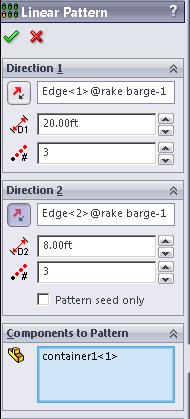
25 88. In the Assembly tab, click on Linear Component Pattern. 89. In the Components to Pattern field, click on container In Direction 1, select barge-1 barge Notice the grey arrow showing the direction of the pattern. If the direction is not correct, click on Reverse Direction. 92. In Direction 1, enter a Distance of 20ft and Number of Instances of 3.


26 93. In Direction 2, select barge-1 barge In Direction 2, enter a Distance of 8ft and Number of Instances of 3.

27 95. Click when you are done.

28 96. Perform the same mates and linear patterning to create a 2x3 row of container2 at the front of the rake barge. Your completed barge assembly should look like this 97. Click on the Evaluate tab and determine the Mass Properties of your completed barge assembly. Now open the MS Word or Notepad document that includes the Mass Properties of your rake barge part and compare the center of gravity to that of the assembly. What has occurred?

29 98. By changing the values of your distance mates in the assembly, you can move the containers forwards or backwards in the barge assembly. To do this, expand your Design Tree and find the mates for container Right click on the distance mate and select Edit Feature to change the value of the mate. This will allow you to move the containers forwards or backwards on the barge Design Challenge: Move the containers to arrive at a center of gravity as close as possible to the center of your rake barge. Save your work. Congratulations! You have completed Part V of this lesson.
Lab 3 Introduction to SolidWorks I Silas Bernardoni 10/9/2008
 1 Introduction This lab is designed to provide you with basic skills when using the 3D modeling program SolidWorks. You will learn how to build parts, assemblies and drawings. You will be given a physical
AEROPLANE. Create a New Folder in your chosen location called Aeroplane. The four parts that make up the project will be saved here.
 AEROPLANE Prerequisite Knowledge Previous knowledge of the following commands is required to complete this lesson. Sketching (Line, Rectangle, Arc, Add Relations, Dimensioning), Extrude, Assemblies and
Engineering Technology
 Engineering Technology Introduction to Parametric Modelling Engineering Technology 1 See Saw Exercise Part 1 Base Commands used New Part This lesson includes Sketching, Extruded Boss/Base, Hole Wizard,
Introduction to Circular Pattern Flower Pot
 Prerequisite Knowledge Previous knowledge of the sketching commands Line, Circle, Add Relations, Smart Dimension is required to complete this lesson. Previous examples of Revolved Boss/Base, Cut Extrude,
Lesson 10: Loft Features
 10 Goals of This Lesson Your students will be able to create the following part: profiles chisel This lesson plan corresponds to the Loft Features chapter of SolidWorks Getting Started. SolidWorks Student
g. Click once on the left vertical line of the rectangle.
 This drawing will require you to a model of a truck as a Solidworks Part. Please be sure to read the directions carefully before constructing the truck in Solidworks. Before submitting you will be required
Toothbrush Holder. A drawing of the sheet metal part will also be created.
 Prerequisite Knowledge Previous knowledge of the following commands is required to complete this lesson; Sketch (Line, Centerline, Circle, Add Relations, Smart Dimension,), Extrude Boss/Base, and Edit
Evaluation Chapter by CADArtifex
 The premium provider of learning products and solutions www.cadartifex.com EVALUATION CHAPTER 2 Drawing Sketches with SOLIDWORKS In this chapter: Invoking the Part Modeling Environment Invoking the Sketching
EXERCISE ONE: BEACH BUGGY.
 EXERCISE ONE: BEACH BUGGY. Prerequisite knowledge Students should have completed Exercises from the file: Introduction to Assemblies Concept Mates Focus of lesson Commands Used This lesson will focus on
Digital Camera Exercise
 Commands Used New Part This lesson includes Sketching, Extruded Boss/Base, Extruded Cut, Fillet, Chamfer and Text. Click File, New on the standard toolbar. Select Part from the New SolidWorks Document
Introduction to Revolve - A Glass
 Introduction to Revolve - A Glass Design & Communication Graphics 1 Object Analysis sheet Design & Communication Graphics 2 Prerequisite Knowledge Previous knowledge of the following commands are required
SolidWorks Tutorial 1. Axis
 SolidWorks Tutorial 1 Axis Axis This first exercise provides an introduction to SolidWorks software. First, we will design and draw a simple part: an axis with different diameters. You will learn how to
SolidWorks Part I - Basic Tools SDC. Includes. Parts, Assemblies and Drawings. Paul Tran CSWE, CSWI
 SolidWorks 2015 Part I - Basic Tools Includes CSWA Preparation Material Parts, Assemblies and Drawings Paul Tran CSWE, CSWI SDC PUBLICATIONS Better Textbooks. Lower Prices. www.sdcpublications.com Powered
DEPARTMENT OF MECHANICAL AND INDUSTRIAL ENGINEERING NORTHEASTERN UNIVERSITY
 DEPARTMENT OF MECHANICAL AND INDUSTRIAL ENGINEERING NORTHEASTERN UNIVERSITY CAPSULE PROGRAM Funded by NSF grant #0833636 Tutorial 02 3D Part Modeling SolidWorks 2010 Copyright 2010 Prof. Zeid 3D Part Modeling
Introduction to Parametric Modeling AEROPLANE. Design & Communication Graphics 1
 AEROPLANE Design & Communication Graphics 1 Object Analysis sheet Design & Communication Graphics 2 Aeroplane Assembly The part files for this assembly are saved in the folder titled Aeroplane. Open an
Engineering Design. with SolidWorks A Step-by-Step Project Based Approach Utilizing 3D Solid Modeling
 INSIDE: MultiMedia CD An audio/visual presentation of the tutorial projects Engineering Design with SolidWorks 2010 A Step-by-Step Project Based Approach Utilizing 3D Solid Modeling Introductory Level
SolidWorks Training. Introductory course for staff and students from the School of Physics and Astronomy
 SolidWorks Training Introductory course for staff and students from the School of Physics and Astronomy i) Introductory presentation SolidWorks Training ii) The SolidWorks GUI The SolidWorks Graphical
Engineering & Computer Graphics Workbook Using SOLIDWORKS
 Engineering & Computer Graphics Workbook Using SOLIDWORKS 2017 Ronald E. Barr Thomas J. Krueger Davor Juricic SDC PUBLICATIONS Better Textbooks. Lower Prices. www.sdcpublications.com Powered by TCPDF (www.tcpdf.org)
Solidworks Tutorial Pencil
 The following instructions will be used to help you create a Pencil using Solidworks. These instructions are ordered to make the process as simple as possible. Deviating from the order, or not following
for Solidworks TRAINING GUIDE LESSON-9-CAD
 for Solidworks TRAINING GUIDE LESSON-9-CAD Mastercam for SolidWorks Training Guide Objectives You will create the geometry for SolidWorks-Lesson-9 using SolidWorks 3D CAD software. You will be working
Introduction to Sheet Metal Features SolidWorks 2009
 SolidWorks 2009 Table of Contents Introduction to Sheet Metal Features Base Flange Method Magazine File.. 3 Envelopment & Development of Surfaces.. 14 Development of Transition Pieces.. 23 Conversion to
SolidWorks 2005 Tutorial. and MultiMedia CD. A Step-by-step Project Based Approach Utilizing 3D Solid Modeling
 INSIDE: MultiMedia CD An audio/visual presentation of the tutorial projects SolidWorks 2005 Tutorial and MultiMedia CD A Step-by-step Project Based Approach Utilizing 3D Solid Modeling David C. Planchard
Clock Exercise (Inserting Planes)
") Clock Exercise (Inserting Planes) Prerequisite Knowledge To complete this exercise you will need to be familiar with Sketching, Applying relations, Extrude Boss/ Base, Extrude cut, Applying Textures, Renaming
Clock Exercise (Inserting Planes) Prerequisite Knowledge To complete this exercise you will need to be familiar with Sketching, Applying relations, Extrude Boss/ Base, Extrude cut, Applying Textures, Renaming
Introducing SolidWorks
 Introducing SolidWorks SAAST Robotics 2008 SolidWorks Software Visually-based 3-D Mechanical design software Engineers and Designers use it to: Quickly sketch out ideas Experiment with features, dimensions
Introduction to 3D CAD with SolidWorks. Jianan Li
 Introduction to 3D CAD with SolidWorks Jianan Li Create a New Part The first time you launch SolidWorks, it asks you to set the default units and dimension standard. Make sure you have IPS and ANSI selected,
Foreword. If you have any questions about these tutorials, drop your mail to
 Foreword The main objective of these tutorials is to give you a kick start using Solidworks. The approach to write this tutorial is based on what is the most important knowledge you should know and what
Engineering & Computer Graphics Workbook Using SolidWorks 2014
 Engineering & Computer Graphics Workbook Using SolidWorks 2014 Ronald E. Barr Thomas J. Krueger Davor Juricic SDC PUBLICATIONS Better Textbooks. Lower Prices. www.sdcpublications.com Powered by TCPDF (www.tcpdf.org)
Computer Aided Design Module 2. Lesson Toblerone Bar
 Computer Aided Design Module 2 Lesson Toblerone Bar Lesson? Toblerone Bar New Commands used: Polygon, Add Relations, Smart Dimension, Extrude Boss/Base (Mid Plane), Fillet, Line, Extrude-Cut, Linear Pattern
SolidWorks 95 User s Guide
 SolidWorks 95 User s Guide Disclaimer: The following User Guide was extracted from SolidWorks 95 Help files and was not originally distributed in this format. All content 1995, SolidWorks Corporation Contents
Starting a 3D Modeling Part File
 1 How to Create a 3D Model and Corresponding 2D Drawing with Dimensions, GDT (Geometric Dimensioning and Tolerance) Symbols and Title Block in SolidWorks 2013-2014 By Edward Locke This tutorial will introduce
Beginner s Guide to SolidWorks Alejandro Reyes, MSME Certified SolidWorks Professional and Instructor SDC PUBLICATIONS
 Beginner s Guide to SolidWorks 2008 Alejandro Reyes, MSME Certified SolidWorks Professional and Instructor SDC PUBLICATIONS Schroff Development Corporation www.schroff.com www.schroff-europe.com Part Modeling
Advance Dimensioning and Base Feature Options
 Chapter 4 Advance Dimensioning and Base Feature Options Learning Objectives After completing this chapter you will be able to: Dimension the sketch using the autodimension sketch tool. Dimension the sketch
SolidWorks Tutorial 2 PICTURE HOLDER
 SolidWorks Tutorial 2 PICTURE HOLDER Preparatory Vocational Training and Advanced Vocational Training To be used with SolidWorks Educational Release 2008-2009 1995-2009, Dassault Systèmes SolidWorks Corp.
Modeling an Airframe Tutorial
 EAA SOLIDWORKS University p 1/11 Difficulty: Intermediate Time: 1 hour As an Intermediate Tutorial, it is assumed that you have completed the Quick Start Tutorial and know how to sketch in 2D and 3D. If
Veerapandian.K Mechanical Engg Vedharanyam A manual to mechanical designers How Solid works Works?
 Compiled by Veerapandian.K Mechanical Engg Vedharanyam-614 810 A manual to mechanical designers How Solid works Works? Solid works Overview Solid works main idea is user to create drawing directly in 3D
Shaft Hanger - SolidWorks
 ME-430 INTRODUCTION TO COMPUTER AIDED DESIGN Shaft Hanger - SolidWorks BY: DR. HERLI SURJANHATA ASSIGNMENT Submit TWO isometric views of the Shaft Hanger with your report, 1. Shaded view of the trimetric
SolidWorks Design & Technology
 SolidWorks Design & Technology Training Course at PHSG Ex 5. Lego man Working with part files 8mm At first glance the Lego man looks complicated but I hope you will see that if you approach a project one
Introduction to Autodesk Inventor for F1 in Schools (Australian Version)
") Introduction to Autodesk Inventor for F1 in Schools (Australian Version) F1 in Schools race car In this course you will be introduced to Autodesk Inventor, which is the centerpiece of Autodesk s Digital
Introduction to Autodesk Inventor for F1 in Schools (Australian Version) F1 in Schools race car In this course you will be introduced to Autodesk Inventor, which is the centerpiece of Autodesk s Digital
Revit Structure 2013 Basics
 Revit Structure 2013 Basics Framing and Documentation Elise Moss Supplemental Files SDC P U B L I C AT I O N S Schroff Development Corporation Better Textbooks. Lower Prices. www.sdcpublications.com Tutorial
Below are the desired outcomes and usage competencies based on the completion of Project 4.
 Engineering Design with SolidWorks Project 4 Below are the desired outcomes and usage competencies based on the completion of Project 4. Project Desired Outcomes: An understanding of the customer s requirements
Sash Clamp. Sash Clamp SW 2015 Design & Communication Graphics Page 1.
 Sash Clamp 1 Introduction: The Sash clamp consists of nine parts. In creating the clamp we will be looking at the improvements made by SolidWorks in linear patterns, adding threads and in assembling the
Hydro Hull. Chapter 21. Boat. A. Save as "HYDRO". Step 1. Open your HULL MID PLANE file (Chapter 2).
.") Chapter 21 Boat Hydro Hull A. Save as "HYDRO". Step 1. Open your HULL MID PLANE file (Chapter 2). Step 2. Click File Menu > Save As. Step 3. Key-in HYDRO for the filename and press ENTER. B. Delete Loft1,
Chapter 21 Boat Hydro Hull A. Save as "HYDRO". Step 1. Open your HULL MID PLANE file (Chapter 2). Step 2. Click File Menu > Save As. Step 3. Key-in HYDRO for the filename and press ENTER. B. Delete Loft1,
Chair. Bottom Rail. on the Command Manager. on the Weldments toolbar.
 Chapter 2 Chair Bottom Rail A. Weldments Toolbar. Step 1. Click File Menu > New, click Part and OK. Step 2. Right click Sketch on the Command Manager toolbar and select Weldments, Fig. 1. Step 3. Click
Revit Structure 2014 Basics
 Revit Structure 2014 Basics Framing and Documentation Elise Moss Authorized Author SDC P U B L I C AT I O N S Better Textbooks. Lower Prices. www.sdcpublications.com Powered by TCPDF (www.tcpdf.org) Visit
Revit Structure 2012 Basics:
 SUPPLEMENTAL FILES ON CD Revit Structure 2012 Basics: Framing and Documentation Elise Moss autodesk authorized publisher SDC PUBLICATIONS www.sdcpublications.com Schroff Development Corporation Structural
Lesson 6 2D Sketch Panel Tools
 Lesson 6 2D Sketch Panel Tools Inventor s Sketch Tool Bar contains tools for creating the basic geometry to create features and parts. On the surface, the Geometry tools look fairly standard: line, circle,
1. Open the Feature Modeling demo part file on the EEIC website. Ask student about which constraints needed to Fully Define.
 BLUE boxed notes are intended as aids to the lecturer RED boxed notes are comments that the lecturer could make Control + Click HERE to view enlarged IMAGE and Construction Strategy he following set of
Purlin Roof. Create a New Folder in your chosen location called Purlin Roof. The nine parts that make up the project will be saved here.
 Purlin Roof Prerequisite Knowledge Previous knowledge of the following commands is required to complete this lesson. Sketching (Line, Rectangle, Add Relations, Dimensioning), Inserting Planes, Extrude,
Bottom Rail. Chapter 2. Chair. A. Weldments Toolbar. Step 1. Click File Menu > New, click Part and OK. B. 3D Sketch.
 Chapter 2 Chair Bottom Rail A. Weldments Toolbar. Step 1. Click File Menu > New, click Part and OK. Step 2. Right click Sketch on the Command Manager toolbar and select Weldments, Fig. 1. Step 3. Click
Student + Instructor:
 BLUE boxed notes are intended as aids to the lecturer RED boxed notes are comments that the lecturer could make Show 01 Solid Modeling Intro slides quickly. SolidWorks Layout slides are on EEIC for reference
Creo Parametric Primer
 PTC Creo Parametric - Primer Student and Academic Editions 02 Helpful hints are enclosed in red brackets or round bubbles like this one! Creo Parametric Primer THIS VERSION OF THE CREO PRIMER HAS BEEN
Modeling Basic Mechanical Components #1 Tie-Wrap Clip
 Modeling Basic Mechanical Components #1 Tie-Wrap Clip This tutorial is about modeling simple and basic mechanical components with 3D Mechanical CAD programs, specifically one called Alibre Xpress, a freely
Creo Extrude Tutorial 2: Cutting and Adding Material
 Creo Extrude Tutorial 2: Cutting and Adding Material 1. Open Creo Parametric 2. File > Open > extrudeturial (From Creo Extrude Tutorial 1) 3. Cutting Material a. Click Extrude Icon > Select the following
CAD Tutorial. CAD Detail Windows. In this tutorial you ll learn about: CAD Detail Windows Exploding and Modifying a CAD Block
 CAD Tutorial In this tutorial you ll learn about: CAD Detail Windows Exploding and Modifying a CAD Block Creating a New CAD Block CAD Detail from View Creating a Plot Plan CAD Detail Windows CAD Details
Learning Guide. ASR Automated Systems Research Inc. # Douglas Crescent, Langley, BC. V3A 4B6. Fax:
 Learning Guide ASR Automated Systems Research Inc. #1 20461 Douglas Crescent, Langley, BC. V3A 4B6 Toll free: 1-800-818-2051 e-mail: support@asrsoft.com Fax: 604-539-1334 www.asrsoft.com Copyright 1991-2013
Working With Drawing Views-I
 Chapter 12 Working With Drawing Views-I Learning Objectives After completing this chapter you will be able to: Generate standard three views. Generate Named Views. Generate Relative Views. Generate Predefined
Introduction to Sweep - Allen Key part (A)
") Introduction to Sweep - Allen Key part (A) Prerequisite Knowledge Previous knowledge of the following commands is required to complete this lesson, sketching (line construction, dimensioning, polygon).
Introduction to Sweep - Allen Key part (A) Prerequisite Knowledge Previous knowledge of the following commands is required to complete this lesson, sketching (line construction, dimensioning, polygon).
On completion of this exercise you will have:
 Prerequisite Knowledge To complete this exercise you will need; to be familiar with the SolidWorks interface and the key commands. basic file management skills the ability to rotate views and select faces
Using Siemens NX 11 Software. The connecting rod
 Using Siemens NX 11 Software The connecting rod Based on a Catia tutorial written by Loïc Stefanski. At the end of this manual, you should obtain the following part: 1 Introduction. Start NX 11 and open
1. Creating geometry based on sketches 2. Using sketch lines as reference 3. Using sketches to drive changes in geometry
 4.1: Modeling 3D Modeling is a key process of getting your ideas from a concept to a read- for- manufacture state, making it core foundation of the product development process. In Fusion 360, there are
Creo Revolve Tutorial
 Creo Revolve Tutorial Setup 1. Open Creo Parametric Note: Refer back to the Creo Extrude Tutorial for references and screen shots of the Creo layout 2. Set Working Directory a. From the Model Tree navigate
SolidWorks Navigation
 SolidWorks Basics SolidWorks Navigation Command Bar Feature Tree Model Window Simple Box Select the Front plane Create a new sketch Create a Center Rectangle from the origin Smart Dimension the length
Introduction to SolidWorks Introduction to SolidWorks
 Introduction to SolidWorks Introduction to SolidWorks SolidWorks is a powerful 3D modeling program. The models it produces can be used in a number of ways to simulate the behaviour of a real part or assembly
SolidWorks Reference Geometry
 SolidWorks Reference Geometry IDeATe Laser Micro Part 2 Dave Touretzky and Susan Finger 1. Symmetry and Reference Geometry Today, you ll make this part bear-like face and then cut it on the laser cutter:
Model House Exercise-( Extrude)
") -( Extrude) Prerequisite knowledge Focus of the lesson Commands Used This lesson requires an understanding of using the sketch commands including Inserting a new sketch Adding sketch geometry Understanding
-( Extrude) Prerequisite knowledge Focus of the lesson Commands Used This lesson requires an understanding of using the sketch commands including Inserting a new sketch Adding sketch geometry Understanding
Siemens NX11 tutorials. The angled part
 Siemens NX11 tutorials The angled part Adaptation to NX 11 from notes from a seminar Drive-to-trial organized by IBM and GDTech. This tutorial will help you design the mechanical presented in the figure
Tech-World Manufacturing. Design. Level two. CELL Guide. Edition E0
 Tech-World Manufacturing Design Level two Edition 5 37186-E0 FIFTH EDITION First Printing, February 2011 Copyright 2005, 2006, 2007, 2008, 2009, 2010, 2011 Lab-Volt Systems, Inc. All rights reserved.
Solidworks tutorial. 3d sketch project. A u t h o r : M. G h a s e m i. C o n t a c t u s : i n f s o l i d w o r k s a d v i s o r.
 Solidworks tutorial 3d sketch project A u t h o r : M. G h a s e m i C o n t a c t u s : i n f o @ s o l i d w o r k s a d v i s o r. c o m we will create this frame during the tutorial : In this tutorial
digitization station DIGITAL SCRAPBOOKING 120 West 14th Street
 digitization station DIGITAL SCRAPBOOKING 120 West 14th Street www.nvcl.ca techconnect@cnv.org DIGITAL SCRAPBOOKING With MyMemories Suite 6 The MyMemories Digital Scrapbooking software allows you to create
Quick Start for Autodesk Inventor
 Quick Start for Autodesk Inventor Autodesk Inventor Professional is a 3D mechanical design tool with powerful solid modeling capabilities and an intuitive interface. In this lesson, you use a typical workflow
Feature-Based Modeling and Optional Advanced Modeling. ENGR 1182 SolidWorks 05
 Feature-Based Modeling and Optional Advanced Modeling ENGR 1182 SolidWorks 05 Today s Objectives Feature-Based Modeling (comprised of 2 sections as shown below) 1. Breaking it down into features Creating
Table of Contents. Lesson 1 Getting Started
 NX Lesson 1 Getting Started Pre-reqs/Technical Skills Basic computer use Expectations Read lesson material Implement steps in software while reading through lesson material Complete quiz on Blackboard
Drawing Layouts Paper space & Model Space
 Drawing Layouts Paper space & Model Space Users of Bricscad will have seen the tabs at the bottom left of the drawings area labelled: Model, Layout1, Layout2 but may not know how to use them or what they
TOY TRUCK. Figure 1. Orthographic projections of project.
 TOY TRUCK Prepared by: Harry Hawkins The following project is of a small, wooden toy truck. This exercise will provide you with the procedure for constructing the various parts of the design then assembling
Chapter 2. Modifying, Extruding and Revolving the Sketches. Learning Objectives. Commands Covered AMMODDIM AMEXTRUDE AMREVOLVE
 Chapter 2 Modifying, Extruding and Revolving the Sketches Learning Objectives After completing this chapter, you will be able to: Modify the desired sketch using the AMMODDIM command. Extrude the desired
Introduction to 3D Printing. Activity 1: Design a keychain using computer-aided design software
 Introduction to 3D Printing Activity 1: Design a keychain using computer-aided design software 1 In this activity we ll design a keychain name tag and learn the fundamentals of computer-aided design, the
SDC. SolidWorks Tutorial 2001Plus. A Competency Project Based Approach Utilizing 3D Solid Modeling. David C. Planchard & Marie P.
 2001Plus A Competency Project Based Approach Utilizing 3D Solid Modeling David C. Planchard & Marie P. Planchard SDC PUBLICATIONS www.schroff.com www.schroff-europe.com Project 2 Below are the desired
House Design Tutorial
 House Design Tutorial This House Design Tutorial shows you how to get started on a design project. The tutorials that follow continue with the same plan. When you are finished, you will have created a
Lesson 6: Drawing Basics
 6 Lesson 6: Drawing Basics Goals of This Lesson Understand basic drawing concepts. Create detailed drawings of parts and assemblies:. Before Beginning This Lesson Create Tutor1 and Tutor2 parts and the
Spatula. Spatula SW 2015 Design & Communication Graphics Page 1
 Spatula Introduction: The model shown in the picture is made of three parts, - the base, the washer and the handle. The base requires the use of Spline and Style Spline command, Slot command and Mirror
E11: Autonomous Vehicles. Lab 2: 3D CAD and Printing
 E11: Autonomous Vehicles Lab 2: 3D CAD and Printing The goal of this lab is to create a robot chassis in SolidWorks that can be printed on HMC s 3D printer. When you are done, the chassis should look like
Copyrighted. Material. Copyrighted. Material. Copyrighted. Material. Copyrighted. Material
 ENGINEERING & COMPUTER GRAPHICS WORKBOOK Using SolidWorks 2005 Ronald E. Barr Thomas J. Krueger Theodore A. Aanstoos Davor Juricic SDC PUBLICATIONS Schroff Development Corporation www.schroff.com www.schroff-europe.com
Copyrighted. Material. Copyrighted. Material. Copyrighted. Material. Copyrighted. Material
 ENGINEERING & COMPUTER GRAPHICS WORKBOOK Using SolidWorks 2008 Ronald E. Barr Thomas J. Krueger Theodore A. Aanstoos Davor Juricic SDC PUBLICATIONS Schroff Development Corporation www.schroff.com Better
Applied Precast Concrete Detailing
 Applied Precast Concrete Detailing Tekla Structures 11.0 August 30, 2005 Copyright 2005 Tekla Corporation Copyright 2005 Tekla Corporation Applied Precast Concrete Detailing i Copyright 2005 Tekla Corporation
Engineering Design with SolidWorks A Step-by-Step Project Based Approach Utilizing 3D Solid Modeling. David C. Planchard & Marie P.
 Engineering Design with SolidWorks 2003 A Step-by-Step Project Based Approach Utilizing 3D Solid Modeling David C. Planchard & Marie P. Planchard SDC PUBLICATIONS www.schroff.com www.schroff-europe.com
Alibre Design Tutorial: Loft, Extrude, & Revolve Cut Loft-Tube-1
 Alibre Design Tutorial: Loft, Extrude, & Revolve Cut Loft-Tube-1 Part Tutorial Exercise 5: Loft-Tube-1 [Complete] In this Exercise, We will set System Parameters first, then part options. Then, in sketch
INTRODUCING SOLIDWORKS
 INTRODUCING SOLIDWORKS Contents Legal Notices...6 Introduction...9 The SOLIDWORKS Software...9 Intended Audience...9 System Requirements...9 Document Structure...9 Conventions Used in this Document...10
10/14/2010. Chevy Malibu. Vehicle Design with Solidworks. Start SolidWorks Create a New SolidWorks Document. Miles, Rowardo B
 Chevy Malibu Vehicle Design with Solidworks Start SolidWorks Create a New SolidWorks Document Miles, Rowardo B 1 Click: Part and then OK Now you are ready to make a Part. 2 Right Toolbar: Document Properties:
Creo Parametric Primer
 Creo Parametric Primer Creo Parametric Primer Education Editions C1-SE-L1-004-1.0 Written by Tim Brotherhood and Adam Haas Conditions of use Acknowledgements Feedback tbrotherhood@ptc.com Product code
COMPUTING CURRICULUM TOOLKIT
 COMPUTING CURRICULUM TOOLKIT Pong Tutorial Beginners Guide to Fusion 2.5 Learn the basics of Logic and Loops Use Graphics Library to add existing Objects to a game Add Scores and Lives to a game Use Collisions
SMALL OFFICE TUTORIAL
 SMALL OFFICE TUTORIAL in this lesson you will get a down and dirty overview of the functionality of Revit Architecture. The very basics of creating walls, doors, windows, roofs, annotations and dimensioning.
< Then click on this icon on the vertical tool bar that pops up on the left side.
 Pipe Cavity Tutorial Introduction The CADMAX Solid Master Tutorial is a great way to learn about the benefits of feature-based parametric solid modeling with CADMAX. We have assembled several typical parts
Module 1G: Creating a Circle-Based Cylindrical Sheet-metal Lateral Piece with an Overlaying Lateral Edge Seam And Dove-Tail Seams on the Top Edge
 Inventor (10) Module 1G: 1G- 1 Module 1G: Creating a Circle-Based Cylindrical Sheet-metal Lateral Piece with an Overlaying Lateral Edge Seam And Dove-Tail Seams on the Top Edge In Module 1A, we have explored
Getting Started Guide
 SOLIDWORKS Getting Started Guide SOLIDWORKS Electrical FIRST Robotics Edition Alexander Ouellet 1/2/2015 Table of Contents INTRODUCTION... 1 What is SOLIDWORKS Electrical?... Error! Bookmark not defined.
Engineering Design with
 Engineering Design with SOLIDWORKS 2016 and Video Instruction A Step-by-Step Project Based Approach Utilizing 3D Solid Modeling David C. Planchard, CSWP, SOLIDWORKS Accredited Educator SDC PUBLICATIONS
From the above fig. After sketching the path and profile select the sweep command First select the profile from property manager tree And then select
 Chapter 5 In sweep command there is a) Two sketch profiles b) Two path c) One sketch profile and one path The sweep profile is used to create threads springs circular things and difficult geometry. For
Drawing and Assembling
 Youth Explore Trades Skills Description In this activity the six sides of a die will be drawn and then assembled together. The intent is to understand how constraints are used to lock individual parts
House Design Tutorial
 Chapter 2: House Design Tutorial This House Design Tutorial shows you how to get started on a design project. The tutorials that follow continue with the same plan. When you are finished, you will have