AUTO CAD CIVIL ENGINEERING LABORATORY MANUAL DEPARTMENT OF
|
|
|
- Myles McDonald
- 5 years ago
- Views:
Transcription
1 AUTO CAD LABORATORY MANUAL DEPARTMENT OF CIVIL ENGINEERING
2 MANDATORY INSTRUCTIONS 1. Students should report to the labs concerned as per the timetable. 2. Record should be updated from time to time and the previous experiment must be signed by the faculty in charge concerned before attending the lab. 3. Students who turn up late to the labs will in no case be permitted to perform the experiment scheduled for the day. 4. After completion of the experiment, certification of the staff in-charge concerned in the observation book is necessary. 5. Students should bring a notebook of about 100 pages and should enter the readings/observations/results into the notebook while performing the experiment. 6. The record of observations along with the detailed experimental procedure of the experiment performed in the immediate previous session should be submitted and certified by the staff member in-charge. 7. Not more than FIVE students in a group are permitted to perform the experiment on a set up. 8. The group-wise division made in the beginning should be adhered to, and no mix up of student among different groups will be permitted later. 9. The components required pertaining to the experiment should be collected from Lab-in-charge after duly filling in the requisition form. 10. When the experiment is completed, students should disconnect the setup made by them, and should return all the components/instruments taken for the purpose. 11. Any damage of the equipment or burnout of components will be viewed seriously either by putting penalty or by dismissing the total group of students from the lab for the semester/year. 12. Students should be present in the labs for the total scheduled duration. 13. Students are expected to prepare thoroughly to perform the experiment before coming to Laboratory. 14. Procedure sheets/data sheets provided to the students groups should be maintained
3 neatly and are to be returned after the experiment. 15. DRESS CODE: 1. Boys - Formal dress with tuck in and shoes. 2. Girls - Formal dress (salwarkameez). 3. Wearing of jeans is strictly prohibited
4 COMPUTER AIDEDRAFTING OF BUILDINGS S.NO LIST OF EXPERIMENTS PAGE NO: 1 Introduction to computer aided drafting 2 Software for CAD- Introduction to different software s 3 Practice exercises on CAD software 4 Drawing of plans of buildings using software a) Single storeyed b) Multi storeyed 5 Developing sections and elevations for a) Single storeyed b) Multi storeyed 6 Detailing of building components like doors, windows, roof trusses etc. using CAD software s 7 Exercises on development of working of buildings
5 Experiment No. 1 INTRODUCTION TO COMPUTER AIDED DRAFTING Computer Aided Drafting is a process of preparing a drawing of an object on the screen of a computer. There are various types of drawings in different fields of engineering and sciences. In the fields of mechanical or aeronautical engineering, the drawings of machine components and the layouts of them are prepared. In the field of civil engineering, plans and layouts of the buildings are prepared. In the field of electrical engineering, the layouts of power distribution system are prepared. In all fields of engineering use of computer is made for drawing and drafting. The use of CAD process provides enhanced graphics capabilities which allows any designer to Conceptualize his ideas Modify the design very easily Perform animation Make design calculations Use colors, fonts and other aesthetic features. 1.1 REASONS FOR IMPLEMENTING A CAD SYSTEM 1. Increases the productivity of the designer: CAD improves the productivity of the designer to visualize the product and its component, parts and reduces the time required in synthesizing, analyzing and documenting the design 2. Improves the quality of the design: CAD system improves the quality of the design. A CAD system permits a more detailed engineering analysis and a larger number of design alternatives can be investigated. The design errors are also reduced because of the greater accuracy provided by the system 3. Improves communication: It improves the communication in design. The use of a CAD system provides better engineering drawings, more standardization in the drawing, and better documentation of the design, few drawing errors and legibility. 4. Create data base for manufacturing: In the process of creating the documentation for these products, much of the required data base to manufacture the products is also created. 5. Improves the efficiency of the design: It improves the efficiency of the design process and the wastage at the design stage can be reduced
6 6. APPLICATION OF CAD: There are various processes which can be performed by use of computer in the drafting process. 1. Automated drafting: This involves the creation of hard copy engineering drawings directly from CAD data base. Drafting also includes features like automatic dimensioning, generation of cross hatched areas, scaling of the drawing and the capability to develop sectional views and enlarged views in detail. It has ability to perform transformations of images and prepare 3D drawings like isometric views, perspective views etc., 2. Geometric modeling: concerned with the computer compatible mathematical description of the geometry of an object. The mathematical description allows the image of an object to be displayed and manipulated on a graphics terminal through signals from the CPU of the CAD system. The software that provides geometric modeling capabilities must be designed for efficient use both by computer and the human designer. 1.2 BENEFITS OF CAD: The implementation of the CAD system provides variety of benefits to the industries in design and production as given below: 1. Improved productivity in drafting 2. Shorter preparation time for drawing 3. Reduced man power requirement 4. Customer modifications in drawing are easier 5. More efficient operation in drafting 6. Low wastage in drafting 7. Minimized transcription errors in drawing 8. Improved accuracy of drawing 9. Assistance in preparation of documentation 10. Better designs can be evolved 11. Revisions are possible 12. Colors can be used to customize the product 13. Production of orthographic projections with dimensions and tolerances 14. Hatching of all sections with different filling patterns
7 1.3 LIMITATIONS OF CAD bit word computer is necessary because of large amount of computer memory and time 2. The size of the software package is large 3. Skill and judgment are required to prepare the drawing 4. Large investment. 1.4 Pre-lab questions: 1. Full form of AUTO CAD 2. What are the benefits of auto cad? 3. What are the reasons for implementing of auto cad? 1.5 Post lab questions: 1. Briefly explain application of auto cad? 2. What are the benefits of auto cad in civil engineering point of view? 3. What are the limitations of auto cad?
8 Experiment No. 2 SOFTWARE FOR CAD- INTRODUCTION TO DIFFERENT SOFTWARE S CAD SOFTWARES The software is an interpreter or translator which allows the user to perform specific type of application or job related to CAD. The following software s are available for drafting 1. AUTOCAD 7. MSc. NASTRAN 2. Pro E 8. IDEAS 3. CATIA 9. SOLID WORKS 4. MS OFFICE 10. HYPERMESH 5. PAINT 11. FLUENT GAMBIT 6. ANSYS The above software s are used depending upon their application. AUTO CAD Auto CAD package is suitable for accurate and perfect drawings of engineering designs. The drawing of machine parts, isometric views and assembly drawings are possible in AutoCAD. The package is suitable for 2D and 3D drawings. 2.1 STARTING WITH AUTO CAD CAD uses four basic elements for preparation of any drawing: 1. Line 3. Text 2. Curves 4. Filling point. Computer Aided Drafting is done by the operator by placing the mouse pointer by placing the mouse pointer at the desired location and then executing the command to draw the graphic elements using different methods. Advanced computer aided drafting packages utilize four areas on the screen. 1. Drawing Area 2. Command Area
9 3. Menu Area 4. Tool Boxes. 2.2 Layout and Sketching The package provides various facilities for layout, sketching and borders for preparing a drawing. It provides facilities for display co-ordinates and measurement units. a. Units: The format for display co ordinates and measurement can be selected according to the requirement. Several measurement styles are available in ACAD. The main methods are engineering and architectural, having specific base unit assigned to them. i. Decimal: select to enter and display measurements in decimal notation ii. iii. iv. Engineering: Display measurements in feet and decimal inches. Architectural: Display measurements in feet, inches and fractional inches Fractional: Display measurements in mixed numbers notation v. Scientific: Display measurements in scientific notation. The precision that is specified controls the number of decimal places or fractional size to which we want linear measurements displayed. b. Angles: Select the format in which we want to enter and display angles. i. Decimal Degrees: Display partial degrees as decimals ii. iii. iv. Deg/Min/Sec: Display partial degrees as minutes and seconds. Grades: Display Angles as grades Radians: Display angles as radians. v. Surveyor: Displays angles in surveyor units. c. Angle measure: Select the direction of the zero angle for the entry of angles: i. East: Select to specify the compass direction east as the zero angles. ii. iii. iv. North: Select to specify the compass direction north as the zero angles. West: Select to specify the compass direction west as the zero angles. South: Select to specify the compass direction south as the zero angles. v. Other: Select to specify a direction different from the points of the compass as the zero angles. d. Area: Enter the approximate width and length which is planned to draw in full scale units. This limits the area of the drawing covered by grid dots when the grid is turned on. It also adjusts several default settings, such as text height, line type scaling and
10 snap distance to convenient values. It is possible to adjust these settings. e. Title block: Select the description of an ACAD drawing file of a title block to insert as a symbol in the new drawing. It can add or remove drawing files of title blocks from the list with the Add or Remove buttons f. Layout: Paper space is often used to create complex multiple view drawings. There are three types of paper spaces: 1. Work on the drawing while viewing the layout. 2. Work on the drawing without the layout visible 3. Work on the layout of the drawing. The following procedure is used for this purpose 1. From the File menu or from the standard tool bar, choose New 2. In the startup dialog box, choose Use a wizard, and select Advanced wizard 3. Choose OK 4. In the Advanced Setup Dialog box, select Title Block. 5. Select Title Block Description and Title Block file Name from the lists and then choose Add. 6. In the Select Title Block File dialog box, Select a title block, then choose open 7. In the Advanced Setup dialog box, a sample of that title is displayed. 8. Choose Done. 2.3 DRAWING ENVIRONMENT ACAD provides two drawing environments for creating and laying out the drawing. i. Model Space ii. Paper Space. ACAD allows creating drawing, called a model, in full scale in an area known as model space without regard to the final layout or size when the drawing is plotted on the paper. In the space opened for the first time, it is possible to create floating viewports to contain different views of the model. In the paper space, floating viewports are treated as objects which can be moved and resized in order to create a suitable layout. LIMITS This sets and controls the drawing boundaries.
11 At the command prompt, enter limits ON/OFF/<LOWER LEFT CORNER> <current>: Specify a point, enter on or off, or press enter. LTSCALE This sets the line type scale factor. Use LTSCALE to change the relative length of the dash dot line types per drawing unit At the Command prompt, enter ltscale New scale factor <current>: Enter a positive real value or press enter Changing the line type scale factor causes the drawing to regenerate. MEASURE This places point objects or blocks at measured intervals on an object. At the command prompt, enter measure Select object to measure: Use an object selection method <segment length> / Block: Specify a distance. PAN This moves the drawing display in the current viewport. At the command prompt, enter pan Displacement: Specify a point (1) The point which specify indicates the amount to move the drawing or the location of the drawing to be moved. Second point: Press or specify a point (2) If pressed, ACAD moves the drawing by the amount which is specified in the
12 Displacement prompt. If we specify a point, ACAD moves the location of the drawing to that point. 2.4 ELEMENTS OF DRAWING DRAW COMMANDS LINE: A line is specified by giving its two end points or first point and the distance of line along with its angle of inclination. A line can be drawn by using two commands. Command: line Specify first point: Specify a point (1) Specify next point or [Undo]: Specify a point (2) The second point can be indicated Where d is the distance of line and a is the angle of inclination in degrees. PLINE: This is a poly line which allows continuous segment of the line and it is drawn similar to the line command. The polyline allows changing the thickness of the line according to the requirement. From the Draw tool bar choose the Polyline flyout. Draw pull down menu: Polyline At the command prompt, enter pline Syntax Specify start point: Specify a point (1) Current line-width is <current> Specify next point or [Arc/Close/Half width/length/undo/width]: Specify a point (2) or enter an option

13 LINETYPE Creates, loads, and sets line types. The LINETYPE command defines line characteristics consisting of dashes, dots, and spaces. Format menu: Line type or Command line: line type 1. CURVES Following are the various types of i. Circle ii. Ellipse iii. Arc iv. Regular or any other type. i. Circle: The circle can be drawn by using two types of commands a. Circle b. Donut a) CIRCLE: This command draws the circle by using four
14 methods: Center point and radius Two point circle Three point circle Tangent circle At the command prompt, enter circle Specify center point for circle or [3P (Three Points)/2P (Two Points)/Ttr]: Specify a point or enter an option b) DONUT: This draws filled circles and rings. Donuts are constructed of a closed polyline composed of wide arc segments. At the command prompt, enter donut Specify inside diameter of donut <current>: Specify a distance or press ENTER If you specify an inside diameter of 0, the donut is a filled circle. Specify outside diameter of donut <current>: Specify a distance or press ENTER Specify center of donut or <exit>: Specify a point (1) or press ENTER to end the command ii. ELLIPSE: It is a curve having major and minor axis with a center. The ellipse can be prepared by four methods. ELLIPSE Creates an ellipse or an elliptic arc. Axis end point: Defines the first axis by two specified endpoints. The angle of the first axis determines the angle of the ellipse. The first axis can define either the major or the minor axis of the ellipse. Arc: Creates an elliptical arc. The angle of the first axis determines the angle of the elliptical arc. The first axis can define either the major or the minor axis of the elliptical arc. Center: Creates the ellipse by a specified center point.
15 Isocircle: Creates an isometric circle in the current isometric drawing plane. At the command prompt, enter ellipse iii. Arc: The arc is a curve specified by center and radius as well as the start angle and end angle. There are seven method used for drawing an arc. 1. Three point method 2. Start point-center point end point 3. Start point-center point-length of chord 4. Start point-end point angle of inclusion 5. Start point-end point-direction 6. Start point-center point-angle of inclusion 7. Start point-end point-radius These methods can be used by executing the arc command ARC: creates an arc. At the command prompt, enter arc Center/<start point>: specify a point, enter c, or press enter Polyarc: the second method of the drawing the arc is poly arc by use of pline command. This command allows drawing of filled arc of any width.it also allows for drawing of a regular or irregular curve. 2. Drawing of Rectangle: A rectangle can be drawn by LINE command or by Rectangle command. The PLINE command also allows for drawing of hollow or filled rectangle.a SOLID command is also used for drawing of filled rectangles.
16 1. RECTANGLES: draws a rectangular polyline At the command prompt, enter rectangle First corner: specify point (1) Other corner: specify point (2) 2. SOLID: creates solid filled polygons.solids are filled only when fill system variable is set to on view is set to plan. At the command prompt, enter solid First corner: specify point (1) Other corner: specify point (2) The first two points define one edge of the polygon. Third point: specify a point (3) diagonally opposite the second Forth point: specify a point (4) or press enter 3. DRAWING OF POLYGON Creates an equilateral closed polyline.a polygon is a polyline object. AUTOCAD draws polyline with zero width and no tangent information. At the command prompt enter polygon Number of sides <current>: enter a value between 3 and 1024 or press enter Edge/<center of polygon>: specify a point (1) or enter. 4. POINT Creates a point object.points can act as nodes to which you can snap objects.you can specify a full 3D location for a point. At the command prompt, enter point Point: specify a point 5. ERASING OF OBJECT:
17 The object can be removed or erased by use of erase command ERASE This removes object from drawing At the command prompt, enter erase Select objects: use an object selection method. 6. COLOURING OF OBJECT: The object can be drawn with any variety of colour which ranges from 0 to 256. The setting of colour can be done by color command COLOR Sets the colour for new objects. At the command prompt, enter color <current>: enter a value (1-255), color name, by block, or by layer 7. FILLING OF OBJECT: the object can be filled with different colors and patterns by use of hatch command This command allows selection of various patterns, scale of pattern and angle of pattern. HATCH This fills an area with a pattern. HATCH fills the specified hatch boundary with non-associative hatch A non associative hatch is not updated when its boundaries are modified.a hatch boundary consists of an object or objects that completely enclose an area At the command prompt, enter hatch Pattern (? Or name/ U, style) <current>: enter a predefined pattern name, enter u, enter? Or press enter. 8. SCALING OF DRAWING: zoom command displays the object at a specified scale factor. the value entered is relative to the limits of the drawing.for example,entering 2 doubles the apparent display size of any objects from what it would be if it were zoomed to the limits of the drawing
18 If you enter a value followed by xp, auto CAD specifies the scale relative to paper scale unit s.for example, entering 0.5xp displays model space at half the scale of paper space unit s.the following illustration shows a number of viewports arranged in paper space. the view in each view port is scaled relative to paper space.the first view is scaled 1=1 relative to paper space (1xp),the second is scaled 0.5=1 relative to paper space (0.5xp),and so on. ZOOM This increases or decreases the apparent size of objects in the current view port At the command prompt, enter zoom All/center/dynamic/extents/left/previous/vmax/window/<scale(x/xp)>: enter an option or value, specify a point, or press enter. 9. TEXT: The text in software is indicated by font s.the fonts define the shapes of the text characters that make up each character set. In AUTOCAD, you can use true type fonts in addition to AUTOCAD s own compiled shape (SHX) fonts. A font is indicated by various parameters like i. Style :these are four types: normal,bold,italic,underline ii. Size: this is the size of characters iii. Colour: there are facilities to colour the characters selecting layer. iv. Type: different types of fonts may be used: Mono text: COMPUTER AIDED DESIGN Romans: COMPUTER AIDED DESIGN Romand: COMPUTER AIDED DESIGN Dtext: This displays text on the screen as it is entered.autocad can create text with a variety of character patterns, or fonts. These fonts can be stretched, compressed, oblique, mirrored, or aligned in a vertical column by applying a style to the font.text can be rotated, justified, and made any size.
19 At the command prompt, enter text Justify/style/<start point>: specify a point or enter an option TEXT: This creates a single line of text.autocad can create text with a variety of character patterns, or fonts. These fonts can be stretched, compressed, oblique, mirrored, or aligned in a vertical column by applying a style to the font. At the command prompt, enter text Justify/style/<start point>: specify a point or enter an option QTEXT: This controls the display and plotting of text and attribute of objects. At the command prompt, enter text ON/OFF <current>: enter on or off, or press enter 10. TRANSFORMATIONS: These are the modifications in the drawn objects. There are different types of transformations used 1. MOVE: This allows to move or displace objects a specified distance in a specified direction At the command prompt, enter move Select objects: use an object selection method Base point or displacement: specify a base point (1) Second point of displacement: specify a point (2) or press enter 2. COPY: This is used for producing a duplicate copy of the drawing. At the command prompt, enter copy Select objects: use an object selection method <Base point or displacement >/multiple: specify a base
20 3. ROTATE: It moves objects about a base point At the command prompt, enter rotate Select objects: use an object selection method <Rotate angle >/reference: specify an angle or enter r 4. STRETCH: This moves or stretches objects.autocad stretches lines, arcs, elliptical arcs, splines, rays and polyline segments that cross the selection window. At the command prompt, enter stretch Select objects: use the CPOLYGON or cross object selection method (1,2) Base point or displacement: specify a point (3) or press Second point of displacement: specify a point ($) or press 5. EXTEND: This extends an object to meet another object. Objects that can be extended include arcs, elliptical arcs, lines, open 2D, and 3Dpolylines and rays. At command prompt, enter extend Select boundary edges (projmode=ucs, edge mode=no extend) Select objects: use an object selection method 6. SCALE: This enlarges or reduces selected objects equally in X and Y directions At the command prompt, enter scale Select objects: use an object selection method Base point: specify a point (1) <Scale factor>/reference: specify a scale or enter r
21 7. TRACE: This creates solid lines. From the miscellaneous tool bar choose At the command prompt, enter trace Trace width<current>: specify a distance, enter a value, or press enter From point: specify point (1) To point: specify a point (2) To point: specify a point (3) or press to end the command 8. EXTRUDE: This creates unique solid primitives by extruding existing two-dimensional objects extrudes also creates solids by extruding two-dimensional objects along a specified path.we can extrude multiple objects with extrude At the command prompt enter, extrude Select objects: use an object selection method Path/<height of extrusion>: specify a distance or enter p 9. MIRROR: This is used to producing mirror image of the object At the command prompt enter, mirror Select objects: use an object selection method First point of the mirror line: specify a point (1) Second point: specify a point (2) 10. OFFSET: This creates concentric circles,parallel lines and parallel curves, offset creates a creates a new object at a specified distance from an existing object or through a specified point At the command prompt enter, offset Offset distance: specify a distance, enter t or press enter
22 11. ARRAY: This creates multiple copies of objects in pattern. Each object in an array can be manipulated independently At the command prompt enter, array Rectangular or polar array<current>: enter an option or press enter specify a point 12. CUTTING OF OBJECTS The drawn objects can be cut or trimmed by using following commands 1. TRIM: Trims objects at a cutting object defined by other objects. Objects that can be trimmed include arcs,circles, elliptical arcs, lines, open 2D and 3Dpolylines,rays and splines At the command prompt, enter trim Select cutting edges: Select objects: use object selection method <Select object to trim>/project/edge/undo: select an object, enter an option, or press enter 2. BREAK: This erases an object or splits the object in to two parts From the modify toolbar select break flyout At the command prompt, enter break Select objects: use an object selection method First point of the mirror line: specify a point (1) on an object Enter second point: specify the second break point (2) or enter F
23 13. DIMENSIONING IN DRAWINGS: The dimensions are inserted in the drawing by use of DIM command. There are various types of dimensions used in AutoCAD. 1. Linear dimensions: Horizontal- this allows horizontal dimensions Vertical- this allows vertical dimensions Aligned- this allows inclined dimensions Rotated- this allows inclined dimensions 2. Angular dimensions: This allows angular dimensioning of objects 3. Radial dimensions: This allows radial dimensioning of arc or circle 4. Diametric dimensions: This allows diametrical dimensions of the circle For dimensioning of objects, the first point and second point has to be specified. The dimension text must be written and then the position of dimension must be specified At the command prompt, enter dim Dim: Enter a dimensioning mode command 14. AREA: This allows calculation of the area and perimeter of objects or of defined areas From the object properties toolbar, choose the inquiry flyout, then At the command prompt, enter area <First point>/object/add/subtract: specify a point or enter option
24 15. FILLET Rounds and fillets the edges of the object At the command prompt enter fillet Polyline / Radius / Trim / <Select first object>: use an object selection method or enter an option Select first object Select second object: use an object selection method Enter radius <current>: specify a distance or press Chain / Radius <Select edge>: Select edges or enter c or r their intersection 16. CO-ORDINATE SYSTEM The co- ordinate system can be modified in the AutoCAD. There are two types of co-ordinate systems used. The WCS (World co- ordinate system) is a universal system in which its origin is at the fixed position. The UCS (User co- ordinate system) is a system in which user can fix his origin at any point. 1. UCS : This manages user co- ordinate systems At the command prompt enter UCS 17. UNION: This measures the distance and angle between two points. At the command prompt, enter union Select object: Use an object selection method
25 18. DIST: This measures the distance and the angle between two points. At the command prompt area enter dist First point: Specify a point (1) Second point: Specify a point (2) Distance = calculated distance Angle in XY plane = angle from XY plane = angle Delta X = change in X Delta Y = change in Y Delta Z = change in Z. 19. REGENERATION OF DRAWING: ACAD provides a facility of regenerating a drawing to clear the cross points or marks on the screen. REDRAW REGEN REGENALL 21. TOLERANCE REGENAUTO This creates geometric tolerances. Geometric tolerances define the maximum allowable variations of form or profile, orientation, location and runout from the exact geometry in a drawing. They specify the required accuracy for proper function and fit the objects drawn in AutoCAD
26 22. SKETCH This creates a series of free hand line segments. From the miscellaneous toolbar, choose At the command prompt enter sketch Follow the prompting 2.5 3D FUNCTIONS 1. BOX This creates a three dimensional solid box. At command prompt enter box Center/<corner of the box><0,0,0> : Specify a point (1), enter c, or press enter Corner of a box Specifying a point or pressing defines the first corner of the box. Cube/length /<other corner>: specify a point (2) or enter an option center 2. CONE Creates the box by a specified center point This creates a 3D solid cone. A cone is solid primitive with a circular or elliptical based tapering symmetrically to a point perpendicular to its base. At the command prompt enter cone Elliptical /<center point> <0,0,0>: specify a point, enter e or press enter 3. CYLINDER This creates a 3D solid cylinder. A cylinder is solid primitive with a circular or elliptical based to a point perpendicular to its base without a taper. At the command prompt enter cylinder Elliptical /<center point> <0,0,0> : specify a point, enter e or press enter
27 4. SPHERE This creates a 3D solid sphere. A sphere is positioned so that its central axis is parallel to the Z- axis of the current UCS. Latitudinal lines are parallel to the XY plane. At the command prompt enter sphere center of the sphere <0,0,0> : specify a point, enter e or press enter 5. WEDGE This creates a three dimensional solid with a sloped face tapering along X axis. At the command prompt enter wedge Center <corner of the wedge> <0,0,0> : specify a point, enter e or press enter Follow the prompting 6. ELEV This sets an elevation and extrusion thickness of new objects. The current elevation is the Z value that is used whenever a 3D point is expected but only X and y values are supplied. 7. SHADE At the command prompt enter elev Follow the prompting This displays a flat shaded image of the drawing in the current view port. SHADE removes hidden lines and displays a shaded picture of the drawing. 8. REGION 9. REINIT This creates a region object from a selection set of existing objects. Regions are 2Dimensional areas you create from closed shapes. This reinitializes the input/output ports, digitizer, display and program parameters file. 10. REPLAY This displays a GIF, TGA or TIFF image. From the tools menu, choose image, then view.
28 11. REVOLVE This creates a solid by revolving a two dimensional object about an axis. From the solids toolbar, choose At the command prompt, enter revolve 12. SHAPE This inserts a shape. Before inserting a shape, you must load the file containing the desired shape. 13. ROTATE 3D This moves objects about a three dimensional axis From the modify toolbar, choose the rotate fly out then Follow the prompting 14. SECTION This uses the intersection of a plane and solids to create a region. AutoCAD creates regions on the current layer and inserts them at the location of the cross section. Selecting several solids creates separate regions for each solid. 15. SLICE This slices a set of solids with a plane. 16. SHELL This accesses operating system commands. 17. REVOLVE This creates a solid by revolving a two dimensional object about an axis. 18. RENDER This creates a realistically shaded image of a three dimensional wireframe or solid model. RENDER produces an image using information from a scene, the current selection set, or the current view. 2.6 STARTING THE DRAWING The figures we do in engineering are fitted into a template. In ACAD draw a template known as Drawing sheet in two different formats. The size of the drawing sheet is ISO A4 210 X
29 Pre-lab questions: 1. what are different types of line? 2. What are different AUTO-CAD software? 3. What is drawing environment? Post lab questions: 1. Wirte any 5 types of line command? 2. List out any 5 2d command? 3. List out any 5 3d command?
30 Experiment No. 3 PRACTICE EXERCISES ON CAD SOFTWARE Launching AutoCAD from operating System. Click on Start. Go to Programs Go to Auto Desk Go to Auto CAD English Click on Auto CAD English. Using your pointing device One of the key means of controlling commands & inputting information into your drawing file will be by using your mouse. Using three button mouse: Left button: data / accept used to select command & enter points. Middle button: It is used as Pan and scroll zooming Right button: Reset / reject / repeat last command used to end a command or to display o a small pull down menu or to repeat last command. Using the Key boards. Typing Command name is command line. Can run all the commands in auto CAD. Enter button and Space bar can be used to accept a command or repeat last command. The Function Keys can be used as toggle buttons to switch ON/ OFF for some of functions. The Important ones are Function key F1 F2 F3 F4 F5 F6 F7 F8 F9 F10 F11 F12 Function Help on Toggle text windows Toggle object snap setting 3D o snap on/off Isoplane Top / Left/ Right Dynamic UCS off/ on Toggle Grid points Ortho on/off Toggle Snap on/off Toggle Polar on Object snap tracking off Dynamic on/off User coordinate system: You can enter pts directly on the command line using 3 different systems. The one you use is depend on which is more applicable for the situation. The first assignment will get you used to this the 3 systems are as follows. a. Absolute Coordinate system (x, y) b. Relative rectangular Coordinate (x, y)
31 c. Relative Polar Coordinate system : You would use this System if you know that you want to draw a line a certain distance at a Lar Angle. We would enter this as at D < A. In This case D is the distance and A is the angle. Example: At 10 Angle 90 0 ( 10 < 90) d. Creating a new AutoCAD file: Go to file menu Select new & Click on drawing Then select template in that selects ACAD and then click on open. e. Command in AutoCAD to DRAW, MODIFY and DIMENSION: Before going to start draw any drawing must set Units, Limits & Grid. Unit limits: Command : units (enter) Type Decimal Millimeters Click on ok Limits: Command: limits (enter) Specify lower left corner ( 0, 0) Specify upper right corner ( 100, 100) Grid on: Click on F7 Zoom Command: Command : Z enter Options: ( All / center/ dynamic/ extents. Previous/ scale/ window/ object) ( real Time) Line command: Command: L (enter) Using absolute ordinate system L (enter) (0,0) enter ( 100, 0) enter (100, 00) enter ( 10, 100) enter Using relative rectangular coordinate system L (enter) @- 100,0 C enter Using relative polar Coordinate System:
32 L enter Click on 100 < 0 100< < 180 enter Construction Line: Command: XL enter XLINE Specify a point or [ Hor/ ver/ Ang/ Bisect/ offset ] : h Polyline: Command: PL (enter) Specify Start point: Specify next point (or) [ Arc/ Half width/ length/ undo/ width] : click on screen For arc in the polyline enter option A Polygon: Circle: Command: POL (enter) Polygon enter no. of sides : 5 (enter) Specify center of polygon or edge : Click on Screen Enter an option [Inscribed circle/ circumscribed about circle] {I}:C Command: C (enter) Circle Specify center pt for circle or [ 3p / 2p/ Ttr]: click on screen Specify radius of circle : 50 (enter) second click Rectangle: Rec (enter) Specify 1 st Corner pt: click on Screen first pt Specify 2nd Corner pt: click on Screen second pt Option for specifying other corner points Using dimension option Specify other corner pt: [Area/ dimension]: D (enter) Specify length: 100 (enter) Specify width : 50 ( enter) Click on screen Using Area option A (enter) Enter area of rectangle : 100 L (enter) 10 (enter)
33 Arc: Command : Arc (enter) Specify 1 st pt: click on screen Specify 2 nd pt: click on screen Specify end pt: click on screen Revision cloud: Command : Revcloud(enter) Specify start pt or [arc/length/object/ style] s (enter) Spline: Ellipse: Ellipse Arc: Command : Spl (enter) Click on screen Command : El(enter) Click on screen (3pts) Command : El (enter) A (enter) Click on screen (3pts) Hatch: Command :h (enter) Scale 50 (properties) Click on pick pts. Click on rectangle Command :H (enter) Scale 0.5 Pick pts Click on rectangle Point & Point style: 6. Points are very simple objects and the process of creating them is very simple. 7. Points are rarely used as drawing components although there is no reason why they could not be. For Example: Points are automatically created when you measure and divide commands and to set act distance along lines Point Command: po (enter) Click on Screen
34 Multi Line commands command: mline (enter) Click on Screen Multiline Style Commands: Go to format menu Select multiline style and click Keyboard: ML style. Object snap. Text command command: OS (enter) Select the required node otherwise (select all) Command: t (enter) Copy Mirror Specify two corners Enter the text Click on ok Command: co (or) cp (enter) Select the Object (enter) Select the base point and place the point Command: mi (enter) Select the object (enter) Specify the first pt of mirror line Specify the second pt of mirror line Erase the source object (yes/no) <N>
35 Offset Command: O (enter) Enter the offset distance: example: 10 (enter) Select the object and direct the offset Rectangular Array Command: ar (enter) Select Tick The rectangular array Enter the no of rows Enter the no of columns Click on the selected objects button Polar array: Move Rotate Command: ar (enter) Tick polar array Select the objects Enter the total no of items Specify the angle Specify the center point Command: m (enter) Select the object Specify the base point Click wherever required Command: ro (enter) Select the object (enter) Specify the base point Enter the angle Example: 45 0 enter
36 Scale Command: sc (enter) Select the object (enter) Specify the base points Enter the scale factor Example: 2 (enter) Stretch s (enter) Select the object (enter) Specify Base point and drag the mouse towards the required direction 25 Trim Command: tr (enter) Select cutting edges (enter) Select the objects to trim Extend command Command: Ex (enter) Select boundary edges (enter) Then select the object to extend Break command: Command: br (enter) Select 1 st point and 2 nd point Chamfer command: (Draw a rectangle of 100 x 50 ) Command: Cha (enter) d (enter) Enter the distance 15 (enter) Enter the distance 10 (enter) Select two adjacent line on screen Fillet Command: f(enter) r (enter) example: 10 (enter) Explode: x (enter) Select the object (enter)
37 Pre lab questions 1. What is user co-ordinate system? 2. What is polar co-ordinate system 3. What is absolute co-ordinate system? Post lab questions 1. What is offset? 2. What is rectangular array? 3. What is fillet?
38 Experiment No. 4 DRAWING OF PLANS OF BUILDINGS USING SOFTWARE a) SINGLE STOREYED b) MULTI STOREYED a) SINGLE STOREYED 4.1 Aim: To draw the plan of single storeyed building using the various commands in AutoCAD 4.2 Software Used: AutoCADD Command Used And Their Description:- Zoom It is used to zoom the object created. Units Used to set the current format for units of measure. Line Line commands allows creating a line where the end points allow creating a line where the end points are dimensional co-ordinates. Line type using this command different type of lines can be used to draw object. Offset create a news object at a specified distance from an existing object or through a specified point. Fillet - This command is basically used for rounding off edges Trim trims off an object using cutting edges defined by other objects.2 Break removes only a part of an object. Arc Used to create an arc segment. Methods are: 1. 3 Points, 2. Start, Center, End 3. Start, Center, Angle 4. Center, Start, End 5. Center, Start, Angle 6. Start, Center, Length
39 7. Center, Start, Length 8. Start, End, Angle 9. Start, End, Radius 10. Start, End, Diameter 11. Continue Copy- Moves the selected objects from a given square to destination, learning a copy at the originally selected location. Rotate- rotate objects around a specified point Move- moves object to the destination place from the source place BHatch makes shaded patterns as matter of few picks and clicks away Extend elongates an object to a boundary defined by other objects Erase used to erase the unwanted objects Text creates text object with specified height and orientation osnap AutoCAD displays the object snaps tab in drafting setting dialog box. If we enter osnap at command prompt it presents options on the command line.
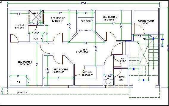
40 4.4 Procedure:
41 1. Set units type-architectural and precision-0-0½ 2. Create layers, text style, Dimension style 3. Draw a rectangle required template size using rectangular command, then Z enter E enter to zoom extend 4. Start drawing plan with line command one horizontal line and vertical line-while drawing line keep Ortho on 5. With offset command wall thickness and room dimensions are drawn 6. Use Trim command at every junction and excess lines 7. Provide doors and windows openings according to the sizes- use offset and trim command 8. Text and Dimensioning (common text height 9 - Main text height 14 )-Dimensioning commands preferable Linear, Aligned and leader. 9. Draw section mark use polyline command 10. Schedule of Door and windows- use text command 11. Using save command, the file having plan is saved by giving the Corresponding path name. 4.5 Results: The functional requirements of the single storeyed building is planned and the plan drawn in AutoCAD Pre lab questions 1. What is osnap? 2. What is plan? 3. List various commands used in this building plan? 4.7 Post lab questions 1. What is polyline? 2. What is common text height? 3. Thickness of wall? 4.8 Assignment question 1. Draw single storeyed building plan in Auto Cad 2016
42 Experiment No. 4.Drawing of plans of Buildings using software b) MULTI STOREYED 4.1 Aim: To draw the plan of single storeyed building using the various commands in AutoCAD 4.2 Software Used: AutoCADD Command Used And Their Description:- Zoom It is used to zoom the object created. Units Used to set the current format for units of measure. Line Line commands allows creating a line where the end points allow creating a line where the end points are dimensional co-ordinates. Line type using this command different type of lines can be used to draw object. Offset create a news object at a specified distance from an existing object or through a specified point. Fillet - This command is basically used for rounding off edges Trim trims off an object using cutting edges defined by other objects.2 Break removes only a part of an object. Arc Used to create an arc segment. Methods are: 1. 3 Points, 2. Start, Center, End 3. Start, Center, Angle 4. Center, Start, End 5. Center, Start, Angle 6. Start, Center, Length 7. Center, Start, Length 8. Start, End, Angle 9. Start, End, Radius
43 10. Start, End, Diameter 11. Continue Copy- Moves the selected objects from a given square to destination, learning a copy at the originally selected location. Rotate- rotate objects around a specified point Move- moves object to the destination place from the source place BHatch makes shaded patterns as matter of few picks and clicks away Extend elongates an object to a boundary defined by other objects Erase used to erase the unwanted objects Text creates text object with specified height and orientation osnap AutoCAD displays the object snaps tab in drafting setting dialog box. If we enter osnap at command prompt it presents options on the command line.
44 4.4 Procedure:
45 4.5 Results: The functional requirements of the multi storeyed building is planned and the plan drawn in AutoCAD Pre lab questions 1. What is meant by multi storyed building? 2. Define trim? 3. How to set page dimensions? 4.7 Post lab questions 1. Define break command 2. Different types of line commands? 4.8 Assignment questions 1. Draw multi storeyed building plan in Auto Cad 2016
46 Experiment No. 5 DEVELOPING SECTIONS AND ELEVATIONS FOR a) SINGLE STOREYED b) MULTI STOREYED a) Single storeyed Building 5.1 Aim: To draw the plan of single storeyed building using the various commands in AutoCAD 5.2 Software Used: AutoCADD Command Used And Their Description:- Zoom It is used to zoom the object created. Units Used to set the current format for units of measure. Line Line commands allows creating a line where the end points allow creating a line where the end points are dimensional co-ordinates. Line type using this command different type of lines can be used to draw object. Offset create a news object at a specified distance from an existing object or through a specified point. Fillet - This command is basically used for rounding off edges Trim trims off an object using cutting edges defined by other objects.2 Break removes only a part of an object. Arc Used to create an arc segment. Methods are: 1. 3 Points, 2. Start, Center, End 3. Start, Center, Angle 4. Center, Start, End 5. Center, Start, Angle 6. Start, Center, Length 7. Center, Start, Length
47 8. Start, End, Angle 9. Start, End, Radius 10. Start, End, Diameter 11. Continue Copy- Moves the selected objects from a given square to destination, learning a copy at the originally selected location. Rotate- rotate objects around a specified point Move- moves object to the destination place from the source place BHatch makes shaded patterns as matter of few picks and clicks away Extend elongates an object to a boundary defined by other objects Erase used to erase the unwanted objects Text creates text object with specified height and orientation osnap AutoCAD displays the object snaps tab in drafting setting dialog box. If we enter osnap at command prompt it presents options on the command line. 5.4 Procedure: 1. The elevation is drawn by extending the outer line of the plan using extend command and unwanted lines are erased using erase command. 2. The doors, windows, sunshade and parapet are drawn in same distance in elevation as drawn in same distance in the plan. 3. The section is drawn on the adjacent side of the elevation by extending the lines. 4. The various represtations of brickwork, sand filling and concrete are completed in the section using Bhatch command. 5. Using save command, the file having plan, elevation and section is saved by giving the Corresponding path name. 6. Using save command, the file having plan, elevation and section is saved by giving the Corresponding path name.
48 5.5 Results: The functional requirements of the multi storeyed building is planned, the section and elevation are drawn in AutoCAD Pre lab questions 1. How to use Hatch? 2. Define trim? 3. How to set page dimensions? 5.7 Post lab questions 1. Define break command 2. Define section? 3. Define elevation? 5.8 Assignment questions 1. Draw the plan of single storeyed building
49 Experiment No. 5 DEVELOPING SECTIONS AND ELEVATIONS FOR 5.1 Aim: b)multi storeyed Building To draw the plan of multi storeyed building using the various commands in AutoCAD 5.2 Software Used: AutoCADD Command Used And Their Description:- Zoom It is used to zoom the object created. Units Used to set the current format for units of measure. Line Line commands allows creating a line where the end points allow creating a line where the end points are dimensional co-ordinates. Line type using this command different type of lines can be used to draw object. Offset create a news object at a specified distance from an existing object or through a specified point. Fillet - This command is basically used for rounding off edges Trim trims off an object using cutting edges defined by other objects.2 Break removes only a part of an object. Arc Used to create an arc segment. Methods are: 1. 3 Points, 2. Start, Center, End 3. Start, Center, Angle 4. Center, Start, End 5. Center, Start, Angle 6. Start, Center, Length 7. Center, Start, Length
50 8. Start, End, Angle 9. Start, End, Radius 10. Start, End, Diameter 11. Continue Copy- Moves the selected objects from a given square to destination, learning a copy at the originally selected location. Rotate- rotate objects around a specified point Move- moves object to the destination place from the source place BHatch makes shaded patterns as matter of few picks and clicks away Extend elongates an object to a boundary defined by other objects Erase used to erase the unwanted objects Text creates text object with specified height and orientation osnap AutoCAD displays the object snaps tab in drafting setting dialog box. If we enter osnap at command prompt it presents options on the command line. 5.4 Procedure: 1. The elevation is drawn by extending the outer line of the plan using extend command and unwanted lines are erased using erase command. 2. The doors, windows, sunshade and parapet are drawn in same distance in elevation as drawn in same distance in the plan. 3. The section is drawn on the adjacent side of the elevation by extending the lines. 4. The various repetitions of brickwork, sand filling and concrete are completed in the section using Bhatch command. 5. Using save command, the file having plan, elevation and section is saved by giving the Corresponding path name. 6. Using save command, the file having plan, elevation and section is saved by giving the Corresponding path name.
51 5.5 Results: The functional requirements of the multi storeyed building is planned, the section and elevation are drawn in AutoCAD Pre lab questions 1. How to use Hatch? 2. Define trim? 3. Define Multi storey building? 5.7 Post lab questions 1. How to use text command? 2. Define section? 3. Define elevation? 5.8 Assignment questions 1. Draw the plan of multi storeyed building?
52 Experiment No. 6 DETAILING OF BUILDING COMPONENTS LIKE DOORS, WINDOWS, ROOF TRUSSES ETC. USING CAD SOFTWARE a)doors 6.1 Aim: To draw the plan, section and elevation of doors using the various commands in AutoCAD 6.2 Software Used: AutoCADD Command Used And Their Description:- Zoom It is used to zoom the object created. Units Used to set the current format for units of measure. Line Line commands allows creating a line where the end points allow creating a line where the end points are dimensional co-ordinates. Line type using this command different type of lines can be used to draw object. Offset create a news object at a specified distance from an existing object or through a specified point. Fillet - This command is basically used for rounding off edges Trim trims off an object using cutting edges defined by other objects.2 Break removes only a part of an object. Arc Used to create an arc segment. Methods are: 1. 3 Points, 2. Start, Center, End 3. Start, Center, Angle 4. Center, Start, End 5. Center, Start, Angle 6. Start, Center, Length 7. Center, Start, Length 8. Start, End, Angle 9. Start, End, Radius

53 10. Start, End, Diameter 11. Continue Copy- Moves the selected objects from a given square to destination, learning a copy at the originally selected location. Rotate- rotate objects around a specified point Move- moves object to the destination place from the source place BHatch makes shaded patterns as matter of few picks and clicks away Extend elongates an object to a boundary defined by other objects Erase used to erase the unwanted objects Text creates text object with specified height and orientation osnap AutoCAD displays the object snaps tab in drafting setting dialog box. If we enter osnap at command prompt it presents options on the command line. 6.4 Procedure:
54 1. The plan is drawn as per the door size and shown in above fig. 2. The elevation is drawn by extending the outer line of the plan using extend command and unwanted lines are erased using erase command. 3. The section is drawn on the adjacent side of the elevation by extending the lines. 4. The various represtations of frames, Aldrop, Door stopper, Handles etc.., are completed in the section using line and Bhatch commands. 5. Using save command, the file having plan, elevation and section is saved by giving the Corresponding path name. 6. Using save command, the file having plan, elevation and section is saved by giving the Corresponding path name. 6.5 Results: The planned, the section and elevation of the door is drawn in AutoCAD Pre lab questions 1. How to use Hatch? 2. Define trim? 3. define Multi storey building? 6.7 Post lab questions 1. How to use text command? 2. Define section? 3. Define elevation? 6.8 Assignment questions 1. Draw the section and elevation of the door?
55 Experiment No. 6 DETAILING OF BUILDING COMPONENTS LIKE DOORS, WINDOWS, ROOF TRUSSES ETC. USING CAD SOFTWARE 6.1 Aim: b) WINDOW To draw the plan, section and elevation of doors using the various commands in AutoCAD 6.2 Software Used: AutoCADD Command Used And Their Description:- Zoom It is used to zoom the object created. Units Used to set the current format for units of measure. Line Line commands allows creating a line where the end points allow creating a line where the end points are dimensional co-ordinates. Line type using this command different type of lines can be used to draw object. Offset create a news object at a specified distance from an existing object or through a specified point. Fillet - This command is basically used for rounding off edges Trim trims off an object using cutting edges defined by other objects.2 Break removes only a part of an object. Arc Used to create an arc segment. Methods are: 1. 3 Points, 2. Start, Center, End 3. Start, Center, Angle 4. Center, Start, End 5. Center, Start, Angle 6. Start, Center, Length 7. Center, Start, Length 8. Start, End, Angle

56 9. Start, End, Radius 10. Start, End, Diameter 11. Continue Copy- Moves the selected objects from a given square to destination, learning a copy at the originally selected location. Rotate- rotate objects around a specified point Move- moves object to the destination place from the source place BHatch makes shaded patterns as matter of few picks and clicks away Extend elongates an object to a boundary defined by other objects Erase used to erase the unwanted objects Text creates text object with specified height and orientation osnap AutoCAD displays the object snaps tab in drafting setting dialog box. If we enter osnap at command prompt it presents options on the command line 6.4 Procedure:
Dharmapuri LAB MANUAL. : B.E. - Civil Engineering Year & Semester : I Year / II Semester
 Dharmapuri 636 703 LAB MANUAL Regulation : 2013 Branch : B.E. - Civil Engineering Year & Semester : I Year / II Semester CE6261-COMPUTER AIDED DRAFTING AND MODELLING LABORATORY ICAL ENG VVIT DEPARTMENT
ARC By default AutoCAD will draw an ARC through three selected points. Options can be set at the start and within the command.
 DFTG 1309 Final Review Notes I. Draw commands: LINE (draws a series of lines) Valid input: Pick button Cartesian coordinates Absolute (2,3) Relative rectangular (@2,3) Relative polar (@ 2
06/17/02 Page 1 of 12
 Understanding the Graphical User Interface When you start AutoCAD, the AutoCAD window opens. The window is your design work space. It contains elements that you use to create your designs and to receive
COMPUTER AIDED DRAFTING LAB (333) SMESTER 4
 SMESTER 4") COMPUTER AIDED DRAFTING LAB (333) SMESTER 4 Introduction to Computer Aided Drafting: The method of preparing engineering drawing by using the computer software is known as Computer Aided Drafting (CAD).
COMPUTER AIDED DRAFTING LAB (333) SMESTER 4 Introduction to Computer Aided Drafting: The method of preparing engineering drawing by using the computer software is known as Computer Aided Drafting (CAD).
COURSE: INTRODUCTION TO CAD GRADES: UNIT: Measurement
 UNIT: Measurement - Students will demonstrate correctness in measuring using various scales and instruments. Demonstrate the various marks that make up a ruler including 1/16, 1/8, ¼ and ½. Assessment
INTRODUCTION to CAD ACAD BASICS. 2.1 Starting with ACAD. 2.2 Layout and sketching. 2.3 Drawing environment. 2.4 Elements of drawing
 INTRODUCTION to CAD ACAD BASICS 2.1 Starting with ACAD 2.2 Layout and sketching 2.3 Drawing environment 2.4 Elements of drawing 2.4.1 Draw commands 2.5 3D functions 2.6 Starting the drawing 2.6.1 Drawing
1: INTRODUCTION TO AUTOCAD
 AutoCAD syllabus 1: INTRODUCTION TO AUTOCAD Starting AutoCAD AutoCAD Screen Components Drawing Area Command Window Navigation bar Status bar Invoking Commands in AutoCAD Keyboard Ribbon Application Menu
Tutorial Guide to AutoCAD 2014
 Tutorial Guide to AutoCAD 2014 2D Drawing, 3D Modeling Shawna Lockhart SDC P U B L I C AT I O N S For Microsoft Windows Better Textbooks. Lower Prices. www.sdcpublications.com Visit the following websites
Tutorial Guide to AutoCAD 2013
 Tutorial Guide to AutoCAD 2013 2D Drawing, 3D Modeling Shawna Lockhart SDC P U B L I C AT I O N S Schroff Development Corporation For Microsoft Windows Better Textbooks. Lower Prices. www.sdcpublications.com
Tutorial Guide to AutoCAD 2015
 Tutorial Guide to AutoCAD 2015 2D Drawing, 3D Modeling Shawna Lockhart SDC P U B L I C AT I O N S For Microsoft Windows Better Textbooks. Lower Prices. www.sdcpublications.com Powered by TCPDF (www.tcpdf.org)
Isometric Drawings. Figure A 1
 A Isometric Drawings ISOMETRIC BASICS Isometric drawings are a means of drawing an object in picture form for better clarifying the object s appearance. These types of drawings resemble a picture of an
Basic 2D drawing skills in AutoCAD 2017
 Basic 2D drawing skills in AutoCAD 2017 This Tutorial is going to teach you the basic functions of AutoCAD and make you more efficient with the program. Follow all the steps so you can learn all the skills.
Chapter 7 Isometric Drawings
 Chapter 7 Isometric Drawings In this assignment, we are going to look at creating isometric drawings with AutoCAD. These drawing appear to be three dimensional but they are not. An AutoCAD isometric drawing
Lesson 6 2D Sketch Panel Tools
 Lesson 6 2D Sketch Panel Tools Inventor s Sketch Tool Bar contains tools for creating the basic geometry to create features and parts. On the surface, the Geometry tools look fairly standard: line, circle,
Dean Muccio. AutoCAD 2018 for the. Interior Designer. AutoCAD for Mac and PC SDC. Better Textbooks. Lower Prices.
 Dean Muccio AutoCAD 2018 for the Interior Designer AutoCAD for Mac and PC SDC P U B L I C AT I O N S Better Textbooks. Lower Prices. www.sdcpublications.com Powered by TCPDF (www.tcpdf.org) Visit the following
Dean Muccio AutoCAD Interior Designer. for the. AutoCAD for Mac and PC SDC. Better Textbooks. Lower Prices.
 Dean Muccio AutoCAD 2020 for the Interior Designer AutoCAD for Mac and PC SDC P U B L I C AT I O N S Better Textbooks. Lower Prices. www.sdcpublications.com Powered by TCPDF (www.tcpdf.org) Visit the following
AutoCAD Tutorial First Level. 2D Fundamentals. Randy H. Shih SDC. Better Textbooks. Lower Prices.
 AutoCAD 2018 Tutorial First Level 2D Fundamentals Randy H. Shih SDC PUBLICATIONS Better Textbooks. Lower Prices. www.sdcpublications.com Powered by TCPDF (www.tcpdf.org) Visit the following websites to
AutoCAD LT 2012 Tutorial. Randy H. Shih Oregon Institute of Technology SDC PUBLICATIONS. Schroff Development Corporation
 AutoCAD LT 2012 Tutorial Randy H. Shih Oregon Institute of Technology SDC PUBLICATIONS www.sdcpublications.com Schroff Development Corporation AutoCAD LT 2012 Tutorial 1-1 Lesson 1 Geometric Construction
COMPUTER AIDED DRAFTING (PRACTICAL) INTRODUCTION
 INTRODUCTION") LANDMARK UNIVERSITY, OMU-ARAN LECTURE NOTE: 3 COLLEGE: COLLEGE OF SCIENCE AND ENGINEERING DEPARTMENT: MECHANICAL ENGINEERING PROGRAMME: MCE 511 ENGR. ALIYU, S.J Course title: Computer-Aided Engineering
LANDMARK UNIVERSITY, OMU-ARAN LECTURE NOTE: 3 COLLEGE: COLLEGE OF SCIENCE AND ENGINEERING DEPARTMENT: MECHANICAL ENGINEERING PROGRAMME: MCE 511 ENGR. ALIYU, S.J Course title: Computer-Aided Engineering
Figure 1 - Motor City Electric Company Toolbar. LP Low Power HP High Power FA Fire Alarm C Communications LIT Lighting
 AutoCAD AutoCAD is the primary drawing program used by Motor City Electric Company. This program helps to engineer layouts of a buildings electrical equipment, lighting, and power that is to be sent out
SDC. AutoCAD LT 2007 Tutorial. Randy H. Shih. Schroff Development Corporation Oregon Institute of Technology
 AutoCAD LT 2007 Tutorial Randy H. Shih Oregon Institute of Technology SDC PUBLICATIONS Schroff Development Corporation www.schroff.com www.schroff-europe.com AutoCAD LT 2007 Tutorial 1-1 Lesson 1 Geometric
Introduction to AutoCAD 2012
 Page 1 Introduction to AutoCAD 2012 Alf Yarwood Answers to Multiple choice questions Chapter 1 1. The toolbar at the top of the AutoCAD 2012 window is: (a) The Draw toolbar (b) The Modify toolbar (c) The
Mastering AutoCAD 2D
 Course description: Mastering AutoCAD 2D Design and shape the world around you with the powerful, flexible features found in AutoCAD software, one of the world s leading 2D design applications. With robust
Principles and Practice
 Principles and Practice An Integrated Approach to Engineering Graphics and AutoCAD 2016 Randy H. Shih SDC PUBLICATIONS Better Textbooks. Lower Prices. www.sdcpublications.com Powered by TCPDF (www.tcpdf.org)
Computer Assisted Drafting (CAD) Level I & II
 Level I & II") Computer Assisted Drafting (CAD) Level I & II Program Description: Level I The Computer Assisted Drafting program prepares students for successful careers beginning as entry level design drafters in Architectural,
Computer Assisted Drafting (CAD) Level I & II Program Description: Level I The Computer Assisted Drafting program prepares students for successful careers beginning as entry level design drafters in Architectural,
SPRINGFIELD TECHNICAL COMMUNITY COLLEGE ACADEMIC AFFAIRS
 SPRINGFIELD TECHNICAL COMMUNITY COLLEGE ACADEMIC AFFAIRS Course Number: ARBT 125 Department: Architecture and Building Technology Course Title: Architectural CAD I Semester: Fall Year: 2013 Objectives/
AutoCAD LT 2009 Tutorial
 AutoCAD LT 2009 Tutorial Randy H. Shih Oregon Institute of Technology SDC PUBLICATIONS Schroff Development Corporation www.schroff.com Better Textbooks. Lower Prices. AutoCAD LT 2009 Tutorial 1-1 Lesson
GstarCAD Mechanical 2015 Help
 1 Chapter 1 GstarCAD Mechanical 2015 Introduction Abstract GstarCAD Mechanical 2015 drafting/design software, covers all fields of mechanical design. It supplies the latest standard parts library, symbols
THENI CE COMPUTER AIDED DESIGN & DRAFTING LABORATORY MANUAL
 NADAR SARASWATHI COLLEGE OF ENGINEERING AND TECHNOLOGY THENI CE 6711 - COMPUTER AIDED DESIGN & DRAFTING LABORATORY MANUAL PREPARED BY RECOMMENDED BY APPROVED BY STAFF INCHARGE HOD/CIVIL PRINCIPAL GENERAL
Arranging and Patterning Objects
 C H A P T E R Arranging and Patterning Objects Learning Objectives After completing this chapter, you will be able to do the following: Relocate objects using the MOVE tool. Change the angular positions
ENGINEERING GRAPHICS ESSENTIALS
 ENGINEERING GRAPHICS ESSENTIALS with AutoCAD 2012 Instruction Introduction to AutoCAD Engineering Graphics Principles Hand Sketching Text and Independent Learning CD Independent Learning CD: A Comprehensive
Assignment 12 CAD Mechanical Part 2
 Assignment 12 CAD Mechanical Part 2 Objectives In this assignment you will learn to apply the hidden lines, isometric snap, and ellipses commands along with commands previously learned.. General Hidden
with MultiMedia CD Randy H. Shih Jack Zecher SDC PUBLICATIONS Schroff Development Corporation
 with MultiMedia CD Randy H. Shih Jack Zecher SDC PUBLICATIONS Schroff Development Corporation WWW.SCHROFF.COM Lesson 1 Geometric Construction Basics AutoCAD LT 2002 Tutorial 1-1 1-2 AutoCAD LT 2002 Tutorial
CAYUGA COMMUNITY COLLEGE Division of Natural and Health Sciences, Mathematics and Technology ENGR 126 Computer Aided Design 4 Credit Hours
 CAYUGA COMMUNITY COLLEGE Division of Natural and Health Sciences, Mathematics and Technology ENGR 126 Computer Aided Design 4 Credit Hours COURSE DESCRIPTION Develop basic drafting skills using microcomputer
Principles and Practice:
 Principles and Practice: An Integrated Approach to Engineering Graphics and AutoCAD 2014 Randy H. Shih Multimedia Disc SDC PUBLICATIONS Better Textbooks. Lower Prices. www.sdcpublications.com Video presentations
SolidWorks 95 User s Guide
 SolidWorks 95 User s Guide Disclaimer: The following User Guide was extracted from SolidWorks 95 Help files and was not originally distributed in this format. All content 1995, SolidWorks Corporation Contents
Engineering & Computer Graphics Workbook Using SOLIDWORKS
 Engineering & Computer Graphics Workbook Using SOLIDWORKS 2017 Ronald E. Barr Thomas J. Krueger Davor Juricic SDC PUBLICATIONS Better Textbooks. Lower Prices. www.sdcpublications.com Powered by TCPDF (www.tcpdf.org)
IN-CLASS DEMONSTRATION. Introduction to AutoCAD 2011 and 2-Dimensional Drawing
 IN-CLASS DEMONSTRATION Introduction to AutoCAD 2011 and 2-Dimensional Drawing GISC, UNIVERSITY OF CALIFORNIA BERKELEY LABORATORY GOALS In this module you will be introduced to the AutoCAD 2011 interface
Copyrighted. Material. Copyrighted. Material. Copyrighted. Copyrighted. Material
 Engineering Graphics FREEHAND SKETCHING Introduction to Freehand Sketching Sketching is a very important technique for technical communication. Sketches can transfer ideas, instructions and information
Engineering & Computer Graphics Workbook Using SolidWorks 2014
 Engineering & Computer Graphics Workbook Using SolidWorks 2014 Ronald E. Barr Thomas J. Krueger Davor Juricic SDC PUBLICATIONS Better Textbooks. Lower Prices. www.sdcpublications.com Powered by TCPDF (www.tcpdf.org)
Chapter 2. Drawing Sketches for Solid Models. Learning Objectives
 Chapter 2 Drawing Sketches for Solid Models Learning Objectives After completing this chapter, you will be able to: Start a new template file to draw sketches. Set up the sketching environment. Use various
Object Snap, Geometric Constructions and Multiview Drawings
 Object Snap, Geometric Constructions and Multiview Drawings Sacramento City College EDT 310 EDT 310 - Chapter 6 Object Snap, Geometric Constructions and Multiview Drawings 1 Objectives Use OSNAP to create
Evaluation Chapter by CADArtifex
 The premium provider of learning products and solutions www.cadartifex.com EVALUATION CHAPTER 2 Drawing Sketches with SOLIDWORKS In this chapter: Invoking the Part Modeling Environment Invoking the Sketching
An Introduction to Autodesk Inventor 2011 and AutoCAD Randy H. Shih SDC PUBLICATIONS. Schroff Development Corporation
 An Introduction to Autodesk Inventor 2011 and AutoCAD 2011 Randy H. Shih SDC PUBLICATIONS www.sdcpublications.com Schroff Development Corporation An Introduction to Autodesk Inventor 2011 and AutoCAD 2011
LABORATORY MANUAL COMPUTER AIDED DESIGN LAB ME-211-F
 LABORATORY MANUAL COMPUTER AIDED DESIGN LAB ME-211-F List of Experiments:- Sl. No. Name of experiment Date Signature 01 02 Setting up of drawing environment by setting drawing limits, drawing units, naming
AutoCAD 2D I. Module 16. Isometric and Dimensioning. IAT Curriculum Unit PREPARED BY. January 2011
 AutoCAD 2D I Module 16 Isometric and Dimensioning PREPARED BY IAT Curriculum Unit January 2011 Institute of Applied Technology, 2011 Module 16 Auto CAD Self-paced Learning Modules AutoCAD 2D Isometric
Required Materials For complete material(s) information, refer to
 information, refer to") Butler Community College Science, Technology, Engineering, and Math Division Brett Trimpe Revised Spring 2016 Implemented Fall 2016 COURSE OUTLINE AutoCAD Basics Course Description EN 107. AutoCAD Basics.
Butler Community College Science, Technology, Engineering, and Math Division Brett Trimpe Revised Spring 2016 Implemented Fall 2016 COURSE OUTLINE AutoCAD Basics Course Description EN 107. AutoCAD Basics.
Module 2: Radial-Line Sheet-Metal 3D Modeling and 2D Pattern Development: Right Cone (Regular, Frustum, and Truncated)
") Inventor (5) Module 2: 2-1 Module 2: Radial-Line Sheet-Metal 3D Modeling and 2D Pattern Development: Right Cone (Regular, Frustum, and Truncated) In this tutorial, we will learn how to build a 3D model
Inventor (5) Module 2: 2-1 Module 2: Radial-Line Sheet-Metal 3D Modeling and 2D Pattern Development: Right Cone (Regular, Frustum, and Truncated) In this tutorial, we will learn how to build a 3D model
SKKK 1021 Engineering Drawing
 SKKK 1021 Engineering Drawing Introduction to AutoCAD Agus Arsad Introduction Overview & background Starting, interface & file system Basic drawing commands Basic editing commands View command Why use
Drawing a Living Room and Family Room Floorplan
 Appendix C Drawing a Living Room and Family Room Floorplan In this chapter, you will learn the following to World Class standards: Draw a Living Room and Family Room Floorplan Draw the Walls and Stairs
SYLLABUS. Apprenticeship Training Scheme
 SYLLABUS For the trade of CAD-CAM OPERATOR CUM PROGRAMMER UNDER Apprenticeship Training Scheme Government of India Ministry of Labour & Employment Directorate General of Employment & Training New Delhi-110001
Module 1H: Creating an Ellipse-Based Cylindrical Sheet-metal Lateral Piece
 Inventor (10) Module 1H: 1H- 1 Module 1H: Creating an Ellipse-Based Cylindrical Sheet-metal Lateral Piece In this Module, we will learn how to create an ellipse-based cylindrical sheetmetal lateral piece
Template Drawings. Template Drawings. AutoCAD Essentials
 AutoCAD Essentials Starting a new drawing using any CAD software requires a series of steps. Measurement units, sheet size, layer designations, text fonts and text sizes plus many more items must be set.
SAULT COLLEGE OF APPLIED ARTS AND TECHNOLOGY SAULT STE. MARIE, ONTARIO COURSE OUTLINE. Introduction to Computers and AutoCAD
 SAULT COLLEGE OF APPLIED ARTS AND TECHNOLOGY SAULT STE. MARIE, ONTARIO COURSE OUTLINE COURSE TITLE: Introduction to Computers and CODE NO. : SEMESTER: 2 PROGRAM: AUTHOR: Civil Engineering Technician Construction
Required Materials: Textbook: Grabowski, R. (2004). Using AutoCAD 2004: Basics. Clifton Park, N.Y: Delmar Learning.
. Using AutoCAD 2004: Basics. Clifton Park, N.Y: Delmar Learning.") Butler Community College Business, Technology, and Workforce Development COURSE OUTLINE AutoCAD Basics Mel Whiteside Spring 2004 Course Description: EN107. AutoCAD Basics. 3 hours credit. This course will
Butler Community College Business, Technology, and Workforce Development COURSE OUTLINE AutoCAD Basics Mel Whiteside Spring 2004 Course Description: EN107. AutoCAD Basics. 3 hours credit. This course will
Autocad Basics 7/28/2009. Chapter 14 - Learning Objectives
 Chapter 14 - Learning Objectives Autocad Basics Chapter 14 July 28, 2009 Use grips to stretch, copy, move, rotate, scale, and mirror objects. Edit objects using the Quick Properties panel and the Properties
Isometric Drawing Chapter 26
 Isometric Drawing Chapter 26 Sacramento City College EDT 310 EDT 310 - Chapter 26 - Isometric Drawing 1 Drawing Types Pictorial Drawing types: Perspective Orthographic Isometric Oblique Pictorial - like
Technical Drawing 101 with AutoCAD 2018
 Technical Drawing 101 with AutoCAD 2018 A Multidisciplinary Guide to Drafting Theory and Practice with Video Instruction Douglas Smith Antonio Ramirez Ashleigh Fuller SDC PUBLICATIONS Better Textbooks.
Module 1G: Creating a Circle-Based Cylindrical Sheet-metal Lateral Piece with an Overlaying Lateral Edge Seam And Dove-Tail Seams on the Top Edge
 Inventor (10) Module 1G: 1G- 1 Module 1G: Creating a Circle-Based Cylindrical Sheet-metal Lateral Piece with an Overlaying Lateral Edge Seam And Dove-Tail Seams on the Top Edge In Module 1A, we have explored
Completed project drawing (dimensions added for reference)
") CHAPTER 5 Fundamentals IV PROJECT EXERCISE This project exercise provides point-by-point instructions for setting up the drawing with layers and then creating the objects shown in the accompanying figure.
CHAPTER 5 Fundamentals IV PROJECT EXERCISE This project exercise provides point-by-point instructions for setting up the drawing with layers and then creating the objects shown in the accompanying figure.
First Level 2D Fundamentals
 AutoCAD 2016 Tutorial First Level 2D Fundamentals Randy H. Shih SDC PUBLICATIONS Better Textbooks. Lower Prices. www.sdcpublications.com Powered by TCPDF (www.tcpdf.org) Visit the following websites to
Fundamentals III CHAPTER PROJECT EXERCISE
 CHAPTER 4 Fundamentals III PROJECT EXERCISE This project exercise provides point-by-point instructions for setting up the drawing with layers and then creating the objects shown in Figure P4 1. FIGURE
Introduction to IntelliCAD 6
 Introduction to IntelliCAD 6 These notes explain the basic concepts and techniques for doing 2D line drawings, with dimensions, arranged onto sheets for printing, using the 6.4 or 6.6 versions of IntelliCAD
COMPUTER AIDED ENGINEERING DRAWING
 FIRST SEMESTER COMPUTER AIDED ENGINEERING DRAWING COMPUTER SIMULATION LAB DEPARTMENT OF ELECTRICAL ENGINEERING Prepared By: Checked By: Approved By: Engr. Sidra Jhangir Engr. M.Nasim Khan Dr.Noman Jafri
AutoCAD 2014 Tutorial - First Level: 2D Fundamentals
 AutoCAD 2014 Tutorial - First Level: 2D Fundamentals Randy H. Shih Multimedia Disc SDC PUBLICATIONS Schroff Development Corporation Better Textbooks. Lower Prices. www.sdcpublications.com Video presentations
Isometric Circles and Arcs
 AutoCAD and Its Applications BASICS Supplemental Material Chapter 4 Isometric Circles and Arcs On an isometric drawing, circles appear as ellipses and arcs as elliptical arcs. You must properly align isometric
Kankakee Community College
 Kankakee Community College Course prefix and number: DRFT 2114 Course title: AutoCAD I Credit hours: 4 Lecture hours: 2.5 Lab hours: 3 Semester: Spring 2015 Catalog description: This course introduces
Introduction to CATIA V5
 Introduction to CATIA V5 Release 17 (A Hands-On Tutorial Approach) Kirstie Plantenberg University of Detroit Mercy SDC PUBLICATIONS Schroff Development Corporation www.schroff.com Better Textbooks. Lower
Principles and Practice
 Principles and Practice An Integrated Approach to Engineering Graphics and AutoCAD 2011 Randy H. Shih Oregon Institute of Technology SDC PUBLICATIONS www.sdcpublications.com Schroff Development Corporation
Architecture 2012 Fundamentals
 Autodesk Revit Architecture 2012 Fundamentals Supplemental Files SDC PUBLICATIONS Schroff Development Corporation Better Textbooks. Lower Prices. www.sdcpublications.com Tutorial files on enclosed CD Visit
Creating Objects. In This Chapter
 Creating Objects In This Chapter 6 With the AutoCAD drawing tools, you can create a range of objects, from simple lines and circles to spline curves, ellipses, and hatched areas that change when their
Computer Aided Electrical Drawing Laboratory Manual. Table of Contents
 1 Sl No Computer Aided Electrical Drawing Laboratory Manual Table of Contents Name of the drawing Page Number 1. Basic drawing commands for autocad 4 2. Standard Electrical component symbols. 10 3. 4.
MODELING AND DESIGN C H A P T E R F O U R
 MODELING AND DESIGN C H A P T E R F O U R OBJECTIVES 1. Identify and specify basic geometric elements and primitive shapes. 2. Select a 2D profile that best describes the shape of an object. 3. Identify
After completing this lesson, you will be able to:
 LEARNING OBJECTIVES After completing this lesson, you will be able to: 1. Create a Circle using 6 different methods. 2. Create a Rectangle with width, chamfers, fillets and rotation. 3. Set Grids and Increment
Applications in Technical Drawing
 Applications in Technical Drawing Objectives: To use drawing aids in orthographic projection. To recognise the use of construction line in orthographic projection. To locate points using OSNAP and OTRACK.
Copyrighted. Material. Copyrighted. Material. Copyrighted. Material. Copyrighted. Material
 ENGINEERING & COMPUTER GRAPHICS WORKBOOK Using SolidWorks 2005 Ronald E. Barr Thomas J. Krueger Theodore A. Aanstoos Davor Juricic SDC PUBLICATIONS Schroff Development Corporation www.schroff.com www.schroff-europe.com
1.6.7 Add Arc Length Dimension Modify Dimension Value Check the Sketch Curve Connectivity
 Contents 2D Sketch... 1 1.1 2D Sketch Introduction... 1 1.1.1 2D Sketch... 1 1.1.2 Basic Setting of 2D Sketch... 2 1.1.3 Exit 2D Sketch... 4 1.2 Draw Common Geometry... 5 2.2.1 Points... 5 2.2.2 Lines
Dimensioning the Rectangular Problem
 C h a p t e r 3 Dimensioning the Rectangular Problem In this chapter, you will learn the following to World Class standards: 1. Creating new layers in an AutoCAD drawing 2. Placing Centerlines on the drawing
AutoCAD LT 2010 Tutorial
 AutoCAD LT 2010 Tutorial Randy H. Shih Oregon Institute of Technology SDC PUBLICATIONS Schroff Development Corporation www.schroff.com Better Textbooks. Lower Prices. AutoCAD LT 2010 Tutorial iii Table
AutoCAD 2020 Fundamentals
 Autodesk AutoCAD 2020 Fundamentals ELISE MOSS Autodesk Certified Instructor SDC PUBLICATIONS Better Textbooks. Lower Prices. www.sdcpublications.com Powered by TCPDF (www.tcpdf.org) Visit the following
Copyrighted. Material. Copyrighted. Material. Copyrighted. Material. Copyrighted. Material
 ENGINEERING & COMPUTER GRAPHICS WORKBOOK Using SolidWorks 2008 Ronald E. Barr Thomas J. Krueger Theodore A. Aanstoos Davor Juricic SDC PUBLICATIONS Schroff Development Corporation www.schroff.com Better
Autodesk AutoCAD 2013 Fundamentals
 Autodesk AutoCAD 2013 Fundamentals Elise Moss SDC P U B L I C AT I O N S Schroff Development Corporation Better Textbooks. Lower Prices. www.sdcpublications.com Visit the following websites to learn more
Fundamentals III PROJECT EXERCISE
 4 Fundamentals III PROJECT EXERCISE This project exercise provides point-by-point instructions for setting up the drawing with layers and then creating the objects shown in Figure P4 1. project EXERCISE
Making an Architectural Drawing Template
 C h a p t e r 8 Addendum: Architectural Making an Architectural Drawing Template In this chapter, you will learn the following to World Class standards:! Starting from Scratch for the Last time! Creating
Tools for Design. with VEX Robot Kit: Randy H. Shih Oregon Institute of Technology SDC PUBLICATIONS
 Tools for Design with VEX Robot Kit: AutoCAD 2011 and Autodesk Inventor 2011 2D Drawing 3D Modeling Hand Sketching Randy H. Shih Oregon Institute of Technology INSIDE: SUPPLEMENTAL FILES ON CD SDC PUBLICATIONS
Conquering the Rubicon
 Autodesk Inventor R10 Fundamentals: Conquering the Rubicon Elise Moss SDC PUBLICATIONS Schroff Development Corporation www.schroff.com www.schroff-europe.com Schroff Development Corporation P.O. Box 1334
1 Higher National Unit credit at SCQF level 7: (8 SCQF credit points at SCQF level 7)
") Higher National Unit specification General information Unit code: DW1E 34 Superclass: CH Publication date: August 2006 Source: Scottish Qualifications Authority Version: 03 (August 2016) Unit purpose This
Higher National Unit specification General information Unit code: DW1E 34 Superclass: CH Publication date: August 2006 Source: Scottish Qualifications Authority Version: 03 (August 2016) Unit purpose This
CAD Orientation (Mechanical and Architectural CAD)
") Design and Drafting Description This is an introductory computer aided design (CAD) activity designed to give students the foundational skills required to complete future lessons. Students will learn all
Design and Drafting Description This is an introductory computer aided design (CAD) activity designed to give students the foundational skills required to complete future lessons. Students will learn all
Copyrighted Material. Copyrighted Material. Copyrighted. Copyrighted. Material
 Engineering Graphics ORTHOGRAPHIC PROJECTION People who work with drawings develop the ability to look at lines on paper or on a computer screen and "see" the shapes of the objects the lines represent.
Table of Contents. Templates to download. Configuring your system Customizing your wheel mouse System Requirements
 Table of Contents Introduction About this book Templates to download About the Author Configuring your system Customizing your wheel mouse System Requirements Intro-1 Intro-1 Intro-1 Intro-2 Intro-8 Intro-9
Chapter 1. Creating, Profiling, Constraining, and Dimensioning the Basic Sketch. Learning Objectives. Commands Covered
 Chapter 1 Creating, Profiling, Constraining, and Dimensioning the Basic Sketch Learning Objectives After completing this chapter, you will be able to: Draw the basic outline (sketch) of designer model.
Tutorial 2: Setting up the Drawing Environment
 Drawing size With AutoCAD all drawings are done to FULL SCALE. The drawing limits will depend on the size of the items being drawn. For example if our drawing is the plan of a floor 23.8m X 15m then we
A TUTORIAL GUIDE TO FOR WINDOWS* Includes Coverage of. Addison-Wesley Publishing Company
 A TUTORIAL GUIDE TO AUTOCAD RELEASE 13 FOR WINDOWS* Includes Coverage of AutoVision and AutoCAD Designer Shawna D. Lockhart TT Addison-Wesley Publishing Company Reading, Massachusetts Menlo Park, California
AutoCAD 2018 Fundamentals
 Autodesk AutoCAD 2018 Fundamentals Elise Moss SDC PUBLICATIONS Better Textbooks. Lower Prices. www.sdcpublications.com Powered by TCPDF (www.tcpdf.org) Visit the following websites to learn more about
Advance Steel. Tutorial
 Advance Steel Tutorial Table of contents About this tutorial... 7 How to use this guide...9 Lesson 1: Creating a building grid...10 Step 1: Creating an axis group in the X direction...10 Step 2: Creating
COURSE OUTLINE. Course Number Course Title Credits DRA190 Introduction to Computer-Aided Drafting 2
 COURSE OUTLINE Course Number Course Title Credits DRA190 Introduction to Computer-Aided Drafting 2 Hours: Co- or Pre-requisite lecture/lab/other 1/2 Catalog description (2009-2011) Catalog Implementation
7/9/2009. Offset Tool. Offset Tool. Offsetting - Erasing the Original Object. Chapter 8 Construction Tools and Multiview Drawings
 Chapter 8 Construction Tools and Multiview Drawings Use the OFFSET tool to draw parallel lines and curves. Mark points on objects at equal lengths using the DIVIDE tool. Set designated increments on an
Chapter 6 Title Blocks
 Chapter 6 Title Blocks In previous exercises, every drawing started by creating a number of layers. This is time consuming and unnecessary. In this exercise, we will start a drawing by defining layers
AEROPLANE. Create a New Folder in your chosen location called Aeroplane. The four parts that make up the project will be saved here.
 AEROPLANE Prerequisite Knowledge Previous knowledge of the following commands is required to complete this lesson. Sketching (Line, Rectangle, Arc, Add Relations, Dimensioning), Extrude, Assemblies and