Computer Aided Drawing: An Overview
|
|
|
- Anis Ramsey
- 5 years ago
- Views:
Transcription
1 Computer Aided Drawing: An Overview Dr. H. Hirani Department of Mechanical Engineering INDIAN INSTITUTE OF TECHNOLOGY BOMBAY Powai, Mumbai-76
2 Drawing: Machine/ Engineering/ Technical Drawing is a universal language. It communicates information faster and more clearly than the spoken words. Industrial drawing allows viewers to imagine a building or machine before it is built. During Industrial Revolutions many men were trained strictly as draftsmen. Some had engineering or production skills, but many more were copyists.
3 Advantages of CAD over manual drawing Difference between a business report written using Typewriter and Computer? If Boss needs some changes? If paper and printing is costly? If there is a bit of change in two reports? If a neat report is demanded? If standards* are defined? *ANSI Y14 American National Standard Drafting Manual

4 2-D D versus 3-D 3 D drawings D: A concept of displaying real-world objects on a flat surface showing only height and width. This system uses only the X and Y axes. D: A way of displaying real-world object in a more natural way by adding depth to the height and width. This system uses the X Y and Z axes. 2-D: 3-D:


5 2-D D versus 3-D 3 D drawings.cont
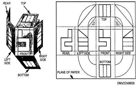
6 A pictorial drawing or photograph shows an object as it appears to the observer, but not as it is. Such a picture cannot describe the object fully, no matter from which direction it is viewed, because it does not show the exact shapes and sizes of the several parts.
7 2-D D versus 3-D 3 D drawings.cont

8 2-D D versus 3-D 3 D drawings.cont Parallel Projections
9
10 Necessary views are those that show best the essential contours or shapes and have minimum number of hidden lines. NOTE: Back, right side and bottom views can be deleted.
11 Why 3-D 3 D drawings? Exploration of new design ideas becomes easier. Improvement in product design cycle: Virtual assembly: Very large assemblies containing thousands of parts. Two way associativity Detection of interference Virtual Manufacturing: Fastest way to create a 2-D 2 D drawing. Better communication with non-engineers, sales and marketing personnel, production-line staff, vendors, partners, and clients. Static and dynamic analyses of assemblies.

12
13 Overview of Pro/Engineer Pro/ENGINEER is a computer graphics system for modeling various mechanical designs & for performing related design and manufacturing operations. The system uses a 3D solid modeling system as the core, and applies the feature-based, parametric modeling method. Pro/ENGINEER Conventional CAD Systems Parametric Model Feature-based Modeling Fixed-dimension Model Primitive-based Modeling

14 Overview of Pro/E Screen Layout Working window Only one window as current or active window. Message window: Text window. Display one line information statement ent about highlighted menu-item.
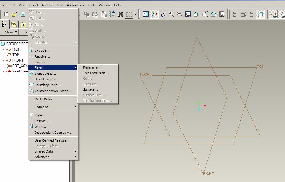
15 Overview of Pro/E.Menus Each Pro/ENGINEER object opens in a Graphics window. The menu bar, which is part of the Pro/ENGINEER main window, contains menus with options for creating, saving, and modifying models. File menu Provides options for opening, creating, saving, renaming, printing, importing, and exporting files. Edit menu Provides options for editing features, including modifying, redefining, rerouting, suppressing, resuming, editing patterns, and deleting a feature. View menu Options for controlling display of the model and display performance. Insert menu Options for creating datum features (i.e. points, axes, and planes) and features, such as: holes, chamfers, cuts, etc.
16 Overview of Pro/E.Files Working Directory File menu> Working Directory New File Select directory where part /assembly/ drawing file will be saved. Sketch: This 2-D 2 D Section mode can be accessed directly from the MODE menu or from the Part and Assembly modes. S2dxxx.sec prt sec Part: Prtxxx.prt Assembly: Asmxxx.asm Drawing: Drawxxx.drw drw
17
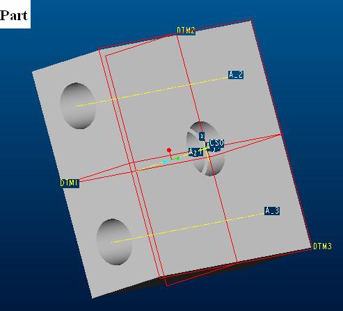
18 Overview of Pro/E.Model Information Obtaining a Feature List Info > Feature List Getting Information about a Specific Feature Info > Feature. Parent/Child Relations Info > Parent/Child (Parents/ Parents/Children > Highlight) Datum plane Model Information Info > Model Datum coordinate system Datum axis Reference geometries
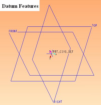
19 Reference Geometry Ex 1: Create a datum plane at 15 degree angle with front plane and passing through intersection of all three planes. Rename plane as Sketch_Plane
20 Reference Geometry Ex2: Create a series of datum points having dimensions: (0,10,0), (-5, 20,0), (-15,25,0),( (-45,30, 0), (-50,( 35, - 5), (-52,( 40, -10), (-( 52, 47, -30), (-52,( 47.75, -45). Create a smooth datum curve through all points.
21 3-D D Modeling of Simple Part Datum features Parent child relation Geometric features Dr. H. Hirani Department of Mechanical Engineering INDIAN INSTITUTE OF TECHNOLOGY BOMBAY Powai, Mumbai-76 hirani@me.iitb.ac.in
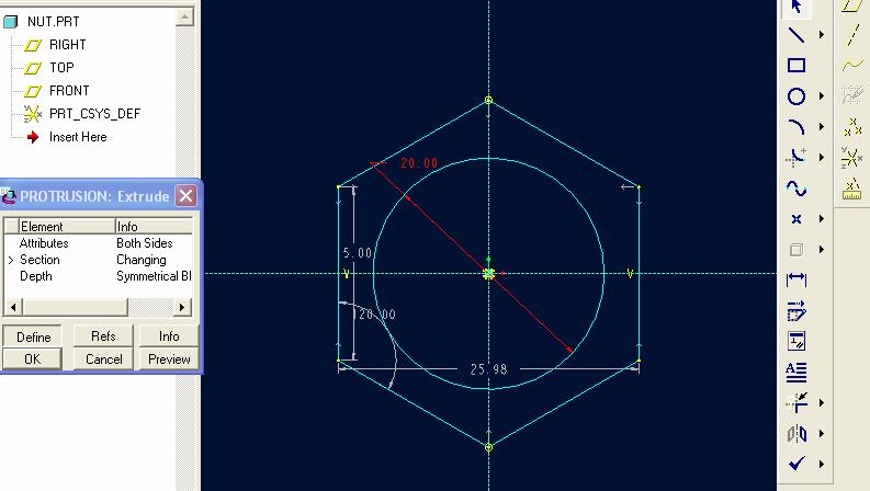
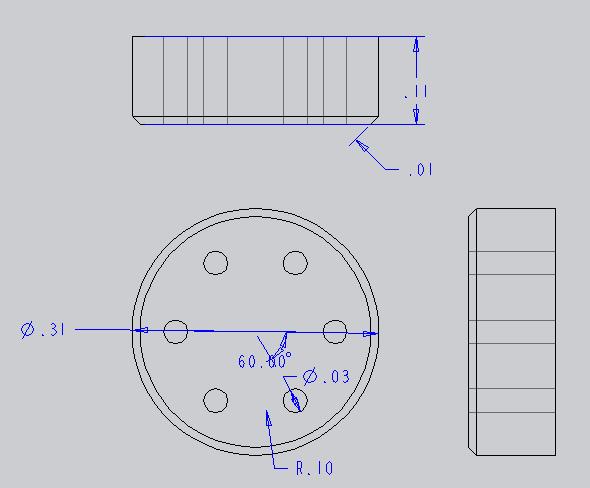
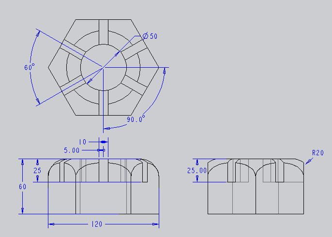
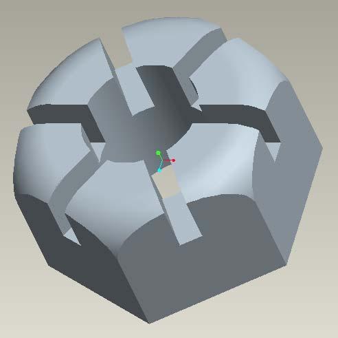
22 Ex: Draw a hexagonal nut with each side 15 mm and depth 15 mm
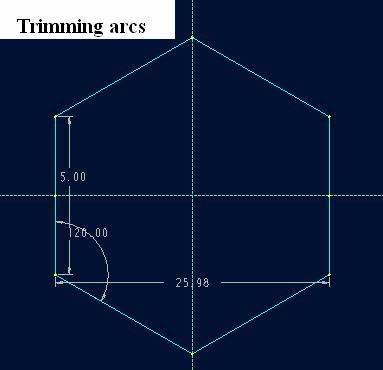
23 In hexagon each side is equal to the radius of circumscribed circle. Therefore in present exercise we will learn: How to draw a circle? How to draw centerlines? How to draw solid lines? How to trim arcs? How to make solid/hollow nut? How to create chamfer? Problem: Draw a hexagonal nut of 15mm side.

24 Step 1: Select working dir.

25 Step 2: File > New > part > Nut
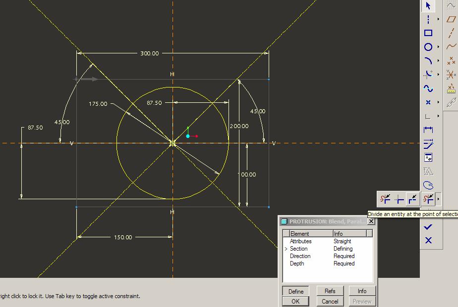
26 Step 3 EXTRUDE: Command raises the shape of a 2D outline into a 3D solid. For example, a circle would be extruded into a cylinder. This feature requires a 2-D cross-section, so Sketcher.

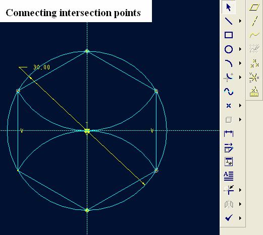
27 Step 4: Drawing circle and centerlines
28
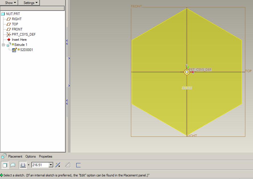
29 Completing sketch

30 Define depth = 15 mm
31

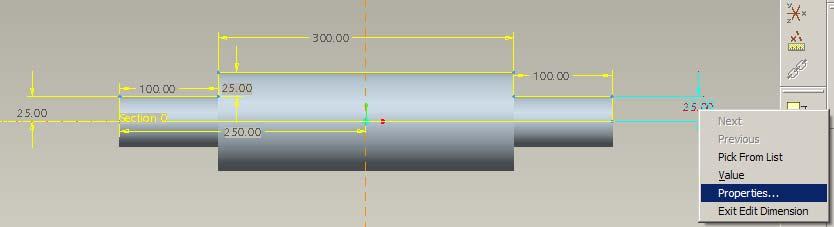
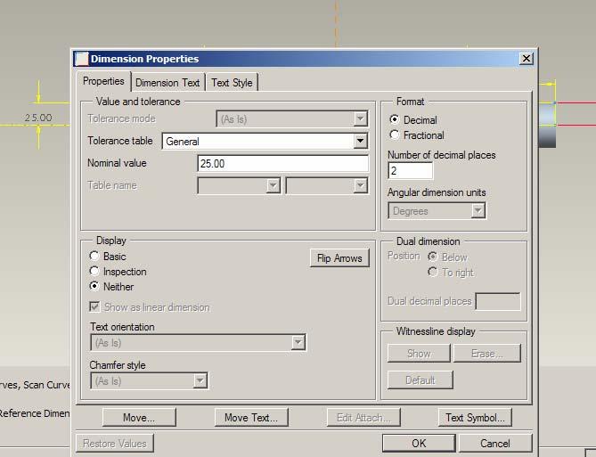
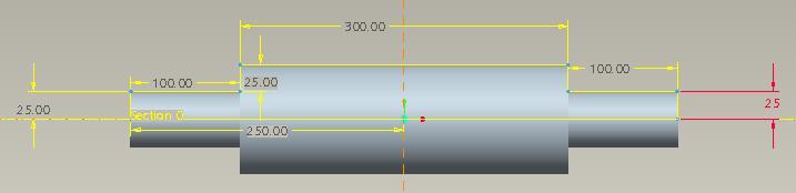
32 Alternative Method: using centerlines at 60 degree angles Dimensioning.
33

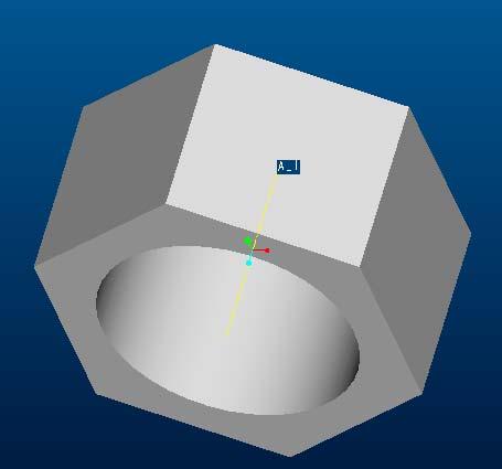
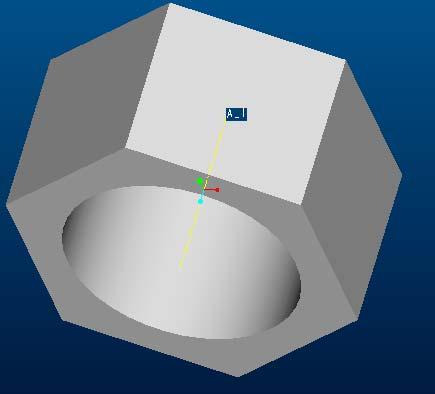
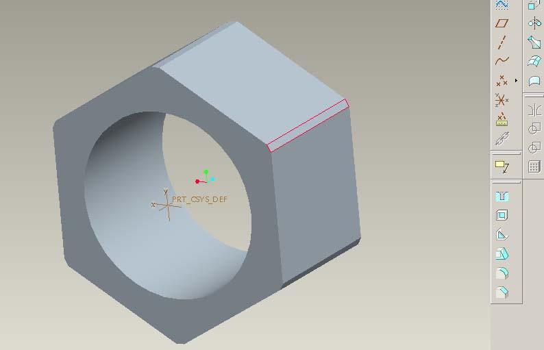
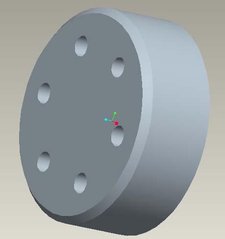
34 Create 6 chamfer features
35

36 Exercise I

37 Exercise II 150

38 Exercise III
39 Part Modeling Dr. H. Hirani Department of Mechanical Engineering INDIAN INSTITUTE OF TECHNOLOGY BOMBAY Powai, Mumbai-76
40 Different Blend Geometries
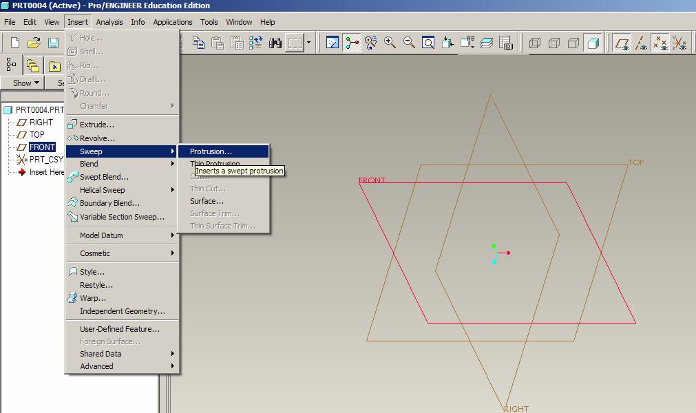
41 Sweeps

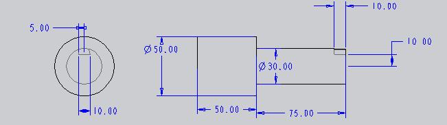
42 Part Modeling using Revolve Sketch on one side of centerline
43 Step I.. Choose Plane and Revolve tool

44 Step II: Sketch one side centerline and geometry given following figure Revolve it by 270 deg.

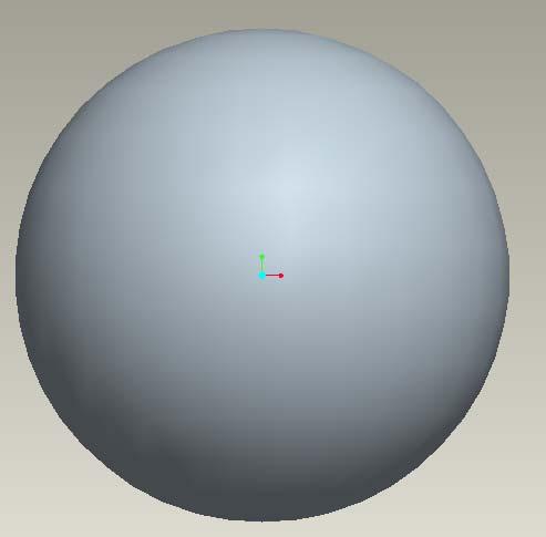
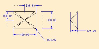
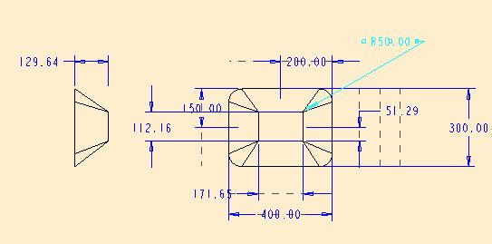
45 BLENDS Creation of Geometry between two or more sections of varying size, shape & location Parallel Blends Rotational Blends General Blends
46 Blending Cross-sections sections
47
48
49


50 Each section needs to have the same number of entities.
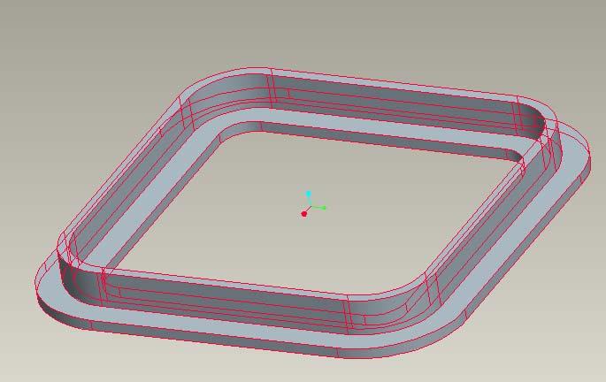
51 Sweeps
52 Step I

53 Step II.. Sketch trajectory
54 Step III
55 Step IV
56 Step V

57 Exercise 1

58 Exercise 2

59 Exercise 3

60 Exercise 4

61 Exercise 5

62 Exercise 6
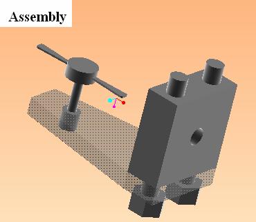
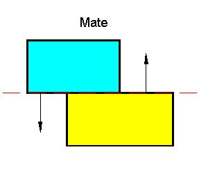
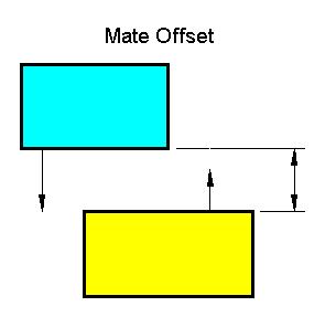
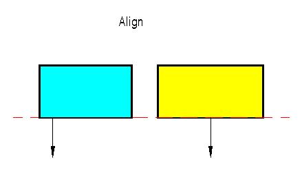
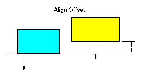
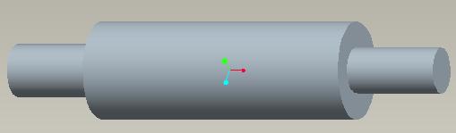
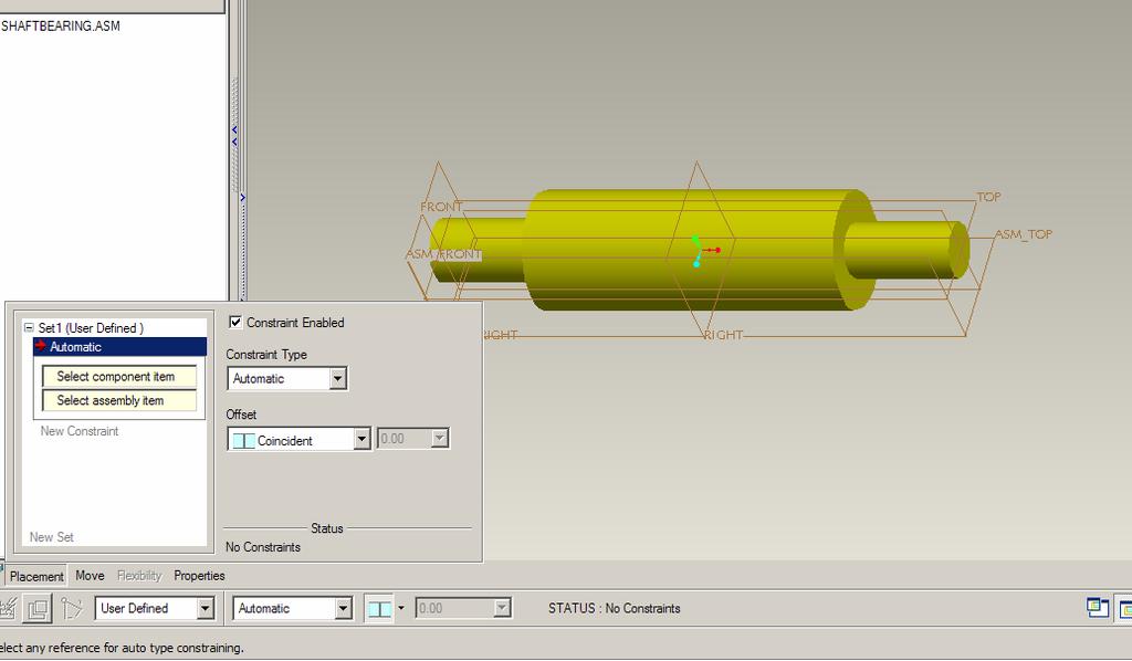
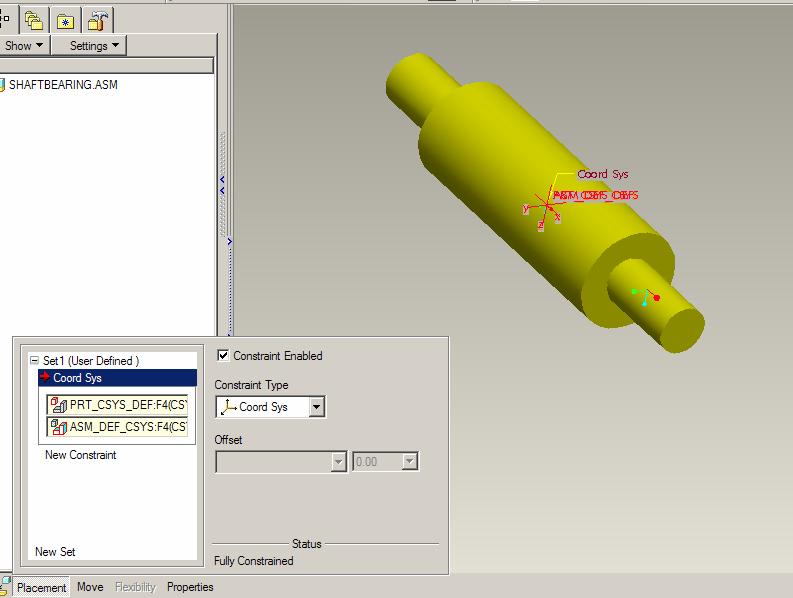
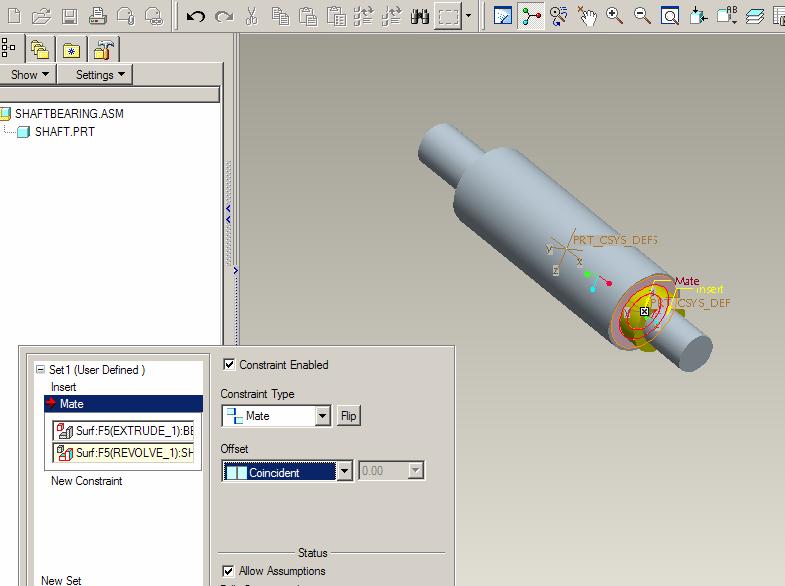
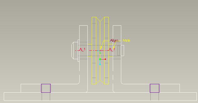
63 Assembly (fitting( fitting parts together) In the present session, we will learn to assemble Pro/E parts. The geometric relation between any two parts has six degrees of freedom:. In order to completely define the position of one part relative to another, we must constrain 3 translational and 3 rotational degrees of freedom. To reduce the degree of freedom of parts Pro/E uses following constraints: MATE -- MATE OFFSET ALIGN -- ALIGN OFFSET ORIENT -- INSERT NOTE: In Pro/E the order of constraints placement does not matter, since they are applied simultaneously. Pro/E provides information on fully constrained status.
64
65
66


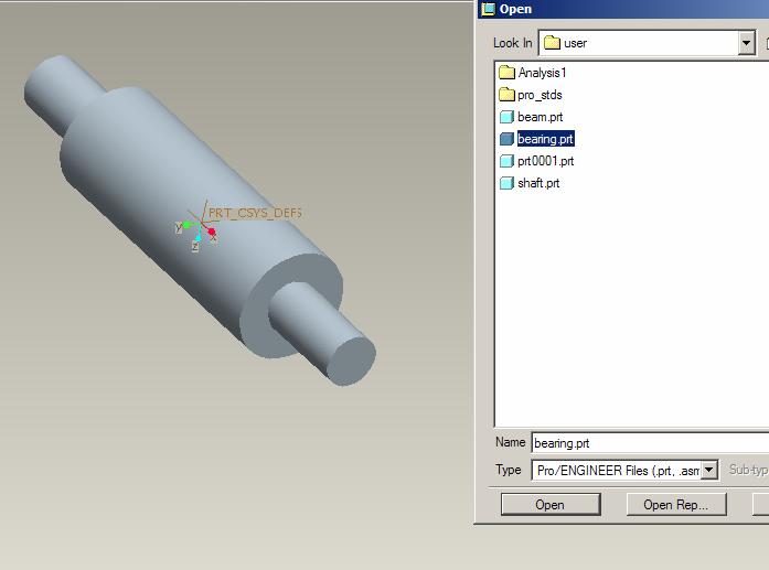
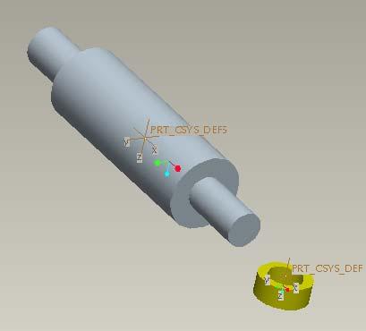
67 Placing Components Datum plane labels are preceded by an ASM_. Insert > Component > Assemble

68 In general, three constraints are needed to position one part with respect to the assembly datum. Full associatively reflects any changes made on a part in all assemblies where that part is used.
69
70
71
72
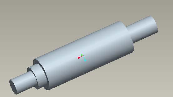
73 Drawing..

74 Default Views
75
76
77
78
79 Exercise
80

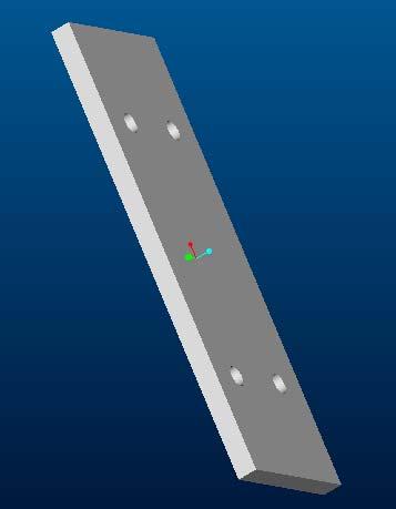
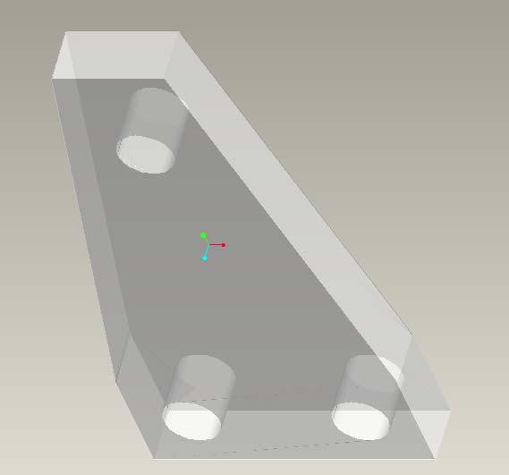
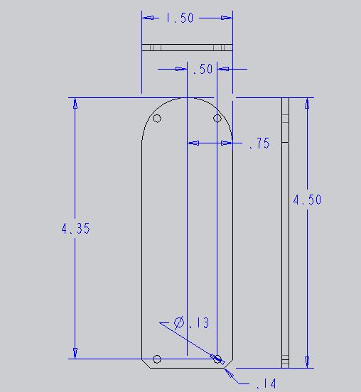
81 Exercise 8a: Base


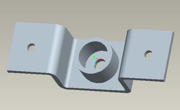
82 Exercise 8b: Pulley Support

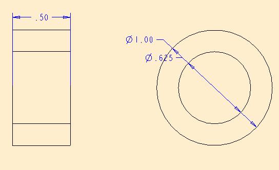
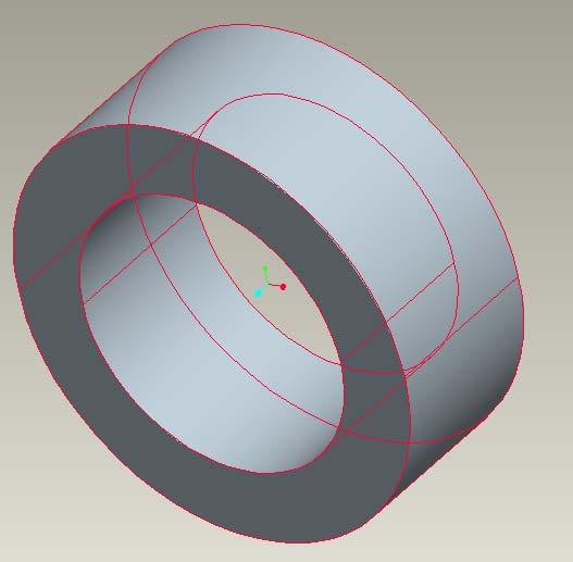
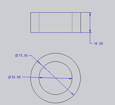
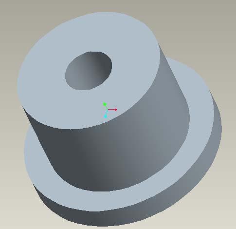
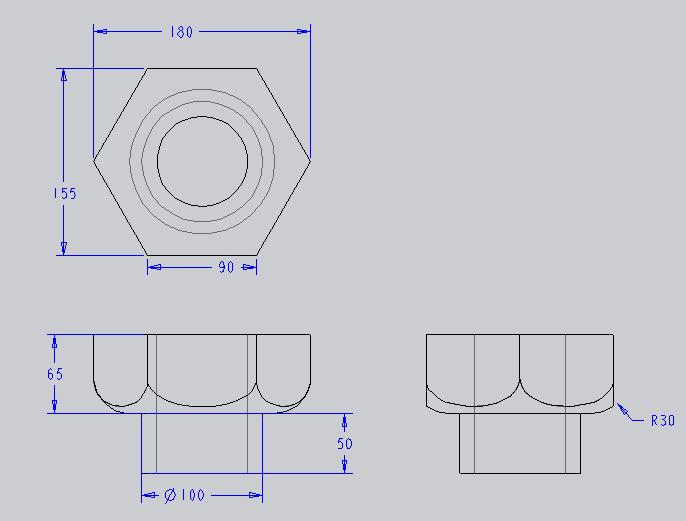
83 Exercise 9a: Bush

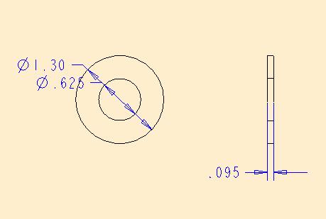
84 Exercise 9b:Washer


85 Exercise 9c: Axle Rod

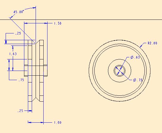
86 Exercise 10: Pulley

87 Exercise 11
88 Exercise
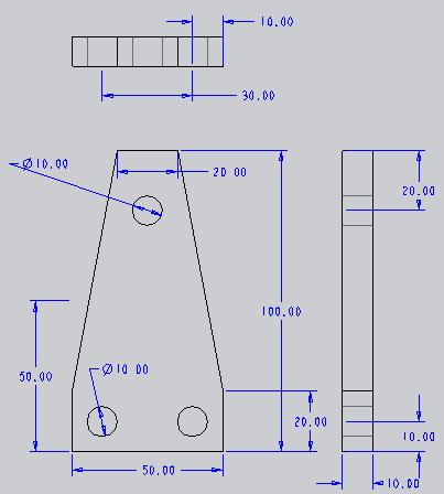
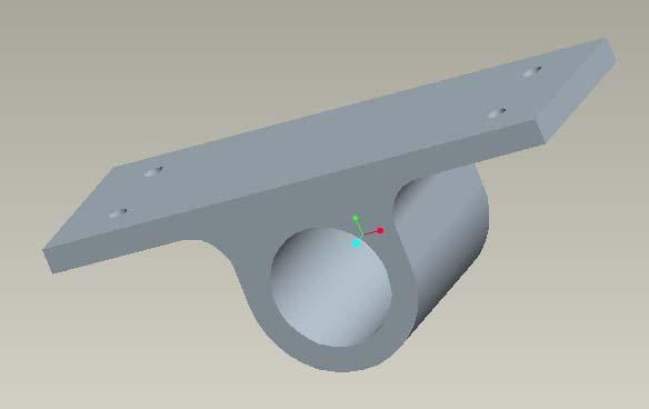
89 Bracket
90 Connector

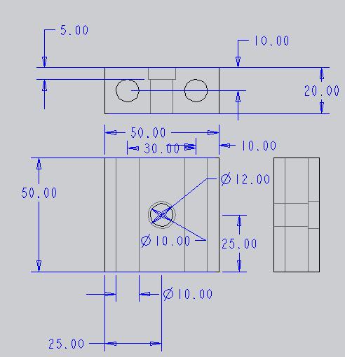
91 Base Block
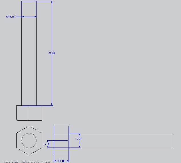
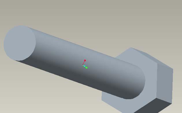
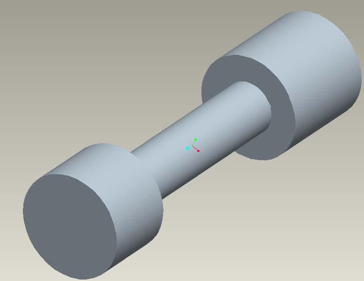
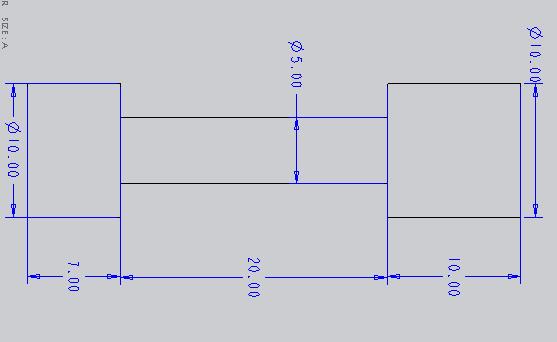
92 Bolt
93 Fan
94 End-Sem Sem-Paper 2007
95 Earpiece
96 Antenna
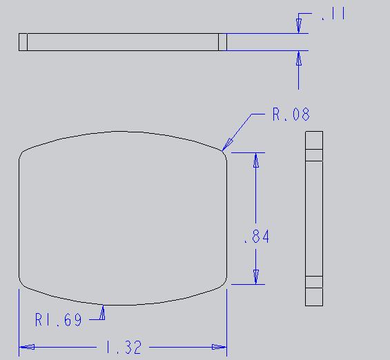
97 LENS
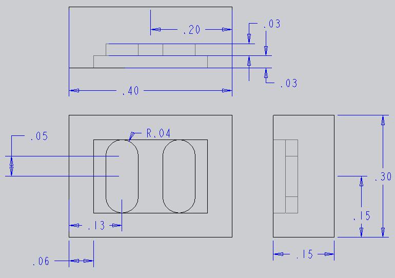
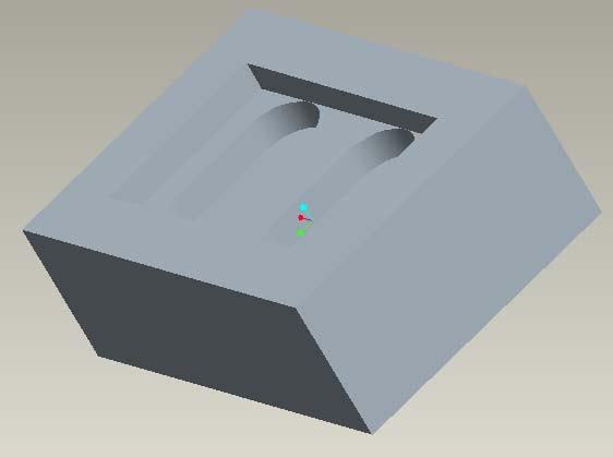
98 BOX
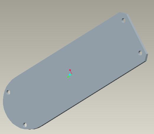
99 Board
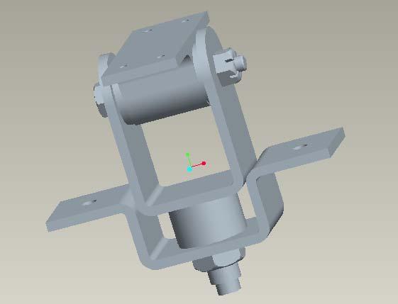
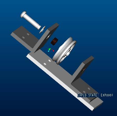
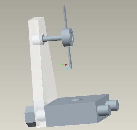
100 Assembly

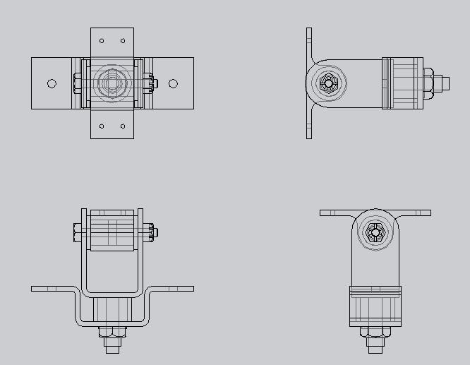
101 Exploded View of Assembly

102 Bracket _ Assembly

103 Bushing_Assembly
104 Castle Nut_Assembly
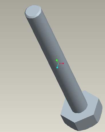
105 Hexagonalbolt_Assembly
106 Pivot_Assembly

107 Lockingnut_Assembly
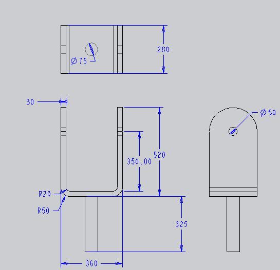
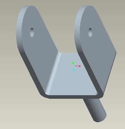
108 U_Support_Assembly
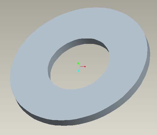

109 Washer_Assembly
110
Creo Parametric 4.0 Basic Design
 Creo Parametric 4.0 Basic Design Contents Table of Contents Introduction...1 Objective of This Textbook...1 Textbook Outline...2 Textbook Conventions...3 Exercise Files...3 System Configuration...4 Notes
Creo Parametric 2.0: Introduction to Solid Modeling. Creo Parametric 2.0: Introduction to Solid Modeling
 Creo Parametric 2.0: Introduction to Solid Modeling 1 2 Part 1 Class Files... xiii Chapter 1 Introduction to Creo Parametric... 1-1 1.1 Solid Modeling... 1-4 1.2 Creo Parametric Fundamentals... 1-6 Feature-Based...
Parametric Modeling with Creo Parametric 2.0
 Parametric Modeling with Creo Parametric 2.0 An Introduction to Creo Parametric 2.0 Randy H. Shih SDC PUBLICATIONS Schroff Development Corporation Better Textbooks. Lower Prices. www.sdcpublications.com
SOLIDWORKS 2015 and Engineering Graphics
 SOLIDWORKS 2015 and Engineering Graphics An Integrated Approach Randy H. Shih SDC PUBLICATIONS Better Textbooks. Lower Prices. www.sdcpublications.com Powered by TCPDF (www.tcpdf.org) Visit the following
and Engineering Graphics
 SOLIDWORKS 2018 and Engineering Graphics An Integrated Approach Randy H. Shih SDC PUBLICATIONS Better Textbooks. Lower Prices. www.sdcpublications.com Powered by TCPDF (www.tcpdf.org) Visit the following
Software Development & Education Center NX 8.5 (CAD CAM CAE)
") Software Development & Education Center NX 8.5 (CAD CAM CAE) Detailed Curriculum Overview Intended Audience Course Objectives Prerequisites How to Use This Course Class Standards Part File Naming Seed
Software Development & Education Center NX 8.5 (CAD CAM CAE) Detailed Curriculum Overview Intended Audience Course Objectives Prerequisites How to Use This Course Class Standards Part File Naming Seed
Nut and Bolt Tutorial
 Thread Representations Nut and Bolt Tutorial Parts to a Thread Thread Dimensioning Major Diameter Thread Series (IE UNC, UNF, ACME, etc) ½ - 13 UNC 2 A or B A = External B = Internal Threads per Inch Class
Introduction to Creo Parametric 2.0
 Introduction to Creo Parametric 2.0 Overview Course Code Course Length TRN-3902-T 5 Days In this course, you will learn core modeling skills and quickly become proficient with Creo Parametric 2.0. Topics
Part 2: Earpiece. Insert Protrusion (Internal Sketch) Hole Patterns Getting Started with Pro/ENGINEER Wildfire. Round extrusion.
 Hole Patterns Getting Started with Pro/ENGINEER Wildfire. Round extrusion.") Part 2: Earpiece 4 Round extrusion Radial pattern Chamfered edge To create this part, you'll use some of the same extrusion techniques you used in the lens part. The only difference in this part is that
Part 2: Earpiece 4 Round extrusion Radial pattern Chamfered edge To create this part, you'll use some of the same extrusion techniques you used in the lens part. The only difference in this part is that
Lesson 4 Holes and Rounds
 Lesson 4 Holes and Rounds 111 Figure 4.1 Breaker OBJECTIVES Sketch arcs in sections Create a straight hole through a part Complete a Sketched hole Understand the Hole Tool Use Info to extract information
Part 8: The Front Cover
 Part 8: The Front Cover 4 Earpiece cuts and housing Lens cut and housing Microphone cut and housing The front cover is similar to the back cover in that it is a shelled protrusion with screw posts extruding
Lesson 4 Extrusions OBJECTIVES. Extrusions
 Lesson 4 Extrusions Figure 4.1 Clamp OBJECTIVES Create a feature using an Extruded protrusion Understand Setup and Environment settings Define and set a Material type Create and use Datum features Sketch
Parametric Modeling. with. Autodesk Inventor Randy H. Shih. Oregon Institute of Technology SDC
 Parametric Modeling with Autodesk Inventor 2009 Randy H. Shih Oregon Institute of Technology SDC PUBLICATIONS Schroff Development Corporation www.schroff.com Better Textbooks. Lower Prices. iii Table of
Surface Modeling. Prerequisites. Stats
 Surface Modeling With all of its powerful feature creation tools, solid modeling is not capable of capturing the complex shapes. To capture such complex shapes, surface modeling techniques are widely used.
Parametric Modeling with
 Parametric Modeling with UGS NX 6 Randy H. Shih Oregon Institute of Technology SDC PUBLICATIONS Schroff Development Corporation www.schroff.com Better Textbooks. Lower Prices. Parametric Modeling with
COURSE CONTENTS FOR THE AVTS COURSES
 Revision: 00 LEARNING CONTENT Page 1 of 14 COURSE CONTENTS FOR THE AVTS COURSES AT CAD- CAM LAB, ATI, VIDYANAGAR, HYDERABAD Revision: 00 LEARNING CONTENT Page 2 of 14 III COURSE CODE CAD-01 IV COURSE TITLE
Autodesk Inventor 2016
 Parametric Modeling with Autodesk Inventor 2016 Randy H. Shih SDC PUBLICATIONS Better Textbooks. Lower Prices. www.sdcpublications.com Powered by TCPDF (www.tcpdf.org) Visit the following websites to learn
Advanced Modeling Techniques Sweep and Helical Sweep
 Advanced Modeling Techniques Sweep and Helical Sweep Sweep A sweep is a profile that follows a path placed on a datum. It is important when creating a sweep that the designer plans the size of the path
An Introduction to Autodesk Inventor 2011 and AutoCAD Randy H. Shih SDC PUBLICATIONS. Schroff Development Corporation
 An Introduction to Autodesk Inventor 2011 and AutoCAD 2011 Randy H. Shih SDC PUBLICATIONS www.sdcpublications.com Schroff Development Corporation An Introduction to Autodesk Inventor 2011 and AutoCAD 2011
Creo Parametric 1.0. for Engineers and Designers. CADCIM Technologies 525 St. Andrews Drive Schererville, IN 46375, USA (www.cadcim.
 Creo Parametric 1.0 for Engineers and Designers CADCIM Technologies 525 St. Andrews Drive Schererville, IN 46375, USA (www.cadcim.com) Contributing Author Sham Tickoo Professor Department of Mechanical
Tools for Design. with VEX Robot Kit: Randy H. Shih Oregon Institute of Technology SDC PUBLICATIONS
 Tools for Design with VEX Robot Kit: AutoCAD 2011 and Autodesk Inventor 2011 2D Drawing 3D Modeling Hand Sketching Randy H. Shih Oregon Institute of Technology INSIDE: SUPPLEMENTAL FILES ON CD SDC PUBLICATIONS
ENGINEERING GRAPHICS ESSENTIALS
 ENGINEERING GRAPHICS ESSENTIALS with AutoCAD 2012 Instruction Introduction to AutoCAD Engineering Graphics Principles Hand Sketching Text and Independent Learning CD Independent Learning CD: A Comprehensive
Creo Parametric & Creo Parametric 2.0
 51 Creo Parametric & Creo Parametric 2.0 Watch the Project Lecture Video before you start Angle Block Complete after Lesson 4 52 Figure Angle Block 1 Angle Block Angle Block This lesson project is a simple
Creo Revolve Tutorial
 Creo Revolve Tutorial Setup 1. Open Creo Parametric Note: Refer back to the Creo Extrude Tutorial for references and screen shots of the Creo layout 2. Set Working Directory a. From the Model Tree navigate
Essentials of SOLIDWORKS 2015 (4+ Days) * Ve-I Bonus! * File Management + SimulationXpress
 * Ve-I Bonus! * File Management + SimulationXpress") Essentials of SOLIDWORKS 2015 (4+ Days) * Ve-I Bonus! * File Management + SimulationXpress Overview What is SOLIDWORKS? Interface Tour View Manipulation Provides some background info on the SOLIDWORKS
Essentials of SOLIDWORKS 2015 (4+ Days) * Ve-I Bonus! * File Management + SimulationXpress Overview What is SOLIDWORKS? Interface Tour View Manipulation Provides some background info on the SOLIDWORKS
EN1740 Computer Aided Visualization and Design Spring 2012
 EN1740 Computer Aided Visualization and Design Spring 2012 1/31/2012 Brian C. P. Burke PLEASE WAIT TO LAUNCH PRO/E IF ALREADY OPENED, PLEASE CLOSE PLEASE WAIT TO LAUNCH PRO/E PLEASE CLOSE IF ALREADY OPENED
1. Open the Feature Modeling demo part file on the EEIC website. Ask student about which constraints needed to Fully Define.
 BLUE boxed notes are intended as aids to the lecturer RED boxed notes are comments that the lecturer could make Control + Click HERE to view enlarged IMAGE and Construction Strategy he following set of
Introduction to Autodesk Inventor User Interface Student Manual MODEL WINDOW
 Emmett Wemp EDTECH 503 Introduction to Autodesk Inventor User Interface Fill in the blanks of the different tools available in the user interface of Autodesk Inventor as your instructor discusses them.
CREO.1 MODELING A BELT WHEEL
 CREO.1 MODELING A BELT WHEEL Figure 1: A belt wheel modeled in this exercise. Learning Targets In this exercise you will learn: Using symmetry when sketching Using pattern to copy features Using RMB when
Lesson 6 2D Sketch Panel Tools
 Lesson 6 2D Sketch Panel Tools Inventor s Sketch Tool Bar contains tools for creating the basic geometry to create features and parts. On the surface, the Geometry tools look fairly standard: line, circle,
Education Curriculum Combined Specialist
 Education Curriculum Combined Specialist Invest your time in imagining next generation designs. Here s what we will teach you to give shape to your imagination. CATIA Combined Specialist Course CATIA Mechanical
MODELING AND DESIGN C H A P T E R F O U R
 MODELING AND DESIGN C H A P T E R F O U R OBJECTIVES 1. Identify and specify basic geometric elements and primitive shapes. 2. Select a 2D profile that best describes the shape of an object. 3. Identify
Up to Cruising Speed with Autodesk Inventor (Part 1)
") 11/29/2005-8:00 am - 11:30 am Room:Swan 1 (Swan) Walt Disney World Swan and Dolphin Resort Orlando, Florida Up to Cruising Speed with Autodesk Inventor (Part 1) Neil Munro - C-Cubed Technologies Ltd. and
11/29/2005-8:00 am - 11:30 am Room:Swan 1 (Swan) Walt Disney World Swan and Dolphin Resort Orlando, Florida Up to Cruising Speed with Autodesk Inventor (Part 1) Neil Munro - C-Cubed Technologies Ltd. and
Explanation of buttons used for sketching in Unigraphics
 Explanation of buttons used for sketching in Unigraphics Sketcher Tool Bar Finish Sketch is for exiting the Sketcher Task Environment. Sketch Name is the name of the current active sketch. You can also
Engineering Technology
 Engineering Technology Introduction to Parametric Modelling Engineering Technology 1 See Saw Exercise Part 1 Base Commands used New Part This lesson includes Sketching, Extruded Boss/Base, Hole Wizard,
Module 2.1, 2.2 Review. EF101 Analysis & Skills Module 2.3. Sketched Features and Operations. On-line Help Two Locations
 EF101 Analysis & Skills Module 2.3 Engineering Graphics Revolved Features Placed Features Work Features Module 2.1, 2.2 Review What are the three types of operations for adding features to the base feature?
Designing in Context. In this lesson, you will learn how to create contextual parts driven by the skeleton method.
 Designing in Context In this lesson, you will learn how to create contextual parts driven by the skeleton method. Lesson Contents: Case Study: Designing in context Design Intent Stages in the Process Clarify
Alternatively, the solid section can be made with open line sketch and adding thickness by Thicken Sketch.
 Sketcher All feature creation begins with two-dimensional drawing in the sketcher and then adding the third dimension in some way. The sketcher has many menus to help create various types of sketches.
Feature-Based Modeling and Optional Advanced Modeling. ENGR 1182 SolidWorks 05
 Feature-Based Modeling and Optional Advanced Modeling ENGR 1182 SolidWorks 05 Today s Objectives Feature-Based Modeling (comprised of 2 sections as shown below) 1. Breaking it down into features Creating
Table of Contents. Dedication Preface. Chapter 1: Introduction to CATIA V5-6R2015. Chapter 2: Drawing Sketches in the Sketcher Workbench-I.
 Table of Contents Dedication Preface iii xvii Chapter 1: Introduction to CATIA V5-6R2015 Introduction to CATIA V5-6R2015 1-2 CATIA V5 Workbenches 1-2 System Requirements 1-4 Getting Started with CATIA
COMPUTER AIDED ENGINEERING DESIGN (BFF2612) PART DESIGN Sketch Based Features
 PART DESIGN Sketch Based Features") COMPUTER AIDED ENGINEERING DESIGN (BFF2612) PART DESIGN Sketch Based Features by Dr. Mohd Nizar Mhd Razali Faculty of Manufacturing Engineering mnizar@ump.edu.my MODELLING STRATEGIES Determine model type
COMPUTER AIDED ENGINEERING DESIGN (BFF2612) PART DESIGN Sketch Based Features by Dr. Mohd Nizar Mhd Razali Faculty of Manufacturing Engineering mnizar@ump.edu.my MODELLING STRATEGIES Determine model type
Part Design. Sketcher - Basic 1 13,0600,1488,1586(SP6)
") Part Design Sketcher - Basic 1 13,0600,1488,1586(SP6) In this exercise, we will learn the foundation of the Sketcher and its basic functions. The Sketcher is a tool used to create two-dimensional (2D)
Part Design Sketcher - Basic 1 13,0600,1488,1586(SP6) In this exercise, we will learn the foundation of the Sketcher and its basic functions. The Sketcher is a tool used to create two-dimensional (2D)
SolidWorks Part I - Basic Tools SDC. Includes. Parts, Assemblies and Drawings. Paul Tran CSWE, CSWI
 SolidWorks 2015 Part I - Basic Tools Includes CSWA Preparation Material Parts, Assemblies and Drawings Paul Tran CSWE, CSWI SDC PUBLICATIONS Better Textbooks. Lower Prices. www.sdcpublications.com Powered
Starting a New Drawing with a Title Block and Border
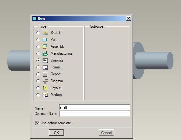
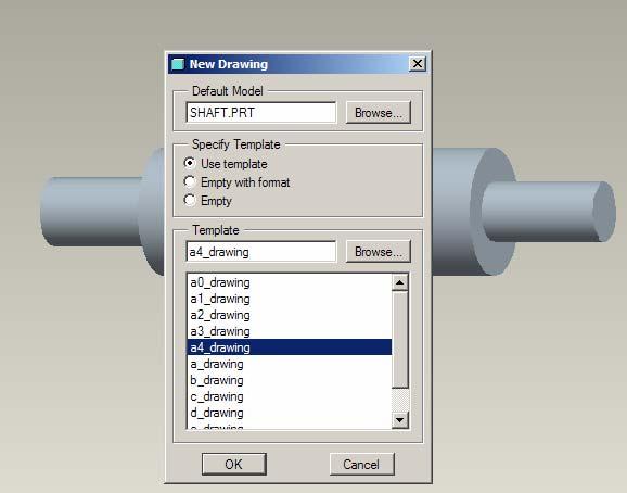
 Starting a New Drawing with a Title Block and Border From the File menu select New. Within the New file menu toggle the option Drawing, name the file and turn Off the toggle Use Default Template. Select
Tutorial Guide to AutoCAD 2014
 Tutorial Guide to AutoCAD 2014 2D Drawing, 3D Modeling Shawna Lockhart SDC P U B L I C AT I O N S For Microsoft Windows Better Textbooks. Lower Prices. www.sdcpublications.com Visit the following websites
Using Siemens NX 11 Software. The connecting rod
 Using Siemens NX 11 Software The connecting rod Based on a Catia tutorial written by Loïc Stefanski. At the end of this manual, you should obtain the following part: 1 Introduction. Start NX 11 and open
Shaft Hanger - SolidWorks
 ME-430 INTRODUCTION TO COMPUTER AIDED DESIGN Shaft Hanger - SolidWorks BY: DR. HERLI SURJANHATA ASSIGNMENT Submit TWO isometric views of the Shaft Hanger with your report, 1. Shaded view of the trimetric
Tutorial Guide to AutoCAD 2013
 Tutorial Guide to AutoCAD 2013 2D Drawing, 3D Modeling Shawna Lockhart SDC P U B L I C AT I O N S Schroff Development Corporation For Microsoft Windows Better Textbooks. Lower Prices. www.sdcpublications.com
CATIA Instructor-led Live Online Training Program
 Course Outline Introduction & Understanding to CATIA Environment Introduction & Understanding to CATIA interface Starting new file Understand the Sketcher workbench of CATIA V5 Start a new file in the
EN1740 Computer Aided Visualization and Design Spring /1/2012 Brian C. P. Burke
 EN1740 Computer Aided Visualization and Design Spring 2012 3/1/2012 Brian C. P. Burke Last time: Measure Shell Surfaces Best practices/appropriate Uses Parametric From standard features Tonight: Finish
Rotational Patterns of Pick and Place Features
 Rotational Patterns of Pick and Place Features The most efficient way to create multiple copies of one feature is to use the patterning function. Not only is it faster, but dimensioning is simplified,
Tutorial Guide to AutoCAD 2015
 Tutorial Guide to AutoCAD 2015 2D Drawing, 3D Modeling Shawna Lockhart SDC P U B L I C AT I O N S For Microsoft Windows Better Textbooks. Lower Prices. www.sdcpublications.com Powered by TCPDF (www.tcpdf.org)
Table of Contents. Lesson 1 Getting Started
 NX Lesson 1 Getting Started Pre-reqs/Technical Skills Basic computer use Expectations Read lesson material Implement steps in software while reading through lesson material Complete quiz on Blackboard
LABORATORY MANUAL COMPUTER AIDED DESIGN LAB
 LABORATORY MANUAL COMPUTER AIDED DESIGN LAB Sr. No 1 2 3 Experiment Title Setting up of drawing environment by setting drawing limits, drawing units, naming the drawing, naming layers, setting line types
Beginner s Guide to SolidWorks Level I
 Beginner s Guide to SolidWorks 2013 - Level I Parts, Assemblies, Drawings, Simulation Xpress Alejandro Reyes MSME, CSWP, CSWI SDC PUBLICATIONS Schroff Development Corporation Better Textbooks. Lower Prices.
Parametric Design 1
 Western Technical College 10606115 Parametric Design 1 Course Outcome Summary Course Information Description Career Cluster Instructional Level Total Credits 3 This course is designed to introduce students
Engineering Graphics UNIVERSITY OF TEXAS RIO GRANDE VALLEY JAZMIN LEY HISTORY OF ENGINEERING GRAPHICS GEOMETRIC CONSTRUCTION & SOLID MODELING
 Engineering Graphics UNIVERSITY OF TEXAS RIO GRANDE VALLEY JAZMIN LEY HISTORY OF ENGINEERING GRAPHICS GEOMETRIC CONSTRUCTION & SOLID MODELING Overview History of Engineering Graphics: Sketching, Tools,
Introducing SolidWorks
 Introducing SolidWorks SAAST Robotics 2008 SolidWorks Software Visually-based 3-D Mechanical design software Engineers and Designers use it to: Quickly sketch out ideas Experiment with features, dimensions
Teach Yourself UG NX Step-by-Step
 Teach Yourself UG NX Step-by-Step By Hui Zhang Ph.D., P.Eng. www.geocities.com/zhanghui1998 Table of Contents Chapter 1 Introduction... 1 1.1 UG NX User Interface... 1 1.2 Solid Modeling Fundamentals...
SolidWorks 95 User s Guide
 SolidWorks 95 User s Guide Disclaimer: The following User Guide was extracted from SolidWorks 95 Help files and was not originally distributed in this format. All content 1995, SolidWorks Corporation Contents
Clock Exercise (Inserting Planes)
") Clock Exercise (Inserting Planes) Prerequisite Knowledge To complete this exercise you will need to be familiar with Sketching, Applying relations, Extrude Boss/ Base, Extrude cut, Applying Textures, Renaming
Clock Exercise (Inserting Planes) Prerequisite Knowledge To complete this exercise you will need to be familiar with Sketching, Applying relations, Extrude Boss/ Base, Extrude cut, Applying Textures, Renaming
Beginner s Guide to SolidWorks Level I
 Beginner s Guide to SolidWorks 2014 - Level I Parts, Assemblies, Drawings, PhotoView 360 and Simulation Xpress Videos Now includes SolidWorks training videos Alejandro Reyes MSME, CSWP, CSWI Multimedia
CATIA V5 Workbook Release V5-6R2013
 CATIA V5 Workbook Release V5-6R2013 Richard Cozzens SDC PUBLICATIONS Better Textbooks. Lower Prices. www.sdcpublications.com Powered by TCPDF (www.tcpdf.org) Visit the following websites to learn more
Top Down Assembly Modeling Release Wildfire 2.0
 Top Down Assembly Modeling Release Wildfire 2.0 Note: Comprehensive Modeling Assignment This is a 30 point assignment as such takes the place of the final exam. Four Plate Mold Base, Inner Two Plates Begin
Model House Exercise-( Extrude)
") -( Extrude) Prerequisite knowledge Focus of the lesson Commands Used This lesson requires an understanding of using the sketch commands including Inserting a new sketch Adding sketch geometry Understanding
-( Extrude) Prerequisite knowledge Focus of the lesson Commands Used This lesson requires an understanding of using the sketch commands including Inserting a new sketch Adding sketch geometry Understanding
Introduction. Parametric Design
 Introduction This text guides you through parametric design using Creo Parametric. While using this text, you will create individual parts, assemblies, and drawings. Parametric can be defined as any set
SolidWorks 2014 Part I - Basic Tools
 SolidWorks 2014 Part I - Basic Tools Parts, Assemblies and Drawings Paul Tran CSWE, CSWI SDC PUBLICATIONS Better Textbooks. Lower Prices. www.sdcpublications.com Powered by TCPDF (www.tcpdf.org) Visit
M TE S Y S LT U A S S A
 Dress-Up Features In this lesson you will learn how to place dress-up features on parts. Lesson Contents: Case Study: Timing Chain Cover Design Intent Stages in the Process Apply a Draft Create a Stiffener
Activity 5.5a CAD Model Features Part 1
 Activity 5.5a CAD Model Features Part 1 Introduction In order to use CAD effectively as a design tool, the designer must have the skills necessary to create, edit, and manipulate a 3D model of a part in
Unit 4: Geometric Construction (Chapter4: Geometry For Modeling and Design)
") Unit 4: Geometric Construction (Chapter4: Geometry For Modeling and Design) DFTG-1305 Technical Drafting Instructor: Jimmy Nhan OBJECTIVES 1. Identify and specify basic geometric elements and primitive
Unit 4: Geometric Construction (Chapter4: Geometry For Modeling and Design) DFTG-1305 Technical Drafting Instructor: Jimmy Nhan OBJECTIVES 1. Identify and specify basic geometric elements and primitive
Training Guide Basics
 Training Guide Basics 2014, Missler Software. 7, Rue du Bois Sauvage F-91055 Evry, FRANCE Web: www.topsolid.com E-mail: info@topsolid.com All rights reserved. TopSolid Design Basics This information is
Solidworks: Lesson 4 Assembly Basics and Toolbox. UCF Engineering
 Solidworks: Lesson 4 Assembly Basics and Toolbox UCF Engineering Solidworks We have now completed the basic features of part modeling and it is now time to begin constructing more complex models in the
Learning. Autodesk Inventor 2019 SDC. Modeling, Assembly and Analysis. Randy H. Shih. Better Textbooks. Lower Prices.
 Learning Autodesk Inventor 2019 Modeling, Assembly and Analysis Randy H. Shih SDC PUBLICATIONS Better Textbooks. Lower Prices. www.sdcpublications.com Powered by TCPDF (www.tcpdf.org) Visit the following
SolidWorks 2013 Part I - Basic Tools
 SolidWorks 2013 Part I - Basic Tools Parts, Assemblies and Drawings Paul Tran CSWE, CSWI Supplemental Files SDC PUBLICATIONS Schroff Development Corporation Better Textbooks. Lower Prices. www.sdcpublications.com
SDC. SolidWorks Tutorial 2001Plus. A Competency Project Based Approach Utilizing 3D Solid Modeling. David C. Planchard & Marie P.
 2001Plus A Competency Project Based Approach Utilizing 3D Solid Modeling David C. Planchard & Marie P. Planchard SDC PUBLICATIONS www.schroff.com www.schroff-europe.com Project 2 Below are the desired
Conquering the Rubicon
 Autodesk Inventor R10 Fundamentals: Conquering the Rubicon Elise Moss SDC PUBLICATIONS Schroff Development Corporation www.schroff.com www.schroff-europe.com Schroff Development Corporation P.O. Box 1334
Multiviews and Auxiliary Views
 Multiviews and Auxiliary Views Multiviews and Auxiliary Views Objectives Explain orthographic and multiview projection. Identifying the six principal views. Apply standard line practices to multiviews
Introduction to Autodesk Inventor for F1 in Schools (Australian Version)
") Introduction to Autodesk Inventor for F1 in Schools (Australian Version) F1 in Schools race car In this course you will be introduced to Autodesk Inventor, which is the centerpiece of Autodesk s Digital
Introduction to Autodesk Inventor for F1 in Schools (Australian Version) F1 in Schools race car In this course you will be introduced to Autodesk Inventor, which is the centerpiece of Autodesk s Digital
Part Design Fundamentals
 Part Design Fundamentals 1 Course Presentation Objectives of the course In this course you will learn basic methods to create and modify solids features and parts Targeted audience New CATIA V5 Users 1
Lesson 16 Helical Sweeps and Annotations
 Lesson 16 Helical Sweeps and Annotations Figure 16.1 Helical Compression Spring Drawing OBJECTIVES Create a helical compression spring with a Helical Sweep Use sweeps to create hooks on extension springs
The Revolve Feature and Assembly Modeling
 The Revolve Feature and Assembly Modeling PTC Clock Page 52 PTC Contents Introduction... 54 The Revolve Feature... 55 Creating a revolved feature...57 Creating face details... 58 Using Text... 61 Assembling
< Then click on this icon on the vertical tool bar that pops up on the left side.
 Pipe Cavity Tutorial Introduction The CADMAX Solid Master Tutorial is a great way to learn about the benefits of feature-based parametric solid modeling with CADMAX. We have assembled several typical parts
Chapter 2. Drawing Sketches for Solid Models. Learning Objectives
 Chapter 2 Drawing Sketches for Solid Models Learning Objectives After completing this chapter, you will be able to: Start a new template file to draw sketches. Set up the sketching environment. Use various
Rotational Patterns of Sketched Features Using Datum Planes On-The-Fly
 Rotational Patterns of Sketched Features Using Datum Planes On-The-Fly Patterning a sketched feature (such as a slot, rib, square, etc.,) requires a slightly different technique. Why can t we create a
Inventor 2016 Essentials Plus
 Autodesk NEW Features a chapter on sheet metal design Inventor 2016 Essentials Plus Daniel T. Banach & Travis Jones SDC PUBLICATIONS Better Textbooks. Lower Prices. www.sdcpublications.com Powered by TCPDF
SolidWorks Part I - Basic Tools SDC. Includes. Parts, Assemblies and Drawings. Paul Tran CSWE, CSWI
 SolidWorks 2015 Part I - Basic Tools Includes CSWA Preparation Material Parts, Assemblies and Drawings Paul Tran CSWE, CSWI SDC PUBLICATIONS Better Textbooks. Lower Prices. www.sdcpublications.com Powered
Tools for Design. Using AutoCAD 2016 and Autodesk Inventor 2016 SDC. Hand Sketching, 2D Drawing and 3D Modeling. Randy H. Shih
 Tools for Design Using AutoCAD 2016 and Autodesk Inventor 2016 Hand Sketching, 2D Drawing and 3D Modeling Randy H. Shih SDC PUBLICATIONS Better Textbooks. Lower Prices. www.sdcpublications.com Powered
Designing in the context of an assembly
 SIEMENS Designing in the context of an assembly spse01670 Proprietary and restricted rights notice This software and related documentation are proprietary to Siemens Product Lifecycle Management Software
Module 2: Radial-Line Sheet-Metal 3D Modeling and 2D Pattern Development: Right Cone (Regular, Frustum, and Truncated)
") Inventor (5) Module 2: 2-1 Module 2: Radial-Line Sheet-Metal 3D Modeling and 2D Pattern Development: Right Cone (Regular, Frustum, and Truncated) In this tutorial, we will learn how to build a 3D model
Inventor (5) Module 2: 2-1 Module 2: Radial-Line Sheet-Metal 3D Modeling and 2D Pattern Development: Right Cone (Regular, Frustum, and Truncated) In this tutorial, we will learn how to build a 3D model
Custom Pillow Block Design Protrusion, Cut, Round, Draft (Review) Drawing (Review) Inheritance Feature (New) Creo 2.0
 Drawing (Review) Inheritance Feature (New) Creo 2.0") Custom Pillow Block Design Protrusion, Cut, Round, Draft (Review) Drawing (Review) Inheritance Feature (New) Creo 2.0 Rotatable pdf files: Casting Machining Grease Fitting Boss The general design of the
Custom Pillow Block Design Protrusion, Cut, Round, Draft (Review) Drawing (Review) Inheritance Feature (New) Creo 2.0 Rotatable pdf files: Casting Machining Grease Fitting Boss The general design of the
Virtual components in assemblies
 Virtual components in assemblies Publication Number spse01690 Virtual components in assemblies Publication Number spse01690 Proprietary and restricted rights notice This software and related documentation
Objectives. Inventor Part Modeling MA 23-1 Presented by Tom Short, P.E. Munro & Associates, Inc
 Objectives Inventor Part Modeling MA 23-1 Presented by Tom Short, P.E. Munro & Associates, Inc To demonstrate most of the sketch tools and part features in : Inventor Release 6 And, to show logical techniques
Activity 5.2 Making Sketches in CAD
 Activity 5.2 Making Sketches in CAD Introduction It would be great if computer systems were advanced enough to take a mental image of an object, such as the thought of a sports car, and instantly generate
Dimensioning. Dimensions: Are required on detail drawings. Provide the shape, size and location description: ASME Dimensioning Standards
 Dimensioning Dimensions: Are required on detail drawings. Provide the shape, size and location description: - Size dimensions - Location dimensions - Notes Local notes (specific notes) General notes ASME
Introduction to ANSYS DesignModeler
 Lecture 4 Planes and Sketches 14. 5 Release Introduction to ANSYS DesignModeler 2012 ANSYS, Inc. November 20, 2012 1 Release 14.5 Preprocessing Workflow Geometry Creation OR Geometry Import Geometry Operations
Introduction to CATIA V5
 Introduction to CATIA V5 Release 17 (A Hands-On Tutorial Approach) Kirstie Plantenberg University of Detroit Mercy SDC PUBLICATIONS Schroff Development Corporation www.schroff.com Better Textbooks. Lower
Pro/E WILDFIRE, week6
 Pro/E WILDFIRE, week6 1. Set working directory 2. File>New>Name is lbrack 3. When you create the part, make sure that the back surface of the vertical plate is on the front datum plane, and the lower surface