Esthec. Terrace. Manual for Assembly and Installation
|
|
|
- Brooke Hunter
- 5 years ago
- Views:
Transcription


1 Esthec Terrace Manual for Assembly and Installation 0
2 Table of Content 1. Introduction Factsheet Part-description Esthec Terrace profile Esthec Terrace side-profile... 5 Assembly clips Assembly clip type A Assembly clip type B Assembly clip type C Clip assembly rail Spacer End cap Handling and preparations Handling after delivery Working environment Working clothes Surface preparations Backing structure preparations Assembly material Cutting Alignment Conditioned area and weather changes Final check Installation Pre-assembly of clip type A Installation of first row of assembly clips type A Click-Assembly of first Esthec Terrace Profile Fixation of assembly clip type A Click-Assembly of Esthec Terrace Profiles Installation of last row of assembly clips type A Click-Assembly of last Esthec Terrace Profile Assembly of clips type B or type C Assembly of the end cap Installation of support row of assembly clips type A o 5.11 Click-Assembly of an Esthec Terrace profile in 90 angle Result Cleaning protocol Esthec Green Cleaner Esthec Nano Sealer
3 1. Introduction This manual can be used for the installation of the Esthec Terrace system. Please study it carefully before starting with the installation process. First the specifications of the Esthec Terrace system are defined in the Esthec Terrace factsheet. After this, the content of a Esthec Terrace system is listed. Before starting with the installation, an instruction of the handling and preparations is given and every different part involved is listed. To finish a cleaning protocol is described for cleaning and protection of the Esthec Terrace. DISCLAIMER Precautions for use Esthec products should be stored, handled and used in accordance with good hygiene practices and in conformity with all appropriate legal regulations and responsibilities. It is the responsibility of the customer to properly and effectively assess possible risks associated with the use of our products. For the safe use of Esthec products please refer to the handling advice on Esthec packaging. Legal notes The information and, in particular, the recommendations, relating to the application and end-use of Esthec products are given in good faith based on current knowledge and experience of the products when properly stored, handled and applied under normal conditions. In practice, the differences in materials, substrates and actual site conditions are such that no warranty in respect of merchantability or of fitness for a particular purpose, nor any liability arising out of any legal relationship whatsoever, can be inferred either from this information, or from any recommendations, or from any other advice offered. The user of the product must test the product s suitability for the intended purpose or application. Esthec reserves the right to change the properties of its products. The proprietary rights of third parties must be observed. All orders are accepted subject to our current terms of sale and delivery. Users must always refer to the most recent issue of the product data sheet for the product concerned, a copy of which will be supplied on request. Acknowledgement We gratefully acknowledge that this manual could not have been produced without the valuable input from our customers, employees, photographers and others who have provided us with graphic material and have also given permission to gather more photographic images of, for instance, products, methods and processes. All trademarks are registered. Copyright Esthec 2010 Esthec No part of this manual may be copied, duplicated or reproduced in any form without prior written permission from Esthec. All rights reserved. 2
4 2. Factsheet Input Factsheet


5 3. Part-description The small amount of different parts which form the Esthec Terrace system make the assembly very simple and easy to execute. In this chapter all parts are listed and explained. Later on these parts will be mentioned in the chapters Handling and preparations and Installation. 3.1 Esthec Terrace profile An Esthec Terrace profile is produced out of a glass fibre reinforced composite, which is covered with a high quality Esthec top layer. By use of the glass fibre reinforced composite the Esthec Terrace profile has very high stiffness properties and still is a light weight. With the Esthec top layer all advantages of applying Esthec material are provided. The standard width of an Esthec Terrace profile is 100 mm 1. Esthec terrace profiles are produced in a standard length of 3,000 mm 1. The height is 21 mm. The weight of 1,000mm 1 Esthec terrace profile is approximately gr. The Esthec Terrace profile is produced in a dark grey/anthracite colour. Figure 1 Standard Esthec Terrace profile The shape of the Esthec Terrace profiles on each side is designed to be stiff but lightweight, and is optimised on each side to assemble all different assembly-parts. End cap Clip B/C Clip A/B/C Figure 2 Assembly detail Esthec Terrace profile 4
6 3.2 Esthec Terrace side-profile In some situations it is possible that one side of an Esthec Terrace profile is visable. For this situation, the Esthec Terrace side-profile is available. The Esthec Terrace side-profile is covered both on the top layer as well as on one side of the profile. The standard width of an Esthec Terrace side profile is 102 mm 1. The height is 21 mm. The terrace profiles are produced in a standard length of 3,000 mm. The weight of a 1,000mm terrace profile is approximately gr. Esthec 3.3 Assembly clips Figure 3 Esthec Terrace side-profile All different assembly clips are injection moulded parts produced out of Polyoxymethylene (POM). POM is an engineering thermoplastic used in precision parts requiring high stiffness, low friction and excellent dimensional stability. Three different assembly clips are available. Clip type A is to assemble two Esthec Terrace profiles linear to each other in the length direction. When using Clip type B or type Clip type C, an Esthec Terrace profile can be assembled in a 90 o angle on each end of the profile. Because all assembly clips are 2,5 mm thick they will increase the height of the Esthec Terrace by 2,5mm. The system height of the Esthec Terrace is 23,5mm Next to this, all different assembly clips provide a space of approximately 5 mm between each Esthec Terrace profile. To mount the assembly clips, holes with a diameter of 5mm are provided. A parker screw, or a specific screw which fits best to the backing material and the assembly clips, can be applied for mounting the clips. 5


7 3.3.1 Assembly clip type A This assembly clip type is marked on the bottom of the clip with the letter A. As mentioned, clip type A is to assemble two Esthec Terrace profiles linear in the length direction. The four semi-round elements will lock inside the round open shape of the Esthec Terrace profile. Figure 4 Clip type A Figure 5 Clip type A assembly Assembly clip type B This assembly clip is marked on the bottom of the clip with the letter B. As mentioned, with assembly o clip type B an Esthec Terrace profile can be assembled in a 90 angle on each end of the profile. On assembly clip type B, 2 semi-round elements are replaced by 2 slides. These 2 slides can be installed on the open end of each profile. An important difference between assembly clip type A and clip type B is the locking function of clip type B, provided by the 2 slides. When installed the Esthec Terrace profile cannot be removed without first removing the assembly clip type B. Furthermore, the end cap fits over this clip, and can be installed in the open end of the Esthec Terrace profile. When installed, the end cap covers the elements of clip type B which remain visual after this clip is inserted in the open end of the Esthec Terrace profile. Figure 6 Clip type B Figure 7 Clip type B assembly 6


8 3.3.3 Assembly clip type C This assembly clip is marked on the bottom of the clip with the letter C. The technical shape and all specifications of assembly clip type B are applied. The difference between assembly clip type B and assembly clip type C is shown in the figure below. Assembly clip type C is 3mm shorter than assembly clip type B. In this way assembly Clip type C can be applied when no end cap will be installed after the assembly clip is installed. In this way the same space of 5mm is provided between the Esthec Terrace profiles. Figure 8 Clip type C Figure 9 Left Clip type B Right Clip type C The locking function of the assembly clip as described for assembly type B is also provided in assembly clip type B Clip assembly rail In order to speed up the installation process Esthec developed an assembly rail for the clips to be fixed on. This rail can be pre-assembled with assembly clips before installation starts. In this way time will be saved for the installation of individual assembly clips. By installing the pre-assembled rail 10 assembly clips are installed in 1 time, leaving the required space in between for the Esthec Terrace profiles. 3.4 Spacer The spacer part is an injection moulded parts produced out of PolyOxyMethylene (POM). The spacer is 2,5 mm thick and can be installed under all three types of assembly clips. Also the spacers can be mounted onto each other to increase the height on this specific location. Figure 10 Spacer 7


9 A spacer part can be applies in different situations. It can be installed to increase the height below the Esthec Terrace. For instance, when installing on a flat surface, the spacer will provide more space below the Esthec Terrace so water can run more easy to available drains. Also spacers can be applied when the surface to install the Esthec Terrace on is not completely levelled. In this situation it is used to level the Esthec Terrace. Figure 11 Spacer assembly 1 Figure 12 Spacer assembly End cap The Esthec Terrace end cap part is an injection moulded parts produced out of Luran S. This engineering thermoplastic is the brand name for Styrolution s styrene acrylonitrile copolymers that have been impact-modified with acrylic ester rubber. The Luran S grades and their blends stand out for their resistance to weathering and uv-light, for their high ageing stability and good resistance to chemicals. As a result, Luran S is suitable for components that are exposed to sun, rain, wind weather but nevertheless have to exhibit a particularly high quality over the long term. The Luran S brands offer a broad spectrum of extraordinary properties. Figure 13 End cap with Esthec Terrace logo Figure 14 End cap assembly The Esthec Terrace end cap is 4mm thick and available with or without the Esthec Terrace logo. To install the end cap is inserted in the upper hole of the shape-design of the Esthec Terrace profile. As mentioned the Esthec Terrace end cap is installed over the assembly clip type B so it will cover both the open end as well as the assembly clip. Glue can be applied when the fixation of this part is found not to be enough. 8
10 4. Handling and preparations Before installation various important preparations are required. Also the right handling of the different assembly parts is important. 4.1 Handling after delivery Check if the packaging is still intact before opening it. Please contact Esthec before opening a damaged packaging. If the box is not damaged, a visual inspection should be performed. Please check the Esthec Terrace profiles for any damage or irregularities. When removing Esthec Terrace profiles out of the box, or when placing Esthec Terrace profiles on top of each other be sure not to move/scrape the GRP backing over the Esthec top layer. This will surfaces and GRP backings on GRP backings. This minimizes (but not exclude) the possibility for scratches. 4.2 Working environment Prior to the installation, the location where the Esthec Terrace will be installed should be clean. Because dust, sand and or other construction material can damage the terrace it is advised to work in a clean environment. Still, after installation the Esthec Terrace it should be cleaned and threated according to the cleaning protocol as described in this document. 4.3 Working clothes Installation of an Esthec Terrace must be executed wearing clean clothes and clean shoes. In order not to damage or dirty the Esthec Terrace unnecessarily, the technicians need to wear shoes with clean soles or use protective shoe covers. 4.4 Surface preparations When applying the terrace on a flat surface this surface should be levelled. Use a straight edge to check whether there are any bumps or other irregularities on the surface and to determine whether the surface is rough. Remove all irregularities and rough parts by sanding them down by hand or machine. If the irregularities are too large, the surface needs to be levelled. 4.5 Backing structure preparations When applying the Esthec Terrace on a backing construction, this construction should be provided and safely installed on the ground surface. A maximum span of 500 mm is safe to apply. Furthermore, every assembly clip must be installed on the backing structure. It is not adviced to keep assembly clips floating because this will decrease the locking function of the assembly clips. 4.6 Assembly material Because the assembly clips are produced in a black colour they are sometimes hard to separate from each other. Also Boxes of the assembly material are quite similar to each other. It is advised to separate the different parts before starting with the installation. Using labels will help you to indicate the different parts. To check, every assembly clip has the type number engraved in itself. This letter is to be found on the bottom of every assembly clip. 9
11 4.7 Cutting To keep the working environment/location clean, also during installation of the Esthec Terrace it is important to execute all required processes that might pollute the working space in a different location. So for instance, when cutting of the Esthec Terrace profiles is required, a cutting location must be applied on a safe distance from the location where the Esthec Terrace is installed. It is advised to use a detailed CAD drawing of the design of the total terrace. With this drawing the length can be calculated in which the profiles should be cut. In order to create a clean cut a diamond blade equipped crosscut saw must be applied. To remove the remaining splinters, a small sanding paper on a sanding block can be used. 4.8 Alignment A perpendicular must be applied to ensure the Esthec Terrace will be installed correctly. When this is not applied, the Esthec Terrace cannot be installed correctly. Use a carpenter's pencil to mark this line on the surface beneath the Esthec Terrace. 4.9 Conditioned area and weather changes The ambient temperature for installation is optimal around 20 C Final check To check if the preparations are executed properly, the following points should be observed to ensure that the installation can take place under optimal conditions: A. All Esthec Terrace should be visually checked and all different installation material must be marked. B. The surface to install the Esthec Terrace on needs to be levelled, tidy and visually clean; C. The backing structure (when applied) should be completely installed, levelled, prepared, mounted and checked. D. The design of the terrace should be clear (definitive outer contours); E. The clear spaces around the terrace need to be known; F. The alignment should be prepared; G. Details inside the terrace should be prepared (drains, corners etc.); H. There should be sufficient light available; I. The cutting location should be prepared. 10

12 5. Installation In this chapter the installation of an Esthec Terrace system is described. All different installation phases are explained step by step. After a short preparation of the different parts, first the Esthec Terrace profiles are assembled in the length direction linear to each other. By using assembly clip type A standard distance of 5mm is applied between every two profiles. After the installation of these profiles, the possibility to assemble profiles in a 90 o angle on the two sides of the Esthec Terrace, using assembly clip type B or C, is described. In this manual clip type B is applied. This makes it possible to explain how and when the end cap can be installed. For this installation the assembly rail mentioned in chapter is not used. 5.1 Pre-assembly of clip type A After cutting the profiles they first need to be prepared with assembly clips type A on one side of the Esthec Terrace profile. The maximum allowed distance between the assembly clips is 500 mm. Clip A Max.500mm Figure 15 Clip type A assemble For this installation the Esthec Terrace profiles are placed upside down. The clips can be assembled very easy. When putting enough pressure on the clip they can be pushed in to the Esthec Terrace profile. This click installation results in a pile of cutted Esthec Terrace profiles, installed with assembly clips type A on one side on every 500mm, leaving a space of 100 mm on every side of the profile. Figure 16 Esthec Terrace profiles prepared with clip A 11


13 5.2 Installation of first row of assembly clips type A The first row of assembly clips type A must be mounted on the backing support or on the base where the Esthec Terrace will be installed on. For this installation two parker screws or custom selected screws which fit best to the backing material, are applied. This clip is positioned to the inside of the Esthec Terrace so it will not be visual after installation. Figure 17 First row of assembly clips A aligned and installed For the installation the prepared alignments is very important. In this way it is secured that the total Terrace will be aligned correctly. When installing the first Esthec Terrace profile this first row will mount one side of the Esthec Terrace profile to the backing support or base. How the first Esthec Terrace profile should be positioned and how the other side must be fixed will be described in the next chapter. 5.3 Click-Assembly of first Esthec Terrace Profile As described. the first row of assembly clips type A and the last row of assembly clips type A, to install the first and last Esthec Terrace profile on, will be mounted with two parker screws per assembly clip. The other assembly clips type A, which will be installed in between, will be mounted with one parker screw. This parker screw is installed after the click installation of the Esthec Terrace profile onto the pre-installed first row of assembly clips type A. 1st row: 2 parker screws 2nd-3rd-.. row: 1 parker screw Figure 18 Installation of the 1st Esthec Terrace profile and last profiles 12

14 The first Esthec Terrace profiles is picked from the prepared Esthec Terrace profiles, and assembled / clicked into the first row of assembly clips type A. Again the alignment is important to check and the space on each side of the profile must be equal. Figure 19 Installation of the first Esthec Terrace profiles 5.4 Fixation of assembly clip type A After the click-installation of the first Esthec Terrace profile the visual assembly clips type A must be mounted to the backing support or on the base using one parker screws per clip. It is important to align all profiles so both ends are positioned correctly. Figure 20 Esthec Terrace profile installed 13

15 5.5 Click-Assembly of Esthec Terrace Profiles The installation of the Esthec Terrace profiles is continued with the other prepared Esthec Terrace profiles, until the last profile needs to be installed. For this profile the last row of assembly clips is required before this Esthec Terrace profile can be click-assembled. This will be described in the next chapter. Figure 21 Progress in the installation of the Esthec Terrace profiles 5.6 Installation of last row of assembly clips type A To position and pre-installation the last row of assembly clips type A it is advised to us a short part of Esthec Terrace profile. In this way the right location van be measured to install the assembly clips. Again, for this last row two parker screws can be applied. This clip is positioned to the inside of the Esthec Terrace so it will not be visual after installation. Figure 22 Detail view last row of assembly clips type A 14
16 5.7 Click-Assembly of last Esthec Terrace Profile When the last row of assembly clips type A are installed, the last Esthec Terrace profile can be click- assembled. Again, check carefully if both ends of the Esthec Terrace profile is aligned with the rest of the Esthec Terrace profiles. Figure 23 Clip type A for installation of last profile prepared This is the last action before starting with the installation of the Esthec Terrace profiles, which are o positioned in a 90 angle, and the installation of the end caps. Please note that is absolutely essential to install all assembly clips type A first before the assembly clips type B can be used. Figure 24 Esthec Terrace ready for Clip type B installation 15


17 5.8 Assembly of clips type B or type C In the situation where no end caps will be applied, assembly clip type C must be installed. As described in the part description, assembly clip type C is shorter than assembly clip type B so the space of 5 mm between the Esthec Terrace profile is maintained whether the end cap is applied or not. In the following example assembly clip type B is applied. Figure 25 Detail view clip type B Figure 26 Clip type B Installed When installed correctly, the aligned Terrace outside makes it possible to assembly clip type B on every open end. One assembly clip type B combines or mounts two Esthec Terrace profiles together. In the first and last Esthec Terrace profile an standalone assembly clip type B is installed. This clip is positioned to the inside of the Esthec Terrace so it will not be visual after installation. To finish this step, every assembly clip type B is mounted to the base or backing structure using one parker screw. When the parker screws are installed it must be noted that the deck is now mounted to the base of backing structure. It is not possible any longer to pull the Esthec terrace profiles out of the assembly clips type A. Please note that is absolutely essential to install all assembly clips type A first before the assembly clips type B can be used. 5.9 Assembly of the end cap Now it is possible to install the end cap. This part is inserted in the open ends of every Esthec Terrace profile. The end cap covers the open end of the Esthec Terrace and the part of the assembly clip type B which is visual after it is installed. When the standard fixation of the end cap inside the Esthec Terrace profile is found not to be enough, glue can be applied. Figure 27 End cap installation Figure 28 Esthec Terrace ready for 2 side profiles 16


18 5.10 Installation of support row of assembly clips type A After the installation of the end caps, the two Esthec Terrace side profiles can be click-assembled. To do so, an extra row of assembly clips is required. This installation is similar to the installation described in 6.6. A small part of Esthec Terrace profile can be used to position assembly clips. In this situation as presented in figure 29, assembly clip type A is applied. In this way two parkers screws can be installed. Figure 29 Prepared for 2 Esthec Terrace profiles 5.11 Click-Assembly of an Esthec Terrace profile in 90 o angle When applied, the thickness of two end caps should be taken into account that when cutting the two profiles into the right length. In this way the system length of these side profiles will be the same as the width of the terrace. Figure 30 Side profiles installed 17


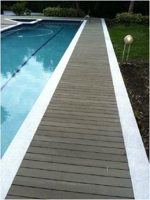
19 5.12 Result After cutting and installation of the end cap on the two profiles can be click-assembled. With this step the installation process is finished. How to clean the Esthec Terrace and protect it properly is described in the next chapter. Figure 31 Esthec Terrace Figure 32 Result Esthec Terrace 18

20 6. Cleaning protocol Once the Esthec Terrace has been installed we recommend you follow the steps below to ensure a well-protected terrace that is easy to clean. By following these instructions and using the Esthec cleaning products you can rest assured that your terrace will continue to look like new for many years. 6.1 Esthec Green Cleaner Figure 34 Esthec cleaning products A. Start by thoroughly cleaning the Esthec Terrace two or three times with water. It is advised to dilute Esthec Green Cleaner (preferably 1 part Cleaner to 10 parts water) and use only a hard brush. This will create a very thin layer of Esthec Green Cleaner, which will help protect the terrace from staining. B. If necessary a high-pressure-cleaner may be applied before executing step A. It is critical to keep a minimum distance of cm between the nozzle of the high-pressure-cleaner and the terrace at all times. C. Use water and a hard brush for basic cleaning. D. Use hot water, undiluted Esthec Green Cleaner and a hard brush to clean stained areas or heavily trafficked parts of the terrace. Most staining may be removed this way. Rinse well with water to avoid colour variations. E. Even though a Esthec Terrace is extremely stain resistant, we recommend removing any spillage immediately and spot cleaning the area with hot water, Esthec Green Cleaner and a hard brush to prevent permanent stains. F. If you have stubborn stains which cannot be removed by using the Esthec Green Cleaner or with a high-pressure-cleaner, you may wish to sand the Esthec Terrace profile syrface. Use grain 24. Sanding with minimum pressure, in the length direction of the terrace profile. N.B. Using undiluted Esthec Green Cleaner to clean the entire Esthec terrace is not recommended. In combination with high temperatures, Esthec Green Cleaner can affect sensitive types of varnish. Undiluted Esthec Green Cleaner should only be used on badly stained areas. After cleaning, these areas must be thoroughly rinsed with water. 19


21 6.2 Esthec Nano Sealer After cleaning, the Esthec Terrace it is advisable to treat the clean Esthec Terrace with Esthec Nano Sealer. Esthec Nano Sealer provides a strong protective layer against dirt and spillages and the terrace will be easier to keep clean. A. Apply Esthec Nano Sealer to a clean and dry surface. B. Repeat the treatment three to four times. The Esthec Terrace may appear darker after drying. C. Allow the Esthec Terrace to dry for 20 hours and then rinse it with water. Ensure the terrace can dry out evenly. Once fully dry the Esthec Terrace will return to its original colour. Figure 33 From left to right: Green Cleaner undiluted, 1 part Cleaner to 5 parts water, 1 part Cleaner to 10 parts water The use of Esthec Nano Sealer results in a dirt-repellent surface and prevents water stains. It is essential, however, to thoroughly rinse the Esthec Terrace with water to restore and maintain its original colour. Figure 34 Surface after rinsing and drying When more than 1 layer of Nano Sealer will be applied, please note that it is absolutely essential that the different layers of Nano sealer must be installed wet-in-wet. 20
22
Fortress Fe Posts must always be secured to the deck framing. Fortress Fe Posts should never be attached to only the deck boards.
 Installation Instructions for Fortress Horizontal Cable Panel System with UB-05 Brackets and Fe Posts It is the responsibility of the installer to meet all code and safety requirements, and to obtain all
METHOD STATEMENT. Sika FloorJoint S
 METHOD STATEMENT Table of Contents 1 SCOPE 3 2 PRODUCT 3 2.1 3 3 SUBSTRATE REQUIREMENTS 3 4 Preparation of the Substrate 3 4.1 Mapping of the joint panels on the floor for the saw cuts 3 4.2 Execution
I N S TA L L AT I O N & M A I N T E N A N C E G U I D E
 I N S TA L L AT I O N & M A I N T E N A N C E G U I D E E N V I R O B U I L D. C O M + 4 4 ( 0 ) 2 0 8 0 8 8 4 8 8 8 Version 3.2 EnviroBuild 2018 C O N T E N T S Storage & Handling 03 Tools 04 Calculating
Installation Operation Care. Sonnette Cellular Roller Shades. LiteRise Operating System
 Installation Operation Care Sonnette Cellular Roller Shades LiteRise Operating System CONTENTS GETTING STARTED: Product View...1 Tools and Fasteners Needed...2 INSTALLATION: Installation Overview...3 Mount
INSTALLATION GUIDE DUOFUSE SLAT WALL SYSTEM
 06/2013 ENG 1 INSTALLATION GUIDE DUOFUSE SLAT WALL SYSTEM The Duofuse wood composite slat wall system is much more durable than wooden fences, and correct installation is necessary to enjoy the fences
Fortress Fe Posts must always be secured to the deck framing. Fortress Fe Posts should never be attached to only the deck boards.
 Installation Instructions for Fortress Vertical Cable Panel System with Brackets and Fe Posts It is the responsibility of the installer to meet all code and safety requirements, and to obtain all required
PolyCarb has good resistance to many chemicals. Some chemicals may harm the PolyCarb sheets. Contact us when in doubt about any chemical.
 Polycarbonate Panels This manual provides the basic information for working with and installing PolyCarb sheets. Due to their hollow core, prior preparation is needed before the actual installation, with
Basic Assembly For Conventional Series 9000 Structural Panels
 Steelcase, Inc. Grand Rapids, MI 49501 U.S.A. 1-888-783-3522 Basic Assembly For Conventional Series 9000 Structural Panels NOTE: Assembly directions for curved panels are the same as standard panels. Tools
Retrofit Apron Front Farm Sink With Dual Mount Capability Installation Instructions
 For Under-Mount Installation please refer to page 14 FOR EXPERIENCED AND PROFESSIONAL INSTALLATION ONLY This installation project is designed for an advanced skill level. Disclaimer: Undermount Application
Fortress Fe Posts must always be secured to the deck framing. Fortress Fe Posts should never be attached to only the deck boards.
 Installation Instructions for FortressCable H-Series Cable Panel System With UB-05 Brackets and Fe Posts It is the responsibility of the installer to meet all code and safety requirements, and to obtain
SHIPLOCK CLADDING PRODUCT GUIDE INSTALLATION TECHNICAL SPECIFICATIONS CARE & MAINTENANCE
 SHIPLOCK CLADDING PRODUCT GUIDE INSTALLATION TECHNICAL SPECIFICATIONS CARE & MAINTENANCE SHIPLOCK CLADDING CN-04E / CN-04W / CN-W008 Prior to the installation of any form of Cladding, it is recommended
Robert Bosch GmbH. Lounge light fixture
 Lounge light fixture Nice and relaxing Lounge light fixture Light has an important effect on mood. This cool light fixture is perfect for creating a cosy lounge atmosphere. 1 Introduction This cool light
DeckRail A Product of DeckRite LLC 3912 East Progress North Little Rock, AR Phone: (501) Fax: (501)
 Fax: (501)") Disclaimer: Deck Rail Glass Railing Installation Guide This guide is not intended to replace a trained professional installer. The drawings and instructions contained within are for demonstration purposes
Disclaimer: Deck Rail Glass Railing Installation Guide This guide is not intended to replace a trained professional installer. The drawings and instructions contained within are for demonstration purposes
Laying and maintenance of cement tiles
 Laying and maintenance of cement tiles David&Goliath cement tiles are manufactured under licence in the Far East, according to our standards and specifications concerning colour and dimensional stability;
Installation Guide. Capped Cellular PVC Fencing. Table of Contents. Storage and Handling Tools Needed Fence Layout and Locating Posts
 Capped Cellular PVC Fencing Installation Guide Table of Contents Storage and Handling Tools Needed Fence Layout and Locating Posts Installation instructions 4 x 4 Over Sleeve Post - 3.5 Rail Privacy Shadowbox
Ambient Light Rejecting Fixed Frame Screen. (3.9 width frame) User s Guide
 User s Guide") Ambient Light Rejecting Fixed Frame Screen (3.9 width frame) User s Guide Attention: The DarkStar 9 is composed of high quality sensitive multi-layer projection material. Please follow the precautions
Ambient Light Rejecting Fixed Frame Screen (3.9 width frame) User s Guide Attention: The DarkStar 9 is composed of high quality sensitive multi-layer projection material. Please follow the precautions
15mm Solid European Droploc Oak Fitting Guide & Warranty Information
 15mm Solid European Droploc Oak & Warranty Information Introduction Congratulations on your purchase of your brand new Timba Floor 15mm European Solid Oak Flooring. Prior to installation please examine
CAVALIER. Shower Door Installation Instructions
 CAVALIER Shower Door Installation Instructions IMPORTANT DreamLine reserves the right to alter, modify or redesign products at any time without prior notice. For the latest up-to-date technical drawings,
ESSENCE - H SHOWER / TUB DOOR INSTALLATION INSTRUCTIONS
 ESSENCE - H SHOWER / TUB DOOR INSTALLATION INSTRUCTIONS IMPORTANT DreamLine reserves the right to alter, modify or redesign products at any time without prior notice. For the latest up-to-date technical
SHADOWBOX INSTALLATION FOR: Standard 6 H x 8 W Shadowbox Fence 5 x 5 Routed Posts Dog Ear or Straight-Edge Pickets 1.75 x 3.5 Rail
 SHADOWBOX INSTALLATION FOR: Standard 6 H x 8 W Shadowbox Fence 5 x 5 Routed Posts Dog Ear or Straight-Edge Pickets 1.75 x 3.5 Rail Storage and Handling Fence Preparation and Layout Locate and Set Posts
ATLANTIS RAIL Contact Information
 ATLANTIS RAIL Contact Information Customer Service (800) 541-6829 (508) 732-9191 Spectrum System Installation Instructions Atlantis Rail s Spectrum System is an easy to install, universal cable railing
IMPORTANT!!! ASSEMBLY ASSEMBLY INSTRUCTIONS. (Internal Dimensions)
") ASSEMBLY ASSEMBLY INSTRUCTIONS (Internal Dimensions) Ent Spec Edition Ltr v-0- Overall dimensions including base: 7. L x 9 W x 0 H cms 97.5" L x 7" W x 8.7" H IMPORTANT!!! Please read these instructions
ASSEMBLY ASSEMBLY INSTRUCTIONS (Internal Dimensions) Ent Spec Edition Ltr v-0- Overall dimensions including base: 7. L x 9 W x 0 H cms 97.5" L x 7" W x 8.7" H IMPORTANT!!! Please read these instructions
EASY APPLICATION. Furniture Linoleum
 EASY APPLICATION Furniture Linoleum can be applied easily on all common materials such as MDF, chipboard and Plywood as well as steel or composite materials. Furniture Linoleum has a special matte appearance
index READ CAREFULLY BEFORE STARTING THE INSTALLATION
 EasyChange system index READ CAREFULLY BEFORE STARTING THE INSTALLATION Components Tools you might need Before the installation dos and donts Preliminary evaluations EasyChange Rail Fixing the rails Rails
assembly guide Sliding Track Assembly Guidance Manual & Technical Data Sheets Issue ML/02 SEPTEMBER 2007
 Issue ML/02 SEPTEMBER 2007 assembly guide Sliding Track Assembly Guidance Manual & Technical Data Sheets Savekers Limited 101 Aldridge Road, Perry Barr, Birmingham, B42 2TS t f e w 0121 331 1903 0121 331
DULUX WOODGARD EXTERIOR TIMBAPRESERVATIVE
 TECHNICAL DATA SHEET Version 1 2015 SEPTEMBER THIS ISSUE SUPERSEDES ALL PREVIOUS PUBLICATIONS PRODUCT DESCRIPTION Deep penetrating wood treatment for exterior wood. PRODUCT USES A penetrating wood dressing
Maintenance and other important non-personal injury and non-material damage instructions or statements that should be observed.
 VIGO INDUSTRIES INSTALLATION GUIDE FOR SHOWER ENCLOSURE ()! SAFETY PRECAUTIONS This Installation Guide uses the following symbols to indicate important information. Always observe the instructions indicated
ESSENCE. Shower / Tub Door Installaion Instructions
 ESSENCE Shower / Tub Door Installaion Instructions IMPORTANT DreamLine reserves the right to alter, modify or redesign products at any time without prior notice. For the latest up-to-date technical drawings,
Installation Instructions for. Before You Begin TOOLS REQUIRED
 Composite Railing System STEP-BY-STEP Installation Instructions for Spectrum Composite Railing Virtually maintenance free 20-year warranty EverNew Spectrum Railing system is designed to work with a number
PRIVACY INSTALLATION FOR: Standard 6 H x 8 W Privacy Fence 4 x 4 Post Sleeve & Brackets Dog Ear or Straight-Edge Pickets 1.75 x 3.
 PRIVACY INSTALLATION FOR: Standard 6 H x 8 W Privacy Fence 4 x 4 Post Sleeve & Brackets Dog Ear or Straight-Edge Pickets 1.75 x 3.5 Rail Storage and Handling Fence Preparation and Layout Locate and Set
Fortress Al HOME posts must always be secured to the deck framing. Fortress Al HOME posts should never be attached to only the deck boards.
 Installation Instructions for Fortress Al HOME Traditional Adjustable Panels with Simplified and Al HOME Posts It is the responsibility of the installer to meet all code and safety requirements, and to
Arla WOODEN CARE GUIDE BY DIRECT OUTDOOR LIVING
 Arla WOODEN GUIDE BY DIRECT OUTDOOR LIVING This care guide will guide you on how to get the best from your Direct Outdoor Living garden furniture. Acacia Care The Acacia used in our products is highly
TREX TRANSCEND RAILING
 RAILING NOTES:» RAILINGS ARE DESIGNED TO BE INSTALLED OVER THE DECKING FRAME OR ON INSIDE OF RIM JOIST. NOTCHING OF PRESSURE-TREATED POSTS OR POSTS INSTALLED ON OUTSIDE OF RIM JOIST IS NOT ALLOWED.» All
Aerospace Speciality Products
 Specifications:! Length: 18.75"/47.6 cm! Diameter: 0.98"/24.9 mm! Weight: 1.5 oz/44 gm! Streamer Recovery! Recommended Engines:!! A8-3; B4-4; B6-4; C6-5! Skill Level: Beginner This is a model rocket kit
Your Performance Partner
 Assembly Instructions Attic Storage System Your Performance Partner CONTENTS Safety Precautions.................................. 2 Warranty.......................................... 2 Important User Information............................
PRIME SHOWER ENCLOSURE INSTALLATION INSTRUCTIONS
 PRIME SHOWER ENCLOSURE INSTALLATION INSTRUCTIONS IMPORTANT DreamLine reserves the right to alter, modify or redesign products at any time without prior notice. For the latest up-to-date technical drawings,
3Insert the second rod no. 4
 Yamato: Step-by-step 37 The stern block and searchlight control towers a b c d e f Recommended tools and materials Wood glue Sandpaper (no. 800 grain) Metal file Putty Craft knife For metal: Super Glue
Gluing windows with SABA Glasstack 760
 Info sheet 208 Gluing windows with SABA Glasstack 760 Version 2008-05-08 EN, replaces all prior versions Page 2 of 9 Info sheet 208 Gluing windows with SABA Glasstack 760, version 2008-05-08 EN 1. Introduction
Robert Bosch GmbH. Minimalist washstand
 Minimalist washstand Neat and tidy Minimalist washstand Minimalist design in the bathroom is in fashion. And rightly so, as this washstand proves: because less is more! 1 Introduction Here s an idea to
For best results, it is essential that you follow the installation instructions exactly.
 For best results, it is essential that you follow the installation instructions exactly. PREPRTION Let the planks acclimatize for 48 hours in the unopened packaging at the normal room temperature, in the
Elara NanoEdge Fixed Frame Screen User Guide
 Elara NanoEdge Fixed Frame Screen User Guide INTRODUCTION INTRODUCTION WARNING This product may contain sharp edges, please handle with care. Protective gloves are recommended. A minimum of two people
Cambridge International Examinations Cambridge International General Certificate of Secondary Education
 Cambridge International Examinations Cambridge International General Certificate of Secondary Education *2410250691* DESIGN AND TECHNOLOGY 0445/32 Paper 3 Resistant Materials May/June 2018 1 hour Candidates
Assembly instructions
 Assembly instructions SF 55 / SF 55c SF 75 / SF 75c / SF 75H A B B C D Scope of delivery: Safety instructions: A. Top rail B. Vertical profile C. Floor rail D. Hinged panel, sliding panel Accessories pack
ENIGMA AIR ENCLOSURE
 ENIGMA AIR ENCLOSURE SHOWER ENCLOSURE INSTALLATION INSTRUCTION IMPORTANT DreamLine reserves the right to alter, modify or redesign products at any time without prior notice. For the latest up-to-date technical
Installation Instructions and Details
 Installation Instructions and Details Contents Page General Notes 2 Typical System Perspective 3 Panel, Hardware & Trim Details 4-6 Hardware & Trim Fabrication Details 7-9 Installation Procedures 10-12
SURFACE PREPARATION AND MATERIAL APPLICATION KEIM MINERAL PAINTS
 SURFACE PREPARATION AND MATERIAL APPLICATION KEIM MINERAL PAINTS PRE-TREATMENT KEIM Mineral Paints are different to conventional film forming paints. Mineral paints are made with potassium silicate and
Install your floor between 18 and 30 C.
 GOLDEN RULES 8-0 C Install your floor between 8 and 0 C. Quick-Step Livyn must be acclimatized in the room of installation between 8-0 C for a period of at least 8 hours before installation. This floor
Installation Guide. Resysta Flooring. 15 Years Guarantee. swell-free crack-free splinter-free rot-free. Version 1 / July 2010 / English.
 Installation Guide Flooring 15 Years Guarantee swell-free crack-free splinter-free rot-free Flooring Version 1 / July 2010 / English 1 The Latest Test Result Classification C, DIN 51097: offers best skid-resistance
Installation of HORIZONT and HORIZONT HIGH pool enclosures
 Installation of HORIZONT and HORIZONT HIGH pool enclosures Rev. 19.10.2017 PARTS LIST Parts for rail installation: Rail screw 6 x 60 Plastic anchor 10 x 50 Rail connector Arrest wedge [R-L] Pop rivet 4
2017 UPDATED INSTALLATION INSTRUCTIONS
 2017 UPDATED INSTALLATION INSTRUCTIONS with square composite or round metal balusters Manufactured by fiberondecking.com 800.573.8841 Horizon Railing 6 ft. and 8 ft. Installation Instructions Required
1. TOOLS + MATERIALS REQUIRED
 R INSTALLATION INSTRUCTIONS PRODUCT: BALDUR + ODEN CONFIGURATION: BI-PARTING DOOR MOUNT: TOP MOUNT Product is covered by U.S. patents. For more information visit www.krownlab.com. TOOLS + MATERIALS REQUIRED
*** All chrome surfaces should be cleaned using a clean damp cloth. *** No abrasive cleaning agents or materials should be used.
 Cleaning *** All chrome surfaces should be cleaned using a clean damp cloth. *** No abrasive cleaning agents or materials should be used. *** No chemical cleaners can be used on the glass use only mild
Installation Operation Care
 Installation Operation Care Applause Honeycomb Shades LiteRise Operating System Contents GETTING STARTED Product View...1 Tools and Fasteners Needed...2 INSTALLATION Installation Overview...3 Mount the
PVC Composite Railing & Stair Kit
 FREEDOM-WEB PVC Composite Railing & Stair Kit INSTALLATION INSTRUCTIONS Read all instructions prior to installing product. Refer to manufacturers safety instructions when operating any tools. To register
INSTALLATION GUIDE DECKING.
 INSTALLATION GUIDE DECKING www.ttp-online.de/resysta CONTENT LATEST TEST RESULT Classification C, DIN 51097: Features, made by, best skid-resistance properties and is eminently suitable for wet barefoot
INSTALLATION AND CARE INSTRUCTIONS
 INSTALLATION AND CARE INSTRUCTIONS Vertical Applications Honeycomb Shades 52 C8-10-3401 Rev 2/14 CONTENTS Introduction...2 Before You Begin...3 Vertical Application Parts Overview...4 Materials Required...5
PRODUCT: LOKI INSTALLATION INSTRUCTIONS. Product is covered by U.S. patents. For more information visit
 R INSTALLATION INSTRUCTIONS PRODUCT: LOKI CONFIGURATION: SINGLE DOOR MOUNT: GLASS MOUNT Product is covered by U.S. patents. For more information visit www.krownlab.com . TOOLS + MATERIALS REQUIRED TOOLS
COFFEE TABLE WITH RECESSED TRAY
 COFFEE TABLE WITH RECESSED TRAY Why not treat your guests to a tray laid with delicacies and then remove it from sight in your new coffee table. There's no easier way to show that you are a thoughtful
Thank you for your order
 Installation Guide Thank you for your order Ph: 09-9133110 Fax: 09-9133113 5 Smales Road. East Tamaki, Manukau PO Box 58031 Greenmount, Manukau 2013 AUCKLAND // WELLINGTON // CHRISTCHURCH www.bathroomdirect.co.nz
HOW TO INSTALL ELITE PANELED WAINSCOTING Using X-Rails with Either Raised, Flat or Beaded Panels
 HOW TO INSTALL ELITE PANELED WAINSCOTING Using X-Rails with Either Raised, Flat or Beaded Panels 1. First, remove the cover plates from all electrical outlets. All baseboards should also be removed; the
Installation Guide (888)
") BamDeck Installation Guide (888) 788-2254 The Collection Decking Systems BAMDECK 4G 5-7/16 Wide Plank Dims: 192 L x 5-7/16 W x 13/16 H BAMDECK 4G WIDE 8-1/4 Wide Plank Dims: 96 L x 8-1/4 W x 13/16 H BAMDECK
BamDeck Installation Guide (888) 788-2254 The Collection Decking Systems BAMDECK 4G 5-7/16 Wide Plank Dims: 192 L x 5-7/16 W x 13/16 H BAMDECK 4G WIDE 8-1/4 Wide Plank Dims: 96 L x 8-1/4 W x 13/16 H BAMDECK
Vertical Honeycomb Shades
 Step by Step Installation Instructions Vertical Honeycomb Shades Customer Service 800.248.8888 or visit us online at smithandnoble.com Thank you for purchasing from Smith+Noble. Your new shades have been
Installation And Care Instructions. Vertical Honeycomb Shades
 Installation And Care Instructions Vertical Honeycomb Shades Rev 5/2013 Table Of Contents Getting Started... 3 Parts Overview... 4 Materials Required... 5 Tools Required... 6 Outside Mount Installation...
HOW TO INSTALL HORIZONTAL ROD RAILING TREX SIGNATURE STANDARD
 HOW TO INSTALL HORIZONTAL ROD RAILING NOTES:» Adjust drill power to lowest setting that will drive screw. DO NOT OVER TORQUE 6 STAINLESS STEEL STAINLESS FASTENERS.» NEVER use impact tools on 6 Stainless
INSTALLATION AND CARE INSTRUCTIONS
 INSTALLATION AND CARE INSTRUCTIONS Vertical Applications Honeycomb Shades CONTENTS Introduction...2 Before You Begin...3 Vertical Application Parts Overview...4 Materials Required...5 Tools Required...6
HAND HELD SAW W MILL
 HAND HELD SAW W MILL 92247 ASSEMBLY AND OPERATING INSTRUCTIONS 3491 Mission Oaks Blvd., Camarillo, CA 93011 Visit our Web site at http://www.harborfreight.com Copyright 2004 by Harbor Freight Tools. All
FLEX 28 / 32 / 42 x 72
 FLEX 28 / 32 / 42 x 72 SHOWER DOOR INSTALLATION INSTRUCTIONS IMPORTANT DreamLine reserves the right to alter, modify or redesign products at any time without prior notice. For the latest up-to-date technical
HALLMARK DECKING INSTALLATION MANUAL
 HALLMARK DECKING INSTALLATION MANUAL CARE AND MAINTENANCE Congratulations on the purchase of your Hallmark composite decking. To ensure that you keep your low maintenance decking looking its best we recommend
Safety First! Use eye protection, always! Use ear protection with loud power tools. Stay with children while they work!
 TM TM ART TABLE Safety First! Use eye protection, always! Use ear protection with loud power tools Stay with children while they work! Follow tool manufacturers safety guidelines Page 1 ART TABLE Page
EZYSTONE WORKSURFACES
 EZYSTONE WORKSURFACES Installation & Maintenance Instructions 1. Tools Required Worktop Edge Finishing Kit Pack 1-100mm Velcro Backing Pad Pack 2-100mm Diamond Dry Cut Velcro Discs (100 Grit Yellow) (200
FUSION JULIETTE BALCONIES FITTING INSTRUCTIONS
 FUSION JULIETTE BALCONIES FITTING INSTRUCTIONS The Richard Burbidge FUSION Juliette Balcony System comprises a combination of timber and aluminium rails, glass infill panels and brackets designed for use
INSTALLATION INSTRUCTIONS FOR REPLACEMENT FORGENT WOOD GLASTRA WINDOWS RECOMMENDATIONS FOR COMMON INSTALLATION OF ALL REPLACEMENT WINDOWS.
 INSTALLATION INSTRUCTIONS FOR REPLACEMENT FORGENT WOOD GLASTRA WINDOWS RECOMMENDATIONS FOR COMMON INSTALLATION OF ALL REPLACEMENT WINDOWS. Installer: DO NOT DISCARD Please leave the Installation Guide
Installation Instructions For Custom Roman Shades
 Roman Shade Installation Guide Installation Instructions For Custom Roman Shades Step 1. Check Package Contents Missing part? Call 800-264-1190 Mounting hardware kit includes the following: Part Quantity
VITREO X SHOWER / TUB DOOR INSTALLATION INSTRUCTIONS
 VITREO X SHOWER / TUB DOOR INSTALLATION INSTRUCTIONS IMPORTANT DreamLine reserves the right to alter, modify or redesign products at any time without prior notice. For the latest up-to-date technical drawings,
Sabre Series 2 Inspired Design Precision Engineering
 Sabre Series 2 Inspired Design Precision Engineering USER INSTRUCTIONS Thank you for choosing the Keencut Sabre Series 2. Every effort has been made to bring you a precision engineered product with the
Fortress Fe Posts must always be secured to the deck framing. Fortress Fe Posts should never be attached to only the deck boards.
 Installation Instructions for FortressCable H-Series Stair Panels with Simplified Stair Bracket SSB-05 and Fe Posts It is the responsibility of the installer to meet all code and safety requirements, and
terraza and structura Installation Instructions. Privacy Shield Systems
 terraza and structura Installation Instructions. Privacy Shield Systems No warranty or approval in case of non-compliance Up-to-date installation instructions and drawings: www.werzalit.com Version 04
3Position the hull of the ship as
 Yamato: Step-by-step 25 The hull and stern deck c b d a b d c e e f a Rear frame b Stern deck x 2 c Stern deck x 2 d Side wall x 2 Wood glue Sandpaper (no. 400 grain) Craft knife Pliers d Side wall x 2
The following instructions will guide you through the installation of your new vinyl railing.
 Installation Guide St. James Vinyl T-Rail Tools Required Protective eye glasses 3/8 x 3 Concrete Anchors/Fasteners (for Tape measure concrete installations) Variable speed drill/screwdriver Philips Driver
ROLLER STAND WITH TWO-LEG SUPPORT ASSEMBLY AND OPERATING INSTRUCTIONS
 ROLLER STAND WITH TWO-LEG SUPPORT 95621 ASSEMBLY AND OPERATING INSTRUCTIONS 3491 Mission Oaks Blvd., Camarillo, CA 93011 Visit our Web site at http://www.harborfreight.com Copyright 2006 by Harbor Freight
Guard Rail with In-Fill Panel
 Assembly Instructions Guard Rail for Wenger Versalite TM TM, Trouper, Stagehand, Portamaster, Showmaker Platform Systems Guard Rail with In-Fill Panel CONTENTS Important User Information...........................................................................
Bird Feeder BUILD TIME
 This bird feeder should attract many different birds to your yard. With a platform for those birds that like to move around on a flat surface while they pick at feed as well as a dowel for those who prefer
HOW TO INSTALL HORIZONTAL ROD RAILING TREX SIGNATURE STANDARD
 HOW TO INSTALL HORIZONTAL ROD RAILING NOTES:» Adjust drill power to lowest setting that will drive screw. DO NOT OVER TORQUE 36 STAINLESS STEEL STAINLESS FASTENERS.» NEVER use impact tools on 36 Stainless
DULUX UNIVERSAL UNDERCOAT
 TECHNICAL DATA SHEET Version 1 2015 JUNE THIS ISSUE SUPERSEDES ALL PREVIOUS PUBLICATIONS PRODUCT DESCRIPTION Intermediate coating for use under decorative topcoats, for interior and exterior use PRODUCT
Composition of kit SC3140 SC3110 SC3100 SC3140 SC3120. KF-SC31-R0_EN PAGE 2 of 15. max mm. max. 100 kg. 10 mm
 Composition of kit SC3140 SC3100 SC3140 SC3120 max. 100 kg 10 mm max. 2700 mm KF-SC31-R0_EN PAGE 2 of 15 important information KF-SC31-R0_EN PAGE 3 of 15 DIAGRAM OF WALL OPENING AND CROSS-SECTION Lv LG
INFINITE RANGE - CENTRE FOLDING DOOR
 INFINITE RANGE - CENTRE FOLDING DOOR CENTRE FOLDING DOOR ONLY ( RECESS) Please read these instructions before installing, as incorrect fitting will invalidate the guarantee-carry out each stage before
15 Dovetail Jig. Instruction Manual. Part # 3452
 15 Dovetail Jig Instruction Manual Part # 3452 CAUTION: Please read, understand, and follow all manufacturers instructions, guidelines and owners manuals that come with your power tools. Peachtree Woodworking
PARAGON BATH SHOWER DOOR/ BATH TUB SCREEN INSTALLATION INSTRUCTIONS. DR-584b
 PARAGON BATH SHOWER DOOR/ BATH TUB SCREEN INSTALLATION INSTRUCTIONS DR-584b Please read these instructions carefully before installing. If you have any questions regarding installation, please call our
INFINITY-Z SHOWER DOOR / TUB DOOR INSTALLATION INSTRUCTION. MODEL #s 01-Chrome
 INFINITY-Z SHOWER DOOR / TUB DOOR INSTALLATION INSTRUCTION IMPORTANT DreamLine reserves the right to alter, modify or redesign products at any time without prior notice. For the latest up-to-date technical
UNIDOOR-X TUB DOOR TUB DOOR INSTALLATION NSTRUCTIONS. MODEL #s D58580-##
 T F UNIDOOR-X TUB DOOR se A R a e l re TUB DOOR INSTALLATION I NSTRUCTIONS r o D ved f IMPORTANT DreamLine reserves the right to alter, modify or redesign products at any time without prior notice. For
INSTALLATION INSTRUCTIONS PRAVOL DURA-SHIELD COMPOSITE DECK RAILINGS
 INSTALLATION INSTRUCTIONS PRAVOL DURA-SHIELD COMPOSITE DECK RAILINGS Important: Read all sections before you start Prior to installing railing, please consult local zoning laws in regards to load requirements
T r e x Art i s a n Se r i e s Railing
 T r e x Art i s a n Se r i e s Railing I n s t a l l a t i o n In s t ru c t i o n s Trex Railing Components A. Trex Top Rail B. Trex Bottom Rail C. Trex Railing Support Bracket D. TrexExpress Railing
Coffee table with recessed tray
 Coffee table with recessed tray Dinner is served Coffee table with recessed tray This coffee table has it all: it contains a recessed tray, so that you can treat your guests to various delicacies. 1 Introduction
IMPORTANT: Read all sections before you start
 1 IMPORTANT: Read all sections before you start For the most up to date information please visit our website @ www.newtechwood.com Prior to installing the railing, please consult local zoning laws in regards
Aeon CLR Series EDGE FREE CLR Fixed Frame Screen w/ StarBright CLR (Ceiling Light Rejecting ) Front Projection Material
 Front Projection Material") Aeon CLR Series EDGE FREE CLR Fixed Frame Screen w/ StarBright CLR (Ceiling Light Rejecting ) Front Projection Material User s Guide Product Description: The Aeon CLR Series is an ultra-short throw fixed
Aeon CLR Series EDGE FREE CLR Fixed Frame Screen w/ StarBright CLR (Ceiling Light Rejecting ) Front Projection Material User s Guide Product Description: The Aeon CLR Series is an ultra-short throw fixed
Installation Instructions
 Installation Instructions MAP (Mechanically Applied Panels) Please Read Disclaimers: PLEASE READ ALL INSTRUCTIONS BEFORE BEGINNING INSTALLATION These guidelines are provided in good faith to help prevent
Installation Operation Care
 Installation Operation Care Applause Honeycomb Shades LiteRise Operating System with TrimKit Contents GETTING STARTED Product View... 1 Tools and Fasteners Needed... 2 INSTALLATION Installation Overview...
INSTALLATION GUIDE SLIMLINE ROOF LANTERN 4 PANE CONFIGURATION
 INSTALLATION GUIDE SLIMLINE ROOF LANTERN 4 PANE CONFIGURATION SLIMLINE STEP-BY-STEP INSTALLATION GUIDE Thank you for choosing Roof Maker, we hope you are delighted with your new rooflight. Our roof lanterns
GREENHOUSE 6'x8' ASSEMBLY INSTRUCTIONS. (Internal Dimensions) Overall Dimensions (Approx.) L 193 W 200 H cms 97.5" L 76" W 78.
 Overall Dimensions (Approx.) L 193 W 200 H cms 97.5 L 76 W 78.") ASSEMBLY INSTRUCTIONS GREENHOUSE 'x8' (Internal Dimensions) Overall Dimensions (Approx.) 7. L 9 W 00 H cms 97." L 7" W 78.8" H 0 IMPORTANT You must read these instructions carefully before you start to
ASSEMBLY INSTRUCTIONS GREENHOUSE 'x8' (Internal Dimensions) Overall Dimensions (Approx.) 7. L 9 W 00 H cms 97." L 7" W 78.8" H 0 IMPORTANT You must read these instructions carefully before you start to
SlipGrip Data Sheet & Installation Guide
 SlipGrip Data Sheet & Installation Guide Stair Treads Landing Covers Flat Sheets 9/2015 SlipGrip Technical Data Description SlipGrip products are high performance safety stair treads, landing covers and