UDS OVERVIEW Uniform Drawing System
|
|
|
- Nathan Moore
- 5 years ago
- Views:
Transcription
1 UDS OVERVIEW Uniform Drawing System The Construction Specifications Institute 601 Madison Street Alexandria, VA 1994 CSI began development of UDS Organization and presentation of drawing sets Organization and presentation of Sheets, schedules, and diagrams Standards for drafting conventions and color Standard systems for keynotes, attributes, and CAD layering
2 UDS OVERVIEW 1995 UDS was accepted by: AIA Tri-Service CADD/GIS Technology Center US Coast Guard National Institute of Building Sciences UDS provides uniformity for graphical information in drawings Similar to MasterFormat, Section Format, and Page Format in specifications
3 UDS OVERVIEW Drawing Users: Owner Design Professionals Contractor Owner s Rep Consultant Subcontractor Material supplier Product Manufacturer Building Official Government Official Accountant Attorney Lender End user
4
5 UDS OVERVIEW Modules Drawing Set Organization For use by traditional architectural and engineering disciplines Establishes standard designators for disciplines and presentation order of disciplines in document set. Establishes consistency throughout set Accommodates both simple and complex projects Drawing Sheet Organization Standards for sheet sizes both metric and inch-pound systems Provides a grid system of blocks for organizing information Format for title block
6 UDS OVERVIEW Modules, Con t Schedules Consistent format, heading terminology, and content organization Groups and identifies schedule types based on MasterFormat Numbers Layering AIA, CAD layer Standards with updates from CSI Drafting Conventions Symbols, Material indications, line types, dimensions, drawing scale, diagrams, notation, terminology and abbreviations
7 UDS OVERVIEW Modules, Con t CAD Standards Reference files Presentation and model views Pen assignments Plotting guidelines Data exchange Color Standards for construction drawings
8 UDS OVERVIEW Drawings Plans Elevations Sections Large Scale Views Details Schedules Diagrams 3D Representations
9 Drawing Set Organization Set Content and Order Sheet Identification Discipline Designators Modifiers Sheet numbering sequence File Naming Project Flies specific drawings and sheets Library Files Generic and template files
10 Drawing Set Organization Set Content and Order Types of Construction Drawings Bidding Drawings Issued before signing of contract Contract Drawings Describe the work of the project Resource Drawings Shows existing conditions New construction not related to Contract
11 Drawing Set Organization Drawing Subsets/ Sheet Identification
12 Drawing Set Organization Discipline Designator 1 st Component - character(s) (1or2) Alphabetical (I) Levels One and Two Ex: Level 1 T (telecommunications) Level 2 TA (Telecommunications, audio visual) If second level is not required then use a dash (-)
13 Drawing Set Organization Discipline Designator Level 1 G - General Cover Sheet Index Sheet H - Hazardous Materials C - Civil L - Landscape S - Structural A Architectural Level 2: AS Architectural site AD Architectural Demolition AE Architectural Elements AI Architectural Interiors AF Architectural Finishes AG Architectural Graphics
14 Drawing Set Organization Discipline Designator s Con t Level 1 I Interiors Level 2: ID Interior Demolition IN Interior Design IF Interior Furnishings IG Interior Graphics
15 Drawing Set Organization Discipline Designators, Con t Level 1 Q - Equipment F - Fire Protection P - Plumbing M - Mechanical E - Electrical T - Telecommunications R Resource X Other Disciplines Z Contractor/Shop Drawings

16 Drawing Set Organization Sheet Type Designator 2 nd Component Numerical (I-1) 0 General 1 Plans 2 Elevations 3 Sections 4 Large Scale Views 5 Details 6 Schedules and Diagrams 7 User Defined 8 User Defined 9 3D Representations Remember, sheet type designators do not preclude combining different types of drawings Ex: Place schedules on a sheet when the information is closely associated
17 Drawing Set Organization Sheet Sequence Designator 3rd Component a two-character number. Ex: 01, 02, 03 (I-101)
18 Supplemental Drawings Drawing Set Organization If revisions are extensive (revision cloud not feasible) the a new sheet must be altered. A user defined suffix would the be used R Revised smaller scope X Complete changes Ex: (I-101R1)
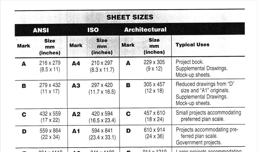
19 Drawing Set Organization File Naming Consistent file naming and folder structures are necessary for management of information that is reusable from project to project Categories Library Files Project Files
20 Drawing Set Organization Library Files The library file would be copied to the drawing and assigned a file name appropriate to the project.: Details Schedules Text Database Symbols Borders Titleblock Etc.
21 Drawing Set Organization Project Files Specific to a project Types: Model Files Electronic representation of a building Ex: (I-FP0000.dwg) 0, user defined modifier FP Floor Plan SP Site Plan DP Demolition Plan QP Equipment Plan XP Existing Plan EL Elevation SC Section DT Detail SH Schedules 3D DG - Diagrams
22 Types: Drawing Set Organization Project Files Detail Files A specific type of model file. Detail indicator represents its position on the drawing detail sheet Ex: (I-501-B3.dwg) Sheet position system will be discussed later Sheet Files Name should be consistent with the sheet identification category of the physical drawing. Schedule Files Often produced by software other than CAD If CAD software is used the schedule should be created full size Designate similar to the Detail file indicating the position on the drawing sheet Ex: (I-601-D1)
23 Drawing Set Organization Project Files Types: Text Files Usable from one project to another General Notes Discipline specific Notes Symbol Legends This is a library file Once imbedded in a drawing a new file name is not needed Database Files Examples Any schedule Inventory listings Master Keynotes So, this depends on the linkage of the file.
24 Drawing Set Organization File Management Project Folders Simplifies back and archival tasks Examples 1PREDES Programming and Pre-design phase 2SCHEM Schematic Design and Concept 3DESDEV Design Development 4CONDOC Construction Document 5CONTRAC Contract Submittal 6RECORD Record Document Phase 7FACMAN Facility Management Phase
25 Drawing Sheet Organization Benefits of Sheet Organization Provides a consistent sheet format Provides location system for drawings on sheet Enhanced communication among drawing preparers and users Improved quality control less risk of error Easier data management Coordinated images among disciplines
26 Drawing Sheet Organization Sheet Sizes The most important determinant is selecting a size that will allow placing the floor plan on a single sheet When plans are divided, a key plan on each plan sheet is necessary to indicate sector Architectural A 9x12 Project book, supplemental drawings, Mock-up sheets B 12x18 Reduced drawings from D size, Mock-up sheets C 18x24 Small Projects accommodating preferred plan scale D 24x36 Projects accommodating preferred scale, Government projects E 36x48 Accommodating preferred scale, Mapping and GIS F 30x42 Accommodating preferred scale
27
28 Drawing Sheet Organization Sheet Layout Drawing Area Title Block Area Minimum Sheet Margins: Top and bottom 3/4 Left Margin 1-1/2 Right Margin 3/4
29 Drawing Sheet Organization Drawing Area Divided into modules Module size (approx) 5-3/4 high x 6 wide Drawing Area Coordinate System Columns left to right 1, 2, 3, 4,. Rows Bottom to top A, B, C, D,. The drawing is identified based on the lower left hand location Preferred that coordinates are placed on all four sides and outside drawing area depends on plotting hardware Minimum place coordinates on right hand side and top or bottom Note Block (More on this later) Keynotes, general notes, and key plans most Right-hand column Key plan is located in the lowest module of the right column
30
31 Drawing Sheet Organization Title Block Area Designer Identification Block Project Identification Block Issue Block Management Block Sheet Title Block Sheet Identification Block
32 Drawing Sheet Organization Title Block Area Sheet Identification Block Optional data would be the sheet count and the total number of sheets (set or discipline)
33 Title Block Area Drawing Sheet Organization Sheet Title Block Type of information on sheet Sheet may contain one or more types of drawings notation usually refers to major drawing
34 Title Block Area Drawing Sheet Organization Management Block Drawing project number Owner s contract Number File Number Design Phase Number Drawn by: Checked by: Copyright

35 Title Block Area Drawing Sheet Organization Issue Block Phase issue dates Addendum issue dates Clarification dates Revision issue dates
36 Title Block Area Drawing Sheet Organization Project Identification Block Project name and address Building of facility name Construction phase sequence Project Logo Other client information address, phone, etc.
37 Title Block Area Drawing Sheet Organization Designer Identification Block Name Address Contact info Logo and professional seal Consultants
38 Title Block Area Drawing Sheet Organization Formats Horizontal Most commonly used preferred. Allows easier reading Vertical Sheet identification block is always horizontal
39 Cover Sheet Drawing Sheet Organization Unique Project Owner Photograph Rendering of project Logo If it contains project data then should have a sheet identifier G [Designator (G), Sheet type (0), Sequence number (01)] Table of contents Listing of Abbreviations General notes Building code survey Key plan Etc.
40 Drawing Sheet Organization Supplemental Drawing Sheets 9x12 or 12x18 Minimum margins ½ except for bound edge ¾
41
42 Notations Notes are part of the contract document Have important legal consequences Terms used in the notes must be consistent with the terms used in the specifications Early Twentieth Century Drawings were primarily graphic Notes were used sparingly affording the opportunity to provide additional information in the field (architect and engineer) Keying became a standard method for improving drawing clarity through reduction is the amount of text
43 Notations Types of Notes Five General Notes General Discipline Notes General Sheet Notes Reference Keynotes Sheet Keynotes
44 Notations General Notes Located in the General Drawings Sheet Types (G) Apply to the entire work Not necessary or desirable to repeat these notes on subsequent sheets
45 General Notes Notations
46 Notations General Discipline Notes Located on the first or O series sheets within a discipline Should not be repeated on other sheets of that discipline Instruction concerning discipline specific drafting conventions Coordinate with other project information General Architectural Notes General Structural Notes General Mechanical Notes General Interior Design Notes
47 Notations General Sheet Notes Sheet specific information or instructions Sequential order They Follow: General Notes General Discipline Notes They Precede Reference Keynotes Sheet Keynotes Ex: Dimensions on this sheet drawn to partition walls are to face of stud unless noted otherwise
48
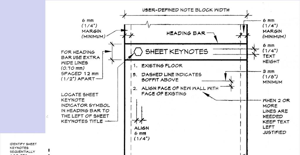
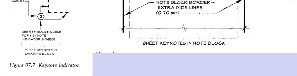
49 Notations Reference Keynotes Reference graphic representations to specific sections in the specifications Sheet Keynotes Specific notes related to graphic information on the sheet Drawn with a hexagonal symbol The bottom of the symbol should be drawn parallel to the bottom of the sheet Numerals are sequential They Follow sheet reference keynotes if used
50
51 Notations Note Block Hierarchy Position notes within the note Block as developed for the sheet Remember to leave space for sheet key plan if using General Notes are first in the note block If more than on column is needed, shift first column to the left and add another column
52
53
54
55 Notations Users guide Generic terminology should be based on well known, commonly available sources CSI Terms and abbreviations Module Drawing notes should match the terminology in the specifications It is not a good practice to repeat proprietary names, model numbers, and other detailed information within the drawing notes Fonts should be capitalized, proportional, san-serif, and non stylized. Do not use italics, underlining, bold Try to avoid abbreviations. If abbreviations are necessary, they should be coordinated throughout drawing If reference to a specification, then be specific
56
57
58
59
2 The UDS is a component of the United States National CAD
 Sheet Specifications By Ronald L. Geren, AIA, CSI, CCS, CCCA, SCIP Some projects are of such a small size that for a separate project manual containing the project specifications is considered unnecessary.
Section 4: Ontario Realty Corporation CAD Standards and Guidelines
 Section 4: Ontario Realty Corporation CAD Standards and Guidelines Ontario Realty Corporation 11 th Floor, Ferguson Block 77 Wellesley Street West Queen s Park Toronto, ON, M7A 2G3 August 10, 2007 Version
5.4 TECHNICAL REQUIREMENTS FOR DRAWINGS AND ELECTRONIC DOCUMENT SUBMISSIONS
 Chapter 5 Technical Documents 5.4 TECHNICAL REQUIREMENTS FOR DRAWINGS AND ELECTRONIC DOCUMENT SUBMISSIONS A. GENERAL 1. The need to exchange information during a projects life cycle with the State, Client
Bureau of Engineering. CADD Standards. Preface
 BOE CADD STANDARDS Preface The is committed to improving the quality of project delivery offered to all our Clients. By producing electronic design data consistently, communication among designer, owner
CHAPTER A-10 DRAWINGS
 CHAPTER A-10 DRAWINGS INDEX Revised May 2018 10.1 GENERAL 10.1.1 Purpose and Scope 10.2 APPLICABLE PUBLICATIONS 10.3 COMPUTER AIDED DESIGN (CAD) 10.3.1 CAD Requirements 10.3.2 CAD Deliverables 10.3.3 CAD
Architectural Floor Plan Symbols
 Architectural Floor Plan Symbols The symbols below are used in architectural floor plans. Every office has their own standard, but most symbols should be similar to those shown on this page. Building Section
The CAD Technician s Role in Office Practice and Procedure
 COMMERCIAL DRAFTING AND DETAILING 4TH EDITION JEFFERIS SOLUTIONS MANUAL Full download at: https://testbankreal.com/download/commercial-drafting-detailing-4th-editionjefferis-solutions-manual/ Chapter 2
Miami University. Physical Facilities Department. CAD Standards. April 2004
 Miami University Physical Facilities Department CAD Standards April 2004 1.0.0 OVERVIEW These standards pertain to the use, production and submittal of electronic CAD files at Miami University. They have
Dimension Below are the critical settings in AutoCAD. Other software should follow the same settings.
 8.1 Drawing Standard 8.1.1 Introduction This drawing standard applies to all building drawings being prepared for the University of Calgary (UCalgary) by external consultants or vendors and internal staff
AutoCAD Standards University of California, Santa Cruz Physical Planning & Construction
 University of California, Santa Cruz Physical Planning & Construction 1. General Requirements: 1.1 Format 1.2 Ownership 2. Required Data: 2.1 Area Tabulation 2.2 Drawing Files 2.3 External References 2.4
SECTION SUBMITTAL PROCEDURES PART 1 - GENERAL 1.1 RELATED DOCUMENTS
 SECTION 01 33 00 - SUBMITTAL PROCEDURES PART 1 - GENERAL 1.1 RELATED DOCUMENTS A. Drawings and general provisions of the Contract, including General and Supplementary Conditions and other Division 01 Specification
NORTHWESTERN UNIVERSITY PROJECT NAME JOB # ISSUED: 12/12/2018
 SECTION 01 7839 - PROJECT RECORD DOCUMENTS GENERAL 1.1 RELATED DOCUMENTS A. Drawings and general provisions of the Contract, including General and Supplementary Conditions and other Division 01 Specification
Vanderbilt University Standard Specification Revised 2/6/08
 SECTION 01 78 23 OPERATION AND MAINTENANCE DATA PART 1 GENERAL 1.01 RELATED SECTIONS A. Section 01 77 00 Closeout Procedures B. Section 01 78 39 Project Record Documents 1.02 SUMMARY A. This section provides
PITKIN COUNTY STANDARDS for ELECTRONIC DRAWINGS and DOCUMENTS SUBMISSION
 PITKIN COUNTY STANDARDS for ELECTRONIC DRAWINGS and DOCUMENTS SUBMISSION DOCUMENT SUBMISSION For Building Permit Submittal: Applicants bring Permit Application, Digital Drawings, and Supporting Documents
SECTION SUBMITTAL PROCEDURES
 SECTION 013300 PART 1 - GENERAL 1.1 RELATED DOCUMENTS A. Drawings and general provisions of the Contract, including General and Supplementary Conditions and other Division 01 Specification Sections, apply
1.1 The Electronic Word Programs used for the Project Manual shall be Microsoft Word.
 DESIGN REQUIREMENTS 1. CONTRACT DOCUMENT FORMAT: 1.1 The Electronic Word Programs used for the Project Manual shall be Microsoft Word. 1.2 The Electronic Drafting Program used for the Contract Drawings
RIT CAD Specifications
 RIT CAD Specifications The design team shall provide RIT with Revit, AutoCAD, and PDF files that capture the construction conditions of the associated project. This document outlines requirements for submitting
BIM Introduction. Building Information Management Definitions, Applications and general information. Betty Bezos
 BIM Introduction Building Information Management Definitions, Applications and general information Betty Bezos betty@bezos.com 9/1/2017 1 9/1/2017 2 Innovations in BIM 3D Design: 3D visualizations allow
LACCD CADD STANDARDS Revision 3.1
 LACCD CADD STANDARDS Revision 3.1 Prepared By: Revised June 2, 2010 Table of Contents 1 INTRODUCTION 1 1.1 LACCD Project CADD Standards 1 1.2 Revision History 1 1.3 Software Guidelines 1 2 DRAWING REQUIREMENTS
READING ARCHITECTURAL PLANS
 READING ARCHITECTURAL PLANS ARCHITECTURAL DRAWINGS FOR A HOUSE Architectural drawings contain information about the size, shape, and location of all parts of the house ARCHITECTURAL DRAWINGS FOR A HOUSE
ELECTRONIC DRAFTING GUIDELINES
 ELECTRONIC DRAFTING GUIDELINES Edition No. 6 Updated November 2016 TABLE OF CONTENTS Section Title Page 1 Definitions 3 2 Drawing Format 3 2.1 Standards & Guidelines 3 2.2 Survey Plans 4 2.3 Underground
CAD Standards for LAWA Projects. CAD Standards for LAWA projects
 CAD Standards for LAWA Projects CAD Standards for LAWA projects Document History revision letter release date major changes approved by A September 2012 new version of standards B June 2014 General Review
Making Standard Note Blocks and Placing the Bracket in a Drawing Border
 C h a p t e r 12 Making Standard Note Blocks and Placing the Bracket in a Drawing Border In this chapter, you will learn the following to World Class standards: Making standard mechanical notes Using the
This specification describes the minimum technical requirements for drawings, as applicable to all disciplines.
 SPEC-0800 1/5 1.0 PURPOSE This specification describes the minimum technical requirements for drawings, as applicable to all disciplines. 2.0 VALE DRAWING TYPE DEFINITIONS Engineering Drawings Engineering
Unit 1: Introduction to Drafting (Chapter1: World Wide Graphics)
") Unit 1: Introduction to Drafting (Chapter1: World Wide Graphics) DFTG-1305 Technical Drafting Instructor: Jimmy Nhan Giesecke, Hill, Spencer, Dygdon, Novak, Lockhart, Goodman 1 OBJECTIVES 1. Professions
Unit 1: Introduction to Drafting (Chapter1: World Wide Graphics) DFTG-1305 Technical Drafting Instructor: Jimmy Nhan Giesecke, Hill, Spencer, Dygdon, Novak, Lockhart, Goodman 1 OBJECTIVES 1. Professions
PORTAGE COUNTY WATER RESOURCES DRAFTING STANDARDS. Date: January 26, 2001
 PORTAGE COUNTY WATER RESOURCES DRAFTING STANDARDS Date: January 26, 2001 Portage County Water Resources Drafting Standards. AutoCad 2000/Land Development Desktop R2 Friday, January 26, 2001 Preface: Part
TCC/SHORE TRANSIT BUS MAINTENANCE FACILITY - PHASE II
 SECTION 013300 - SUBMITTAL PROCEDURES PART 1 - GENERAL 1.1 RELATED DOCUMENTS A. Drawings and general provisions of the Contract, including General and Supplementary Conditions and other Division 01 Specification
SECTION SUBMITTAL PROCEDURES
 SECTION 01330 - SUBMITTAL PROCEDURES PART 1 - GENERAL 1.1 RELATED DOCUMENTS A. Drawings and general provisions of the Contract, including General and Supplementary Conditions and other Division 1 Specification
NORTHWESTERN UNIVERSITY PROJECT NAME JOB # ISSUED: 03/29/2017
 SECTION 01 3300 - SUBMITTAL PROCEDURES PART 1 - GENERAL 1.1 RELATED DOCUMENTS A. Drawings and general provisions of the Contract, including General and Supplementary Conditions and other Division 01 Specification
LESSON 1: UNDERSTANDING CONSTRUCTION DRAWINGS
 LESSON 1: UNDERSTANDING CONSTRUCTION DRAWINGS INTRODUCTION In this lesson, you ll learn about the different types of drawings used in the construction industry, and how to read floor plans, section drawings,
FACILITIES CADD STANDARD
 2015 Facilities Services Division of Design and Construction CADD Department FACILITIES CADD STANDARD CAD, BIM, & GIS Standards for the University of Alaska Fairbanks The University of Alaska Fairbanks
A. Section includes administrative provisions for coordinating construction operations on Project including, but not limited to, the following:
 SECTION 01 31 00 PROJECT MANAGEMENT AND COORDINATION PART 1 GENERAL 1.1 RELATED DOCUMENTS A. Drawings and general provisions of the Contract, including General and Supplementary Conditions and other Division
Test Code: 8294 / Version 1
 Pennsylvania Customized Assessment Blueprint Test Code: 8294 / Version 1 Copyright 2014. All Rights Reserved. General Assessment Information Blueprint Contents General Assessment Information Written Assessment
BIM/VDC on TAA Projects:
 2018 Logan International Airport BIM/VDC on TAA Projects: Direct Tenant TAA Projects Third Party Development Properties Massachusetts Port Authority Capital Programs & Environmental Affairs Preface Massport
Chapter 7 Computer-Aided Design and Drafting in Architecture 2D vs. 3D 3 Advantages/ Disadvantages
 Chapter 7 Computer-Aided Design and Drafting in Architecture 2D vs. 3D 3 Advantages/ Disadvantages What is CADD or CAD CADD- CAD- BIM- What does BIM require? Intro to CADD & BIM 1 Autodesk AutoCAD REVIT
UCCS University Hall Fire Sprinkler System Upgrade March 1, 2011 RTA SECTION SUBMITTAL PROCEDURES PART 1 - GENERAL
 SECTION 013300 - SUBMITTAL PROCEDURES PART 1 - GENERAL 1.1 RELATED DOCUMENTS A. Drawings and general provisions of the Contract, including General and Supplementary Conditions and other Division 01 Specification
Facility Design Information (FDI) Section 1A - Project and Record Documents
 Section 1A - Project and Record Documents") (FDI) Section 1A - Project and Record Documents Version 1.02 February, 2009 SECTION 1A TABLE OF CONTENTS page Part 1 INTRODUCTION.. 5 1.01 PURPOSE AND APPLICABILITY. 5 1.02 TERMINOLOGY.. 5 1.03 CAD STANDARDS..
(FDI) Section 1A - Project and Record Documents Version 1.02 February, 2009 SECTION 1A TABLE OF CONTENTS page Part 1 INTRODUCTION.. 5 1.01 PURPOSE AND APPLICABILITY. 5 1.02 TERMINOLOGY.. 5 1.03 CAD STANDARDS..
A. Section includes administrative and procedural requirements for project record documents, including the following:
 SECTION 017839 - PROJECT RECORD DOCUMENTS PART 1 - GENERAL 1.1 RELATED DOCUMENTS A. Drawings and general provisions of the Contract, including General and Supplementary Conditions and other Division 01
JEFFERSON LAB TECHNICAL ENGINEERING & DEVELOPMENT FACILITY (TEDF ONE) Newport News, Virginia
 Newport News, Virginia") BULLETIN NO. 6 TO THE PLANS AND SPECIFICATIONS FOR JEFFERSON LAB TECHNICAL ENGINEERING & DEVELOPMENT FACILITY (TEDF ONE) Newport News, Virginia EwingCole Architects.Engineers.Interior Designers.Planners
BULLETIN NO. 6 TO THE PLANS AND SPECIFICATIONS FOR JEFFERSON LAB TECHNICAL ENGINEERING & DEVELOPMENT FACILITY (TEDF ONE) Newport News, Virginia EwingCole Architects.Engineers.Interior Designers.Planners
Services Overview. Northeast Blueprint
 Services Overview 2D CAD Conversions Paper to CAD 2D CAD Conversions Construction Engineering / CAD Services Construction Markups Consultant Drawings Coordinated Drawings As -Builts Steel Structural Detailing
East Central College
 SECTION 013300 - SUBMITTAL PROCEDURES PART 1 - GENERAL 1.1 RELATED DOCUMENTS A. Drawings and general provisions of the Contract, including General and Supplementary Conditions and other Division 01 Specification
THIS PAGE INTENTIONALLY LEFT BLANK
 Facilities Management October 6, 2017 THIS PAGE INTENTIONALLY LEFT BLANK Page 2 of 31 CAD Guidelines and Standards Table of Contents SECTION 1: THE PURPOSE OF USING CAD DATA STANDARDS... 5 1.1 Industry
Entry Level Assessment Blueprint Architectural Drafting
 Entry Level Assessment Blueprint Architectural Drafting Test Code: 4004 / Version: 01 Specific Competencies and Skills Tested in this Assessment: Preparing to Draw Identify drafting tools, materials, and
UNION COUNTY VOCATIONAL-TECHNICAL SCHOOLS West Hall Addition Project Raritan Road, Scotch Plains, NJ
 SECTION 013300 - SUBMITTAL PROCEDURES PART 1 - GENERAL 1.1 RELATED DOCUMENTS A. Drawings and general provisions of the Contract, including General and Supplementary Conditions and other Division 1 General
AutoCAD Drafting Standards
 Clark County Department of Aviation P.O Box 110055 Las Vegas, NV 89111-1005 McCarran International Airport AutoCAD Drafting Standards 5 April 2004 Prepared for CCDOA by Kennedy/Jenks Consultants AutoCAD
FACILITIES MANAGEMENT. AutoCAD Guidelines & Standards May 2015
 FACILITIES MANAGEMENT AutoCAD Guidelines & Standards May 2015 PLEASE NOTE: Changes in the 2015 guidelines appear in these sections; 1.1, 3.2, and 5.2. SECTION 1: General Guideline Table of Contents 1.1
DFTG 1305 UNIT 1. Semester: Spring 2016 Class #: Term: SS Instructor: Mays ALSabbagh
 DFTG 1305 UNIT 1 Semester: Spring 2016 Class #: 94412 Term: SS Instructor: Mays ALSabbagh Technical Drafting Unit One: Introduction to Drafting Chapter 1 : The World Wide Graphic language for Design Lecture
Issue Date: August 2018 Revision: 03
 ENGINEERING CADD MANUAL Issue Date: August 2018 Revision: 03 Developed For: Metra Engineering Department 547 West Jackson Blvd. Chicago, Illinois 60661 Developed By: Chandra Mahalingam CADD System Administrator
PMA ONLINE TRAINING. Commercial Drawings. One Hour Continuing Education
 PMA ONLINE TRAINING Commercial Drawings One Hour Continuing Education PMA training disclaimer The information provided in this document is intended for use as a guideline and is not intended as, nor does
A. Action Submittals: Written and graphic information that requires Architect's responsive action.
 SECTION 01330 - SUBMITTAL PROCEDURES PART 1 - GENERAL 1.1 RELATED DOCUMENTS A. Drawings and general provisions of the Contract, including General and Supplementary Conditions and other Division 1 Specification
SECTION SUBMITTAL PROCEDURES
 SECTION 01 33 00 SUBMITTAL PROCEDURES PART 1 GENERAL 1.1 SUMMARY A. Section Includes. 1. Submittal procedures. 2. Product data. 3. Shop drawings. 4. Samples. 5. Design data. 6. Test reports. 7. Certificates.
GRICE-TRIVERS JOINT VENTURE ARCHITECTS PAGE 1 PROJECT NO
 PAGE PROJECT NO. 0-0 0 0 0 0 0 DATE: PROJECT: GATEWAY STEM ATHLETICE FIELD ALTERATIONS GATEWAY STEM HIGH SCHOOL - ST. LOUIS PUBLIC SCHOOLS 0 MCRTEE AVENUE ST. LOUIS, MISSOURI 0 TO BID DOCUMENTS DATED DECEMBER,
Exhibit A Project Identification. Exhibit B Project Charter / Project Intent. Exhibit C Project Scope. Exhibit C Project Schedule
 Exhibit A Project Identification Exhibit B Project Charter / Project Intent Exhibit C Project Scope Exhibit C Project Schedule Exhibit D Project Budget Exhibit E Owner Supplied Documents Exhibit F Sample
Architectural Design Process
 Architectural Design Process Custom Residential A. Schematic Design Phase Pre-Design Meeting Site Analysis Site Survey Conceptual Design & Project Scope Design Program Guideline Project Team Formation
HAYES VALLEY PLAYGROUND AND CLUBHOUSE PROJECT NO.: SAN FRANCISCO PARKS AND RECREATIONS SAN FRANCISCO, CA
 HAYES VALLEY PLAYGROUND AND CLUBHOUSE PROJECT NO.: 08012.00 SAN FRANCISCO PARKS AND RECREATIONS SAN FRANCISCO, CA ADDENDUM NUMBER 1 to the BID SET August 10, 2009 General This Addendum will become part
Advanced Computer Aided Design COURSE OUTLINE
 Advanced Computer Aided Design COURSE OUTLINE 1. Course Title: Advanced Computer Aided Design 2. CBEDS Title: Computer Aided Drafting/Design 3. CBEDS Number: 5705 4. Job Titles: Framers Construction Inspectors
CHAPTER 5 ARCHITECTURE
 CHAPTER 5 ARCHITECTURE 5.1 GENERAL... 4 5.2 CONCEPT/PROJECT DEFINITION DESIGN (30%) SUBMITTAL REQUIREMENTS... 4 5.2.1 DESIGN ANALYSIS... 4 5.2.1.1 Design Criteria... 4 5.2.1.2 Narratives... 4 5.2.1.2.1
SECTION PHOTOGRAPHIC DOCUMENTATION
 SECTION 01 32 33 PHOTOGRAPHIC DOCUMENTATION PART 1 - GENERAL 1.1 RELATED DOCUMENTS A. Drawings and general provisions of the Contract, including General and Supplementary Conditions and other Division
WATER MAIN ALONG ENTRANCE TO ENCINO PS / HWY 281 TO ENCINO TANK Solicitation Number: CO Job No.:
 WATER MAIN ALONG ENTRANCE TO ENCINO PS / HWY 281 TO ENCINO TANK Solicitation Number: CO-00111 Job No.: 16-7003 To Respondent of Record: ADDENDUM 2 July 5, 2017 This addendum, applicable to work referenced
SECTION PROJECT MANAGEMENT AND COORDINATION
 SECTION 013100 - PROJECT MANAGEMENT AND COORDINATION PART 1 - GENERAL 1.1 RELATED DOCUMENTS A. Drawings and general provisions of the Contract, including General and Supplementary Conditions and other
Building Standards Department. Markham eplan Submission Standards For Building Permits, Sign Permits and Zoning Preliminary Review
 Markham eplan Submission Standards For Building Permits, Sign Permits and Zoning Preliminary Review eplan Submission Standards Building Standards February 2018 SUBMISSION STANDARDS PREPARING YOUR ELECTRONIC
Stanford University-Facilities Design Guideline SECTION Plans Review Submission Guidelines
 SECTION 01 33 00 Plans Review Submission Guidelines PART 1 GENERAL 1.01 OVERVIEW A. University Plans Review Process: 1. The process by which the Designer s schematic, design development, construction documents
January, 2014 Page 1 of 5
 Part 1 General 1.1 General Instructions.1 These instructions add information to all articles of contracts with professionals..2 For each project, McGill University Facilities Operations and Development
APPENDIX K CITY OF SAN BERNARDINO MUNICIPAL WATER DEPARTMENT AUTOCAD STANDARDS
 APPENDIX K CITY OF SAN BERNARDINO MUNICIPAL WATER DEPARTMENT AUTOCAD STANDARDS City of San Bernardino Municipal Water Department 195 North "D" Street San Bernardino, CA 92402 AUTOCAD AND GIS STANDARDS
Working with Detail Components and Managing DetailsChapter1:
 Chapter 1 Working with Detail Components and Managing DetailsChapter1: In this chapter, you learn how to use a combination of sketch lines, imported CAD drawings, and predrawn 2D details to create 2D detail
Update: July 20, 2012
 Location and Design Manual, Volume 3 ODOT Office of CADD and Mapping Services Update: July 20, 2012 ** NOTE: All metric references have been removed from this manual. ** PREFACE REVISIONS Glossary of Terms
This specification describes the general requirements for Engineering Services provided to Vale.
 1/9 1.0 PURPOSE This specification describes the general requirements for Engineering Services provided to Vale. 2.0 GENERAL For the purposes of this document, the Engineering Consultant shall be referred
MISSISSIPPI STATE UNIVERSITY Office of Planning Design and Construction Administration
 SECTION 01 340 - SHOP DRAWINGS, PRODUCT DATA AND SAMPLES PART 1 - GENERAL 1.1 RELATED DOCUMENTS A. Drawings and general provisions of the Contract, including General and Supplementary Conditions and other
Content Map For Career & Technology
 Content Strand: Applied Academics CT-DD1-1 CT-DD2-1 CT-DD3-1 CT-DD4-1 Use math concepts in Use math concepts in Use math concepts in Use math concepts in design and engineering design and engineering design
11.0 INSTRUMENTATION LOOP DIAGRAMS
 11.0 INSTRUMENTATION LOOP DIAGRAMS Table of Contents 11.0 INSTRUMENTATION LOOP DIAGRAMS... 11-1 11.1 HISTORY OF CHANGE... 11-2 11.2 INSTRUMENT LOOP DIAGRAMS (ILD)... 11-4 11.2.1 Drawing Content... 11-4
SECTION PROJECT COORDINATION VIA BIM
 SECTION 01 31 13 PROJECT COORDINATION VIA BIM PART 1 - GENERAL 1.1 RELATED DOCUMENTS A. Drawings and general provisions of the Contract, including General and Supplementary Conditions and other Division
MODEL SETUP FOR RENOVATION PROJECTS: INSTRUCTIONS AND TUTORIALS
 MODEL SETUP FOR RENOVATION PROJECTS: INSTRUCTIONS AND TUTORIALS TABLE OF CONTENTS INTRODUCTION 1 PART ONE LAYERS AND CLASSES FOR RENOVATION PROJECT 2 OVERVIEW 2 SETTING UP LAYERS AND CLASSES 2 CREATING
ID 40 Residential Design. General Notes Title Sheet and Index Cross-reference Symbols
 ID 40 Residential Design General Notes Title Sheet and Index Cross-reference Symbols Title Sheet All plan sets include a Title sheet. It usually features a site plan, a drawing index, and the name of the
A. This section specifies procedural requirements for Shop Drawings, product data, samples, and other miscellaneous Work-related submittals.
 SECTION 01300 PART 1 GENERAL 1.1 SECTION INCLUDES A. Description of Requirements B. Submittal Procedures C. Specific Submittal Requirements D. Action on Submittals E. Repetitive Review 1.2 DESCRIPTION
It is expected that this standard will evolve over time; however the use of this standard should remain consistent within individual projects.
 1.0 Introduction A computer aided design (CAD) procedure is necessary to ensure that drawings produced by and for the University are readable, understandable, of a consistent standard, and, where necessary,
Fundamentals for building Drawing
 Fundamentals for building Drawing What is Drawing Introduction Knowledge of preparing and understanding drawing will prove to be an invaluable aid while performing their jobs effectively, efficiently.
THE DESIGN PROCESS. for an interior design project
 THE DESIGN PROCESS for an interior design project STAGE 1 Preliminary meeting The client brief The business proposal and client s agreement to proposal THE DESIGN PROCESS for an interior design project
Addendum to Description of Services for Building and Planning, Digital Design. The Association of of Consulting Engineers
 Addendum to Description of Services for Building and Planning, 2012 8.4 Digital Design 2016 The Association of of Consulting Engineers FRI and DANSKE ARK Addendum to Description of Services for Building
1.0 INTRODUCTION DEFINITIONS DRAWING CONTROL PREPARATION OF SPECIFICATIONS AND DATASHEETS... 5
 TABLE OF CONTENTS 1.0 INTRODUCTION... 3 2.0 DEFINITIONS... 4 3.0 DRAWING CONTROL... 4 4.0 PREPARATION OF SPECIFICATIONS AND DATASHEETS... 5 5.0 GUIDELINES FOR PREPARATION OF DRAWINGS... 5 6.0 CONTENTS
Simonson Design Lab, Inc. Design Agreement
 2016-2017 Simonson Design Lab, Inc. The Terms Consultation Time: The time you spend working directly with a designer either with or without your builder. We highly recommend you use the A Guide to Designing
INDEX OF SHEETS FLAMING GORGE RANGER DISTRICT OFFICE ADDITION REGION 4 INTERMOUNTAIN REGION ASHLEY NATIONAL FOREST DRAWING SHEET INDEX
 INDEX OF SHEETS SHT. DWG. SHEET TITLE GENERAL 1 G1 COVER SHEET, VICINITY MAP, PROJECT DESCRIPTION 43 A402 INTERIOR ELEVATIONS WOMENS 44 A403 INTERIOR ELEVATIONS MENS 45 A404 INTERIOR ELEVATIONS BUILDING-PLUMBING
VISUAL IDENTITY STANDARDS USER GUIDELINES. Version 1.2
 VISUAL IDENTITY STANDARDS USER GUIDELINES Version 1.2 In September of 2015, President Barron announced a refreshed Penn State academic mark and standards for its use. A primary goal of the new system is
MVD MODEL FILE NAMING
 MVD MODEL FILE NAMING 7 February 2010 Electronic Drawing File Naming Convention Electronic files shall be named as recommended in Chapter 2 of the A/E/C CADD Standard. This naming convention allows for
The following items are updated to reflect revisions and are hereby incorporated into the Inquiry Documents, Inquiry No. 17-WDI-031.
 ADDENDUM NO. 2 April 11, 2017 Page 1 The following items are updated to reflect revisions and are hereby incorporated into the Inquiry Documents,. These Exhibits are re-issued in their entirety, unless
State College Area School District
 State College Area School District The following is a guideline for project design submittals to the Facility Committee of the State College Area School District. During the design process the committee
The coordinate system and vertical datum shall be noted in the drawing in the metadata.
 Purpose This document is provided for informational purposes and to assure data compatibility and compliance for as-built drawings or vector data formats specifically for the 354th Civil Engineer Squadron
ADDENDUM #2 September 12, 2018
 Physical Plant Services Project Management 1000 Rim Drive Phone: (970) 247-7523 Fax: (970) 247-7555 Project No. 2007-130P18 Whalen Gymnasium Expansion and Renovation for Exercise Science Request for Qualifications
St.Vrain Valley. School District Department of Operations and Maintenance DESIGN CHECKLIST & TECHNICAL GUIDE. Consultant Guide
 St.Vrain Valley School District Department of Operations and Maintenance DESIGN CHECKLIST & Consultant Guide CG-1 DESIGN CHECKLIST AND PRINCIPLES I. PURPOSE AND USE A. The purpose of The Design Checklist
Knight Abbey ID 439 Contract Design I
 Knight Abbey ID 439 Contract Design I Due: May 7 th Project Description: Students enrolled in ID-439, Contract Design I during the spring 2014 semester will be working on an office design solution for
A/E/C CAD Standard and A/E/C Graphics Standard Frequently Asked Questions (FAQ) updated 8/9/2017
 updated 8/9/2017") A/E/C CAD Standard and A/E/C Graphics Standard Frequently Asked Questions (FAQ) updated 8/9/2017 1. Question: Why do I need a CAD Standard? Answer: The National CAD Standard (NCS) provides the following
A/E/C CAD Standard and A/E/C Graphics Standard Frequently Asked Questions (FAQ) updated 8/9/2017 1. Question: Why do I need a CAD Standard? Answer: The National CAD Standard (NCS) provides the following
Zooming in on Architectural Desktop Layouts Alexander L. Wood
 December 2-5, 2003 MGM Grand Hotel Las Vegas Alexander L. Wood Code BD41-3L Take advantage of both AutoCAD and Autodesk Architectural Desktop Layout features. We'll look at the basics of setting up AutoCAD
A. Action Submittals: Written and graphic information that requires Engineer's responsive action.
 SECTION 01330 - SUBMITTAL PROCEDURES PART 1 - GENERAL 1.1 RELATED DOCUMENTS A. Drawings and general provisions of the Contract, including General and Supplementary Conditions and other Division 1 Specification
CHAPTER 11 PRELIMINARY SITE PLAN APPROVAL PROCESS
 CHAPTER 11 PRELIMINARY SITE PLAN APPROVAL PROCESS 11.01.00 Preliminary Site Plan Approval 11.01.01 Intent and Purpose 11.01.02 Review 11.01.03 Application 11.01.04 Development Site to be Unified 11.01.05
SECTION SUBMITTALS PART 1 - GENERAL 1.01 RELATED DOCUMENTS
 SECTION 01300 SUBMITTALS PART 1 - GENERAL 1.01 RELATED DOCUMENTS A. Drawings and general provisions of Contract, including General and Supplementary Conditions and other Division-1 Specification Sections,
BIM. e Submission Guideline Structural. Annex 1a. Recommended Process Revit 2010
 BIM e Submission Guideline Structural Annex 1a Recommended Process Revit 2010 Building and Construction Authority 5 Maxwell Road #16-00 Tower Block MND Complex Singapore 069110 www.bca.gov.sg Revision
ARCHITECTURE CADD Course Syllabus
 6111 E. Skelly Drive P. O. Box 477200 Tulsa, OK 74147-7200 ARCHITECTURE CADD Course Syllabus Course Number: TTC-0880 OHLAP Credit: Yes OCAS Code: 8903 Course Length: 120 Hours Career Cluster: Manufacturing
All drawings submitted to the University should adhere to these guidelines.
 CAD Drawing Guidelines 1. Overview This document presents CAD drawing guidelines for using and maintaining the Columbia University facilities base architectural and space CAD floor plans. All drawings
Chemionix Solutions. Outsourcing. Engineering. Drafting
 Chemionix Solutions. Outsourcing. Engineering. Drafting Chemionix Your Outsourcing Partner Companies have been outsourcing since time began. It is only recently that business processes can be outsourced
Equipment EQ ID SOP. Filename: Equipment EQ ID SOP (OFPC) Process_ docx Date: Page 1 of 6
 Process_ docx Date: Page 1 of 6") Equipment EQ ID SOP Purpose: To facilitate the efficient and timely transfer of equipment information to all FOM to have equipment and PM instructions in FAMIS by substantial completion (SC) and be prepared
Equipment EQ ID SOP Purpose: To facilitate the efficient and timely transfer of equipment information to all FOM to have equipment and PM instructions in FAMIS by substantial completion (SC) and be prepared
BRAND GUIDELINES 2015
 BRAND GUIDELINES 2015 FIRST EDITION November 6, 2015 CLEAR, CONSISE & CONSISTENT BAW Architecture s brand is often the first thing about us that people experience. Our brand gives the world their first