A Training Course in Visual Building. Visual Building. A Training Course in Visual Building
|
|
|
- Homer Sharp
- 6 years ago
- Views:
Transcription
1 Visual Building A Training Course in Visual Building 1
2 Credits Copyright Copyright Visual Building Ltd 2013 Visual Building is a registered trademark of Visual Building Ltd This document can be downloaded, saved and printed for personal use only. It may not be distributed by any other means whatsoever, without the written permission of Visual Building Ltd. Published Date: 20th July 2013 Dedication To Amelia Player for showing just what can be achieved with Visual Building. To Simmi Player for allowing this and encouraging this. To all our existing users for asking the right questions. Author Les Player, the author of this training course is a qualified engineer (weapons systems) and should be no stranger to those who are familiar with the Atari products. Les held the position of European Technical Director at Atari between the years and was responsible for establishing the software community for the Atari ST and introducing the Atari ST into Europe. Continuing with the Atari theme, Les became MD and part owner for the GFA company (in UK, Germany and USA), which was responsible for introducing GFA Basic and GFA CAD for the Atari ST. GFA Basic was also introduced to the Amiga and Windows, but became one of the first casualties of Microsoft s marketing/development strength and could not withstand the competition from Visual Basic. Les then went on to establish Data Player Ltd (trading as Data Becker UK), localising and launching 100+ software applications into the consumer market. One of the most successful products that Data Becker published was a product call 3D Walkthrough / 3D Home Designer. This was developed in 1994 and based upon a German software product called Arcon. Les recognised the potential in Arcon and established Online Warehouse Ltd in 2000 specifically to localise, develop and sell Arcon and Arcon related products. In 2001, Les established 3D Architect Software Ltd with the objective of becoming more responsible for further development of Arcon associated products, allowing Online Warehouse Ltd to concentrate on sales and marketing. Online Warehouse attended most of the Build It and Home Building & Renovation shows from 2001 onwards until 2005, and through meeting with thousands of self-builders, architects and interior designs adapted the Arcon software to their specific needs. It was Les Player's desire to establish Arcon as the 2
3 definitive software tool for self-builders in the UK. In 2003, Les Player sold the assets of both 3D Architect Software Ltd and Online Warehouse Ltd to Eleco Plc. who at the same time acquired the rights to Arcon from the German development company MB Software. As a result of this sale Les joined Eleco to continue the management and development of the Arcon products. Arcon was rebranded as 3D Architect Software and later as the Grand Design Software range. Both 3D Architect Software Ltd and Online Warehouse Ltd were later merged with Eleco Software Ltd, all part of the Eleco plc. group. The base source code for Arcon was not.net and in 2008 Les initiated a new Arcon development by Eleco Software Ltd using.net technology. In 2010, as a result of Eleco Plc's worsening financial position due to the decline in the UK construction industry, Eleco Software Ltd cancelled the new Arcon development and Les left Eleco, and soon after established Visual Building Ltd. Acknowledgements Visual Building is based upon a concept originally designed by Thomas Kubena, based in Hameln Germany. Prior to designing and developing Cygnicon, the engine within Visual Building, Thomas was responsible for developing the Arcon engine between 2001 and The Cygnicon engine is a fresh new development based upon new technology that was not available during the early development of Arcon. 3
4 Contents 1 Introduction Objective Level of Detail The tools The Tutorial Project Building Description Saved Projects Documentation Videos Questions and Feedback Preparation Start Visual Building Start New Project Create a 3D View View Window Context Menu D Plan View Drawing Building Determine the Scale Set the scale Change Environment Size Change Compass Orientation Create a Guideline Layer The Grid Add Guide Lines Changing Guideline Style and Colour Placing Walls Changing the Wall Style Creating Cavity Walls Renaming the Building Adding internal Walls Setting the Wall height Adding Windows
5 Selecting windows via the catalogue Selecting windows via the toolbar Window Placement tools Adding Doors Adding a wall cut-out Creating another floor Creating the Attic Adding a roof Remove Gap in the Attic Gable Wall Remove unwanted Purlins in Gable Wall Adding Eaves detail The Roof Overhang Trim Rafters Adjusting Roof Height Changing Tile Textures Renaming our Rooms Project Tree Visible floors Adding an extension Building Edit Ground floor Add Upper floor Add roof to upper floor Adding an extension Building The Foundation Create Building 1980 Extension West Room Boundary (virtual wall) Adding Windows Create Upper floor Create Attic Extending the Roof Adding the Foundation Adding a Conservatory Building Create Conservatory Base Wall Add Conservatory Foundation Walls Add Conservatory Foundation Trench Placing Windows and Door Panels
6 6.4.1 Using Multiple Copy Adding Conservatory Timbers Adding Conservatory Roof Windows Cosmetic Changes to Project Moving select Objects to New Layers Adding a Chimney Creating an Inglenook Method 1 Using Outline shape Wall Editing / Moving Adding a Porch Placing the Porch Walls Placing the Porch Foundation Creating a sectional foundation drawing Create a Scale Bar Bespoke Stair Designs How to Import a Stair project from Stair Designer Replacing Stair 2D Symbol Appendix A: Frequently Asked Questions Where are my project / catalogue files located How do I Lock my toolbars? How do I reset my toolbars to their original position? Creating new Windows Appendix B Reference UK Brick Sizes Block Sizes Block Types and Uses Solid Hollow Cellular Door Sizes Window Sizes Stair Rule Metric Paper Sizes
7 7
8 1 Introduction Welcome to an in-depth training course in the use of Visual Building. This tutorial will use Visual Building Premium for most of the time. We will indicate when we use a feature not available to Visual Building Basic or Professional. This training course has been updated to use the new Ribbon bar user interface. This interface improves the usability and performance of Visual Building. 1.1 Objective Our objective is to create a complete project based upon a semi-detached cottage. We will use this project to create a set of drawings suitable for supporting a planning application. Every project will be different, because every building is different and so I apologise in advance if I omit features you require, or include features that you do not require. We will hopefully include such features e.g such as a cellar or creating garage doors in a future project, The course also includes the building of a conservatory (in our case a conservatory designed and built by Amdega). The methods used here introduce you to the concept of creating your own timber constructions, which could also be used for carports and other free standing structures. The construction of an inglenook fireplace will introduce you to the software s ability to create additional 3D objects. The same principle once understood, can be applied to designing furniture and other architectural objects you may require. I am using Windows 7 and so the screen shots will vary slightly if you are using Windows XP, Vista or Windows 8. Even with Windows 7, it s possible that you may have a difference due to your personal settings. The screenshots are from a 1920 x 1200 screen, and again if you are using a different resolution or aspect ratio, then your screen will again look different. 1.2 Level of Detail Parts of this tutorial will appear very detailed, but the objective is to explain how and why. Some methods are not the only methods to achieve something, and may not be the best, but I also want to use as many different methods to achieve things in order to use as many tools as possible. If a section is not of interest, then skip it. You can always return to that section if you later feel you missed something. 1.3 The tools If you are not already a Visual Building user, you can download a free trial version from: 8
9 The trial version is full featured, but is only licensed for 5 individual days. (For example you could use it every Saturday for 5 weeks.) 1.4 The Tutorial Project Our tutorial project will consist of the following: A 2D Plan view in A3 A 2D elevation view in A3 A 3D visualisation view A Block Plan A Site Plan Each of our plans will be presented on its own A3 sheet, though it is possible to present multiple plans on a single sheet, using Visual Building Pro and upwards. We will approach the project in the order listed. This is a matter of preference, as you may later decide to produce the site and block plans first and work down towards the 2D plan and elevation views Building Description The building that we are drawing is a semi-detached cottage, built in An extension was added either end of the building in A conservatory was added in We will therefore treat each extension as a separate building within the project, so eventually we will create the following buildings: Building 1: Named Building 1750 Building 2 Named Building 1980 Extension East Building 3 Named Building 1980 Extension West Building 4: Named 2010 Conservatory Building 5:Named 2013 Porch We will therefore have the opportunity to demonstrate how to use multiple building with a project. In reality they are not separate buildings, although they are very different constructions, and describing them as separate building will help us create the differences within our project. Each building apart from the conservatory will have a ground floor, 1 st floor and an attic. The next page will give you an idea of what we will be building: 9
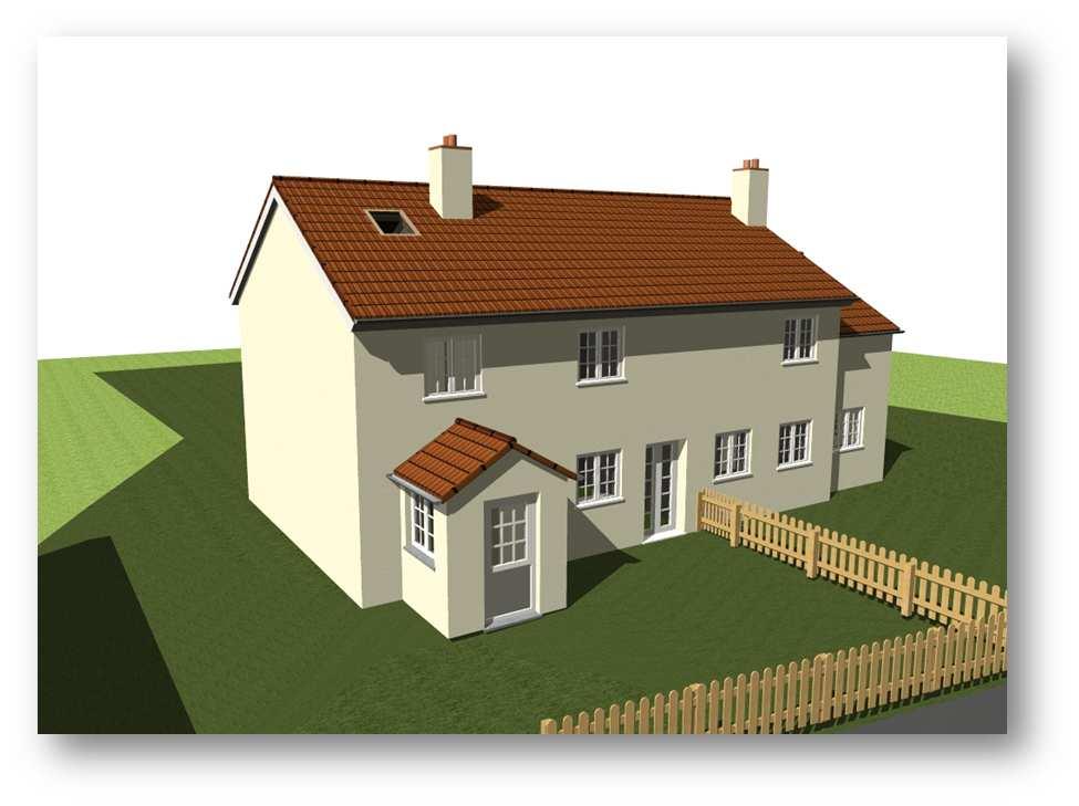
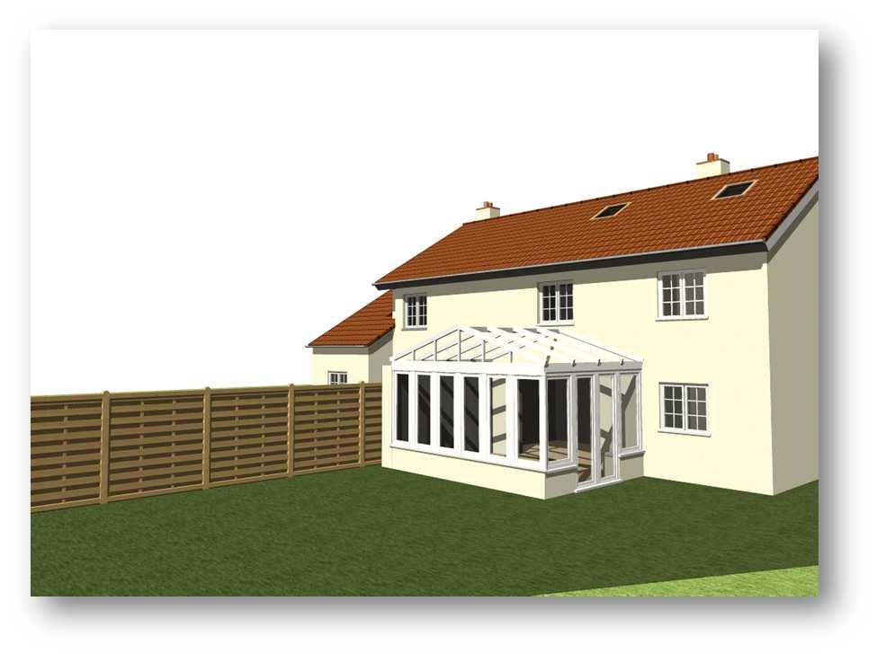
10 10
11 1.5 Saved Projects As you proceed through this course you will see reference to saved projects. E.g Project saved as tutorial1-2.cyp You can download the project at this point and compare to your own should you have any difficulty. 1.6 Documentation I don t intend to repeat the contents found in the Visual Building documentation, but I will refer to it many times. So before you start ensure that you have downloaded the latest documentation from: You can download this as a pdf and refer to it as you proceed through this tutorial. Because the documentation is constantly being updated any page numbers may change, so I will refer to various contents using paragraph numbers. 1.7 Videos There are 50+ tutorial videos available on the website. These are hosted on and can also be located by searching Youtube for visualbuilding. The videos concentrate on specific individual tasks, whereas this course covers the wider aspect of a complete project. 1.8 Questions and Feedback Your questions and feedback are very important to us. If you have any questions, or any suggestions, then please them to customercare@visualbuilding.co.uk. We also will publish interesting questions and suggestions that we receive via onto the forum, (anonymously) Alternatively you can add your questions and comments via the Visual Building forum at We prefer the forum route because then all our users benefit from the question and answer. 1.9 Preparation If you have not already installed Visual Building you should do so now. You can use any version of Visual Building. You can also use the trial version of Visual Building downloadable from After installing, locate the program in the start menu and right click on the entry and select Properties. In the Visual Building Basic 4 Properties panel select the Compatibility tab and select Run this program as an administrator. This will allow us to access and update program settings and templates in the reserved Program folder. 11

12 Failure to do this may result in not being able to save templates. 12

13 2 Start Visual Building This is what Visual Building looks like at startup. There are no toolbars showing at the moment. If your screen looks like this, then you are using the previous Toolbar based UI and should update your Visual Building in order to make use of this training course. 13

14 2.1 Start New Project Select the File tab General group New tool. Note in future this will be referenced as File-General- New. A new 2D new window will appear, titled New Project1: 2D View In the Projects tab a new Project tree is also created Every new project will look like this, and will consist of a Building 1. The Building contains a Ground floor and the Ground floor has a Floor Plan. As we add additional buildings, floors and plans to our project this tree will increase. Projects consists of Building and Views Buildings consist of Floors Floors consist of Plans and Layers The Environment currently contains the square plinth, compass and origin marker. These are all visible in the 2D View. The Views section in the project tree contains the current view called New Project1: 2D View. This is currently red, indicating that it is our current view, because it is our only view. Whenever an entry in the project tree is in red, then it means that it is part of the current view. You can hide components in the project tree, by clicking on the tick box. Deselected items will then not appear in the current view. For example deselecting the Environment entry will cause the environment to disappear from the 2D view. Right click on the Environment entry in the tree and from the context menu select, Select as current element. This results in the environment and its contents becoming active. 14


15 Using this context menu you can also rename an entry, and examine its properties. Learn how to use and control the Project tree and you will be able to control your project. 2.2 Create a 3D View At this moment we only have a 2D view of our project and so we will now create a new 3D View, by selecting View-New Views-New 3D View. A 3D view is created showing the same almost empty project as our 2D view. You will also notice a new entrée in the project tree named New Project1: 3D View and it automatically becomes our current selected view. 15

16 You can move and arrange the 2D and 3D view windows as you wish. There are also tools on the ribbon bar tool bar that will automatically arrange the windows. The most useful being the Arrange vertical tool located at View-Windows-Arrange vertical. This results in all active 2D and 3d Windows to be arranged as selected: Not that only one window can ever be active at any one time. The current active window is selected by clicking on it, however any changes made in any window are immediately updated in all other windows. 2.3 View Window Context Menu Each view window has its own properties and visibility control. Select the 2D view window, and then right click on it to activate the context menu: 16


17 Select the Visibility menu entry to display the Visibility dialog: This is where you can select what is visible in each view. This is not a global setting and applies only to the current view. Click OK to close. Select the 2D view window again, and then right click on it to activate the context menu again, and this time select Properties, which will activate the 2V View properties dialog: This dialog allows you to set the scale for this view. Each 2D view window can be set to its own scale. Click OK to close. 17

18 Now select the 3D view window, right click on the 3D view window to activate the context menu. Selecting Visibility will display the 3D View visibility dialog, the same as described for the 2D window. As before, each 3D view window has its own visibility properties. Select OK to close. Right click again on the 3D view window and from the context menu this time select Properties to activate the 3D view properties dialog: The 3D view properties dialog contains 8 tabs on the left side of the dialog. Simply click on each tab to view the properties in each tab. We will refer to these tabs later. Remember that each 2D and 3D view window has its own visibility set of properties and each 2D view window has its own set scale. 18
19 3 2D Plan View Drawing Building 1 The first 2D Plan view will represent part of the building built in As described earlier, it will eventually consist of 4 buildings representing different parts of the actual building. 3.1 Determine the Scale The scale of your project depends upon several factors: The scale requirement. Specific requirements may require a specific scale. The paper size. The paper size may be determined by the requirement and available printers. However using a pdf printer driver (see Visual Building forum for a free download), you can print to any pdf paper size without having that printer or paper size. You should also take into account what else you want to display on the paper. Don t forget to allow for information boxes and other text detail. Project size Is this a simple residential 5m x 5m plan, or a complex commercial site plan measuring 100m x 100m Plan Layout. Do you want to show a single plan per sheet or multiple plan views, elevations on a single sheet? Please note that Visual Building Professional and upwards support the Presentation Layout feature that allows you to present multiple 2D views on a single sheet. Visual Building Basic and below provides only for a single view per sheet. For example if I want to print out in A3 size for a project is 15m x 12m, what scale do I need? A4 Sheet Note the size of an A4 sheet is 210mm x 297 mm (8.267 x ). At 1:100 scale I could fit a 21 m x 29m project onto an A4 sheet. At 1:50 scale I could fit a 10.5 m x 15m project onto an A4 sheet. A3 Sheet Note the size of an A3 sheet is 297mm x 420 mm (11.69 x 16.5 ). At 1:100 scale I could fit a 29.7m x 42m project onto an A3 sheet. At 1:50 scale I could fit a m x 21m project onto an A3 sheet. Our first drawing will be the 2D Plan view in A3 and the building that we wish to draw is approximately 17m x 12m, so we could feel comfortable with a scale 1:50. It is possible to change the scale, but sometimes such a change may upset carefully positioned text labels, so it s best to get it right, but all is not lost if you make a mistake. The width is the total width of the project, including extensions. 3.2 Set the scale Select the 2D view, right click on it and select Properties. Set the scale to 1:50 19


20 3.3 Change Environment Size The environment is the green 3D slab in the 3D view and the 2D square in the 2D view. Select the Environment entry in the Project tree, with a Ctrl + left click to make it the current selected item in the tree. In the 2D view double click the 2D environment square to activate the Area properties dialog: The default size of the environment slab is 50m x 50m. This can be changed at any time or doesn t even have to be changed, but we will change it to 20m x 20m. 20
.")
21 With each window selected in turn, click on the View-Zoom-Show all to zoom into the full view for each window. Project saved as tutorial1-2.cyp 3.4 Change Compass Orientation In the 2D view window you can see the compass (bottom left of 2D view window). To change its orientation, select it and then double click it to activate the North arrow dialog: Change the value in the Angle field to change its direction. You can also change the position of the North Arrow compass within this dialog, or simply drag it to a new position. We will make no change and select OK 3.5 Create a Guideline Layer You can add guidelines to your project and using the View-Visibility-Guidelines On / Off tool, you can hide and show them as you wish. To introduce and demonstrate layers, we will create a new layer to keep our initial construction guidelines on. 21
. This new layer can now be selected like other elements within the tree.")
22 This is not essential and can be skipped. We are going to create a new layer on our Ground floor. In the Project tree right click on Ground floor, and from the context menu select New Layer. The Layer dialog will activate: Name the new layer as Guide lines (or any meaningful name). This new layer can now be selected like other elements within the tree. Now that this layer is our current active layer, anything that we add to our project they will be associated with this layer. Elements are always added to the current selected layer or floor. For example in our next step to add guide lines, if we did not create the layer, the guide lines would appear on the Floor Plan layer. 3.6 The Grid You can switch the grid on /off using the View Visibility-Grid on/off tool icon. If you right click on the grid tool, you will activate the General settings dialog. If you then select the Grid dialog tab, you can change the grid properties: We will set our grid size to 100 cm to help us position our guide lines in the next step. 22


23 While this General setting dialog is active, take a quick note of the other dialog tabs: Units: This is where you can change your measurement system. Selection: Defines how and what elements are selectable Snap: Defines how and what elements can be snapped to Tools: You can disable specific tools 3.7 Add Guide Lines It s possible just to draw your walls directly onto your floor plan, using just the grid to position the walls. There are also additional Constructional support tools to support the placement of walls and other elements. In this example we will use guidelines to precisely place our walls. We will first place the guidelines and then snap the walls to the guidelines. Select the 2D & Layout-General-2D Guidelines tool and additional guide line tools will appear. Place a vertical guideline on the origin marker. These guidelines will represent the internal wall positions of our external walls, and our next guideline position. Select the Vertical guideline, and click 3.73m left of the origin marker. To place the guideline exactly 3.73m, using our first guideline as a reference, click on the Numeric guideline tool (bottom right in the above image). Then click on the reference guideline and click again anywhere to the right of the reference guideline, and the following dialog will activate: Enter the desired distance of 3.73m; press OK and the new guideline will appear. Repeat for the horizontal guidelines, the first 2.91m below the origin and the second 2.91m above the first horizontal line using it as a reference point. 23

24 If this didn t work, please ensure that you have Snap enabled. To check, right click on the View Visibility-Grid on/off tool, and select the Snap dialog tab. Check that Enable snapping is ticked. If successful, your project should look like this: Project saved as tutorial1-3.cyp 24


25 3.7.1 Changing Guideline Style and Colour You can change the guideline style and colour by right clicking on the Guideline tool (e.g Vertical guideline) to activate the Guideline properties dialog: Click on the Appearance button to activate the Line properties dialog: You can now change the style and colour of your guidelines. 3.8 Placing Walls Walls are selected from Walls tool located at Building-Constructional Wizard-Walls. Selecting this tool will display an additional 6 wall options. These are 6 different wall styles with different wall sizes and properties. These wall tools also have a sub menu showing the different placement methods. 25

26 If you right click on the Building-Construction elements-walls tool, the Wall properties dialog is activated: This dialog has a lot of detail and a lot more detail hidden away, making this a very powerful tool. You can simply change the wall thickness and start entering your walls using that defined thickness. Change the thickness to 0.3m and then exit the dialog with OK We will now place our 0.3m thick wall using our guidelines. Left click on the Building-Construction elements-walls tool to select the Wall tool, and then the placement method. Note the status bar in the bottom left of the screen now gives you information concerning the tool you are using. Note that your mouse cursor has also changed indicating that the wall tool is active. Click once on the top left guideline intersection, and move the mouse to the top right guideline intersection. A wall will follow the cursor, both in the 2D and 3D view. Before you place the wall with a second mouse click, use the keyboard key combination Ctrl + W to define how the wall should snap to the guideline. There are 3 snap positions, that each Ctrl + W will rotate through: Centre line, Inside wall edge and Outside wall edge. Our guidelines are based on internal wall measurements so we will snap our wall to the inside edge. Click on each guideline intersection until you have completed your 4 walls. After completing the 4th wall you can cancel the wall tool with the Esc key, or alternatively right click and from the context menu select Cancel with Esc. 26
27 Your project should now look as follows: 3.9 Changing the Wall Style The default wall style is the hatch pattern. If you prefer an alternative hatch or a solid colour proceed as follows: Right click on the Building-Construction elements-walls tool to activate the Wall properties dialog as before. Alternatively double click on any wall placed in your project. 27


28 Now select the Layer construction tab which then displays as follows: You will see the current hatched being selected. To change this to a solid colour, click on the Material button as indicated above. This will display the Building materials dialog: 28


29 Ignore these advanced features and click on the 2D Display tab, which then displays as follows: Different hatch styles can be selected from the drop down list: Select Monochrome and then from the Fill colour drop down list choose a solid fill colour: 29

30 Select OK will accept your selection. Select OK again to exit the wall properties dialog. Ok - That changes the wall style of a new wall, but how to change the style of a wall already placed? In either the 2D or 3D view, select the wall to be edited and then double click on it. This will activate the wall properties dialog as above. A few examples of different wall styles that can be easily created: Our project however is required to show cavity walls 3.10 Creating Cavity Walls If you don t need to show cavity walls within your project, you can skip this section. To create a new or load an existing cavity wall design, return to the Layer construction dialog. That s achieved by right clicking on the Building-Construction elements-walls tool to activate the Wall properties dialog as before, and then selecting the Layer construction tab: 30

, a cavity wall 10 mm render, 100 mm brick, 50 mm air gap, 100 mm brick and 10 mm plaster.")
31 Wall designs can be saved as templates. To load a previously created cavity wall click on the Open template icon (indicated above). The above loaded template shows a 100mm facing brick, 50 mm cavity, 40 mm insulation, 100 mm lightweight block and then 13 mm plaster. The total of these wall components provides a wall thickness of 300mm.My project requires a 390 mm solid wall (built 1750), a cavity wall 10 mm render, 100 mm brick, 50 mm air gap, 100 mm brick and 10 mm plaster. The wall that we require in the first building is a solid wall 370 mm thick with 20 mm of rendering on the outside. There is no rendering or plaster on the inside. Clear all existing layers, by clicking on each layer in the display in the dialog and press Delete selected layer, until all but one layer are deleted. Alternatively you can click on the New Template icon in the bottom right of the dialog. 31


32 You now name the only visible layer as Solid fill and set its thickness to 0.37m. Now to create the external render, click on the Insert new layer outside button, and name the new layer Render and set its thickness to 0.02m. You can also change the 2D hatch / fill patterns for each layer by clicking on the Material button, and then select the 2D Display tab. Or You can select from the list of materials, where each material type has its own fill style defined. Now save your template using the Save template button in the bottom right of the dialog. You can view and load previous templates using the adjacent Open template. If you find that you cannot save any files, please refer to section 1.9 at the start of this document. If you want to save the current wall template as the default wall style for this wall type, then click on the Save as default button located 4 th down top right of the dialog. We will now delete our 4 walls in our 2D Plan, by selecting each wall and pressing the Delete key. We will do this so that we can draw our walls using our new wall template that we just created. Now redraw the four walls as before. If you zoom into the wall, you will see we now have our solid fill wall with render. Remember to be sure that the walls are drawn on the Ground Floor Floor plan layer, by ensuring that this is the current selected layer in the Project tree. 32


33 If you accidently draw a wall or any element on a wrong layer, e.g the Guide line layer, you can move the element by right clicking on it, and from the context menu, select Move to layer: None of this changes how the wall appears in the 3D view, that s for another time Renaming the Building We will now rename this Building 1 to Building To so just double click on the Building 1 entry in the project tree, and in the activated dialog enter the new name Building 1750 You can change the name of any project tree entry in a similar way. Project saved as tutorial1-4.cyp 3.12 Adding internal Walls We will now add some internal walls to our Building 1750 We will select another wall type for our internal wall, using the Non supporting wall (interior): Click on this wall type, and then the placement method. Right click on this and you will display the familiar Wall Properties dialog, where you can set the new wall thickness to 0.10 m: 33


34 Click on the Save as default button in this dialog so that this becomes the default wall size for this wall type. We will place our first internal wall along the centre guideline. This is in fact a party wall between the two properties forming the semi-detached cottage. To place the wall select the Non supporting wall tool, and then click in the 2D View at the point where the guideline crosses the north horizontal wall. The second click should be where the guideline crosses the south horizontal wall. The wall should be snapped to the centre line of the wall, so there is no need to use Ctrl + W After the second click press Esc to end the wall tool function. As soon as the wall is placed you will note that 2 rooms have been created named Room 1 and Room 2. This confirms that you have a good wall connection, as the room will only be created if wall connections are good. We have used internal wall measurements to create our plan, and so we will now place our internal horizontal wall 3.2m from our south wall s internal edge. Use the Numerical parallel guideline tool again, using either the wall edge or the lower horizontal guideline as your reference point. 34


35 When you have created your new guideline, you can draw your internal wall along it however this time snap to the lower edge of the wall. Again, notice how the room names are created Setting the Wall height We have not yet defined the floor ceiling height for the rooms in this building. This is achieved by either by double clicking on the Ground floor entry in the Project tree, or by right clicking on the Ground floor entry and selecting Properties from the context menu. This will activate the Ground floor properties dialog: Our measured floor to ceiling Clear height is 2.02m. Our Rough height is 2.14 m. The diagram in the dialog helps explain these measurements. Entering these values you will notice the walls will become shorter in the 3D view, but there is no change in the 2D plan view. Project saved as tutorial1-5.cyp 35

36 3.14 Adding Windows At this point we will add some windows. There is quite an extensive set of windows, which you can edit and resize. If you have Visual Building Premium version you will also have access to the Window Construction tool allowing you to create completely new window designs. We will use the Window construction tool later, but for now we will edit and resize windows from our standard window catalogue. There are in fact two window catalogues. The catalogue called Window is based on objects. These can be resized to a certain extent. The newer form of window is contained within the Window construction catalogue. These objects are created using the previously mentioned Window construction tool. These window types are more versatile and more editable and where ever you have a choice, you should use this window type. There are two ways to access both of these window types, either via the catalogue or via the tools in the Ribbon bar. 36


37 Selecting windows via the catalogue From the catalogue tab select Construction elements. You will find both windows types each have their own catalogue entry Select any window in either of these catalogues and drag into its position in either the 2D or 3D view. You should drag it onto a wall. When the window is in a valid position you will see an arrow appear. This indicates the opening direction of the window. You can adjust this direction, by moving the mouse cursor closer to either edge of the wall. When correctly position do a left click, and the window will be placed. Once placed, you can edit the window s dimensions, by double clicking the window to activate the Windows s dialog, which differs depending upon the window type that you selected. 37


38 For now, we will concern ourselves only with setting the width and height of the window. We will set our window width to 0.98m x 0.94m Selecting windows via the toolbar Alternatively and preferably, you can select windows using the window tools in the ribbon bar. Right click on the Building-Constructional elements- Window tool in the toolbar and the Window properties dialog will appear. As before you can resize the window, but now you can placed the window multiple times, just by clicking on the wall Window Placement tools There are Constructional support tools available to allow you to place a window exactly. After selecting the window, move the window into its approximate position in the wall, but instead of a left click, make a right click to activate the context menu. You can now select several tools allow you to place the window midway between two points, or a specific distance from a point. Note the latter is measured from the midpoint of the window. 38

39 After placing the windows, you can now select each window and move it to a new position. If you find the window is snapping to something, then switch of the grid. There are many other options concerning windows, and we will return to these later. If you place a window facing the wrong way, you can easily correct this by selecting the window, and then activating the context menu with a right click and selecting Change opening direction. You will also notice a number (0.90m) by each window. This is the sill height for that window, as specified in the Window properties dialog. You can hide this measurement by the following: Right click on 2D View window, and from the context menu select Visibility, and the Visibility dialog will display. Scroll down the tree to Labels and deselect Sill height, and you will see it no more. Project saved as tutorial1-6.cyp 39

40 3.15 Adding Doors Placing doors is very similar to placing windows. The Door tool is also located in the same tab and group as the window tool. You select a door from the catalogue and click on the wall. Right click on the Building-Constructional elements-door tool to activate the Door Properties dialog. Select a door from the drop down list provided by the Selection button. If you click on the 3D button an additional window opens allowing you to inspect the door as a 3D object. You can also set the width and height of the door before placing it. 40


41 After placing the door, the opening direction, and hinge side are indicated with an arc of the door swing. If you wish to change either the opening direction or hinge side, the right click on the door and from the activated context menu select Change opening hinge or Change opening direction 3.16 Adding a wall cut-out Where you have a situation where you need to cut out a section of a wall, or add a doorway that has no door, you can use the Building-Constructional elements-wall cut-out tool. Clicking on wall cutout tool and then the Free positioning tool, will allow you to place the cut out in the same manner as a door or window. If you right click on the cutout tool you will activate the Cut-out properties dialog, where you can set the width and height. You should also note that if a wall cut-out is to be used as a door, then you should set the sill height to 0m. 41

42 You can also double click on a placed wall-cut to activate the wall-cut-out properties dialog. Project saved as tutorial1-7.cyp 3.17 Creating another floor Everything that we have created so far has been on the Ground floor. We will now create a second floor, using the ground floor as our template. We will copy the wall layout and dimensions and the windows, but not the doors. On the Project tree ensure that the current selected layer is Ground floor Floor plan with a Ctrl + left click on it. Now right click on Building 1750 to activate the context menu, and select New Floor above 42
 that the floor height is the same as the ground floor and so will not change any of the height values.")
43 The New Floor properties dialog is activated. This is similar to the dialog that we activated when we wanted to change the floor height in section It has an additional tab named Transfer. We will assume (for now) that the floor height is the same as the ground floor and so will not change any of the height values. Click on the Transfer button that shows the dialog tab that allows us to choose what ground floor elements we want to copy to the new floor. Locate within the tree Cut-outs and Doors and deselect them, as we do not wish to transfer them to the new floor. Leave Windows selected. Click on the Layers tab and deselect Guide Lines as we do not need another set of guide lines. Click on OK and a new floor is created named Upper floor. A new floor entry appears in the project tree and the 3D view is updated to show the new upper floor. The 2D Plan view is also updated, but this is not so obvious at the moment. Note that only the windows have been copied from the ground floor to the upper floor. Project saved as tutorial1-7.cyp 43
44 3.18 Creating the Attic First you must consider if you want to create another floor. If your attic has a floor or any walls, then yes, you should create a new floor for the attic, and eventually place the roof on the attic. This scenario will be the case for most situations. However if your attic has no walls, including gable walls, then you can place your roof directly on the upper floor and adjust its height accordingly. In our case our attic does have its own floor and the roof also has gable ends. So we will create a new floor to be our attic. Creating the attic is almost identical to the last section, except this time we will not transfer any doors or windows. So repeat section 3.17, but this time do not transfer any windows. You can also name the new floor Attic. 44

45 3.19 Adding a roof With the 2D view selected, ensure that the Attic is the current selected floor. Click on the Building-Roof anddormers-roof Construction-Insert Roof tool and 3 additional roof tools will appear, allowing different methods of inserting a roof. Select the Insert Roof on Contour tool. Then in the 2D plan view, click anywhere on the wall contour. The Roof construction dialog will activate. 45


46 Click on the 3D button and a 3D view of the roof construction will appear in its own window. All elements of the roof can be selected via the dialog tree, for example selecting Roof side 4 in the tree; will select that specific roof side in the 3D view. Similarly clicking on a roof side in the 3D view will select an entry in the tree. You can rotate the 3D model roof, by selecting it and dragging the model with the mouse, thus allowing you to examine all elements. We will now assign a Gable end to Roof side 4. Select Roof side 4, and from the Roof profile drop down list select Gable. Select Roof side 2, and apply a Gable to that also. 46

47 The result shows a roof with a gable end at each end. Select Roof Side 3 and in the Roof construction dialog set the Pitch to 30 degrees, and press the Tab key to accept the change. Select Roof Side 1 and in the Roof construction dialog set the Pitch to 30 degrees, and press the Tab key to accept the change. Each time you edit an element in the dialog, the 3D roof model is updated Select OK on the dialog and the roof is applied both to the main 3D view and the 2D plan view. Project saved as tutorial1-8.cyp 47


48 3.20 Remove Gap in the Attic Gable Wall You will notice a gap in the roof at its apex. This is because when we created the Attic, we used the Upper floor s properties, including the height of the floor. At 2.16m this was insufficient to reach the ridge height of the roof. To rectify, in the Project tree, select the Attic, and right click on it to activate the context menu, and then select Properties, to activate the Attic floor properties dialog. Set the Rough height to anything higher than the ridge height. This value can be anything as the roof will cut the wall height automatically. Edit 2.16m to be 3m, click and the gap will disappear Remove unwanted Purlins in Gable Wall Not all buildings have their purlins extending through the gable wall as seen here. You can hide these purlins and all other wood construction by right clicking in the3d view, and then from the context menu select Visibility. In the Visible categories tab, scroll down to Roof constructions / Roof and deselect Wood construction. Press OK and all timbers will disappear from your view. A better solution however is to shorten the purlins. (Reverse the previous paragraph to show the purlins again). Ensure that Building 1750 Attic is your current floor in the 3D view. Then double click the roof to activate the Roof dialog. In the dialog click the 3D button to see a 3D view of the roof within the 48


49 dialog. You can resize the 3D roof view to get a better view of it. In the dialogs 3D view you can also drag the roof and rotate it to view the roof from different aspects. Clicking on the 3D model will highlight the roof side in green, and also highlight the entry in the roof dialog s tree. In the dialogs tree, select Gable end details, and set the Visible if overhang > 1m. (Its default was set to 0m.) By setting the value to 1m the purlin will only be visible if the overhang is ever > 1m, which it isn t and so does not show Adding Eaves detail In the Roof Properties dialog tree select the Eaves details entry, and you will see a cross section view of the eaves. 49


50 You can now select your chosen Cornice; we will use Cornice type 2. We will also set the angle of the Facia board to 90 degrees. Click OK to update the 3D view: 3.23 The Roof Overhang The default roof overhang of 0.5m is a bit extravagant in our case, and we need to set it to 15cm. Double click on the roof again to activate the Roof dialog again. In the Roof dialog tree select each Roof side and change the overhang from 0.50 m to 0.15m 50

51 3.24 Trim Rafters We can now also trim the rafter by selecting a horizontal Eaves cut for the rafter, thus preventing the rafter extending through the soffit Adjusting Roof Height Upper floor height is correct, but our roof is still sitting too high upon Attic floor. So that we can understand what is happening, we shall create a cross section view of our roof. Ensure that the current floor in the Project tree is is Building 1750 Ground floor. Close the 3D view, so that only the 2D View window is open. In the tool bar select the New Section View tool and then drag a rectangle through the plan as shown below. It s important that the rectangle cuts the building as shown, because this is where the section will be placed 51
52 As soon as you complete the section rectangle a new section view is created: In the Project tree select the Attic Floor plan to be your current floor and you now be able to select the roof in the Section A-A view by double clicking it. We will now move our roof down by -0.74m. 52

53 You can change the height that the roof sits upon a floor also within the Roof Construction properties dialog. For example to move the entire roof down 0.74m, enter 0.74 m and then press Apply, and then OK. The result is: Project saved as tutorial1-9.cyp 53


54 3.26 Changing Tile Textures You can drag and drop any material or texture directly from the catalogue onto the roof and timber elements. Alternatively, you can specifically select an element and then select the material or texture. Double click on the roof to activate the Roof properties dialog. In the Roof construction properties dialog tree, select General Materials. Each element has 3 selections. The first (default roof tile Frankfurter, allows you to specify the texture used in either the 2D or 3D view. The next option is to select a material from the predefined materials list. The 3 rd option allows you to set the texture repeat size and rotation. For our roof tile we will continue to use the default roof tile; however we will change the texture size to reduce the actual tile size. To achieve this click on the drop down to display the Texture dimension options: The default texture size is 1.0 m, which you can change to 0.5m to achieve a better tile size. This value will depend on the original texture size. We may go into this in more detail later when looking how to create our own roof tiles. In a similar way, now change the colour of the ridge, but this time use a solid texture instead of a tile texture. Using the Transfer Texture and Transfer Material tools, you can copy texture between elements. To copy the texture from ridge to the Gable end boards click on the Transfer Texture tool, then click on the source element and then the target element. The texture will be transferred. 54


55 Let s now drop a material from the Catalogue onto the wooden cornice element. Find the White material and drag onto the Cornice element, and the material will be applied. Project saved as tutorial1-9.cyp We have no need of the section elevation view, so we can now delete it. On the 2D view select the Section A-A line (it will turn red when selected), and press the Delete key, and after a confirmation, the 2D section view will close and also be removed from the Project tree Renaming our Rooms We will now rename the existing rooms so far created. This will also help us in the course when we need to reference a room. 55 The current rooms names Room 1, Room 2 were automatically given when we created the rooms. Make your Ground floor Floor plan your current floor with a Ctrl + left click in the project tree entry. In the 2D View, select Room1, and it should highlight with a red cross-hatch, indicating that the room is selected. If you now double click the selected room, you will activate the Room properties dialog. This dialog will allow you to change the room name and modify other room properties.


56 The General entry in the dialogs tree will allow you to change the room name currently being displayed, so we will rename this to Kitchen. You can also add your own comments concerning this room. Click the Labelling tree entry in the dialog and you will see that you can add additional information alongside the name that is automatically calculated and displayed. For example we can automatically display the Floor area for the room, by selecting Floor are, and if required a prefix from the drop down list. The Room labelling General entry in the tree allows you to switch off the automatic positioning and text display. The automatic positioning can also be switched off, just by dragging the text in the 2D view. 56


57 We can also elect not to display the room names in the adjacent property. If you xan see two sets of text in the room, that because you have both the Upper floor and Attic being displayed. If you deselect the Upper floor and Attic in the Project tree you will see only the currently selected Ground floor. Now repeat for each floor, i.e. the Upper floor and attic. In the Attic we have the same room plan, but here we will delete the horizontal wall, simply by selecting it ()it will turn red when selected), and press the delete key. When the wall is deleted the attic becomes a single room again, which we will rename as Attic Project Tree Visible floors When selecting and deselecting the floors in the Project tree, you should note that the selection is specific to the current 3D or 2D view. You could for example view only the Attic floor in the 2D view and view both the Ground floor and Upper floor in the 3D view. In the Project tree, ensure that only the Ground floor Floor plan is selected. 57

58 Now click on the View-New Views-New 2D tool. A new 2D view is created with all possible floors being displayed. Deselect all floors in Building 1750 except the Upper floor. Now click on the View-New Views-New 2D tool again, and this time deselect all floors in Building 1750 except the Attic. You should now have 3 x 2D Views and 1 x 3D view. Click on the View-Windows-Arrange Vertical tool and your view windows will automatically rearrange. With 2D View window in turn deselect the Environment layer and then click on the Show All tool. So not to get confused we shall now close the last 2 2D views we created. You can close such a view either by click in the window close icon in top right of each window, or right click in the Project tree entry for each view and select Close view from the context menu. Project saved as tutorial1-10.cyp 58
 The new building can have different Floor properties to the existing building.")
 It s easier to switch off individual buildings, allowing you present visualisations with and without an extension. c) Your new building may have a different ground level to your existing building.")
59 4 Adding an extension Building 2 We will now add an extension to our existing plan. In this example we will create a new building, called Building 1980 Extension East. It is not essential to create a new building to add such an extension, but there are several advantages in doing so: a) The new building can have different Floor properties to the existing building. This is the case here where our new extension has a different floor to ceiling height. b) It s easier to switch off individual buildings, allowing you present visualisations with and without an extension. c) Your new building may have a different ground level to your existing building. That s not the case here in this example. So don t think that the Building feature is restricted to creating new buildings, as it s a powerful feature allowing you to design more complex projects. To create a new building right click on the Project entry in the Project tree, and from the context menu select New Building. In the Building properties dialog that is displayed enter its name- in our case Building 1980 Extension East. Note that a Ground floor Floor plan is automatically created but there are no contents. In the Project tree select Building 1980 Extension East to be the current selected floor. You can now deselect all views except one of the 2D Vies and the 3D view. Click on Arrange Vertical in the tool bar. Your project tree should now look like this. You can see the floor plan of Building 1750 Ground floor, but you cannot edit it because it is not the current floor. You however can still snap guidelines and walls to the greyed out plan. We will not draw this extension in detail as it is part of the neighbouring building. We will now add the guidelines to Building 1980 Extension East - Ground Floor Floor plan to position the extension. 59
60 4.1 Edit Ground floor Then add the walls, the thickness and wall layer is not important. We also added a virtual wall using the Room Boundary wall type. (See for a detailed explanation) We then set the floor height. We then add the windows and doors. Dimensions and detail are not important for this adjoining building, so you could skip this section and just load the saved project to view. Project saved as tutorial1-11.cyp 4.2 Add Upper floor Right click on the Project tree entry Building 1980 Extension East and from the context menu select New Floor above. In the New floor above dialog select the options to Transfer all, and then click OK. This is a lesson in deleting unwanted objects transferred; in this case the doors and windows. In either the 2D view or 3D view select each door and window on this floor and press the Delete Key. 4.3 Add roof to upper floor You are just repeating the steps in section 3.18, but this time the roof is being added to the Upper floor and not the attic. 60
61 Adding a roof to the contour of our extension results in the following roof shape: We need to set every roof side to be a Gable, except for Roof Sides 1 and 3, which will remain as Hipped Roof. This provides the cut in the roof that we require fitting around Building We then need to change the overhang setting for each roof side from 0.6m to o.1m, except for the roof sides that are against the existing building, which should have an overhang setting of 0m 61
62 Then set the pitch of the Roof sides 1 and 3 to 30 degrees. While setting the pitch also set the roof height to 0.5m for Roof side 3, and 1.4m for Roof side 1. The different roof heights give us the required offset roof: Now remove the unwanted purlins, and increase the height of the Upper floor from 2.1m to 3m to remove the hole in the roof apex. Finally change the Eaves details to match those we set for the Building 1750 roof. Project saved as tutorial1-12.cyp 62
63 63
64 5 Adding an extension Building 3 Our third building will be in more detail because this is part of the property that we are interested in. 5.1 The Foundation We have already had a few questions, asking why we did not create a foundation for our buildings so far. Certainly if this was a new build, or the plans would require showing a foundation, then this possibly would have been our starting point. The first building section created in the project was built in 1750 and does not have any foundation at least not by modern standars. The solid walls have stood for 250 years and have not moved, so hopefully will remain solid for another 250 years. The second building section was part of the adjoining building and the foundation and details are of no interest. We will however add a foundation at the end of this chapter. The extension that we are about to create was built in the 1980 s and certainly does have a foundation. 5.2 Create Building 1980 Extension West To create a new building right click on the New Project1 entry in the Project tree, and from the context menu select New Building. In the Building properties dialog that is displayed enter its name- in our case Building 1980 Extension West. Note that a Ground floor Floor plan is automatically created but there are no contents. In the Project tree select Building 1980 Extension West to be the current selected floor. You can now deselect all views except one of the 2D View and the 3D view. (In case you still have others visible) Click on Arrange Vertical in the tool bar. You can see the other floor plans, but you cannot edit them because they are not the current floor. You however can still snap guidelines and walls to the greyed out plans. We will now add the guidelines to Building 1980 Extension West - Ground Floor Floor plan to position the extension. Once the guidelines are placed, we will place our wall. Again we will use a cavity wall. If you select the External wall tool, and the right click on it, selecting the Layer construction tab, you will see that you may not have the wall layer specification that you want. You can of course load any wall layer from the layout folder (it lives in Visual Building Basic\AEC\Layouts). If you wish to use a wall layer template previously used, as we have, then there is an alternative way of using the same wall layer template. Locate a wall where the wall layer template was used, double click on the wall, and from the activated Wall properties dialog, select the Layer construction tab. 64


 We complete such rooms with a special wall type, the Room Boundary wall type, found at the bottom of the wall type list.")
65 Now click on the Save as default icon (see above image). This will then ensure that this wall layout template becomes the new default for this wall type. Returning to Building 1980 Extension West - Ground Floor Floor plan, when we place our new external wall (remembering to use Ctrl + W to snap the walls outer edge to the guide line), we will use the desired wall template. After placing the 3 walls, you will note that no room is created. You should not place a 4 th wall over the top of the existing wall. Placing a new wall in parallel and adjacent to the existing wall is also wrong, unless of course this is how the building was constructed Room Boundary (virtual wall) We complete such rooms with a special wall type, the Room Boundary wall type, found at the bottom of the wall type list. Select this wall type and complete the 4 th wall side with it. You will know that the room is complete when the automatic room name appears. 65

66 We now need to set the room height. Double click on the Ground floor entry in the Project tree for this building to activate the Ground floor properties dialog. We will use the same values that we used in section 3.13, when we set the room height for Building Project saved as tutorial1-13.cyp 5.3 Adding Windows To add windows in this building we will follow the exact same process defined in section 3.14 Place any two windows at either end of the current building. 5.4 Create Upper floor We will now create a second floor, using the ground floor as our template. We will copy the wall layout and dimensions and the windows. We will be use the same procedure described in 3.17 On the Project tree ensure that the current selected layer is Ground floor Floor plan with a Ctrl + left click on it. Now right click on Building 1980 Extension West to activate the context menu, and select New Floor above The New Floor above dialog is activated. We will assume that the floor height is the same as the ground floor and so will not change any of the height values. Click on the Transfer button that shows the dialog tab that allows us to choose what ground floor elements we want to copy to the new floor. In this case we will select all, and then click on OK. 66


67 5.5 Create Attic Creating the attic is almost identical to the last section, except this time we will not transfer any windows. So repeat section 5.4, but this time do not transfer any windows. You can also name the new floor Attic. Alternatively you can transfer the windows and then simply delete them. 5.6 Extending the Roof You can either add a new roof with the exact same specifications as used for the roof in Building 1750 or better extend that roof to cover this building as well. We will extend the roof. In the Project tree, select Building 1750 Attic Floor plan to be the current floor plan. In the 2D View, select the roof and several roof points will become visible, together with the roof outline. Click a roof point to select it and click again in its new position to place it. Repeat for the other roof point. It s important that these points snap to the correct position otherwise you will get some unwanted effects in the roof. Project saved as tutorial1-14.cyp 67
68 5.7 Adding the Foundation Creating a foundation is just like adding a floor, except you add the new floor below the ground floor layer. How you proceed with creating the foundation depends on the type of foundation. Strip Foundation, Pad Foundations, Raft Foundations, Trench Fill Foundations and others are all possible to create and show. The foundation used and its specification will depend upon local ground conditions, building structural requirements and what your Building Control requires. In our example we will use a modern (450 cm wide x 100 cm deep) trench fill foundation, where the concrete is poured to within 20 cm of the top of the trench, and then for the foundation walls use 2 courses of block work to bring us up to the DPC. We first create the foundation walls. The foundation walls are 20 cm high are so lay 20 cm below the Ground floor. Ensure your Ground floor is the current selected floor, and then right click on Building 1980 Extension West and from the context menu select New floor below. In the New Floor below dialog, name the Floor as Foundation Wall, set the Rough Height to be 0.2m and switch off the Create automatic ceiling. Ensure the Transfer Tab is set to Transfer none. Click OK. Select the Foundation Wall as your current floor level and draw the foundation wall. To help identify this as being the foundation wall, you can drag a different texture onto the wall in the 3D view. We next create the foundation trench (filled with concrete). The foundation trench is 100 cm deep, but 20 cm is filled by the foundation wall, so we need another 80cm. Ensure your Foundation Floor is the current selected floor, and then right click on Building 1980 Extension West and from the context menu select New floor below. 68
69 In the New Floor below dialog, name the Floor as Foundation Trench, set the Rough Height to be 0.8m and switch off the Create automatic ceiling. Ensure the Transfer Tab is set to Transfer none. Click OK. Select the Foundation Wall as your current floor level and draw the foundation trench. You can use a wall to achieve this set with a width of 450cm. To help identify this as being the foundation trench, you can drag a different suitable texture onto the wall in the 3D view. Project saved as tutorial1-15.cyp You will need to provide a dimensioned section view of your foundation, which we will complete later using the section tool to create a new view of the foundation. The above screen shot show the 3D view with the Environment switch off. If you enable the environment you will see that it has become thicker to accommodate the foundation. Select the Environment in the Project tree and then double click the environment block in the 3D view. In the activated Area dialog uncheck the Enable automatic thickness and click OK. 69

70 6 Adding a Conservatory Building 4 The next extension to our project is a conservatory. In this case we will build the foundation first a work upwards. There are several methods you can use to design a conservatory. There is also catalogue of conservatories in the object catalogue: These can be created using standard window parts, and adding a standard roof, hiding the entire roof construction element and dragging a glass material onto the roof. These catalogue conservatories are OK if you only want a representation of a conservatory, but if you require something more bespoke and detailed then you can construct your own using basic components. If you are not interested in designing a conservatory, you can skip this section. I will save the completed conservatory as a completed model, which can be used in other objects. Note however that the conservatory that we are about to construct was built from basic components. 70


71 In most projects it may make sense to construct the conservatory timber and glass panelas as a separate project, save the result as a 3D model, and then import that 3D model into your conservatory. In this course however we will design and maintain everything within the single project. To create a new building right click on the New Project1 entry in the Project tree, and from the context menu select New Building. In the Building properties dialog that is displayed enter its name- in our case Building Conservatory. Note that a Ground floor Floor plan is automatically created but there are no contents. 6.1 Create Conservatory Base Wall Our conservatory has a base wall, which we shall layout using guidelines. Note that the base wall consists of 2 different wall heights. We have created a dwarf wall of height m and a high wall of 2.048m. Our wall consists of a different wall template 30cm thick with the following layout: 71


72 Previously we used the room height to set the height of our wall, but for this case we will use the height property that can be set in each wall s properties dialog. The other main procedure where we differ from previous methods is that we have created a separate layer for the High Wall. This was done because we want the high wall and the dwarf wall to be butted together, as opposed to how the two dwarf walls join. We also need to use the Room Boundary tool to complete the room because the Dwarf wall and high wall are not actually connected. The Room boundary is visible in the 3D view but can be hidden using the 3D View s Visibility setting, and deselecting Construction Elements Room boundary. Project saved as tutorial1-16.cyp 72
73 6.2 Add Conservatory Foundation Walls We first create the foundation walls. The foundation walls are 80 cm high are so lay 80 cm below the Ground floor. Ensure your Ground floor is the current selected floor, and then right click on Building Conservatory and from the context menu select New floor below. In the New Floor below dialog, name the Floor as Foundation Wall, set the Rough Height to be 0.2m and switch off the Create automatic ceiling. Ensure the Transfer Tab is set to Transfer none. Click OK. Select the Foundation Wall as your current floor level and draw the foundation wall. To help identify this as being the foundation wall, you can drag a different texture onto the wall in the 3D view. 6.3 Add Conservatory Foundation Trench We next create the foundation trench (filled with concrete). The foundation trench is 100 cm deep, but 80 cm is filled by the foundation wall, so we need another 20cm. Ensure your Foundation Floor is the current selected floor, and then right click on Building Conservatory and from the context menu select New floor below. In the New Floor below dialog, name the Floor as Foundation Trench, set the Rough Height to be 0.2m and switch off the Create automatic ceiling. Ensure the Transfer Tab is set to Transfer none. Click OK. 73


74 Select the Foundation Wall as your current floor level and draw the foundation trench. You can use a wall to achieve this set with a width of 450cm. To help identify this as being the foundation trench, you can drag a different suitable texture onto the wall in the 3D view. Project saved as tutorial1-17.cyp 6.4 Placing Windows and Door Panels Before we place any window panels, we should find a suitable panel and edit its size. Click on the Window Construction tool to activate the Window Construction dialog. In the dialogs catalogue locate and select the Window, simple design. The width of this window casement will be set to 064m and the height to The Sill height should be set to the height of our dwarf wall 0.46m. We should now edit the casements component dimensions such as its frame dimension. This is achieved by selecting the Profiles tab. Select the Casement and set the Profile width to 0.04m. Select the Frame and set its Profile width to 0.04m. On the Casement tab we can also define the opening mechanism to be Awning top hinged. 74


75 Click the Window sill tab and we can set the sill dimension and shape. You can also click on the 3D button to get a good 3D view of your window. Selecting the Outer Window Sill and Inner Window Sill in turn set their shape and dimensions. Select the Opening tab to set the Depth of the window. Setting this to 0.01m will ensure the window sits on its outside edge of the wall, opposed to the default of centre. Click on Save as default button in the dialog, so that we remember all our settings, and then OK. In the Project tree, ensure that the current Floor is the Building Conservatory Dwarf Base Wall, as this is where we will now place the window. 75


76 Before we duplicate this window, we can add textures /materials to the frame and sill. We will drag a Gloss White material from the catalogue onto the wood components of the window. You can now place another 5 windows to the left of the first window placement, in a similar way, but it s easier and more accurate to use the multiple copy tool Using Multiple Copy First, in the 2D view, select the window (it will turn red when selected), and then right click the selected window to activate the context menu. Select the Multiple Copy menu entry, and the Tool options dialog will activate. In Tool options dialog, set Clear distance, set Distance to 0m, set Number to 5 and direction to left. If your window does not fir to the wall end exactly then you have either got the window width wrong or your wall length wrong. 76

![] The Multiple copy tool is a very powerful tool and helpful in many similar object placements situations.](/docs-images/76/73746176/images/77-1.jpg "The next 2 windows panels that we will place are different width, so we will adjust the width in the windows properties before placement. Place the next two side panels.")
77 [I noted a bug here in that during the multiple copies, the sill dimensions were calculated on the underlying foundation size and were therefore too large, although we were placing the window on the dwarf wall. We resolved this by hiding the foundation in the 2D view by de-selecting them in the Project tree.] The Multiple copy tool is a very powerful tool and helpful in many similar object placements situations. The next 2 windows panels that we will place are different width, so we will adjust the width in the windows properties before placement. Place the next two side panels. You may notice problems such as sill overlap. This can easily be rectified by changing offending window s Inner window sill Overhang, left from 0.03m to 0m Our next two panels are in fact door panels. We can use the same panels, but change both the width and height properties before placing. Project saved as tutorial1-18.cyp 77


78 6.4.2 Adding Conservatory Timbers Now to place a 0.15m wall plate around the top of the windows. Use a Cuboid object found in the Objects/Misc/Basic Forms object catalogue. Drag it anywhere into the 2D window, and then double click on it to resize it. This will activate the 3D Object dialog, where you can set its width height and depth. Before you change any values, ensure that you have set Scale distorted; otherwise changing one dimension will rescale the other two. conservatory should be 0.05 m x 3.0m x 0.15 m. The timber to run along the top front of the To rotate a selected object use the rotation tools located in the toolbar. The Tool options dialog will appear allowing you to either click on the desired rotation or to enter it numerically. 78


79 When you have the correct value press Esc Key to enter the value. You can move the selected object in either the 2D or 3D view window, but it is difficult to place objects exactly in 3D, so it is best to do so in 2D. There is an alternative method where you can create an elevation view of your project and then move the object in the elevation view. This limits the object to moving only in 2 dimensions. Alternatively use the Selection-Move-Move tool which allows you to lock either the x, y or z planes, thus giving you greater control over placing objects. Note that this ribbon tab only appears when an object is selected. 79

80 The same principle is used to create the roof beams, which also have to be rotated into position. You need only place one beam in this way, and then use the multiple copy tool to place the remaining beams Adding Conservatory Roof Windows The roof windows were created from the same window used in the walls. The required length of the window can be determined by measuring the dimension in the plan and side elevation views. Resize the window to the measured dimensions. 80


81 You can now create a 3D object from this window. Select the Application drop down menu, and then select the menu entry Export 3D Formats 3D Object. This will activate the Export project dialog, where you should select Selected objects only. Save the object either to your desktop or catalogue. 81

82 You can now locate this new window object in your 3D Object catalogue, place and rotate it exactly as with the previous timber objects. Project saved as tutorial1-19.cyp Of course you can always use a standard roof in the same way the conservatories in the catalogue were created. 82

83 7 Cosmetic Changes to Project The following was completed during the next step, but was just a matter of repeating what had already been achieved in previous sections. Add 3 windows rear of Building 1750 Add foundations to Building 1750 Add foundations to Building 1980 Extension East Delete Section A-A Rename the Conservatory from Room 1 to Conservatory. Project saved as tutorial1-20.cyp 7.1 Moving select Objects to New Layers When we created the conservatory timbers we created them as part of the Dwarf Base Wall. You can verify this by switching the Dwarf Base Wall on/off in the Project tree for either the 3D view or 2D view. Let s create a new layer called Conservatory timber and then move those timbers to this new layer. This will then allow us to switch on/off the timbers individually. We could also create an alternative style of conservatory timbers on yet another layer if we wished. So to be clear what we are editing, ensure the 2D view is your current window, in in the Project tree, disable all buildings except the Building Conservatory. (You also do the same in the 3D view if you wished, but I suggest not). Your Project tree and 2D view should look like this. Right click on the Dwarf Base wall entry to active the context menu and select New Layer. The Layer dialog will then activate allowing you to enter Conservatory Timbers as the new layer name. the 3D view becomes selected. If you now drag a selection box around the conservatory in the 2D view, you will see that the entire conservatory in We can switch off the items that we don t want to select, by right clicking the 2D view, select Visibility from the context menu, and disable all the construction elements. 83


84 If you now draw a selection box around the Conservatory in the 2D view, you will see only the timbers and windows now become selected in the 3D view. While these are selected, right click the 2D view and from the context menu, select Move to layer, and a list of all floors and layers will display. Select the Conservatory Timbers and all the selected objects will move to the new layer. You can verify these have moved by, by switching on/off the Conservatory Timbers, within the 3D view. This is a powerful feature and allows you to move almost any object between floors or layers. Also hopefully now you will begin to realise that Buildings, Floors and layers are all layers within your project. Remember to enable your Construction elements again in the 2D Views Visibility dialog. Project saved as tutorial1-21.cyp 84

85 8 Adding a Chimney We will add a chimney to Building 1750 Ground floor, so ensure that this is your current layer. There is a chimney tool in the tool bar which when selected will activate the Chimney properties dialog. Set the Chimney dimensions and its height above the roof ridge. Place the chimney in the 2C view and it will automatically extend through all floors. We have placed the chimney on the ground floor, and so it will appear when the ground floor is selected. Our chimney is not the same width through its height, so we will just add the core column dimensions for now. Project saved as tutorial1-22.cyp 9 Creating an Inglenook To accompany our chimney, we will now reproduce a small inglenook fireplace. To achieve this we will use the 3D Constructor tool. This tool is a feature only in the Professional and Premium versions. If you are not using these versions then you can either skip this section. You can also skip this section if you are not interested in an inglenook fireplace; however the methods and tools used here are tools that you can use in many similar situations and so well worth understanding. To accomplish this you can create within your current project or start a new project. I have opted to create this in a new project. 9.1 Method 1 Using Outline shape We will first create a scaled measured outline front elevation view of the inglenook. 85


86 We will set out some guidelines to define our block size 1.68m x 2.04m The side walls are 0.23m wide and the arch base ia 1.27m with a peak at 1.36m We will now use the 2D Graphics tools to draw the outline, first drawing the arch between 3 points. The dimension lines are solely for reference here and are not required. Using the 2D line tools complete the front elevation outline. We will use the Edit 2D Graphics tool to create a contour from our outline. This toll is located in the Edit tools. 86


87 Select all the points by dragging a selection box around them. Then click on Create Contour. We will then extrude the 2D outline into a 3D object, using the Extrude solid / extrude 2D contour Using the Rotation tool, rotate the 3D Construction object by 90 degrees in its x-axis. Note that the Ribbons selection tab only appears when you have an object selected. 87


88 We can now edit the 3D Construction objects dimension, in this case its depth, by double clicking the object and activating the 3D Construction dialog. The tree will display the 3D Construction objects parts, and in this case only includes The Extrude object, which you should select. Click the Dimensions button and you can edit the dimensions, in this case changing the depth from the default 1m to 0.87m. Now to save the edited object into the catalogue as an object, select the object and then select the menu Application menu-export- 3D Formats-3D Object Select the file location to save your object. Then from the Export project dialog, name the object and check the bottom 3 options. 88


89 If you get an error and attempted to save into the catalogue see section 16.1 Where are my files located You can either save the object to the desktop, another legal location or raise the level of your program to Administrator. I suggest the latter as explained in section 16.1, in which case t=you will need to save your project, make the admin changes and restart your program and reload your project. So when you have administrator rights and have saved the object into the catalogue, you will locate the object in the catalogue. Project saved as tutorial1-23.cyp Now when you open your main project (saved as tutorial1-21.cyp), you can select and drag your Inglenook into position. Project saved as tutorial1-24.cyp 89


90 10 Wall Editing / Moving So far we have simply placed walls at measured locations, but what if we want to move the walls or resize walls? To demonstrate these wall edit tools we will move our west external wall. Lets assume that the internal wall length currently 2.07 m should have been 2.31 as below: This edit could be for any number of reasons, for example a change of mind, an error or part of a redesign process. Project saved as tutorial1-25.cyp If you need to extend a single wall then you would use the Edit-Edit wall Edit wall tools. These are the tools you can use to move or cut a wall. It is possible to move each wall, one at a time 90
.")

91 However we need to several walls including the foundations, ( a total of 4 walls) and we can achieve this by using the Edit-Edit building -Edit building tools. Click on the Extend current building. You will then be invited to draw a rectangle using 3 points to define the section of the building that you wish to move. (Follow the prompts in the Status bar. Bottom left of the screen). Then select a reference point, for example a wall edge. The toll options dialog will then activate allowing you to set the dx distance to be moved. A negative number should be inserted to move the wall left. So to move the wall left 14 cm, enter The wall will then move. You will now need to adjust the roof. Note that the roof was constructed on Building 1750 and the extended over Building 1980 Extension West, so select the Attic in Building 1750 to select the roof. When the roof is selected, the roof points will become visible. Click each point once to select it and a second click to place it. You should use a vertical guideline to ensure that the roof points are placed correctly. Failure to place the roof points in the correct position will result in strange effects upon your roof. Project saved as tutorial1-26.cyp 91
92 11 Adding a Porch If you are using the supplied project files, then please load tutorial1-26.cyp. In this section, we will add a new porch to the south west front of the building. The same method can be applied to any new extension. Our Porch Specification: Foundation: 300mm deep x 600mm wide, dependent upon soil conditions Floor construction: 75mm concrete on 25mm Jablite on 1000 gauge DPM on 50mm sand blinding on75mm well compacted type one hard-core Wall construction: 100mm outer leaf of brick construction, 50mm cavity, 100mm Thermalite blocks for inner leaf, tied together with proprietary wall ties and cavity insulation. Wall securing: Fir fix, mechanical fixings to secure the new structure to the existing. Three coat plaster finish for internal walls Roof: to be 100mm x 50mm C16 timbers on a wall plate to attach to the house Redland 49 roof tiles with slates under felt and batten, lead fillet at the abutment joint Ceiling: to 100mm x 50mm C16 timbers with 12.5mm plaster board, two coat plaster finish Windows and doors to match existing. In the Project tree select Building 1980 Extension west Ground floor as the current floor layer. We are going to use the Porch as an example to create plans for a planning application. Another set of plans will also be created for the purpose of building regulations. Normally our porch is of a size (< 3 sq. m, and < 3 m high), that it is classed as Permitted Development, and would not need a planning application, but we will ignore this rule and produce a set of drawings for planning. We could add the porch directly to the existing layer, but it is better to create a new layer just for the porch, which would then allow us to view the drawings/visualisation with or without the porch. You could also expand this later and create another layer for another porch design to explore the different aspects of each. To create the Porch layer, we will use the New Building feature again, so right click on the New Project1, and from the context menu select New Building. Name the building Building 2013 Porch. The new building automatically becomes our current selected layer Placing the Porch Walls We will start by placing the walls where we require them. I prefer to place the walls first, and then the required foundations that the walls need. 92
93 11.2 Placing the Porch Foundation 93
94 12 Creating a sectional foundation drawing If you are providing drawings for building regulations, then you will often need to demonstrate how your foundation and cavity wall is constructed. It is possible to create a section view and using the Visibility dialog, hide all the elements that you do not want to show. (Right click on the 2D section view and select Visibility from the context menu). It is of course possible using the 2D tools, to add additional information to this view, for example. 94
 because they are so easy to create and b) there are so many variations.")
95 Although you can create a section view of your construction 13 Create a Scale Bar If your drawings are for use for planning applications or to support building regulation requirements then you will need to supply a scale bar with your drawings. These are not supplied within the catalogue a) because they are so easy to create and b) there are so many variations. We will create a 5m scale bar for use in a 1:50 scale drawing. Create a new project Set the scale 1:50 You can use the grid, but I prefer to use guidelines. Place a vertical guideline which will act as your reference point Select the Numeric Parallel guideline tool, and place 5 vertical guidelines, spaced 1m apart. Now place a horizontal guideline, and two more horizontal guidelines spaced 0.2m apart. You should now have something looking like the above image. 95


96 Now use the 2D Graphic Rectangle tool to draw 9 black filled rectangles, snapping to the guidelines. Then repeat with 9 white filled rectangles Select the text tool and add the numerals. Switch off grid and guidelines and you should have this: You can also save this to the 2D catalogue for future use. Draw a selection box around the entire scale bar and text, so all is selected. Use the Group tool to group together. Right click on the group and from the context menu select In the dialog enter your file name e.g scalebar5 1to50.cys. The scale bar is now saved as a 2D symbol which you can use again in future 1:50 projects. 96
97 14 Bespoke Stair Designs The Visual Building Stair Design tool is limited to a specific set of stair designs, which is adequate for many types of stairs. However many users are now able and willing to design their own stairs, subject to building regulations and need stairs beyond the capability of the standard stair designer tools. Here is an example of using Visual Building Professional s internal 3D design tools to create such a staircase. Obtain or create a 2D plan drawing of your staircase. You can use Visual Building to create such a 2D plan drawing. If you are using a supplied drawing then you can import that drawing using the 2D Graphic Insert Bitmap tool. It s best to create a new layer for the imported image as its then easier to hide/show. After placing the image you will need to rescale it. Right click on the image and select Adjust scaling. Now add some guide lines and dimensions if required. 97


98 We will now use the 3D Construction tool Extrude solid from a polygon. Use the polygon tool to trace around each step. We added the guide lines earlier to define all the critical snap points to make this easier. We now need to set the thickness of each individual step to 200 mm. This is achieved by double clicking on each step and activating the 3D Construction dialog. Select the Extrude solid from the tab tree and click Dimensions, setting the size for z to 0.02 (the height). 98

99 Repeat this for each step: We now need the set the height for each step. In this case the rise per tread is mm, and so we will increase the height of each tread by 202.3mm. This is achieved by clicking on the Transformation button in the 3D Construction dialog, and increasing the z value. There is a shortcut here because you can insert into each field a calculation, instead of a value e.g * 4, saves you calculating each step height manually. Repeat for each step: You can change the view style using the Display mode tool. 99

100 We will now add the risers. Create only one riser and use the Multiple copy tool to make additional copies. The risers can then be positioned horizontally, and then vertically using the 3D Construction dialog as before. You can also drag a wood grain texture from the texture catalogue onto each step. 100


101 For the angled risers don t use the rotational tools. It s easier to measure the angle of each step and then set the angle for the riser in 3D Construction dialog. Use the Transformation s Rotation button to set the angle. The complete staircase should then look like the following. You can now export this as a catalogue object. Note as a catalogue object this object can then be used in all versions of Visual Building. 101


102 15 How to Import a Stair project from Stair Designer Many professionals and carpenters use specialised software tools to design and build their stairs. There are several such tools available and I highly recommend Stair Designer. You will find more information concerning Stair Designer on our web site. These instructions will work with any 3D DXF file, but in this particular case we are using a 3D DXF stair file created with Stair Designer. You should create a new project into which you will import your 3D DXF file. You need Visual Building Professional or Visual Building Premium in order to import a 3D DXF file. From the toolbar locate the 3D Converter and the Browse tool. The 3D Converter browse dialog will then open, allowing you to navigate through your file system to locate your 3D DXF file. When selected the 3D DXF file will load and display. 102


103 In the bottom left of the screen is a property panel for the loaded staircase. Note the height of the object and adjust the scaling accordingly. In our example we had to set the scale to 0.1% in order to ensure the staircase was the correct height. If after applying the scale factor the object disappears, then right click in the view window and select Show all. The colours of the stair case components are those defined by Stair Designer and can be changed later. Normally there will be no need to make any changes to the object, but you can do so if you wish. To save the staircase as a Visual Building 3D Object click on the Save As icon. This will allow you to navigate to the object catalogue and save the object file. Note: to save in the main catalogue folder you must assign Admin privileges to Visual Building. Before the object appears in your catalogue, you will need to fresh the catalogue, simply by closing and reopening any folder in the catalogue. You can now close the 3D Converter window as this is no longer required. 103

104 Now that the new staircase object is located in the catalogue, it can be selected and placed in your project just like any other object. You can now apply wood and other textures to the stair object. 104


105 15.1 Replacing Stair 2D Symbol If you need to replace the default 2D outline drawing with a standard stair symbol then proceed as follows. Draw a 2D Stair symbol using the 2D drawing tools and then save as a 2D symbol. You can use the 3D objects default 2D symbol to trace around. Select your new 2D symbol and the right click to activate the context menu and then select Save selected objects as 2D symbol. In the Catalogue, right click on the object and from the activated context men select Edit chunks. The Edit Chunks dialog will appear. Select Chunk Type = 2D representation and select This chunk = Add or replace 105


106 Select the Load 2D Symbol button and load the 2D symbol that you just created. Close the dialog with OK. The new 2D symbol is now saved with your stair object and will be displayed in your 2D view. 106
A Training Course in Visual Building. Visual Building. A Training Course in Visual Building
 Visual Building A Training Course in Visual Building 1 Credits Copyright Copyright Visual Building Ltd 2014 Visual Building is a registered trademark of Visual Building Ltd This document can be downloaded,
House Design Tutorial
 Chapter 2: House Design Tutorial This House Design Tutorial shows you how to get started on a design project. The tutorials that follow continue with the same plan. When you are finished, you will have
House Design Tutorial
 House Design Tutorial This House Design Tutorial shows you how to get started on a design project. The tutorials that follow continue with the same plan. When you are finished, you will have created a
House Design Tutorial
 Chapter 2: House Design Tutorial This House Design Tutorial shows you how to get started on a design project. The tutorials that follow continue with the same plan. When we are finished, we will have created
Training Guide 1 Basic Construction Overview. (v1.1)
") Training Guide 1 Basic Construction Overview (v1.1) Contents Training Guide 1 Basic Construction Overview... 1 Creating a new project... 3 Entering Measurements... 6 Adding the Walls... 10 Inserting Doors
Training Guide 1 Basic Construction Overview (v1.1) Contents Training Guide 1 Basic Construction Overview... 1 Creating a new project... 3 Entering Measurements... 6 Adding the Walls... 10 Inserting Doors
Roof Tutorial Wall Specification
 Roof Tutorial The majority of Roof Tutorial describes some common roof styles that can be created using settings in the Wall Specification dialog and can be completed independent of the other tutorials.
Getting Started. with Easy Blue Print
 Getting Started with Easy Blue Print User Interface Overview Easy Blue Print is a simple drawing program that will allow you to create professional-looking 2D floor plan drawings. This guide covers the
EG1003 Help and How To s: Revit Tutorial
 EG1003 Help and How To s: Revit Tutorial Completion of this tutorial is required for Milestone 1. Include screenshots of it in your Milestone 1 presentation. Downloading Revit: Before beginning the tutorial,
COURSE UNIT 3. Plan Creation. Messerli EliteCAD Version
 Messerli EliteCAD Version 13 27.09.2013 COURSE UNIT 3 Plan Creation Switzerland: Austria: Germany: Messerli Informatik AG Messerli Informatik GmbH Messerli Informatik GmbH Pfadackerstrasse 6 Hamoderstraße
ARCHLine.XP Interior Windows. Learning Interior. Learning material for the basics of ARCHLine.XP Interior. ARCHLine.
 ARCHLine.XP Interior 2010 Windows Learning Interior Learning material for the basics of ARCHLine.XP Interior ARCHLine.XP Interior Information in this document is subject to change without notice and does
ACAD-BAU TUTORIAL For BricsCAD platform
 ACAD-BAU TUTORIAL WWW.ARHINOVA.SI For BricsCAD platform August 06 WORKSPACE ACAD-BAU RIBBON ACAD-BAU CONTROL BAR F ACAD-BAU PALETTES BASIC SETTINGS Use New command and open the template called ACB_International.DWT.
2809 CAD TRAINING: Part 1 Sketching and Making 3D Parts. Contents
 Contents Getting Started... 2 Lesson 1:... 3 Lesson 2:... 13 Lesson 3:... 19 Lesson 4:... 23 Lesson 5:... 25 Final Project:... 28 Getting Started Get Autodesk Inventor Go to http://students.autodesk.com/
ARCHICAD Introduction Tutorial
 Starting a New Project ARCHICAD Introduction Tutorial 1. Double-click the Archicad Icon from the desktop 2. Click on the Grey Warning/Information box when it appears on the screen. 3. Click on the Create
Draw IT 2016 for AutoCAD
 Draw IT 2016 for AutoCAD Tutorial for System Scaffolding Version: 16.0 Copyright Computer and Design Services Ltd GLOBAL CONSTRUCTION SOFTWARE AND SERVICES Contents Introduction... 1 Getting Started...
SMALL OFFICE TUTORIAL
 SMALL OFFICE TUTORIAL in this lesson you will get a down and dirty overview of the functionality of Revit Architecture. The very basics of creating walls, doors, windows, roofs, annotations and dimensioning.
Getting Started with. Vectorworks Architect
 Getting Started with Vectorworks Architect Table of Contents Introduction...2 Section 1: Program Installation and Setup...6 Installing the Vectorworks Architect Program...6 Exercise 1: Launching the Program
Version 14 COURSE UNIT 5. Work Drawings
 Version 14 COURSE UNIT 5 Work Drawings Table of Contents Introduction... 2 Preparation... 3 Switch representation mode... 5 Parameter representation mode... 7 Change imaging depth... 10 Modify external
Kitchen and Bath Design Tutorial
 Adding Cabinets Chapter 5: Kitchen and Bath Design Tutorial This tutorial continues where the Materials Tutorial left off. You should save this tutorial using a new name to archive your previous work.
Autodesk Medical Center
 Autodesk Medical Center Page 1 Contents Autodesk Medical Center... 1 Revit Projects... 3 Exercise 1 Create a new project file... 3 Datum Elements... 4 Exercise 2 Add Grids... 5 Exercise 3 Edit Levels...
Revit Structure 2013 Basics
 Revit Structure 2013 Basics Framing and Documentation Elise Moss Supplemental Files SDC P U B L I C AT I O N S Schroff Development Corporation Better Textbooks. Lower Prices. www.sdcpublications.com Tutorial
Getting Started Guide
 SOLIDWORKS Getting Started Guide SOLIDWORKS Electrical FIRST Robotics Edition Alexander Ouellet 1/2/2015 Table of Contents INTRODUCTION... 1 What is SOLIDWORKS Electrical?... Error! Bookmark not defined.
Learning Guide. ASR Automated Systems Research Inc. # Douglas Crescent, Langley, BC. V3A 4B6. Fax:
 Learning Guide ASR Automated Systems Research Inc. #1 20461 Douglas Crescent, Langley, BC. V3A 4B6 Toll free: 1-800-818-2051 e-mail: support@asrsoft.com Fax: 604-539-1334 www.asrsoft.com Copyright 1991-2013
Kitchen and Bath Design Tutorial
 Kitchen and Bath Design Tutorial This tutorial continues where the Interior Design Tutorial left off. You should save this tutorial using a new name to archive your previous work. The tools and techniques
Revit Structure 2014 Basics
 Revit Structure 2014 Basics Framing and Documentation Elise Moss Authorized Author SDC P U B L I C AT I O N S Better Textbooks. Lower Prices. www.sdcpublications.com Powered by TCPDF (www.tcpdf.org) Visit
AutoCAD Architecture 2018 Fundamentals
 Elise Moss Autodesk AutoCAD Architecture 2018 Fundamentals SDC P U B L I C AT I O N S Better Textbooks. Lower Prices. www.sdcpublications.com Powered by TCPDF (www.tcpdf.org) Visit the following websites
A Quick Spin on Autodesk Revit Building
 11/28/2005-3:00 pm - 4:30 pm Room:Americas Seminar [Lab] (Dolphin) Walt Disney World Swan and Dolphin Resort Orlando, Florida A Quick Spin on Autodesk Revit Building Amy Fietkau - Autodesk and John Jansen;
AutoCAD 2D. Table of Contents. Lesson 1 Getting Started
 AutoCAD 2D Lesson 1 Getting Started Pre-reqs/Technical Skills Basic computer use Expectations Read lesson material Implement steps in software while reading through lesson material Complete quiz on Blackboard
Kitchen and Bath Design Tutorial
 Kitchen and Bath Design Tutorial This tutorial continues where the Interior Design Tutorial left off. You should save this tutorial using a new name to archive your previous work. The tools and techniques
Autodesk AutoCAD Architecture 2015 Fundamentals
 Autodesk AutoCAD Architecture 2015 Fundamentals Elise Moss SDC P U B L I C AT I O N S Authorized Author Better Textbooks. Lower Prices. www.sdcpublications.com Powered by TCPDF (www.tcpdf.org) Visit the
Architectural Design
 Punch! Pro Dream House Project After completing the tutorial and scale drawing exercises the students will design their dream home using Professional Home Design program, Punch! Home Design. Using Professional
33-2 Satellite Takeoff Tutorial--Flat Roof Satellite Takeoff Tutorial--Flat Roof
 33-2 Satellite Takeoff Tutorial--Flat Roof Satellite Takeoff Tutorial--Flat Roof A RoofLogic Digitizer license upgrades RoofCAD so that you have the ability to digitize paper plans, electronic plans and
Rhinoceros modeling tools for designers. Using Layouts in Rhino 5
 Rhinoceros modeling tools for designers Using Layouts in Rhino 5 RH50-TM-LAY-Apr-2014 Rhinoceros v5.0, Layouts, Training Manual Revised April 8, 2014, Mary Fugier mary@mcneel.com Q&A April 8, 2014, Lambertus
Revit Structure 2012 Basics:
 SUPPLEMENTAL FILES ON CD Revit Structure 2012 Basics: Framing and Documentation Elise Moss autodesk authorized publisher SDC PUBLICATIONS www.sdcpublications.com Schroff Development Corporation Structural
Chief Architect X3 Training Series. Layers and Layer Sets
 Chief Architect X3 Training Series Layers and Layer Sets Save time while creating more detailed plans Why do you need Layers? Setting up Layer Lets Adding items to layers Layers and Layout Pages Layer
Modeling an Airframe Tutorial
 EAA SOLIDWORKS University p 1/11 Difficulty: Intermediate Time: 1 hour As an Intermediate Tutorial, it is assumed that you have completed the Quick Start Tutorial and know how to sketch in 2D and 3D. If
Autodesk. AutoCAD Architecture Fundamentals. Elise Moss SDC PUBLICATIONS. Schroff Development Corporation
 Autodesk AutoCAD Architecture 2008 Fundamentals Elise Moss SDC PUBLICATIONS Schroff Development Corporation www.schroff.com www.schroff-europe.com Lesson 3 Floor Plans The floor plan is central to any
7.0 - MAKING A PEN FIXTURE FOR ENGRAVING PENS
 7.0 - MAKING A PEN FIXTURE FOR ENGRAVING PENS Material required: Acrylic, 9 by 9 by ¼ Difficulty Level: Advanced Engraving wood (or painted metal) pens is a task particularly well suited for laser engraving.
Introduction to Sheet Metal Features SolidWorks 2009
 SolidWorks 2009 Table of Contents Introduction to Sheet Metal Features Base Flange Method Magazine File.. 3 Envelopment & Development of Surfaces.. 14 Development of Transition Pieces.. 23 Conversion to
THE BEGINNERS GUIDE TO ELITECAD. EliteCAD12AR. Messerli EliteCAD Version
 Messerli EliteCAD Version 12 25.06.2012 THE BEGINNERS GUIDE TO ELITECAD EliteCAD12AR Austria Messerli Informatik GmbH Hamoderstraße 4 4020 Linz info@messerli.at Tel: +43 732 341 574 CAD Hotline: +43 1
Introduction to Autodesk Inventor for F1 in Schools (Australian Version)
") Introduction to Autodesk Inventor for F1 in Schools (Australian Version) F1 in Schools race car In this course you will be introduced to Autodesk Inventor, which is the centerpiece of Autodesk s Digital
Introduction to Autodesk Inventor for F1 in Schools (Australian Version) F1 in Schools race car In this course you will be introduced to Autodesk Inventor, which is the centerpiece of Autodesk s Digital
12. Creating a Product Mockup in Perspective
 12. Creating a Product Mockup in Perspective Lesson overview In this lesson, you ll learn how to do the following: Understand perspective drawing. Use grid presets. Adjust the perspective grid. Draw and
Walls. Section. Walls. When you finish this section, you should understand the following:
 GOLDMC03_132283433X 8/24/06 2:23 PM Page 123 Section 3 Walls When you finish this section, you should understand the following: How to place a wall object. How to change walls by dynamically pulling on
< Then click on this icon on the vertical tool bar that pops up on the left side.
 Pipe Cavity Tutorial Introduction The CADMAX Solid Master Tutorial is a great way to learn about the benefits of feature-based parametric solid modeling with CADMAX. We have assembled several typical parts
Advance Concrete. Tutorial
 Advance Concrete Tutorial Table of contents About this tutorial... 9 How to use this guide... 10 Lesson 1: Creating a building grid... 11 Step 1: Create a default building grid... 11 Step 2: Set the distances
Chief Architect New Feature List
 SYSTEM / PERFORMANCE Chief Architect Premier X4 is available in 64 bit and 32 bit versions. The 64 bit version is more efficient in managing memory and you will see better performance on larger plan files
Modeling Basic Mechanical Components #1 Tie-Wrap Clip
 Modeling Basic Mechanical Components #1 Tie-Wrap Clip This tutorial is about modeling simple and basic mechanical components with 3D Mechanical CAD programs, specifically one called Alibre Xpress, a freely
Engineering Technology
 Engineering Technology Introduction to Parametric Modelling Engineering Technology 1 See Saw Exercise Part 1 Base Commands used New Part This lesson includes Sketching, Extruded Boss/Base, Hole Wizard,
Making a Custom Symbol. Making a Custom Symbol in Chief Architect
 TIP in Chief Architect INTRODUCTION Being able to make your own symbols in Chief Architect can be very useful. Not many users take the time to learn how to do this because they believe it to be a difficult
Chief Architect X8 User s Guide
 Chief Architect X8 User s Guide Professional Design & Drafting Software Chief Architect, Inc. 6500 N. Mineral Dr. Coeur d Alene, Idaho 83815 chiefarchitect.com 1990 2015 by Chief Architect, Inc. All rights
Principles and Practice
 Principles and Practice An Integrated Approach to Engineering Graphics and AutoCAD 2011 Randy H. Shih Oregon Institute of Technology SDC PUBLICATIONS www.sdcpublications.com Schroff Development Corporation
Ornamental Pro 2004 Instruction Manual (Drawing Basics)
") Ornamental Pro 2004 Instruction Manual (Drawing Basics) http://www.ornametalpro.com/support/techsupport.htm Introduction Ornamental Pro has hundreds of functions that you can use to create your drawings.
Ornamental Pro 2004 Instruction Manual (Drawing Basics) http://www.ornametalpro.com/support/techsupport.htm Introduction Ornamental Pro has hundreds of functions that you can use to create your drawings.
Chief Architect Home Designer Architectural User s Guide
 Chief Architect Home Designer Architectural 2017 User s Guide Chief Architect, Inc. 6500 N. Mineral Dr. Coeur d Alene, Idaho 83815 www.homedesignersoftware.com 1990 2016 by Chief Architect, Inc. All rights
Introduction to QTO. Objectives of QTO. Getting Started. Requirements. Creating a Bill of Quantities. Updating an existing Bill of Quantities
 QTO User Manual Contents Introduction to QTO... 5 Objectives of QTO... 5 Getting Started... 5 QTO Manager... 6 QTO Layout... 7 Bill of Quantities... 8 Measure Folders... 9 Drawings... 10 Zooming and Scrolling...
Advance Steel. Tutorial
 Advance Steel Tutorial Table of contents About this tutorial... 7 How to use this guide...9 Lesson 1: Creating a building grid...10 Step 1: Creating an axis group in the X direction...10 Step 2: Creating
Chief Architect Home Designer Architectural User s Guide
 Chief Architect Home Designer Architectural 2014 User s Guide Chief Architect, Inc. 6500 N. Mineral Dr. Coeur d Alene, Idaho 83815 www.homedesignersoftware.com 1990 2012 by Chief Architect, Inc. All rights
Appendix B: Autocad Booklet YR 9 REFERENCE BOOKLET ORTHOGRAPHIC PROJECTION
 Appendix B: Autocad Booklet YR 9 REFERENCE BOOKLET ORTHOGRAPHIC PROJECTION To load Autocad: AUTOCAD 2000 S DRAWING SCREEN Click the start button Click on Programs Click on technology Click Autocad 2000
Toothbrush Holder. A drawing of the sheet metal part will also be created.
 Prerequisite Knowledge Previous knowledge of the following commands is required to complete this lesson; Sketch (Line, Centerline, Circle, Add Relations, Smart Dimension,), Extrude Boss/Base, and Edit
AreaSketch Pro Overview for ClickForms Users
 AreaSketch Pro Overview for ClickForms Users Designed for Real Property Specialist Designed specifically for field professionals required to draw an accurate sketch and calculate the area and perimeter
Landscaping Tutorial. Chapter 5:
 Chapter 5: Landscaping Tutorial This tutorial was written to help you learn how to use Home Designer Landscape and Deck s Terrain tools. In this tutorial, you will learn how to add elevation information
Chapter 6 Title Blocks
 Chapter 6 Title Blocks In previous exercises, every drawing started by creating a number of layers. This is time consuming and unnecessary. In this exercise, we will start a drawing by defining layers
CAD Tutorial. CAD Detail Windows. In this tutorial you ll learn about: CAD Detail Windows Exploding and Modifying a CAD Block
 CAD Tutorial In this tutorial you ll learn about: CAD Detail Windows Exploding and Modifying a CAD Block Creating a New CAD Block CAD Detail from View Creating a Plot Plan CAD Detail Windows CAD Details
REVIT - RENDERING & DRAWINGS
 TUTORIAL L-15: REVIT - RENDERING & DRAWINGS This Tutorial explains how to complete renderings and drawings of the bridge project within the School of Architecture model built during previous tutorials.
Annex IV - Stencyl Tutorial
 Annex IV - Stencyl Tutorial This short, hands-on tutorial will walk you through the steps needed to create a simple platformer using premade content, so that you can become familiar with the main parts
Ribbon (Panels) + Options Bar + Contextual Tabs (tools based on selection)
 + Options Bar + Contextual Tabs (tools based on selection)") Week 11 Revit, Basics Building Information Modeling (BIM) - Parametric 3D Model File Types: Projects RVT (template = RTE) Families - RFA (template = RFT), "Symbols" Layout Workspace - Elevation Markers
Week 11 Revit, Basics Building Information Modeling (BIM) - Parametric 3D Model File Types: Projects RVT (template = RTE) Families - RFA (template = RFT), "Symbols" Layout Workspace - Elevation Markers
Architecture 2012 Fundamentals
 Autodesk Revit Architecture 2012 Fundamentals Supplemental Files SDC PUBLICATIONS Schroff Development Corporation Better Textbooks. Lower Prices. www.sdcpublications.com Tutorial files on enclosed CD Visit
Floorplanner Editor Manual
 Editor Manual Floorplanner Editor Manual 1 Overview 2 Canvas a 2D view b View Settings 3 3D view a Orbital and walkthrough mode b How to navigate c Adding cameras d Scenery image e Create a render 4 Sidebar
Existing and Design Profiles
 NOTES Module 09 Existing and Design Profiles In this module, you learn how to work with profiles in AutoCAD Civil 3D. You create and modify profiles and profile views, edit profile geometry, and use styles
Drawing with precision
 Drawing with precision Welcome to Corel DESIGNER, a comprehensive vector-based drawing application for creating technical graphics. Precision is essential in creating technical graphics. This tutorial
Kitchen and Bath Design Tutorial
 Kitchen and Bath Design Tutorial This tutorial continues where the Interior Design Tutorial left off. You should save this tutorial using a new name to archive your previous work. The tools and techniques
Module 1: Styles and Advanced Object Tools
 Module 1: Styles and Advanced Object Tools This module contains: Section 1: General Style Information Using the Style Manager General Style Properties Working with Materials Classifications Display Properties
User Guide V10 SP1 Addendum
 Alibre Design User Guide V10 SP1 Addendum Copyrights Information in this document is subject to change without notice. The software described in this document is furnished under a license agreement or
Evaluation Chapter by CADArtifex
 The premium provider of learning products and solutions www.cadartifex.com EVALUATION CHAPTER 2 Drawing Sketches with SOLIDWORKS In this chapter: Invoking the Part Modeling Environment Invoking the Sketching
Table of contents. User interface 1: Customizable tool palette... 6 User interface 2: General GUI improvements... 7
 Table of contents WELCOME TO ADVANCE CONCRETE 2014... 5 USER INTERFACE ENHANCEMENTS... 6 User interface 1: Customizable tool palette... 6 User interface 2: General GUI improvements... 7 MODELING... 10
BIM. e Submission Guideline Structural. Annex 1a. Recommended Process Revit 2010
 BIM e Submission Guideline Structural Annex 1a Recommended Process Revit 2010 Building and Construction Authority 5 Maxwell Road #16-00 Tower Block MND Complex Singapore 069110 www.bca.gov.sg Revision
The Crash Zone - The Crime Zone User s Manual
 The Crash Zone - The Crime Zone User s Manual Copyright 2008 The CAD Zone, Inc. - Beaverton, OR All Rights Reserved Contents Table of Contents 2 Installing and Evaluating Your Software 4 Evaluating the
Zooming in on Architectural Desktop Layouts Alexander L. Wood
 December 2-5, 2003 MGM Grand Hotel Las Vegas Alexander L. Wood Code BD41-3L Take advantage of both AutoCAD and Autodesk Architectural Desktop Layout features. We'll look at the basics of setting up AutoCAD
Autodesk University Project Navigator to the Rescue in AutoCAD Architecture: Fix Standard Mismatches in a Project
 Autodesk University Project Navigator to the Rescue in AutoCAD Architecture: Fix Standard Mismatches in a Project Good afternoon. Thank you for choosing the class Project Navigator to the Rescue in AutoCAD
Autodesk Advance Steel. Drawing Style Manager s guide
 Autodesk Advance Steel Drawing Style Manager s guide TABLE OF CONTENTS Chapter 1 Introduction... 5 Details and Detail Views... 6 Drawing Styles... 6 Drawing Style Manager... 8 Accessing the Drawing Style
Chief Architect Home Designer Professional User s Guide
 Chief Architect Home Designer Professional 2019 User s Guide Chief Architect, Inc. 6500 N. Mineral Dr. Coeur d Alene, Idaho 83815 HomeDesignerSoftware.com 1990 2018 by Chief Architect, Inc. All rights
S206E Lecture 6, 5/18/2016, Rhino 3D Architectural Modeling an overview
 Copyright 2016, Chiu-Shui Chan. All Rights Reserved. S206E057 Spring 2016 This tutorial is to introduce a basic understanding on how to apply visual projection techniques of generating a 3D model based
for Solidworks TRAINING GUIDE LESSON-9-CAD
 for Solidworks TRAINING GUIDE LESSON-9-CAD Mastercam for SolidWorks Training Guide Objectives You will create the geometry for SolidWorks-Lesson-9 using SolidWorks 3D CAD software. You will be working
Section 1. Introduction and Review. Objectives: Log on to the computer Launch AutoCAD Create, open, and save a drawing Review AutoCAD basics
 Section 1 Introduction and Review Objectives: Log on to the computer Launch AutoCAD Create, open, and save a drawing Review AutoCAD basics Drawing Assignments: NCAA Basketball Court Plot Style Table (Check-off)
Overview. The Game Idea
 Page 1 of 19 Overview Even though GameMaker:Studio is easy to use, getting the hang of it can be a bit difficult at first, especially if you have had no prior experience of programming. This tutorial is
PHOTOSHOP PUZZLE EFFECT
 PHOTOSHOP PUZZLE EFFECT In this Photoshop tutorial, we re going to look at how to easily create a puzzle effect, allowing us to turn any photo into a jigsaw puzzle! Or at least, we ll be creating the illusion
Module 2: Radial-Line Sheet-Metal 3D Modeling and 2D Pattern Development: Right Cone (Regular, Frustum, and Truncated)
") Inventor (5) Module 2: 2-1 Module 2: Radial-Line Sheet-Metal 3D Modeling and 2D Pattern Development: Right Cone (Regular, Frustum, and Truncated) In this tutorial, we will learn how to build a 3D model
Inventor (5) Module 2: 2-1 Module 2: Radial-Line Sheet-Metal 3D Modeling and 2D Pattern Development: Right Cone (Regular, Frustum, and Truncated) In this tutorial, we will learn how to build a 3D model
Revit Architecture Student Workbook
 Revit Architecture Student Workbook Building Information Modeling with Revit Architecture Contents Introduction... 5 Unit 1... 9 Theory: CAD Versus BIM... 9 Revit Architecture: Introduction, Interface,
SolidWorks Part I - Basic Tools SDC. Includes. Parts, Assemblies and Drawings. Paul Tran CSWE, CSWI
 SolidWorks 2015 Part I - Basic Tools Includes CSWA Preparation Material Parts, Assemblies and Drawings Paul Tran CSWE, CSWI SDC PUBLICATIONS Better Textbooks. Lower Prices. www.sdcpublications.com Powered
Create a Simple Architectural Structure (Architectural CAD)
") Description In this activity the teacher will demonstrate how to transform the 2D floor plan into a 3D structure, using the plan created in the Drawing of a Simple Building activity. Lesson Objectives
Description In this activity the teacher will demonstrate how to transform the 2D floor plan into a 3D structure, using the plan created in the Drawing of a Simple Building activity. Lesson Objectives
AEROPLANE. Create a New Folder in your chosen location called Aeroplane. The four parts that make up the project will be saved here.
 AEROPLANE Prerequisite Knowledge Previous knowledge of the following commands is required to complete this lesson. Sketching (Line, Rectangle, Arc, Add Relations, Dimensioning), Extrude, Assemblies and
Photoshop CS6 automatically places a crop box and handles around the image. Click and drag the handles to resize the crop box.
 CROPPING IMAGES In Photoshop CS6 One of the great new features in Photoshop CS6 is the improved and enhanced Crop Tool. If you ve been using earlier versions of Photoshop to crop your photos, you ll find
ENGINEERING CO., LTD.
 Software RIP RasterLinkPro5 IP Reference Guide For UJF Series For JF Series For JFX Series This guide explains about features of RasterLinkPro5 IP for the UV Inkjet printer UJF Series, JF Series and JFX
BIM Toolbox. User Guide. Version: Copyright 2017 Computer and Design Services Ltd GLOBAL CONSTRUCTION SOFTWARE AND SERVICES
 BIM Toolbox User Guide Version: 2018.0 Copyright 2017 Computer and Design Services Ltd GLOBAL CONSTRUCTION SOFTWARE AND SERVICES Contents Introduction... 1 Create a new project... 2 Trace around a site
Rendering a perspective drawing using Adobe Photoshop
 Rendering a perspective drawing using Adobe Photoshop This hand-out will take you through the steps to render a perspective line drawing using Adobe Photoshop. The first important element in this process
Importing and processing gel images
 BioNumerics Tutorial: Importing and processing gel images 1 Aim Comprehensive tools for the processing of electrophoresis fingerprints, both from slab gels and capillary sequencers are incorporated into
Tutorial 2: Setting up the Drawing Environment
 Drawing size With AutoCAD all drawings are done to FULL SCALE. The drawing limits will depend on the size of the items being drawn. For example if our drawing is the plan of a floor 23.8m X 15m then we