Canoe Mirroring Lofts
|
|
|
- Eleanor Barnett
- 5 years ago
- Views:
Transcription


1 Canoe Mirroring Lofts 1. Set Units to Inches 2. Create a New Design. 3. Save the Design as canoeinl811 in your Canoe folder. 4. Create a New Sketch on the Frontal Workplane. Name the Sketch Middle. 5. Rename the Frontal Workplane to Middle by clicking on it ONCE, then type Middle in place of Frontal. 6. Shift-W to View Onto Workplane. 7. Drag out and dimension a sketch as below.


2 8. Select the left, vertical line. Right Click -> Toggle Construction. This turns the vertical line into a reference or construction line. See Below. Notice that the line is now dashed, meaning it is a construction line. 9. Go to Line -> Mirror. Select the Lines tab. Hold Shift, then select the 12 horizontal, the 9 vertical and the diagonal lines. There should be a 3 in the lines box. See Below: Choose these three lines while holding Shift


3 10. Click on the Axes tab. Choose the 16 construction line. See Below: Select the construction line 11. Click OK, and your sketch should look like the one below, with the appropriate lines mirrored. If you change a dimension on the original side, it will also change the mirrored dimension. 12. Save your Work!!
4 You are now going to create two New Workplanes to finish the canoe. 13. Shift-T to View Trimetric. Click on the Workplane tool from the design toolbar. You will notice that you sketch has disappeared. Don t worry you have not deleted or lost any work. See below: 14. Click on the Middle Workplane in the Design Window to select it. Right Click on it, and select New Workplane. Name the workplane Front, and set the offset to 40. Click OK. Right Click on the Middle Workplane


5 15. Right Click on the Front workplane in the Browser window, and create a New Sketch. Name the sketch Front. Shift W to View onto Workplane. Create the triangle sketch below: 16. Right Click on the 3 line to make it a Construction Line. Mirror the lines to create the triangle below.

6 17. You are now going to Copy the sketch onto a New Workplane. Select Lines, then go to Edit-> Select All, then Edit -> Copy. Your triangle sketch is on the Windows clipboard we will use it soon! 18. Click on the Middle Workplane in the Design Window to select it. Right Click on it, and select New Workplane. Name the workplane Rear, and set the offset to -40. Click OK. See Below: 19. Right Click on the Rear workplane in the Browser window, and create a New Sketch. Name the sketch Rear. Shift W to View onto Workplane. Paste the triangle sketch, as below:
 material through these sketches to create the canoe")
 is automatically included in the loft. 22.")
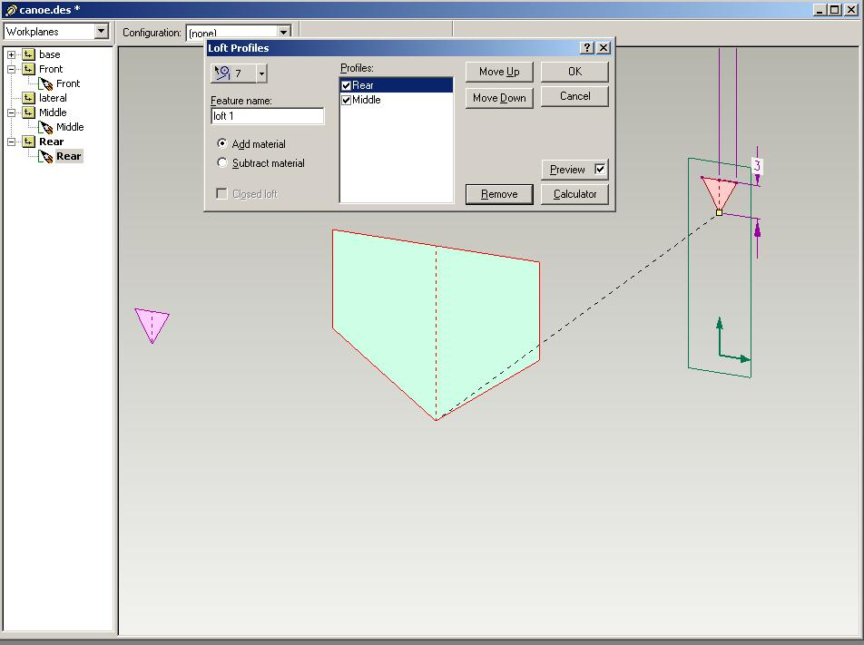
7 20. You can see from the three sketches above what the basic shape of our canoe will be. Using the Loft feature, you will pull (or extrude) material through these sketches to create the canoe shape. 21. Go to Features -> Loft through profile. The Active Sketch (in this case, the Rear sketch) is automatically included in the loft. 22. To add the other two sketches, Select Lines and lasso each sketch. See below:
8


9 23. Notice the dotted line that curves below the bottom points. The yellow box indicates the position of the loft flow on the Active Sketch. If the loft flow isn t like the one above, you may need to click on and move the yellow dot. If it looks like the one above, click OK. Your finished loft should look like the one below:

10 24. Finish your canoe by rounding edges and shelling it out (Shell Solids). ** Our canoe has no seats! Can you figure out a way to put a bench seat inside? **
Van Assembly. Creating an Assembly. Original by Steven Jaffe Modified by E. Brunelle 2/07 1
 Van Assembly Creating an Assembly 1 Part One the Axle 1. Set Units to Inches 2. Create a New Design. 3. Save the Design as axleinl_cad1_1 in your Van folder. 4. Create a New Sketch on the Lateral workplane.
Getting Started. Right click on Lateral Workplane. Left Click on New Sketch
 Getting Started 1. Open up PTC Pro/Desktop by either double clicking the icon or through the Start button and in Programs. 2. Once Pro/Desktop is open select File > New > Design 3. Close the Pallet window
Module 1G: Creating a Circle-Based Cylindrical Sheet-metal Lateral Piece with an Overlaying Lateral Edge Seam And Dove-Tail Seams on the Top Edge
 Inventor (10) Module 1G: 1G- 1 Module 1G: Creating a Circle-Based Cylindrical Sheet-metal Lateral Piece with an Overlaying Lateral Edge Seam And Dove-Tail Seams on the Top Edge In Module 1A, we have explored
Hydro Hull. Chapter 21. Boat. A. Save as "HYDRO". Step 1. Open your HULL MID PLANE file (Chapter 2).
.") Chapter 21 Boat Hydro Hull A. Save as "HYDRO". Step 1. Open your HULL MID PLANE file (Chapter 2). Step 2. Click File Menu > Save As. Step 3. Key-in HYDRO for the filename and press ENTER. B. Delete Loft1,
Chapter 21 Boat Hydro Hull A. Save as "HYDRO". Step 1. Open your HULL MID PLANE file (Chapter 2). Step 2. Click File Menu > Save As. Step 3. Key-in HYDRO for the filename and press ENTER. B. Delete Loft1,
Name: Date Completed: Basic Inventor Skills I
 Name: Date Completed: Basic Inventor Skills I 1. Sketch, dimension and extrude a basic shape i. Select New tab from toolbar. ii. Select Standard.ipt from dialogue box by double clicking on the icon. iii.
Drawing a Plan of a Paper Airplane. Open a Plan of a Paper Airplane
 Inventor 2014 Paper Airplane Drawing a Plan of a Paper Airplane In this activity, you ll create a 2D layout of a paper airplane. Please follow these directions carefully. When you have a question, reread
Bottom Rail. Chapter 2. Chair. A. Weldments Toolbar. Step 1. Click File Menu > New, click Part and OK. B. 3D Sketch.
 Chapter 2 Chair Bottom Rail A. Weldments Toolbar. Step 1. Click File Menu > New, click Part and OK. Step 2. Right click Sketch on the Command Manager toolbar and select Weldments, Fig. 1. Step 3. Click
From the above fig. After sketching the path and profile select the sweep command First select the profile from property manager tree And then select
 Chapter 5 In sweep command there is a) Two sketch profiles b) Two path c) One sketch profile and one path The sweep profile is used to create threads springs circular things and difficult geometry. For
Chair. Bottom Rail. on the Command Manager. on the Weldments toolbar.
 Chapter 2 Chair Bottom Rail A. Weldments Toolbar. Step 1. Click File Menu > New, click Part and OK. Step 2. Right click Sketch on the Command Manager toolbar and select Weldments, Fig. 1. Step 3. Click
Quick Start for Autodesk Inventor
 Quick Start for Autodesk Inventor Autodesk Inventor Professional is a 3D mechanical design tool with powerful solid modeling capabilities and an intuitive interface. In this lesson, you use a typical workflow
Module 1H: Creating an Ellipse-Based Cylindrical Sheet-metal Lateral Piece
 Inventor (10) Module 1H: 1H- 1 Module 1H: Creating an Ellipse-Based Cylindrical Sheet-metal Lateral Piece In this Module, we will learn how to create an ellipse-based cylindrical sheetmetal lateral piece
Inventor Activity 5: Lofted Vase
 Inventor Activity 5: Lofted Vase In this tutorial, you will use a few new commands to create a free form Lofted object. Sometimes you want to create an object that is not made up of square, flat, or perfectly
Cube in a cube Fusion 360 tutorial
 Cube in a cube Fusion 360 tutorial n Before using these instructions, it is helpful to watch this video screencast of the CAD drawing actually being done in the software. Click to link to the video tutorial.
Modeling Basic Mechanical Components #1 Tie-Wrap Clip
 Modeling Basic Mechanical Components #1 Tie-Wrap Clip This tutorial is about modeling simple and basic mechanical components with 3D Mechanical CAD programs, specifically one called Alibre Xpress, a freely
The Revolve Feature and Assembly Modeling
 The Revolve Feature and Assembly Modeling PTC Clock Page 52 PTC Contents Introduction... 54 The Revolve Feature... 55 Creating a revolved feature...57 Creating face details... 58 Using Text... 61 Assembling
Converting a solid to a sheet metal part tutorial
 Converting a solid to a sheet metal part tutorial Introduction Sometimes it is easier to start with a solid and convert it to create a sheet metal part. This tutorial will guide you through the process
Using Google SketchUp
 Using Google SketchUp Opening sketchup 1. From the program menu click on the SketchUp 8 folder and select 3. From the Template Selection select Architectural Design Millimeters. 2. The Welcome to SketchUp
Digital Camera Exercise
 Commands Used New Part This lesson includes Sketching, Extruded Boss/Base, Extruded Cut, Fillet, Chamfer and Text. Click File, New on the standard toolbar. Select Part from the New SolidWorks Document
Quick Start - ProDESKTOP
 Quick Start - ProDESKTOP Tim Brotherhood ProDESKTOP page 1 of 27 Written by Tim Brotherhood These materials are 2000 Staffordshire County Council. Conditions of use Copying and use of these materials is
Pull Down Menu View Toolbar Design Toolbar
 Pro/DESKTOP Interface The instructions in this tutorial refer to the Pro/DESKTOP interface and toolbars. The illustration below describes the main elements of the graphical interface and toolbars. Pull
Techniques for Troubleshooting Sketches &
 Techniques for Troubleshooting Sketches & Written by Tim Brotherhood These materials are 2001 PTC Conditions of use Copying and use of these materials is authorized only in the schools of teachers who
1. Creating geometry based on sketches 2. Using sketch lines as reference 3. Using sketches to drive changes in geometry
 4.1: Modeling 3D Modeling is a key process of getting your ideas from a concept to a read- for- manufacture state, making it core foundation of the product development process. In Fusion 360, there are
Module 2: Radial-Line Sheet-Metal 3D Modeling and 2D Pattern Development: Right Cone (Regular, Frustum, and Truncated)
") Inventor (5) Module 2: 2-1 Module 2: Radial-Line Sheet-Metal 3D Modeling and 2D Pattern Development: Right Cone (Regular, Frustum, and Truncated) In this tutorial, we will learn how to build a 3D model
Inventor (5) Module 2: 2-1 Module 2: Radial-Line Sheet-Metal 3D Modeling and 2D Pattern Development: Right Cone (Regular, Frustum, and Truncated) In this tutorial, we will learn how to build a 3D model
g. Click once on the left vertical line of the rectangle.
 This drawing will require you to a model of a truck as a Solidworks Part. Please be sure to read the directions carefully before constructing the truck in Solidworks. Before submitting you will be required
Pro/DESKTOP Tutorial Drafting Bow Compass
 Pro/DESKTOP Tutorial Drafting Bow Compass Michael Flowers 2005 1 Objectives: To develop confidence with the Pro/DESKTOP software. To learn to utilize extrude, project, revolve, round, and chamfer features.
Module 1C: Adding Dovetail Seams to Curved Edges on A Flat Sheet-Metal Piece
 1 Module 1C: Adding Dovetail Seams to Curved Edges on A Flat Sheet-Metal Piece In this Module, we will explore the method of adding dovetail seams to curved edges such as the circumferential edge of a
Shaft Hanger - SolidWorks
 ME-430 INTRODUCTION TO COMPUTER AIDED DESIGN Shaft Hanger - SolidWorks BY: DR. HERLI SURJANHATA ASSIGNMENT Submit TWO isometric views of the Shaft Hanger with your report, 1. Shaded view of the trimetric
Creating Van Drawings
 Creating Van Drawings Engineers create Drawings that manufacturers (and assemblers) use to make products. You are going to create Drawings in ProDESKTOP much like real engineers would for a product like
AutoDesk Inventor: Creating Working Drawings
 AutoDesk Inventor: Creating Working Drawings Inventor allows you to quickly and easily make quality working drawings from your 3D models. This tutorial will walk you through the steps in creating a working
Using Siemens NX 11 Software. The connecting rod
 Using Siemens NX 11 Software The connecting rod Based on a Catia tutorial written by Loïc Stefanski. At the end of this manual, you should obtain the following part: 1 Introduction. Start NX 11 and open
SolidWize. Online SolidWorks Training. Lofts: Tea Pot
 SolidWize Online SolidWorks Training Lofts: Tea Pot Step 1: Creating the Body Using inches as the unit, create the following sketch on the top plane. We will now add a plane above the top plane so that
SolidWorks Navigation
 SolidWorks Basics SolidWorks Navigation Command Bar Feature Tree Model Window Simple Box Select the Front plane Create a new sketch Create a Center Rectangle from the origin Smart Dimension the length
Inventor-Parts-Tutorial By: Dor Ashur
 Inventor-Parts-Tutorial By: Dor Ashur For Assignment: http://www.maelabs.ucsd.edu/mae3/assignments/cad/inventor_parts.pdf Open Autodesk Inventor: Start-> All Programs -> Autodesk -> Autodesk Inventor 2010
SolidWorks 95 User s Guide
 SolidWorks 95 User s Guide Disclaimer: The following User Guide was extracted from SolidWorks 95 Help files and was not originally distributed in this format. All content 1995, SolidWorks Corporation Contents
FUSION 360: SKETCHING FOR MAKERS
 FUSION 360: SKETCHING FOR MAKERS LaDeana Dockery 2017 MAKEICT Wichita, KS 1 Table of Contents Interface... 1 File Operations... 1 Opening Existing Models... 1 Mouse Navigation... 1 Preferences... 2 Navigation
Wireless Mouse Surfaces
 Wireless Mouse Surfaces Design & Communication Graphics Table of Contents Table of Contents... 1 Introduction 2 Mouse Body. 3 Edge Cut.12 Centre Cut....14 Wheel Opening.. 15 Wheel Location.. 16 Laser..
Introduction to Autodesk Inventor User Interface Student Manual MODEL WINDOW
 Emmett Wemp EDTECH 503 Introduction to Autodesk Inventor User Interface Fill in the blanks of the different tools available in the user interface of Autodesk Inventor as your instructor discusses them.
Made Easy. Jason Pancoast Engineering Manager
 3D Sketching Made Easy Jason Pancoast Engineering Manager Today I have taught you to sketch in 3D. It s as easy as counting ONE, TWO, FIVE...er...THREE! When your sketch only lives in Y and in X, Adding
WEEK 5: Shaft Modeling (C51X01, C51X02) Revolved Features, Chamfer
 Revolved Features, Chamfer") WEEK 5: Shaft Modeling (C51X01, C51X02) Revolved Features, Chamfer 1. Creating the Shaft Model 1. File> New> Part, Name: C51X01> OK 2. Insert> Revolve> Placement> Define> select TOP datum plane> Sketch
WEEK 5: Shaft Modeling (C51X01, C51X02) Revolved Features, Chamfer 1. Creating the Shaft Model 1. File> New> Part, Name: C51X01> OK 2. Insert> Revolve> Placement> Define> select TOP datum plane> Sketch
SolidWorks Design & Technology
 SolidWorks Design & Technology Training Course at PHSG Ex 5. Lego man Working with part files 8mm At first glance the Lego man looks complicated but I hope you will see that if you approach a project one
AEROPLANE. Create a New Folder in your chosen location called Aeroplane. The four parts that make up the project will be saved here.
 AEROPLANE Prerequisite Knowledge Previous knowledge of the following commands is required to complete this lesson. Sketching (Line, Rectangle, Arc, Add Relations, Dimensioning), Extrude, Assemblies and
SolidWorks Part I - Basic Tools SDC. Includes. Parts, Assemblies and Drawings. Paul Tran CSWE, CSWI
 SolidWorks 2015 Part I - Basic Tools Includes CSWA Preparation Material Parts, Assemblies and Drawings Paul Tran CSWE, CSWI SDC PUBLICATIONS Better Textbooks. Lower Prices. www.sdcpublications.com Powered
Clock Exercise (Inserting Planes)
") Clock Exercise (Inserting Planes) Prerequisite Knowledge To complete this exercise you will need to be familiar with Sketching, Applying relations, Extrude Boss/ Base, Extrude cut, Applying Textures, Renaming
Clock Exercise (Inserting Planes) Prerequisite Knowledge To complete this exercise you will need to be familiar with Sketching, Applying relations, Extrude Boss/ Base, Extrude cut, Applying Textures, Renaming
Lesson 6 2D Sketch Panel Tools
 Lesson 6 2D Sketch Panel Tools Inventor s Sketch Tool Bar contains tools for creating the basic geometry to create features and parts. On the surface, the Geometry tools look fairly standard: line, circle,
Table of Contents. Lesson 1 Getting Started
 NX Lesson 1 Getting Started Pre-reqs/Technical Skills Basic computer use Expectations Read lesson material Implement steps in software while reading through lesson material Complete quiz on Blackboard
Solidworks tutorial. 3d sketch project. A u t h o r : M. G h a s e m i. C o n t a c t u s : i n f s o l i d w o r k s a d v i s o r.
 Solidworks tutorial 3d sketch project A u t h o r : M. G h a s e m i C o n t a c t u s : i n f o @ s o l i d w o r k s a d v i s o r. c o m we will create this frame during the tutorial : In this tutorial
Model House Exercise-( Extrude)
") -( Extrude) Prerequisite knowledge Focus of the lesson Commands Used This lesson requires an understanding of using the sketch commands including Inserting a new sketch Adding sketch geometry Understanding
-( Extrude) Prerequisite knowledge Focus of the lesson Commands Used This lesson requires an understanding of using the sketch commands including Inserting a new sketch Adding sketch geometry Understanding
Lesson 10: Loft Features
 10 Goals of This Lesson Your students will be able to create the following part: profiles chisel This lesson plan corresponds to the Loft Features chapter of SolidWorks Getting Started. SolidWorks Student
10/14/2010. Chevy Malibu. Vehicle Design with Solidworks. Start SolidWorks Create a New SolidWorks Document. Miles, Rowardo B
 Chevy Malibu Vehicle Design with Solidworks Start SolidWorks Create a New SolidWorks Document Miles, Rowardo B 1 Click: Part and then OK Now you are ready to make a Part. 2 Right Toolbar: Document Properties:
Module 1E: Parallel-Line Flat Pattern Development of Sheet- Metal Folded Model Wrapping the 3D Space of An Oblique Circular Cylinder
 Inventor (10) Module 1E: 1E- 1 Module 1E: Parallel-Line Flat Pattern Development of Sheet- Metal Folded Model Wrapping the 3D Space of An Oblique Circular Cylinder In this Module, we will explore the topic
Kitchen and Bath Design Tutorial
 Kitchen and Bath Design Tutorial This tutorial continues where the Interior Design Tutorial left off. You should save this tutorial using a new name to archive your previous work. The tools and techniques
Introduction to Autodesk Inventor for F1 in Schools (Australian Version)
") Introduction to Autodesk Inventor for F1 in Schools (Australian Version) F1 in Schools race car In this course you will be introduced to Autodesk Inventor, which is the centerpiece of Autodesk s Digital
Introduction to Autodesk Inventor for F1 in Schools (Australian Version) F1 in Schools race car In this course you will be introduced to Autodesk Inventor, which is the centerpiece of Autodesk s Digital
J. La Favre Fusion 360 Lesson 5 April 24, 2017
 In this lesson, you will create a funnel like the one in the illustration to the left. The main purpose of this lesson is to introduce you to the use of the Revolve tool. The Revolve tool is similar to
1. Create a 2D sketch 2. Create geometry in a sketch 3. Use constraints to position geometry 4. Use dimensions to set the size of geometry
 2.1: Sketching Many features that you create in Fusion 360 start with a 2D sketch. In order to create intelligent and predictable designs, a good understanding of how to create sketches and how to apply
TOY TRUCK. Figure 1. Orthographic projections of project.
 TOY TRUCK Prepared by: Harry Hawkins The following project is of a small, wooden toy truck. This exercise will provide you with the procedure for constructing the various parts of the design then assembling
Alibre Design Tutorial - Simple Extrude Step-Pyramid-1
 Alibre Design Tutorial - Simple Extrude Step-Pyramid-1 Part Tutorial Exercise 4: Step-Pyramid-1 [text version] In this Exercise, We will set System Parameters first. Then, in sketch mode, outline the Step
On completion of this exercise you will have:
 Prerequisite Knowledge To complete this exercise you will need; to be familiar with the SolidWorks interface and the key commands. basic file management skills the ability to rotate views and select faces
< Then click on this icon on the vertical tool bar that pops up on the left side.
 Pipe Cavity Tutorial Introduction The CADMAX Solid Master Tutorial is a great way to learn about the benefits of feature-based parametric solid modeling with CADMAX. We have assembled several typical parts
SolidWorks Reference Geometry
 SolidWorks Reference Geometry IDeATe Laser Micro Part 2 Dave Touretzky and Susan Finger 1. Symmetry and Reference Geometry Today, you ll make this part bear-like face and then cut it on the laser cutter:
Hexagons for Art and Illusion Part II Get ready Start a new project FILE New Open Faced Cube Import the hexagon block LIBRARIES
 Hexagons for Art and Illusion Part II In our last lesson, we constructed the perfect hexagon using EasyDraw. We built a six pointed star, a solid faced cube, and put the cube inside the star. This lesson
MAKING THE FAN HOUSING
 Our goal is to make the following part: 39-245 RAPID PROTOTYPE DESIGN CARNEGIE MELLON UNIVERSITY SPRING 2007 MAKING THE FAN HOUSING This part is made up of two plates joined by a cylinder with holes in
Creo Revolve Tutorial
 Creo Revolve Tutorial Setup 1. Open Creo Parametric Note: Refer back to the Creo Extrude Tutorial for references and screen shots of the Creo layout 2. Set Working Directory a. From the Model Tree navigate
Feature-Based Modeling and Optional Advanced Modeling. ENGR 1182 SolidWorks 05
 Feature-Based Modeling and Optional Advanced Modeling ENGR 1182 SolidWorks 05 Today s Objectives Feature-Based Modeling (comprised of 2 sections as shown below) 1. Breaking it down into features Creating
Autodesk Inventor. In Engineering Design & Drafting. By Edward Locke
 Autodesk Inventor In Engineering Design & Drafting By Edward Locke Engineering Design Drafting Essentials Working Drawings: Orthographic Projection Views (multi-view, auxiliary view, details and sections)
The project focuses on the design for a Pencil holder, but could be adapted to any simple assembly.
 Introduction - Teacher Notes Fig 1. The project focuses on the design for a Pencil holder, but could be adapted to any simple assembly. Pro/DESKTOP enables pupils (and teachers) to communicate and model
Below are the desired outcomes and usage competencies based on the completion of Project 4.
 Engineering Design with SolidWorks Project 4 Below are the desired outcomes and usage competencies based on the completion of Project 4. Project Desired Outcomes: An understanding of the customer s requirements
Design & Technology in Schools Program. Space Exploration: A Pro/DESKTOP Teacher s Guide
 Design & Technology in Schools Program Space Exploration: A Pro/DESKTOP Teacher s Guide Space Exploration 2 Copyright 2003 Parametric Technology Corporation (PTC). All Rights Reserved. The PTC logo, Pro/DESKTOP
Create A Mug. Skills Learned. Settings Sketching 3-D Features. Revolve Offset Plane Sweep Fillet Decal* Offset Arc
 Create A Mug Skills Learned Settings Sketching 3-D Features Slice Line Tool Offset Arc Revolve Offset Plane Sweep Fillet Decal* Tutorial: Creating A Custom Mug There are somethings in this world that have
SolidWize. Online SolidWorks Training. Simple Sweep: Head Scratcher
 SolidWize Online SolidWorks Training Simple Sweep: Head Scratcher Step 1: Creating the Handle: Sketch Using Inches as the unit create a sketch on the Front plane. Start with the sketch shown below: Create
Toothbrush Holder. A drawing of the sheet metal part will also be created.
 Prerequisite Knowledge Previous knowledge of the following commands is required to complete this lesson; Sketch (Line, Centerline, Circle, Add Relations, Smart Dimension,), Extrude Boss/Base, and Edit
When you complete this assignment you will:
 Objjectiives When you complete this assignment you will: 1. sketch and create models using new work planes and the loft command. 2. sketch and create models using the revolve command. 3. sketch and dimension
Creo Parametric Primer
 PTC Creo Parametric - Primer Student and Academic Editions 02 Helpful hints are enclosed in red brackets or round bubbles like this one! Creo Parametric Primer THIS VERSION OF THE CREO PRIMER HAS BEEN
Solid Part Four A Bracket Made by Mirroring
 C h a p t e r 5 Solid Part Four A Bracket Made by Mirroring This chapter will cover the following to World Class standards: Sketch of a Solid Problem Draw a Series of Lines Finish the 2D Sketch Extrude
Kitchen and Bath Design Tutorial
 Kitchen and Bath Design Tutorial This tutorial continues where the Interior Design Tutorial left off. You should save this tutorial using a new name to archive your previous work. The tools and techniques
Lesson 4 Holes and Rounds
 Lesson 4 Holes and Rounds 111 Figure 4.1 Breaker OBJECTIVES Sketch arcs in sections Create a straight hole through a part Complete a Sketched hole Understand the Hole Tool Use Info to extract information
Introduction to Circular Pattern Flower Pot
 Prerequisite Knowledge Previous knowledge of the sketching commands Line, Circle, Add Relations, Smart Dimension is required to complete this lesson. Previous examples of Revolved Boss/Base, Cut Extrude,
Engineering Technology
 Engineering Technology Introduction to Parametric Modelling Engineering Technology 1 See Saw Exercise Part 1 Base Commands used New Part This lesson includes Sketching, Extruded Boss/Base, Hole Wizard,
Activity 5.5a CAD Model Features Part 1
 Activity 5.5a CAD Model Features Part 1 Introduction In order to use CAD effectively as a design tool, the designer must have the skills necessary to create, edit, and manipulate a 3D model of a part in
Spreadsheets 3: Charts and Graphs
 Spreadsheets 3: Charts and Graphs Name: Main: When you have finished this handout, you should have the following skills: Setting up data correctly Labeling axes, legend, scale, title Editing symbols, colors,
Conquering the Rubicon
 Autodesk Inventor R10 Fundamentals: Conquering the Rubicon Elise Moss SDC PUBLICATIONS Schroff Development Corporation www.schroff.com www.schroff-europe.com Schroff Development Corporation P.O. Box 1334
EQ7 Summer Drawing Series: Block 4
 EQ7 Summer Drawing Series: Block 4 www.doyoueq.com/blog Welcome to the Block 4 post for the EQ7 Summer Drawing Series! It s the last block in this drawing+sewing series and I hope you ve learned a lot
Alternatively, the solid section can be made with open line sketch and adding thickness by Thicken Sketch.
 Sketcher All feature creation begins with two-dimensional drawing in the sketcher and then adding the third dimension in some way. The sketcher has many menus to help create various types of sketches.
Part 8: The Front Cover
 Part 8: The Front Cover 4 Earpiece cuts and housing Lens cut and housing Microphone cut and housing The front cover is similar to the back cover in that it is a shelled protrusion with screw posts extruding
Product Modelling in Solid Works
 Product Modelling in Solid Works In the following exercise you will use solid works to construct the computer mouse shown opposite. In this exercise you will use a number of advanced features to achieve
Batch Processing Converting images in a folder to JPEG
 Batch Processing Converting images in a folder to JPEG Request I would like to convert multiple RAW images (NEF files) to JPEG images all at once Response You can use a Batch Process to convert all RAW
This project covers the following design concepts:
 Design Project 5 This project covers the following design concepts: DRAWING TOOLS REGIONS SURFACES ADJUSTING DEPTH & HEIGHT CONSTRAINTS & ATTACHMENTS CARVING LIST MERGE MANAGING DATA UPLOADING TO MEMORY
Introduction to Sheet Metal Features SolidWorks 2009
 SolidWorks 2009 Table of Contents Introduction to Sheet Metal Features Base Flange Method Magazine File.. 3 Envelopment & Development of Surfaces.. 14 Development of Transition Pieces.. 23 Conversion to
Beginner s Guide to SolidWorks Alejandro Reyes, MSME Certified SolidWorks Professional and Instructor SDC PUBLICATIONS
 Beginner s Guide to SolidWorks 2008 Alejandro Reyes, MSME Certified SolidWorks Professional and Instructor SDC PUBLICATIONS Schroff Development Corporation www.schroff.com www.schroff-europe.com Part Modeling
Geometer s Sketchpad Version 4
 Geometer s Sketchpad Version 4 For PC Name: Date: INVESTIGATION: The Pythagorean Theorem Directions: Use the steps below to lead you through the investigation. After each step, be sure to click in the
Copyrighted. Material. Copyrighted. Material. Copyrighted. Material. Copyrighted. Material
 ENGINEERING & COMPUTER GRAPHICS WORKBOOK Using SolidWorks 2005 Ronald E. Barr Thomas J. Krueger Theodore A. Aanstoos Davor Juricic SDC PUBLICATIONS Schroff Development Corporation www.schroff.com www.schroff-europe.com
Architecture 2012 Fundamentals
 Autodesk Revit Architecture 2012 Fundamentals Supplemental Files SDC PUBLICATIONS Schroff Development Corporation Better Textbooks. Lower Prices. www.sdcpublications.com Tutorial files on enclosed CD Visit
for Solidworks TRAINING GUIDE LESSON-9-CAD
 for Solidworks TRAINING GUIDE LESSON-9-CAD Mastercam for SolidWorks Training Guide Objectives You will create the geometry for SolidWorks-Lesson-9 using SolidWorks 3D CAD software. You will be working
Introduction to Revolve - A Glass
 Introduction to Revolve - A Glass Design & Communication Graphics 1 Object Analysis sheet Design & Communication Graphics 2 Prerequisite Knowledge Previous knowledge of the following commands are required
Introduction to solid modeling using Onshape
 Onshape is a CAD/solid modeling application. It provides powerful parametric and direct modeling capabilities. It is cloud based therefore you do not need to install any software. Documents are shareable.
ME Week 2 Project 2 Flange Manifold Part
 1 Project 2 - Flange Manifold Part 1.1 Instructions This project focuses on additional sketching methods and sketching commands. Revolve and Work features are also introduced. The part being modeled is
Engineering & Computer Graphics Workbook Using SolidWorks 2014
 Engineering & Computer Graphics Workbook Using SolidWorks 2014 Ronald E. Barr Thomas J. Krueger Davor Juricic SDC PUBLICATIONS Better Textbooks. Lower Prices. www.sdcpublications.com Powered by TCPDF (www.tcpdf.org)
1. Open the Feature Modeling demo part file on the EEIC website. Ask student about which constraints needed to Fully Define.
 BLUE boxed notes are intended as aids to the lecturer RED boxed notes are comments that the lecturer could make Control + Click HERE to view enlarged IMAGE and Construction Strategy he following set of
Assembly Receiver/Hitch/Ball/Pin to use for CAD LAB 5A and 5B:
 MECH 130 CAD LAB 5 SPRING 2017 due Friday, April 21, 2016 at 4:30 PM All of LAB 5 s hardcopies will be working drawing layouts. Do not print out from the part file. We will be using the ME130DRAW drawing