[Q] DEFINE AUDIO AMPLIFIER. STATE ITS TYPE. DRAW ITS FREQUENCY RESPONSE CURVE.
|
|
|
- Damon Bennett
- 5 years ago
- Views:
Transcription
1 TOPIC : HI FI AUDIO AMPLIFIER/ AUDIO SYSTEMS INTRODUCTION TO AMPLIFIERS: MONO, STEREO DIFFERENCE BETWEEN STEREO AMPLIFIER AND MONO AMPLIFIER. [Q] DEFINE AUDIO AMPLIFIER. STATE ITS TYPE. DRAW ITS FREQUENCY RESPONSE CURVE. An audio power amplifier is an electronic amplifier that increase the strength of low-power audio signals (signals composed primarily of frequencies between Hz, the human range of hearing) to a level suitable for driving loudspeakers. It is the final electronic stage in a typical audio playback chain. Types of Audio systems : Mono Amplifier system Stereo Amplifier system
2 [Q] : COMPARE STEREO AMPLIFIER WITH MONO AMPLIFIER
3 BLOCK DIAGRAM OF HI FI AMPLIFIER AND ITS WORKING. CONTROLS AVAILABLE ON IT AND THEIR FUNCTION, [Q] WHAT IS HI-FI SYSTEM? LIST CHARACTERISTICS OF HI-FI SYSTEM. The word fidelity means faithfulness. In audio system it is used to indicate faithful reproduction of sound. Hi-Fi system stands for high fidelity stereophonic reproducing system. Such a Hi- Fi Sound can be obtained from the recorded stereo tape or live systems from the microphones. High fidelity reproduction is essentially sound reproduction such that the most critical person can listen intensity to it without any distortion. Characteristics of HI-FI amplifier: 1. Signal to noise ratio should be better than 50dB. 2. Frequency response should be flat within +-1dB. 3. Non-linear distortion should not be more than 1%. 4. The system should possess dynamic range of atleast 8dB. 5. Stereophonic effect should be provided. 6. Environmental conditions should be such as to eliminate the external noise in listening room. [Q] DRAW AND DESCRIBE THE BLOCK DIAGRAM OF HI-FI AMPLIFIER. Figure shows the block diagram of a high-fidelity stereo reproducing system. High- fidelity sound can be obtained from the recorded stereo tape or in live system from the microphones. (Stereo signal can also be obtained from the record player.) The stereo signal is fed to two independent amplification channels through a tapemic switch. The amplifier system consist of a low noise high gain preamplifier, equalizer, well design amplifiers giving flat frequency response and little distortion by using negative feedback circuit and then the matching transformer.(a balancing circuit is incorporated to balance out any imbalance in the characteristics of otherwise identical circuits.) The secondary of the matching transformer of each channel is connected to the respective loudspeaker column. For Hi-fi, the loudspeaker columns consisting of woofer, squawker and tweeter are used. All the blocks are design so as to get fat frequency response (from 40 to 15000Hz), little distortion (less than 1%), high signal-to-noise ratio (more than 50db) and high dynamic range (100 db) to achieve the final output of high fidelity.
4 Balance control: Two amplifiers of a stereo system, although independent of each other are built as matched pair to give equal output for the same input. In spite of the two amplifiers being identical, there may be variations in the characteristics of transistors and ICs and positioning of loudspeakers and furnishings with respect to the listener. The circuit used to compensate for such variations are called Balance control. Loudness control: Sometime music is at low level of volume (as in case of the background music). At low levels there is considerable loss in bass in reproduction. It is therefore, necessary that there should be substantial boosting of the bass at low levels. Boosting at treble may be only nominal because loss at high notes is quite small. The control which provides desired big boosting at bass and a little boosting at treble is called loudness control. Bass and Treble control: It is provided to tailor bass treble as per personal taste of the listener. Master Gain control: a master gain control is used for adjusting overall volume without disturbing the balance. This is achieved by using dual concentric shafts,
5 the inner shaft adjust the balance control and the outer shaft, the overall gain or volume of the amplifier. A typical master gain control circuit is shown in figure is adjusted for balancing the two channels and then R2 and R3 are adjusted for increasing or decreasing the volume of the channels. R2 and R3 are ganged. Blend control: The stereo effect is diluted by this control when it is too much leftright effect. Diluting is done by disbalancing the two channels. It is shown in figure. Blend control potentiometer is set at zero resistance for balance output. For disturbing the balance, this is advanced further to reduce gain of the left channel. Although blending can be done by balance control also, but once set, the balanced control is not disturbed. Quasi stereo switch: When any one channel signal is made to go into both the channels, one can use both channels and their speakers for a monophonic source of signal. This is done by a switch called quasi-stereo switch. [Q] EXPLAIN THE FUNCTION OF FOLLOWING IN HI-FI AMPLIFIER: I)BALANCE CONTROL II)LOUDNESS CONTROL III)BASS AND TREBLE CONTROL IV)QUASI STABLE SWITCH. Controls available on Hi-Fi system are :- Balance control :- Inspite of the two amplifiers being identical, there may be variations in the output of each channel due to variation in the characteristic of transistors and ICs and positioning of loudspeaker and furnishing with respect to the listener. The circuit used to compensate for such variation is called Balance Control When the balance control is moved down, the output of left channel will increase while that of the right one will decrease, and vice versa when moved up. Loudness control :- Sometimes music is at low level of volume (as in case of the background music). At low levels there is considerable loss in bass in reproduction. It is therefore, necessary that there should be substantial boosting of bass at low levels. Boosting at treble may be nominal because loss at high note is quite small. The control which provides desired big boosting at bass and a little boosting at treble is called Loudness control. It boost audio by +12 db at 50Hz and +3 db at 10Khz. Such a volume control also act as loudness control and is known as Contour Control.
6 Bass and treble control :- It is provided to tailor bass and treble as per personal taste of the listener. Quasi stereo switch :- This causes any one channel signal to go into all channels. This way, one can use all channels and all speakers for a monophonic source of signal [Q] LIST VARIOUS CONTROL OF HI-FI AMPLIFIER AND EXPLAIN ANY ONE Ans:- Various control of Hi-Fi amplifier:- 01M Balance Control: Master Gain Control: Blend Control: Quasi Stereo Switch: Bass & Treble Control: Loudness Control: Balance Control: Two amplifiers of a stereo system, although independent of each other, are built as matched pair to give equal output for the same input. In spite of the two amplifiers being identical, there may be variations in the output of each channel due to variations in the characteristics of transistors & ICs and positioning of loudspeaker & furnishing with respect to the listener. The circuit used is called BALANCE CONTROL. A simple circuit is shown in fig. The balance control is a potentiometer. When it is set in the center, the current through LED1 & LED2 should be identical, if the signals in the left & right channels are equal. In that case both LED will be equally bright. In case of any inequality, the two brightness level will also become unequal. When balance control is moved down, the output of the left channel will increase while that of right one will decrease, and vice-versa when moved up.
7 Master Gain Control: A master gain control is used for adjusting overall volume without disturbing the balance. This is achieved by using dual concentric shafts, the inner shaft adjusts the balance control & the outer shaft, the overall gain or volume of the amplifier. A typical master gain control circuit is shown above. R1 is adjusted for balancing two channels & then R2 & R3 are adjusted for increasing or decreasing the volume of the channels. R2 & R3 are ganged Blend Control: The stereo effect is diluted by this control when there is too much left-right effect. Diluting is done by misbalancing the two channels. It is shown in fig. above; blend control potentiometer is set at zero resistance for balanced output. For disturbing the balance, this is advanced further to reduce gain of the left channel. Although blending can be done by balance control also, but once set, the balance control is not disturbed. Quasi Stereo Switch: When any one channel signal is made to go into both the channels, one can use both channels & their speakers for monophonic source of signal. This is done by a switch called quasi-stereo switch. Bass & Treble Control: It is provided to tailor bass & treble as per personal taste of listener. Loudness Control: Sometimes music is at low level of volume. At low levels there is considerable loss in bass in reproduction. It is, therefore necessary that there should be substantial boosting of bass at low levels. Boosting at treble may be only nominal because loss at high notes is quite small. The control which provides desired boosting at bass & at treble is called LOUDNESS CONTROL.
8 It boost audio by +12dB at 50Hz & +3dB at 10 KHz. The loudness control should be used only when sound level is low
9 GRAPHIC EQUALIZER CONCEPT- CIRCUIT DIAGRAM AND OPERATION. (5-POINT CIRCUIT DIAGRAM) WHAT IS THE GRAPHIC EQUALIZER? WRITE ITS NECESSITY Graphic Equalizer: A graphic equalizer is a high-fidelity audio control that allows the user to see graphically and control individually a number of different frequency bands in a stereophonic system. A typical graphic equalizer consists of several audio filter/amplifiers, each centered at a specific frequency in the audio range. Most graphic equalizers have two identical sets of filter/amplifiers, one for each channel in a stereophonic system. The gain (volume) controls in most graphic equalizers are slide potentiometers that are adjusted by moving a control button up or down. Gain is increased by sliding the button upwards. The slide potentiometers for each channel are placed side-by-side, with the lowest-frequency unit at the left and the highest-frequency unit at the right. In this way, the positions of the buttons appear to follow a graphical curve that represents the gain as a function of frequency for each channel.
![[Q] DRAW AND DESCRIBE OPERATION OF GRAPHIC EQUALIZER [1] In five point configuration, the graphic equalizer breaks up an audio input signal into five different bands covering the range of human](/docs-images/86/94105671/images/10-0.jpg "hearing. Once this is completed, the signal in each band can be adjusted to provide best sound.")
10 [Q] DRAW AND DESCRIBE OPERATION OF GRAPHIC EQUALIZER [1] In five point configuration, the graphic equalizer breaks up an audio input signal into five different bands covering the range of human hearing. Once this is completed, the signal in each band can be adjusted to provide best sound. [1]A : The center frequencies f1, f2, f3, f4 and f5 of the frequency bands of the graphic equalizer are usually fixed at pre-set values. Once these bands are added back together, they are passed through an amplifier which increases the amplitude of the signal to the point where there is enough power that can be heard through an ordinary speaker. [2] The circuit diagram of graphic equalizer is shown in figure. The graphic equalizer consists of an amplifier for every segment of octave band. Such amplifiers are connected in parallel to cover the complete frequency range. [3] The individual gains of these amplifiers are adjusted such that the required frequency response is obtained. Using five amplifiers for five octaves of frequency may be very expensive. Hence amplifier shown in figure is normally used.
11 The figure shows, there is only one amplifier with multiple feedback paths. There are gain controls and LC tuned circuits in every feedback path. Thus the gain of every octave band is separately adjusted by the corresponding feedback path gain. [4] The center frequency of the octave band is selected by inductors L1, L2, L3, L4 and L5. The gains of individual octave bands are adjusted by potentiometer controls in the feedback path. [5] The combination of individual control setting for various octaves will provide the required frequency response. The peaks at individual octave bands overlap each other. Hence, phasing distortion needs to be avoided. This distortion occurs due to interaction between the overlapping peaks. The slider controls of each octave band can boost or cut the signals from +15 db to 15 db. [Q] STATE AND EXPLAIN THE CONCEPT OF GRAPHIC EQUALIZERS. Graphic equalizer is used to eliminate unwanted peaks in the frequency response of audio systems. In five point configuration, the graphic equalizer breaks up an audio input signal into five different bands covering the range of human hearing. Once this is completed, the signal in each band can be adjusted to provide best sound. The center frequencies f1, f2, f3, f4 and f5 of the frequency bands of the graphic equalizer are usually fixed at pre-set values. Once these bands are added back together, they are passed through an amplifier which increases the amplitude of the signal to the point where there is enough power that can be heard through an ordinary speaker. The graphic equalizer consists of an amplifier for every segment of octave band. Such amplifiers are connected in parallel to cover the complete frequency range. The individual gains of these amplifiers are adjusted such that the required frequency response is obtained. Using five amplifiers for five octaves of frequency may be very expensive.
![DOLBY NR RECORDING SYSTEM [Q] EXPLAIN DOLBY-NR RECORDING SYSTEM IN BRIEF. [1] The Name Dolby is synonymous with Noise-Reduction Systems.(Here Nr represents for Noise-reduction). [2] Dr.](/docs-images/86/94105671/images/12-1.jpg "Ray Dolby introduced a novel system so the name given. [3] In practice, Dolby system is used for pre-emphasis of high notes and deemphasis of low notes by equalization.")
12 DOLBY NR RECORDING SYSTEM [Q] EXPLAIN DOLBY-NR RECORDING SYSTEM IN BRIEF. [1] The Name Dolby is synonymous with Noise-Reduction Systems.(Here Nr represents for Noise-reduction). [2] Dr. Ray Dolby introduced a novel system so the name given. [3] In practice, Dolby system is used for pre-emphasis of high notes and deemphasis of low notes by equalization. Dolby system provides db improvement in SNR. [4] In his system, weak signals below 40 db, above noise are boosted before recording. All signals which are 40 db or higher, pass through Dolby system direct without change. [5] Signal in the absence of boosting is shown in Fig.(a) After boosting,recording noise remains unchanged but signal is boosted as shown in fig(b).during playback, signal and nose both are reduced as shown in fig(c).
13 DOLBY A SYSTEM: fig : Reduction of Noise by 10 db in Dolby System Boosting is done in 4 bands 1) Below 80 Hz. 2) 80 Hz to ) 3 khz and above. 4).9 khz and above. Bands 3 and 4 overlap above 9 khz, so that the high frequency noise, in the form of hissing sound is considerably reduced. Each frequency band is processed separately by using low pass, band pass and high pass filters and limiters. Dolby B System: [1] Amore simplified system than Dolby A system has been developed for home use and is known as Dolby B System. [2] In Dolby-B system, the encoded signal covers a signal frequency band from 500 Hz upwards. [3]Signal below a specified threshold value in level are pass through a variable filter which increases the level by about 1 db at 500 Hz. Curve shown by dotted line as shown in fig.

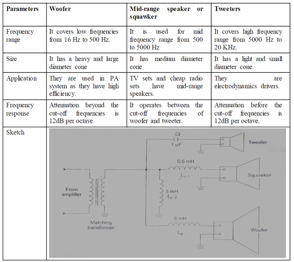
14 The processed signal from the variable filter and the direct input signal are added. The adder gives the Dolby output. For playback, the signal is inverted and fed to the variable filter. The output of the filter gives to the adder to give decoded output. TYPES OF SPEAKER WOOFER, MID-RANGE, TWEETER Compare between woofer, tweeter and squawker on the basis of following parameters. i) Frequency response ii) Cross over network iii) Cost iv) Application
15
16 CROSS OVER NETWORK CIRCUIT AND ITS FUNCTION [Q] STATE THE NECESSITY OF CROSS OVER NETWORK. Necessity of Cross over Network [1] A single cone type speaker is not able to provide uniform response and adequate output power over the entire AF range. [2]A loudspeaker mechanism with a heavy and large diameter called woofer can reproduce low frequencies. [3]A loudspeaker with a light and small diameter cone known as tweeter which performs much better at the high frequency audio frequency range. [4] For proper functioning of a dual speaker system, it is necessary that the frequency range to be covered by the combination of speakers should be split into two ranges at a frequency called cross-over frequency. [5] Hence woofers & tweeters are used with cross-over networks, for getting a uniform frequency response over the entire frequency range [Q] DRAW THE CIRCUIT DIAGRAM OF CROSS OVER NETWORK AND EXPLAIN ITS OPERATION IN BRIEF. When a multiway loudspeaker system is used to get flat frequency response for the entire range of audio frequencies, it is essential to have a crossover network to divide the incoming signal into separate frequency ranges for each speaker. In the absence of crossover networks, the speakers will suffer overheating and the output will be distorted when full power at frequencies outside their range is fed to them. The overall efficiency will be much reduced in the absence of crossover networks. Crossover networks make use of the fact that the capacitive reactance decreases with increase in frequency [ X 2 1 FC increase in frequency (X1= 2 f L). A basic crossover network is illustrated in fig. ]and the inductive reactance increases with

 is shown in Fig.")
17 The circuit consists of a low-pass LC filter across the woofer and a frequencies (16 Hz to 1000 Hz) to go to the woofer. The series reactance of L and shunt reactance of C for high audio frequencies prevents these frequencies from going to the woofer. The high-pass filter consisting of C in series and L in shunt allows the high audio frequencies to pass to the tweeter and blocks the low frequencies. The response curve of a typical crossover network (of Fig ) is shown in Fig.. It gives an attenuation of 12 db per octave

![VALUES OF L AND C [Q] DRAW THE THREE WAY](/docs-images/86/94105671/images/18-1.jpg "CROSS OVER N/W WITH ITS FREQUENCY")
18 CIRCUIT DIAGRAM AND FREQUENCY RESPONSE OF THREE-WAY CROSS OVER NETWORKGIVE THE VALUES OF L AND C [Q] DRAW THE THREE WAY CROSS OVER N/W WITH ITS FREQUENCY RESPONSE GRAPH
19 Where, R1 is the impedance of a loudspeaker in ohms and fc is the crossover frequency in Hz, L is The inductance and C, the capacitance of LC circuits. A commercial three-way divider network is shown in Fig. In this circuit the capacitor C1 of 1μF in series with the tweeter prevents low and mid-frequencies from reaching the tweeter. Similarly, the inductance Lw of 5 mh in series with the woofer prevents high frequencies from reaching the woofer. Inductances Ls1 and Ls2 of 0.5 mh and 5 mh, respectively in the squawker circuit allow only mid-frequencies and prevent too low and too high frequencies from reaching the squawker. A typical divider curve for a three-way network of Fig. is shown in Fig. A single element in filtering gives attenuation of 6 db per octave and double element in filtering gives attenuation of 6 db per octave and double elements give 12 db octave.
20 PUBLIC ADDRESS SYSTEM: NEED AND USE, BLOCK DIAGRAM, REQUIREMENTS OF A PUBLIC ADDRESS SYSTEM [Q] EXPLAIN DETAIL PUBLIC ADDRESS SYSTEM WITH SCHEMATIC BLOCK DIAGRAM. A public address system (PA system) is an electronic sound amplification and distribution system with a microphone, amplifier and loudspeaker. The intensity of sound decrease with the distance to receive good intensity of sound for comfortable listening. The system fulfils this function is called public address system. Or simply PA system. BLOCK DIAGRAM :- It is an electronics system in which converts into electrical signal by microphone. The electrical audio signals are amplified and fed into another transducer the loudspeaker which converts the audio signals into the sound wave. The block diagram consist :- Microphone Mixer Voltage amplifier Processing circuit Driver amplifier Power amplifier Loud speaker Microphone:-
21 It is a electrical transducer it pick up sound wave and converts into the electrical variations called audio signal. Mixer :- The output of the microphone is fed into the mixer stage. the mixer stage is to effectively isolate different channels from each other before feeding into the main amplifier. Voltage amplifier :- It further amplifies the output of the mixer. rocessing Circuit :- These circuit have master gain control and the tone controls Driver amplifier :- It is gives voltage amplification to the signal to such an extent that when fed to the next stage the internal resistance of that stage is reduced. Power amplifier :- it is gives desired power amplification to the signal. it is push-pull type of circuit in general. the power amplifier connected to the loudspeaker. Loudspeaker:- It converts electrical audio signal into pressure variation resulting in sound.
22 Requirements Sounds from the loudspeaker should not reach the microphone, as a acoustic feedback will result in a loud howling sound. Distribution of sound intensity :- Loudness of the sound is contained in low notes and the intelligibility in high notes. As high notes suffer grater attenuation with distance than the low note intelligibility suffers at further distance. Reverberation :- In a reverberation medium the intelligibility is poor. The Pa system should throw additional power in those areas where the direct gets submerged in the echoes. Dynamic Range Limitation:- The amplifier of a good PA system is equipped with a level limiter which keeps the output level constant when the input level exceeds a certain predetermined value. Matching :- Matching of the loudspeaker impedance with the output impedance of the amplifier is necessary for maximum transfer of energy from amplifier to loudspeaker. Grounding :- Chassis and shields of equipments and coaxial cables should be properly earthed through water pipes Audio systems
23
Sound recording & playback
 Sound recording & playback Dynamic microphone Condenser microphone Carbon microphone Frequency response curves Sound recording Amplifiers Loudspeakers Sound recording & playback - 1 Dynamic microphone
How to Connect a Three-Way (Six Speaker) Legatia Speaker System to a 4-Channel Amplifier in a Quasi-Active Crossover Configuration
 Legatia Speaker System to a 4-Channel Amplifier in a Quasi-Active Crossover Configuration") How to Connect a Three-Way (Six Speaker) Legatia Speaker System to a 4-Channel Amplifier in a Quasi-Active Crossover Configuration Hybrid Audio Technologies highly recommends the use of active crossovers
How to Connect a Three-Way (Six Speaker) Legatia Speaker System to a 4-Channel Amplifier in a Quasi-Active Crossover Configuration Hybrid Audio Technologies highly recommends the use of active crossovers
Sound Design and Technology. ROP Stagehand Technician
 Sound Design and Technology ROP Stagehand Technician Functions of Sound in Theatre Music Effects Reinforcement Music Create aural atmosphere to put the audience in the proper mood for the play Preshow,
Learning Objectives:
 Learning Objectives: At the end of this topic you will be able to; recall the conditions for maximum voltage transfer between sub-systems; analyse a unity gain op-amp voltage follower, used in impedance
EQ s & Frequency Processing
 LESSON 9 EQ s & Frequency Processing Assignment: Read in your MRT textbook pages 403-441 This reading will cover the next few lessons Complete the Quiz at the end of this chapter Equalization We will now
High-definition sound processor
 High-definition sound processor The BA3884F and BA3884S are sound processor ICs that perform phase and harmonic compensation on audio signals to accurately reproduce the rise section of audio signals that
USER GUIDE PREFIX PREMIUM STEREO ONBOARD BLENDER
 www.fishman.com USER GUIDE PREFIX PREMIUM STEREO ONBOARD BLENDER Welcome Thank you for making Fishman a part of your acoustic experience. We are proud to offer you the finest acoustic amplification products
Professional Equalizer-Preamp Suitable for Home Use
 A combined Professional Equalizer-Preamp Suitable for Home Use KENNETH W. BETSH* Designed originally for broadcast-station use, this preamplifier can be adapted to any installation where it would be desirable
From time to time it is useful even for an expert to give a thought to the basics of sound reproduction. For instance, what the stereo is all about?
 HIFI FUNDAMENTALS, WHAT THE STEREO IS ALL ABOUT Gradient ltd.1984-2000 From the beginning of Gradient Ltd. some fundamental aspects of loudspeaker design has frequently been questioned by our R&D Director
High-definition sound processor
 High-definition sound processor The is a sound processor IC that performs phase and harmonic compensation on audio signals to accurately reproduce the rise section of audio signals that determines the
AS Electronics Project: 3-Channel Sound-to-Light Display
 : 3-Channel Sound-to-Light Display By 1. Contents 1. CONTENTS...2 2. AIM...3 3. SPECIFICATION...3 4. POSSIBLE SOLUTIONS...4 4.1. FILTERS...4 4.2. RECTIFIERS...4 5. CHOSEN SOLUTION...5 5.1. BUFFER...5 5.2.
30 Watt Audio Power Amplifier
 30 Watt Audio Power Amplifier Including Preamp, Tone Controls, Reg dc Power Supply, 18 Watt into 8 Ohm - 30W into 4 Ohm loads Amplifier Section Circuit diagram: Audio Power Amplifier Circuit Diagram This
Lab 10 - INTRODUCTION TO AC FILTERS AND RESONANCE
 159 Name Date Partners Lab 10 - INTRODUCTION TO AC FILTERS AND RESONANCE OBJECTIVES To understand the design of capacitive and inductive filters To understand resonance in circuits driven by AC signals
Sound Quality. Crossovers. High-Precision Stereo 2-Way/3-Way/ Mono 4-Way Crossover with Limiters, Adjustable Time Delays and CD Horn Correction
 Professional stereo 2-way/3-way/ mono 4-way crossover featuring state-of-the-art Linkwitz-Riley filters with 24 db/octave Individual Limiters on each output for optimal loudspeaker protection Adjustable
USERS MANUAL EBS MICROBASSII BLACK LABEL SERIES. EBS MicroBassII. EBS Professional Bass Equipment SPECIFICATIONS
 SPECIFICATIONS Nominal Input Level - 8 dbv Input Impedance 10 Mohms (Ch A), 1 Mohms (Ch B) Output Impedance 10 kohms Frequency Response +0 / -3 db 20 20 khz Tone Controls Bass +/- 15 db @ 100 Hz Treble
Before You Start. Program Configuration. Power On
 StompBox is a program that turns your Pocket PC into a personal practice amp and effects unit, ideal for acoustic guitar players seeking a greater variety of sound. StompBox allows you to chain up to 9
Our Mailing and Shipping Address:
 5 January 2005 This contact update page has been added to the Acrobat document you have downloaded. Please disregard any contact information printed within the document. Our Mailing and Shipping Address:
EXOS TM. User s Manual. Electronic Crossover for the STATEMENT. Electrostatic Hybrid High Resolution Loudspeaker System. electronic crossover
 EXOS TM User s Manual Electronic Crossover for the STATEMENT e v o l u t I o n 2 Electrostatic Hybrid High Resolution Loudspeaker System electronic crossover -8-4 0 4 balanced on 50Hz CONTOUR db MUTE BASS
ONLINE TUTORIALS. Log on using your username & password. (same as your ) Choose a category from menu. (ie: audio)
 Choose a category from menu. (ie: audio)") ONLINE TUTORIALS Go to http://uacbt.arizona.edu Log on using your username & password. (same as your email) Choose a category from menu. (ie: audio) Choose what application. Choose which tutorial movie.
ONLINE TUTORIALS Go to http://uacbt.arizona.edu Log on using your username & password. (same as your email) Choose a category from menu. (ie: audio) Choose what application. Choose which tutorial movie.
DIY: from vinyl to compact disk
 AUDIO & HI-FI DIY: from vinyl to compact disk with a PC and sound card Nowadays, with the availability of personal computers and compact-disk (CD) writers, there is nothing in the way of transferring one
Stereo 3-Way Active Crossover User Manual Model K231 Sublime Acoustic, LLC
 Stereo 3-Way Active Crossover User Manual Model K231 Sublime Acoustic, LLC Features Stereo 3-way Active Crossover for driving separate subwoofer, midrange and tweeter amplifiers Linkwitz-Riley crossover
π Speakers Crossover Electronics 101
 π Speakers Crossover Electronics 101 Overview 1. Resistors - Ohms Law Voltage Dividers and L-Pads 2. Reactive components - Inductors and Capacitors 3. Resonance 4. Peaking 5. Damping Formulas Ohm s Law
PA System in a Box. Edwin Africano, Nathan Gutierrez, Tuan Phan
 PA System in a Box Edwin Africano, Nathan Gutierrez, Tuan Phan Overview A public address system (PA System) is an electronic sound distribution system that allows music and speech to reach a large amount
The Future of Sound. Made Perfectly Clear.
 JK DI-Boxes User Guide JK1 - Active DI BOX JK2 - Stereo DI BOX JKA - Acoustic DI BOX JKP - Passive DI BOX JKT - Tone Generator The Future of Sound. Made Perfectly Clear. At KV2 Audio our vision is to constantly
TECHNICAL WHITE PAPER THE BENEFIT OF USING SPEAKER TUNINGS FOR COMMERCIAL LOUDSPEAKERS
 TECHNICAL WHITE PAPER THE BENEFIT OF USING SPEAKER TUNINGS FOR COMMERCIAL LOUDSPEAKERS EXECUTIVE SUMMARY The use of speaker tunings is commonplace in high-performance environments that require line arrays
Model Owner s Manual. Active 3-Way Studio Monitor System.
 Model 4288 Active 3-Way Studio Monitor System Owner s Manual www.chrispelonisspeakers.com Model 4288 The Model 4288 is a 3-way active monitoring system for a Full range listening experience. Similarly
MC2301. Features and Benefits. Promotional Highlights TUBE POWER AMPLIFIER MCINTOSH LABORATORY INC., 2 CHAMBERS STREET, BINGHAMTON, NEW YORK 13903
 MC2301 Product Preview Page 1 McIntosh Laboratory, Inc., Binghamton, NY 13903 Design Engineering Department PRODUCT PREVIEW MC2301 TUBE POWER AMPLIFIER Project 1336 Promotional Highlights 300 Watts Mono
A.C. FILTER NETWORKS. Learning Objectives
 C H A P T E 17 Learning Objectives Introduction Applications Different Types of Filters Octaves and Decades of Frequency Decibel System alue of 1 db Low-Pass C Filter Other Types of Low-Pass Filters Low-Pass
M 10 Mono Power Amplifier
 M 10 Mono Power Amplifier Consistently High-End, consistently two-channel! The V-series has found a new flagship: the M 10 mono power amplifier. This sensational amplifier is an ingenious combination of
PROFESSIONAL. EdgeMax EM90 and EM180 In-Ceiling Loudspeakers. Design Guide
 PROFESSIONAL EdgeMax and In-Ceiling Loudspeakers Design Guide Contents EdgeMax Loudspeaker Overview. 3 Comparison of In-Ceiling and Surface Mounted Loudspeaker Performance. 3 EdgeMax Loudspeaker Performance.
XES-M50 Operating Instructions
 3-859-268-11(1) XES-M50 Operating Instructions 1997 by Sony Corporation Stereo Power Amplifier Operating Instructions Before operating the unit, please read this manual thoroughly and retain it for future
The Ins and Outs of Audio Transformers. How to Choose them and How to Use them
 The Ins and Outs of Audio Transformers How to Choose them and How to Use them Steve Hogan Product Development Engineer, Jensen Transformers 1983 1989 Designed new products and provided application assistance
1. LOW PASS Frequency: Sets the - 3dB point of the low-pass filters from 110 to 440 Hz in 1/2-octave steps.
 The Electronic Crossover/Equalizer Unit The active Crossover/Equalizer control unit,which is part of the Reference Standard 4.5 system and optional with the RS 2.5, makes it possible for the user to compensate
Quick Start 1. Plug in 2. Tune up 3. Select an Image 4. Blend in pickup
 USER GUIDE AURA PRO 2 Welcome Thank you for making Fishman a part of your acoustic experience. We are proud to offer you the finest acoustic amplification products available; high-quality professional-grade
Quadra 10 Available in Black and White
 S P E C I F I C A T I O N S Quadra 10 Available in Black and White Frequency response, 1 meter on-axis, swept-sine in anechoic environment: 74 Hz 18 khz (±3 db) Usable low frequency limit (-10 db point):
MAHALAKSHMI ENGINEERING COLLEGE TIRUCHIRAPALLI UNIT III TUNED AMPLIFIERS PART A (2 Marks)
") MAHALAKSHMI ENGINEERING COLLEGE TIRUCHIRAPALLI-621213. UNIT III TUNED AMPLIFIERS PART A (2 Marks) 1. What is meant by tuned amplifiers? Tuned amplifiers are amplifiers that are designed to reject a certain
MAHALAKSHMI ENGINEERING COLLEGE TIRUCHIRAPALLI-621213. UNIT III TUNED AMPLIFIERS PART A (2 Marks) 1. What is meant by tuned amplifiers? Tuned amplifiers are amplifiers that are designed to reject a certain
360mm (14-3/16 ) x 224mm (8-13/16 ) x 67mm (2-5/8 )
 x 224mm (8-13/16 ) x 67mm (2-5/8 )") EN-41400 (4 Channel) EN-21200 (2 Channel) Class Class-AB Class-AB Power 1400 Watts 1200 Watts Frequency Response 10Hz - 42kHz 10Hz - 45kHz Dimensions 360mm (14-3/16 ) x 224mm (8-13/16 ) x 67mm (2-5/8 )
EN-41400 (4 Channel) EN-21200 (2 Channel) Class Class-AB Class-AB Power 1400 Watts 1200 Watts Frequency Response 10Hz - 42kHz 10Hz - 45kHz Dimensions 360mm (14-3/16 ) x 224mm (8-13/16 ) x 67mm (2-5/8 )
Case study for voice amplification in a highly absorptive conference room using negative absorption tuning by the YAMAHA Active Field Control system
 Case study for voice amplification in a highly absorptive conference room using negative absorption tuning by the YAMAHA Active Field Control system Takayuki Watanabe Yamaha Commercial Audio Systems, Inc.
AN547 - Why you need high performance, ultra-high SNR MEMS microphones
 AN547 AN547 - Why you need high performance, ultra-high SNR MEMS Table of contents 1 Abstract................................................................................1 2 Signal to Noise Ratio (SNR)..............................................................2
Digitally controlled Active Noise Reduction with integrated Speech Communication
 Digitally controlled Active Noise Reduction with integrated Speech Communication Herman J.M. Steeneken and Jan Verhave TNO Human Factors, Soesterberg, The Netherlands herman@steeneken.com ABSTRACT Active
NEMESIS NC-200A OPERATION MANUAL
 NEMESIS NC-200A OPERATION MANUAL Publishing Date 6/10/96 Rev.4 Congratulations on your purchase of your new NEMESIS Combo Amplifier system. This manual will cover all (4) versions of the NEMESIS Combos.
The Micromega MyAMP. A serious design challenge
 The Micromega MyAMP A serious design challenge Following the successful launch of the MyDAC, MyZIC and MyGROOV, the Micromega engineers had a serious design challenge: to complete the MY range by adding
Introduction to Equalization
 Introduction to Equalization Tools Needed: Real Time Analyzer, Pink noise audio source The first thing we need to understand is that everything we hear whether it is musical instruments, a person s voice
Definition Install iw63 DC
 Defintion_iW63_Data_Sheet_DJ_amends:Layout 1 16/1/28 11:39 Page 1 Product Description The in wall speaker has been designed around the unique Tannoy Dual Concentric drive unit to bring audiophile performance
Suppose you re going to mike a singer, a sax, or a guitar. Which mic should you choose? Where should you place it?
 MICROPHONE TECHNIQUE BASICS FOR MUSICAL INSTRUMENTS by Bruce Bartlett Copyright 2010 Suppose you re going to mike a singer, a sax, or a guitar. Which mic should you choose? Where should you place it? Your
Tuned Radio Frequency Receiver (TRF) The most elementary receiver design, consisting of RF amplifier stages, detector and audio amplifier stages.
 The most elementary receiver design, consisting of RF amplifier stages, detector and audio amplifier stages.") Figure 3-1 Simple radio receiver block diagram. Tuned Radio Frequency Receiver (TRF) The most elementary receiver design, consisting of RF amplifier stages, detector and audio amplifier stages. Jeffrey
Figure 3-1 Simple radio receiver block diagram. Tuned Radio Frequency Receiver (TRF) The most elementary receiver design, consisting of RF amplifier stages, detector and audio amplifier stages. Jeffrey
Overview of the EQ50 Filter Functions. Bypass Hardwire Bypass
 Overview of the EQ50 Filter Functions Application Note The Ingram Engineering EQ50 is a 500-series equalizer module that contains extremely versatile and musical sounding Low Cut, High Cut and See-Saw
2-Way Active Crossover Model XOVER-2. Xkitz.com. User s Manual. Features. Rev 5.0
 2-Way Active Crossover Model XOVER-2 User s Manual Rev 5.0 Xkitz.com Features 2-way Active Crossover for driving separate woofer and tweeter amplifiers Linkwitz-Riley crossover, 4 th order, 24dB/Octave
LM4610 Dual DC Operated Tone/Volume/Balance Circuit with National 3-D Sound
 LM4610 Dual DC Operated Tone/Volume/Balance Circuit with National 3-D Sound General Description The LM4610 is a DC controlled tone (bass/treble), volume and balance circuit for stereo applications in car
THANK YOU REGISTER ONLINE. ABM-EVO-IV - Front Panel Facilities
 ABM-EVO-IV - Front Panel Facilities PUT PUT STRUMENT LE PASSIVE/ACTIVE PUT LEVEL PUT PUTS THANK YOU Thank you for purchasing your Ashdown Engineering Amplifier and welcome to the family! We really think
USER GUIDE AURA PRO RETAIL
 USER GUIDE AURA PRO RETAIL Welcome Thank you for making Fishman a part of your acoustic experience. We are proud to offer you the finest acoustic amplification products available; high-quality professional-grade
i3speakers LX503 MK2 User Manual
 i3speakers LX503 MK2 User Manual Index Introduction 5 Precautions 6 Safety requirements 6 Caution servicing 7 EC Declaration of Conformity 7 Waste of Electrical and Electronic Equipment (WEEE) 7 Chapter
.2 Section Waste Management and Disposal..4 Section Electrical General Requirements.
 Issued 2006/08/01 Section 16724 Public Address System Page 1 of 8 PART 1 GENERAL 1.1 RELATED SECTIONS.1 Section 01330 Submittal Procedures..2 Section 01355 Waste Management and Disposal..3 Section 01780
RD75, RD50, RD40, RD28.1 Planar magnetic transducers with true line source characteristics
 RD75, RD50, RD40, RD28.1 Planar magnetic transducers true line source characteristics The RD line of planar-magnetic ribbon drivers represents the ultimate thin film diaphragm technology. The RD drivers
KWM-2/2A Transceiver THE COLLINS KWM-2/2A TRANSCEIVER
 KWM-2/2A Transceiver Click the photo to see a larger photo Click "Back" button on browser to return Courtesy of Norm - WA3KEY THE COLLINS KWM-2/2A TRANSCEIVER Unmatched for versatility, dependability and
Introduction to Dynamic Loudspeaker Design
 Introduction to Dynamic Loudspeaker Design March 4, 2014 A loudspeaker represents a way of converting electrical signals to sound signals. All speaker do this by having the electrical signal exert some
profile pre-set Factory User how range not position not User User Saved Loaded DP2 DP3 Filter Type Not Used, Low Pass , High Pass , Band Pass
 DP User Software Guide This guide presumes that you have read the relevant information relating to the DP series preamp in the Cole Clark Guitar Owner's Manual and are familiar with using the Cole Clark
UNIT 2. Q.1) Describe the functioning of standard signal generator. Ans. Electronic Measurements & Instrumentation
 Describe the functioning of standard signal generator. Ans. Electronic Measurements & Instrumentation") UNIT 2 Q.1) Describe the functioning of standard signal generator Ans. STANDARD SIGNAL GENERATOR A standard signal generator produces known and controllable voltages. It is used as power source for the
UNIT 2 Q.1) Describe the functioning of standard signal generator Ans. STANDARD SIGNAL GENERATOR A standard signal generator produces known and controllable voltages. It is used as power source for the
11. Audio Amp. LM386 Low Power Amplifier:
 EECE208 INTRO TO EE LAB Dr. Charles Kim 11. Audio Amp Objectives: The main purpose of this laboratory exercise is to design an audio amplifier based on the LM386 Low Voltage Audio Power Amplifier chip
Volunteer Audio. Glossary
 Volunteer Audio Glossary A Aftermarket Designates audio components produced by manufacturers other than the OEMs designed to replace and/or upgrade those installed in a vehicle when it was first placed
LIVE 16 ORDERCODE D2211
 LIVE 16 ORDERCODE D2211 Congratulations! You have bought a great, innovative product from DAP Audio. The DAP Audio LIVE 16 brings excitement to any venue. Whether you want simple plug-&-play action or
CALRAD 25 series - potentiometers
 25 series - potentiometers audio /linear SUB-MINIATURE VOLUME CONTROLS Linear taper, extremely smooth for quiet operation. 1 2" dia. fits into 1 4" hole. Shaft 3 16" dia. Thread length 7 32", shaft length
Application Note 4. Analog Audio Passive Crossover
 Application Note 4 App Note Application Note 4 Highlights Importing Transducer Response Data Importing Transducer Impedance Data Conjugate Impedance Compensation Circuit Optimization n Design Objective
An audio circuit collection, Part 3
 Texas Instruments Incorporated An audio circuit collection, Part 3 By Bruce Carter Advanced Linear Products, Op Amp Applications Introduction This is the third in a series of articles on single-supply
not overpower the audience just below and in front of the array.
 SPECIFICATIONS SSE LA Description Designed for use in permanent professional installations in churches, theaters, auditoriums, gyms and theme parks, the SSE LA is a dual-radius dius curved line array that
π Speakers P. O. Box Tulsa, OK (918)
") π Speakers P. O. Box 702006 Tulsa, OK 74170 (918) 663-2131 Speaker motors and passive crossover filters A study of the performance of loudspeakers in the presence of other reactive components Linear motor
π Speakers P. O. Box 702006 Tulsa, OK 74170 (918) 663-2131 Speaker motors and passive crossover filters A study of the performance of loudspeakers in the presence of other reactive components Linear motor
A Technical Introduction to Audio Cables by Pear Cable
 A Technical Introduction to Audio Cables by Pear Cable What is so important about cables anyway? One of the most common questions asked by consumers faced with purchasing cables for their audio or home
Testing Power Sources for Stability
 Keywords Venable, frequency response analyzer, oscillator, power source, stability testing, feedback loop, error amplifier compensation, impedance, output voltage, transfer function, gain crossover, bode
A hi-fi system begins with the source and ends with the loudspeakers.
 A hi-fi system begins with the source and ends with the loudspeakers. >> Any information lost at the source can never be recovered by a subsequent component in the system. >> No matter how good the amplification,
ECE 203 ELECTRIC CIRCUITS AND SYSTEMS LABORATORY SPRING No labs meet this week. Course introduction & lab safety
 ECE 203 ELECTRIC CIRCUITS AND SYSTEMS LABORATORY SPRING 2019 Week of Jan. 7 Jan. 14 Jan. 21 Jan. 28 Feb. 4 Feb. 11 Feb. 18 Feb. 25 Mar. 4 Mar. 11 Mar. 18 Mar. 25 Apr. 1 Apr. 8 Apr. 15 Topic No labs meet
Why a push-pull amplifier?
 Unison Research P70 Fully balanced dual mono valves Amplifier in Push- Pull topology Why a push-pull amplifier? A push-pull topology amplifier is characterised by a power stage in which active devices
Direct Digital Amplification (DDX )
") WHITE PAPER Direct Amplification (DDX ) Pure Sound from Source to Speaker Apogee Technology, Inc. 129 Morgan Drive, Norwood, MA 02062 voice: (781) 551-9450 fax: (781) 440-9528 Email: info@apogeeddx.com
WHITE PAPER Direct Amplification (DDX ) Pure Sound from Source to Speaker Apogee Technology, Inc. 129 Morgan Drive, Norwood, MA 02062 voice: (781) 551-9450 fax: (781) 440-9528 Email: info@apogeeddx.com
The Mimir. Enclosure and stuffing. Drive units
 The Mimir Named after Mimir, a primal god of Norse mythology who was renowned for his knowledge and wisdom, we present a new high-end two-way speaker kit. The Mimir consist of an 18 cm long throw woofer
AM radio / FM IF stereo system IC
 AM radio / FM IF stereo system IC The is an AM radio and FM IF stereo system IC developed for radio cassette players. The FM circuit is comprised of a differential IF amplifier, a double-balance type quadrature
Television and video engineering
 Television and video engineering Unit-4 Television Receiver systems Objectives: To learn the requirements of TV receiver Study of monochrome and Colour TV receivers. To learn functions of Tuning circuits
DESIGN OF ROOMS FOR MULTICHANNEL AUDIO MONITORING
 DESIGN OF ROOMS FOR MULTICHANNEL AUDIO MONITORING A.VARLA, A. MÄKIVIRTA, I. MARTIKAINEN, M. PILCHNER 1, R. SCHOUSTAL 1, C. ANET Genelec OY, Finland genelec@genelec.com 1 Pilchner Schoustal Inc, Canada
Device Interconnection
 Device Interconnection An important, if less than glamorous, aspect of audio signal handling is the connection of one device to another. Of course, a primary concern is the matching of signal levels and
The following examples explore some of the possible uses of these preamps.
 The series preamplifiers are designed to improve the performance of electric instruments by increasing the signal level, modifying tonal quality with a wide range of options and decreasing the treble losses
Loudspeakers. Juan P Bello
 Loudspeakers Juan P Bello Outline 1. Loudspeaker Types 2. Loudspeaker Enclosures 3. Multiple drivers, Crossover Networks 4. Performance Measurements Loudspeakers Microphone: acoustical sound energy electrical
Tone Stack and Frequency Response. for Regal/Lifco Model 630 and Amplifiers
 Tone Stack and Frequency Response for Regal/Lifco Model 630 and 630 2 Amplifiers (rev last updated April 28, 206) The noted amplifiers are fitted with two knobs for tone control labelled Treble and Bass.
3-Way Active Crossover Model XOVER-3. Xkitz.com. User s Manual. Features. Rev 2.1
 3-Way Active Crossover Model XOVER-3 User s Manual Rev 2.1 Xkitz.com Features 3-way Active Crossover for driving separate subwoofer, midrange and tweeter amplifiers Linkwitz-Riley crossover, 4 th order,
YO U L L H E A R PIPES, N OT S P E A K E R S
 AUDIO THE PINNACLE O F REALISM EXPERIENCE ELEVATED YO U L L H E A R PIPES, N OT S P E A K E R S One of the most common remarks when someone hears a Rodgers organ for the first time is I can t tell the
EE301 ELECTRONIC CIRCUITS
 EE30 ELECTONIC CICUITS CHAPTE 5 : FILTES LECTUE : Engr. Muhammad Muizz Electrical Engineering Department Politeknik Kota Kinabalu, Sabah. 5. INTODUCTION Is a device that removes or filters unwanted signal.
audionet AMP 1 V2 User s Manual Stereo - Amplifier
 audionet AMP 1 V2 Stereo - Amplifier User s Manual 1 2 Contents 1 Preface... 4 1.1 Included... 5 1.2 Transport... 5 2 Overview control elements... 6 2.1 Front panel... 6 3 Overview connections... 7 3.1
TDA2030A. 18W Hi-Fi AMPLIFIER AND 35W DRIVER
 TDA2030A 18W Hi-Fi AMPLIFIER AND 35W DRIVER DESCRIPTION The TDA2030A is a monolithic IC in Pentawatt package intended for use as low frequency class AB amplifier. With VS max = 44V it is particularly suited
Shattered Glass Audio
 Shattered Glass Audio SGA1566 User Manual Copyright 2014 Shattered Glass Audio, a division of Creative Bytes, Inc. Introduction... 3 Signal Routing... 3 SGA1566 Circuit... 4 Equalizer... 4 Preamplifier...
High-Performance Audio Applications of The LM833
 High-Performance Audio Applications of The LM833 Designers of quality audio equipment have long recognized the value of a low noise gain block with audiophile performance. The LM833 is such a device: a
datasheet IMPACT 50 IMPACT SERIES ENGINEERING INFORMATION FEATURES APPLICATIONS Attractive injection moulded enclosure 100 watt power rating
 IMPACT SERIES ENGINEERING INFORMATION The Impact series of full range, passive loudspeakers has been designed to be used in a variety of installed sound system applications ranging from discotheques, clubs
NEW. HANDMADE in Germany.
 NEW HANDMADE in Germany. Integrated amplifier Ti 100 Mk II The Lyric Ti 100 Mk II is a pure single-ended class A amplifier. Its subtlety, naturalness, charm and dynamics converge for a fantastic listening
An Experiment with a Passive Six-Channel Volume Control for Surround Sound: The Kimber/DACT Design. February, John E. Johnson, Jr.
 Page 1 of 11 An Experiment with a Passive Six-Channel Volume Control for Surround Sound: The Kimber/DACT Design February, 2003 John E. Johnson, Jr. Introduction With all of the new music formats on CDs
Opamp Based Power Amplifier
 Introduction Opamp Based Power Amplifier Rohit Balkishan This is a contributed project from Rohit Balkishan, who has built it, and thought that it would make a nice simple project for others. This is a
А C T I V E S T U D I O M O N I T O R
 AEON АCTIVE STUDIO MONITOR EXPERIENCE THE DIFFERENCE About the company APS Spanily s.j. was established in 2006 as a project devoted to studio sound production technique. As we use professional project
Owners Manual. Single Coupled Multi Purpose Professional Subwoofer. www. artcoustic.com
 Owners Manual Single Coupled Multi Purpose Professional Subwoofer www. artcoustic.com 120-43 SL Subwoofer Single Coupled Professional Subwoofer Single Coupled Multi Purpose Professional Subwoofer Features:
dual-mono power amplifier
 ATC P2 HIFI 8PP 290916 _ATC ELECTRONICS 16pp 060509 29/09/2016 18:12 Page 1 P 2 dual-mono power amplifier ACOUSTIC ENGINEERS ATC P2 HIFI 8PP 290916 _ATC ELECTRONICS 16pp 060509 29/09/2016 18:12 Page 2
9 db/oct, variable bass boost
 Digital class-d linkable/dual mono block amplifier Dual MOS-FET PWM power supply Stable into 1 ohm load 24 db/oct, variable low pass filter 24 db/oct, variable subsonic filter 9 db/oct, variable bass boost
CALRAD MINIATURE MULTI-CLICK DUAL CONTROLS 40 STEP P.C. MOUNT 11
 25 Series - Potentiometers Audio & Linear SUB-MINIATURE VOLUME CONTROLS Linear taper, extremely smooth for quiet operation. 1 /2" dia. fits into 1 /4 hole. Shaft 3 /16" dia. Thread length 7 /32", shaft
HF Receivers, Part 2
 HF Receivers, Part 2 Superhet building blocks: AM, SSB/CW, FM receivers Adam Farson VA7OJ View an excellent tutorial on receivers NSARC HF Operators HF Receivers 2 1 The RF Amplifier (Preamp)! Typical
Force versus Frequency Figure 1.
 An important trend in the audio industry is a new class of devices that produce tactile sound. The term tactile sound appears to be a contradiction of terms, in that our concept of sound relates to information
10-channel Power Amplifier Construction. The 10-channel amplifier contains the following amplification modules: 7 x 50Watt/8ohm + 3 x 100Watt/4ohm.
 10-channel Power Amplifier Construction The 10-channel amplifier contains the following amplification modules: 7 x 50Watt/8ohm + 3 x 100Watt/4ohm. The easiest to assemble were the 50Watt/8ohm modules,
Chapter 19. Basic Filters
 Chapter 19 Basic Filters Objectives Analyze the operation of RC and RL lowpass filters Analyze the operation of RC and RL highpass filters Analyze the operation of band-pass filters Analyze the operation