Exercises for the Antenna Matching Course
|
|
|
- Logan Goodman
- 5 years ago
- Views:
Transcription
1 Exercises for the Antenna Matching Course Lee Vishloff, PEng, IEEE WCP C RELEASE 1
2 Notifications 2016 Services, Inc. All rights reserved. The and Services Inc. stylized text belongs to tech-knows Services Inc. All other marks belong to their respective owners. This document previous versions and is believed to be correct at time of publication. Services Inc. and its affiliates assume no responsibility for errors or omissions. No warranties of any nature are created, modified, or extended by the contents contained herein. Document Part Number: C Document Version Number: Release 1 Document Release Date: March 29,


3 1 Introduction & Basics 1. Which of the following source and loads are conjugate matched? a. b. c. d. e. 3

4 f. 2. What is the reflection coefficient for the following combination of sources and loads? a. b. c. d. e. f. 4
5 3. What is the impedance seen at the cable input for the following conditions: Length = 150 mm Velocity of propagation is m/sec Frequency of operation is 1 GHz Characteristic Impedance of cable is 50 Ω. 4. An antenna is specified as having a VSWR of 3. What is it s return loss? 5

6 2 Smith Chart 1. What are the complex impedance values for points A through E on the following chart assuming a 50 Ohm Z0? 2. What is the reflection coefficient for points A through E in terms of magnitude and angle? 6
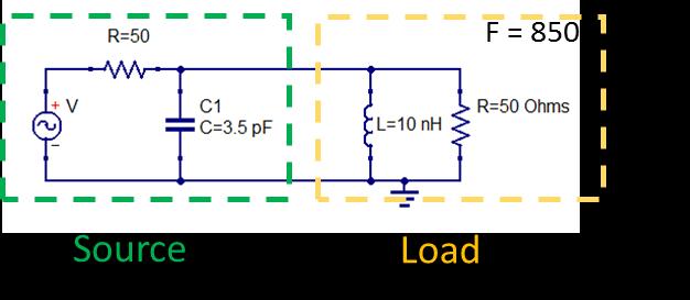
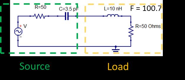
7 3. Can this stub move the impedance to the Z0 origin? 4. With a load impedance of 25 + j25 what shunt lumped element (i.e. inductor or capacitor) will bring the impedance seen by the source closest to the Z0 origin at 850 MHz? (Use whole numbers of nh or pf as appropriate). 3 Matching Networks 1. Use the following network to match 200 Ohms to a 100 Ohms source at 100 MHz 2. Use the same network to match 100 Ohms to a 50 Ohms source at 100 MHz 3. Use the following network to match 100 Ohms to 50 Ohms using the following network at 800 MHz. 4. Which network structure would you use if you were concerned about harmonic output from your product? The one shown in question 1 or question 3? 5. What inductance would you use to move an impedance of 92 + j140 to 50 Ohm line? Start by considering whether you need a shunt or series element. 7
8 4 Dual Band Antenna 1. In this exercise will use an antenna with the following reflection coefficient data. (Also available from a text file labelled antenna_a.sp1) which is in magnitude angle format. # MHZ S MA R For this exercise we will match a band from 850 to 950 for the low band and 2400 to 2500 for the high band. The raw antenna looks like this on the Smith Chart. 8
9 Remembering that series inductors and shunt capacitors move the high band more than the low band we will start by using a shunt capacitor to move the high band to the 50 Ohm circle rather than a shunt inductor. Perform the final match with a resonant circuit so that the lower band does not move, or only moves slightly, as it will be close to the center of the chart already. 9
10 5 Answer Key Introduction & Basics 1. a. Yes b. No c. Yes d. Yes e. No f. No a. 1/3 b. 0 c. 1/3 d. 1/2 e Arg 45 f db 10

11 Smith Chart 1. Complex impedances a j25 b j0 c j0 d. 20 j100 e. 15 j25 2. Gamma - Γ Arg Γ a Arg 116 b Arg 180 c Arg 0 d Arg -52 e Arg -123 See Smith Chart below for solutions. 11

12 3. No The stub does not move the impedance to the Z0 origin. A 0 length open stub leaves the Load impedance unperturbed at 25Ω and the minimum impedance is when the stub presents a short circuit resulting in a 0Ω impedance being presented to the source. The path of a stub matching element is a circle touching the load impedance and the 0. A stub can bring an impedance to the Z0 circle if it falls outside a circle that touches the real axis at 0 and Z0. (i.e. outside the shaded area to the left). 4. A shunt capacitor of value 4 pf. (25 + j25) -1 = 20 j20 ms. A positive susceptance is capacitive. 2 π 850 MHz * 4 pf = 21.4 ms recall the unit S = Ω -1 Matching Networks 1. Matching 200 Ω to 100 Ω a. First off we set Z0 as 100Ω instead of the usual 50Ω. This results in a relative impedance of 2.0 on the Smith Chart b. Using a shunt inductor the impedance will head northward in a counter-clockwise direction hitting the Z0 circle at an impedance of 1+j1 and admittance of 0.5-j.5 c. The inductor needs to have an susceptance of j0.5 - j0 (end point mines start point) at 1 GHz. Y0 (1/Z0) 1/100 = 10 ms so the inductor has a susceptance of 5 ms. L = 318 nh at 1 GHz. Using standard values we would use 300 or 330 nh. d. The impedance is now at 1 +j1 on the Smith Chart, or 100 +j100 Ω. A reactance of - j100 is now required, which requires capacitor value of 15.9 pf. Using a standard value we would use 15 pf. 12
13 2. Use the same network to match 100 Ohms to a 50 Ohms source at 100 MHz. a. The approach will be exactly the same but the shunt susceptance required will be -j10 ms instead of -j5 ms making the inductor half as large 159 nh (use 150 nh) b. Similarly the reactance for the series capacitor will now be j50 instead of j100 making the capacitor twice as large at 31.8 pf (use 33 pf). 3. Use the same approach as above, but the shunt capacitor will intersect the Z0 circle 1 j1 (0.5 +j0.5 on Admittance chart) instead of 1+ j1. (Remember we are now operating at 800 MHz). C = 2 pf L = 10 nh 4. The network in question 3 as it is a low-pass filter. 5. Moving 92 + j140 to 50 Ohm line requires following a constant conductance so the inductor is a shunt inductor. The Admittance for this point is (92 + j140) -1 = j0.005 S or j0.25 when normalized to Y0. The 0.16 conductance circle intercepts the Z0 circle at approximately 0.35 (or 7 ms). We need to move about 2 ms (7 ms 5 ms) which requires a GHz. 13
14 Dual-Band Antenna 1. The raw antenna looks like this on the Smith Chart. We may wish to move the high band northward (with a shunt inductor) or move the band southward with a shunt capacitor. We will use the capacitor since this has less impact on the low band, which is already near the center of the Smith Chart. I picked a value of capacitor that centers 2.4 and 2.45 around the 50 Ohm circle. Using ideal components and ignoring preferred values this is about 8.5 pf. ( j139 ms at GHz) We observe the following: a) A series inductor is needed to move the high band to the origin. b) A small bit of capacitance would move the low band down a touch. c) A series resonant circuit is inductive above resonance. 14
15 Thus a network like this should work for this match. Interpolating the data, a point on the 50 Ohm circle in the high band would be approximately 50 j110 at 2.42 GHz => we want a net series reactance of +j110 to reach the origin in the high band and a resonant circuit between 900 and 950 MHz (making it slightly capacitive at 850 and 900 MHz). Dual-Band Matching Network and its Performance. 15
16 Using normal value components we have several many choices. Here is an example. Dual-Band Example with Standard Value Components 16
A Walk Through the MSA Software Vector Network Analyzer Reflection Mode 12/12/09
 A Walk Through the MSA Software Vector Network Analyzer Reflection Mode 12/12/09 This document is intended to familiarize you with the basic features of the MSA and its software, operating as a Vector
DX University: Smith Charts
 DX University: Smith Charts 2010 August 9 Sponsored by the Kai Siwiak, ke4pt@amsat.org Ed Callaway, n4ii@arrl.org 2010 Aug 9 Kai, KE4PT; Ed, N4II 2 Source: http://www.sss-mag.com/pdf/smithchart.pdf 2010
Impedance Matching Techniques for Mixers and Detectors. Application Note 963
 Impedance Matching Techniques for Mixers and Detectors Application Note 963 Introduction The use of tables for designing impedance matching filters for real loads is well known [1]. Simple complex loads
Transmission Lines. Ranga Rodrigo. January 27, Antennas and Propagation: Transmission Lines 1/72
 Transmission Lines Ranga Rodrigo January 27, 2009 Antennas and Propagation: Transmission Lines 1/72 1 Standing Waves 2 Smith Chart 3 Impedance Matching Series Reactive Matching Shunt Reactive Matching
What is a matching network?
 Impedance Matching and Tuning Matching networks are used to match the impedance of one system to another Match is important for several reasons: Provides for maximum power transfer (e.g. carrying power
Amateur Extra Manual Chapter 9.4 Transmission Lines
 9.4 TRANSMISSION LINES (page 9-31) WAVELENGTH IN A FEED LINE (page 9-31) VELOCITY OF PROPAGATION (page 9-32) Speed of Wave in a Transmission Line VF = Velocity Factor = Speed of Light in a Vacuum Question
Lecture 9 - Lumped Element Matching Networks
 Lecture 9 - Lumped Element Matching Networks Microwave Active Circuit Analysis and Design Clive Poole and Izzat Darwazeh Academic Press Inc. Poole-Darwazeh 2015 Lecture 9 - Lumped Element Matching Networks
Smith Chart Calculations
 The following material was extracted from earlier editions. Figure and Equation sequence references are from the 21st edition of The ARRL Antenna Book Smith Chart Calculations The Smith Chart is a sophisticated
SINGLE & DOUBLE STUB MATCHING TECHNIQUES
 SINGLE & DOUBLE STUB MATCHING TECHNIQUES PROF.MADHURI MAHENDRA PATIL Department of Electronics and Telecommunication PRAVIN PATIL DIPLOMA COLLEGE, BHAYANDAR-401105 Abstract: The purpose of this paper is
Exercise S11= S12= S21= S22=
 Exercise 010217 The following scheme refers to an oscillator working at fosc=425 MHz. The S parameters of the transistor are also reported on the figure. ΓL L C Γs Γout OUT MATCH S11=0.69-55 S12=0.026
Fields and Waves I Spring 2005 Homework 1. Due 25 January 2005
 Due 2 January 200 1. Plane Wave Representations The numbers given in this problem are realistic but not real. That is, your answers should come out in a reasonable range, but the numbers are not based
ECE 145A and 218A. Transmission-line properties, impedance-matching exercises
 ECE 145A and 218A. Transmission-line properties, impedance-matching exercises Problem #1 This is a circuit file to study a transmission line. The 2 resistors are included to allow easy disconnection of
EC6503 Transmission Lines and WaveguidesV Semester Question Bank
 UNIT I TRANSMISSION LINE THEORY A line of cascaded T sections & Transmission lines General Solution, Physicasignificance of the equations 1. Derive the two useful forms of equations for voltage and current
EELE 3332 Electromagnetic II Chapter 11. Transmission Lines. Islamic University of Gaza Electrical Engineering Department Dr.
 EELE 3332 Electromagnetic II Chapter 11 Transmission Lines Islamic University of Gaza Electrical Engineering Department Dr. Talal Skaik 2012 1 11.6 Some Applications of Transmission Lines Transmission
Measuring Impedance With Return Loss Bridge Sam Wetterlin 11/29/08
 Measuring Impedance With Return Loss Bridge Sam Wetterlin 11/29/08 In a separate document titled Manual Return Loss Measurements, I describe how a return loss bridge (a/k/a reflection bridge) can provide
TUTORIAL #7 Using the Smith Chart
 TUTORIAL #7 Using the Smith Chart. [.9 P expanded] Use the Smith chart to find the following quantities for the transmission-line circuit in the figure below. L Z0 Z j L Z in (a) The SWR on the line. (b)
ELC 4396 RF/Microwave Circuits I Fall 2011 Final Exam December 9, 2011 Open Book/Open Notes 2 hours
 Name ELC 4396 RF/Microwave Circuits I Fall 2011 Final Exam December 9, 2011 Open Book/Open Notes 2 hours 1. The exam is open-book/open-notes. 2. A calculator may be used to assist with the test. No laptops
Impedance Calculations
 Revisiting a T-ine With Any Termination In the general case, where a transmission line is terminated in Z, the impedance along the line is given by: Z Z j z j z e e e Z Z Z( z) Z Z j z j z e e Z Z e Z
Double-Tuned Impedance Matching
 Double-Tuned Impedance Matching Alfred R. Lopez, Life Fellow, IEEE ARL Associates 4 Sarina Drive Commack, NY 11725 Tel: 631 499 2987 Fax: 631 462 0320 Cell: 631 357 9342 Email: al.lopez@ieee.org Keywords:
From the Design-Guide menu on the ADS Schematic window, select (Filters Design-Guide) > Utilities > Smith Chart Control Window.
 > Utilities > Smith Chart Control Window.") Objectives: 1. To understand the function of transmission line stubs. 2. To perform impedance matching graphically using the smith chart utility in ADS. 3. To calculate the transmission line parameters
Objectives: 1. To understand the function of transmission line stubs. 2. To perform impedance matching graphically using the smith chart utility in ADS. 3. To calculate the transmission line parameters
The Smith Chart is a sophisticated graphic tool for solving transmission line problems. One of the
 Chapter 28 Smith Chart Calculations The Smith Chart is a sophisticated graphic tool for solving transmission line problems. One of the simpler applications is to determine the feed-point impedance of an
A COMPACT DUAL-BAND POWER DIVIDER USING PLANAR ARTIFICIAL TRANSMISSION LINES FOR GSM/DCS APPLICATIONS
 Progress In Electromagnetics Research Letters, Vol. 1, 185 191, 29 A COMPACT DUAL-BAND POWER DIVIDER USING PLANAR ARTIFICIAL TRANSMISSION LINES FOR GSM/DCS APPLICATIONS T. Yang, C. Liu, L. Yan, and K.
REFLECTIONS AND STANDING WAVE RATIO
 Page 1 of 9 THE SMITH CHART.In the last section we looked at the properties of two particular lengths of resonant transmission lines: half and quarter wavelength lines. It is possible to compute the impedance
Chapter 4 Impedance Matching
 Chapter 4 Impedance Matching Quarter-wave transformer, series section transformer Stub matching, lumped element networks, feed point location 3 Gamma match 4 Delta- and T-match, Baluns -port network Smith
ECEN 5014, Spring 2009 Special Topics: Active Microwave Circuits Zoya Popovic, University of Colorado, Boulder
 ECEN 5014, Spring 2009 Special Topics: Active Microwave Circuits Zoya opovic, University of Colorado, Boulder LECTURE 3 MICROWAVE AMLIFIERS: INTRODUCTION L3.1. TRANSISTORS AS BILATERAL MULTIORTS Transistor
JEREMY HALEY, WG9T LONGMONT AMATEUR RADIO CLUB. Longmont Amateur Radio Club
 RF IMPEDANCE AND THE SMITH CHART JEREMY HALEY, WG9T LONGMONT AMATEUR RADIO CLUB 1 RESISTANCE, REACTANCE, AND IMPEDANCE RESISTANCE Energy conversion to heat. REACTANCE Capacitance: Energy storage in electric
Bandpass Filters Using Capacitively Coupled Series Resonators
 8.8 Filters Using Coupled Resonators 441 B 1 B B 3 B N + 1 1 3 N (a) jb 1 1 jb jb 3 jb N jb N + 1 N (b) 1 jb 1 1 jb N + 1 jb N + 1 N + 1 (c) J 1 J J Z N + 1 0 Z +90 0 Z +90 0 Z +90 0 (d) FIGURE 8.50 Development
IEEE CX4 Quantitative Analysis of Return-Loss
 IEEE CX4 Quantitative Analysis of Return-Loss Aaron Buchwald & Howard Baumer Mar 003 Return Loss Issues for IEEE 0G-Base-CX4 Realizable Is the spec realizable with standard packages and I/O structures
The Amazing MFJ 269 Author Jack Tiley AD7FO
 The Amazing MFJ 269 Author Jack Tiley AD7FO ARRL Certified Emcomm and license class Instructor, Volunteer Examiner, EWA Technical Coordinator and President of the Inland Empire VHF Club What Can be Measured?
ECEN 4634/5634, MICROWAVE AND RF LABORATORY
 ECEN 4634/5634, MICROWAVE AND RF LABORATORY Final Exam December 18, 2017 7:30-10:00pm 150 minutes, closed book, 1 sheet allowed, no calculators (estimates need to be within 3dB) Part 1 (60%). Briefly answer
Application Note Receivers MLX71120/21 With LNA1-SAW-LNA2 configuration
 Designing with MLX71120 and MLX71121 receivers using a SAW filter between LNA1 and LNA2 Scope Many receiver applications, especially those for automotive keyless entry systems require good sensitivity
Resonant and Nonresonant Lines. Input Impedance of a Line as a Function of Electrical Length
 Exercise 3-3 The Smith Chart, Resonant Lines, EXERCISE OBJECTIVES Upon completion of this exercise, you will know how the input impedance of a mismatched line varies as a function of the electrical length
A NOVEL DUAL-BAND BANDPASS FILTER USING GENERALIZED TRISECTION STEPPED IMPEDANCE RESONATOR WITH IMPROVED OUT-OF-BAND PER- FORMANCE
 Progress In Electromagnetics Research Letters, Vol. 21, 31 40, 2011 A NOVEL DUAL-BAND BANDPASS FILTER USING GENERALIZED TRISECTION STEPPED IMPEDANCE RESONATOR WITH IMPROVED OUT-OF-BAND PER- FORMANCE X.
Exercise 1: Series Resonant Circuits
 Series Resonance AC 2 Fundamentals Exercise 1: Series Resonant Circuits EXERCISE OBJECTIVE When you have completed this exercise, you will be able to compute the resonant frequency, total current, and
A MINIATURIZED OPEN-LOOP RESONATOR FILTER CONSTRUCTED WITH FLOATING PLATE OVERLAYS
 Progress In Electromagnetics Research C, Vol. 14, 131 145, 21 A MINIATURIZED OPEN-LOOP RESONATOR FILTER CONSTRUCTED WITH FLOATING PLATE OVERLAYS C.-Y. Hsiao Institute of Electronics Engineering National
University of Jordan School of Engineering Electrical Engineering Department. EE 219 Electrical Circuits Lab
 University of Jordan School of Engineering Electrical Engineering Department EE 219 Electrical Circuits Lab EXPERIMENT 7 RESONANCE Prepared by: Dr. Mohammed Hawa EXPERIMENT 7 RESONANCE OBJECTIVE This experiment
Lecture 4. Maximum Transfer of Power. The Purpose of Matching. Lecture 4 RF Amplifier Design. Johan Wernehag Electrical and Information Technology
 Johan Wernehag, EIT Lecture 4 RF Amplifier Design Johan Wernehag Electrical and Information Technology Design of Matching Networks Various Purposes of Matching Voltage-, Current- and Power Matching Design
Application Note No. 022
 Application Note, Rev. 2.0, Jan. 2007 Application Note No. 022 Simple Microstrip Matching for all Impedances RF & Protection Devices Edition 2007-01-17 Published by Infineon Technologies AG 81726 München,
Antenna Matching Within an Enclosure Part II: Practical Techniques and Guidelines
 Antenna Matching Within an Enclosure Part II: Practical Techniques and Guidelines By Johnny Lienau, RF Engineer June 2012 Antenna selection and placement can be a difficult task, and the challenges of
Homework Assignment 05
 Homework Assignment 05 Question (2 points each unless otherwise indicated)(20 points). Estimate the parallel parasitic capacitance of a mh inductor with an SRF of 220 khz. Answer: (2π)(220 0 3 ) = ( 0
A Walk Through the MSA Software Vector Network Analyzer Transmission Mode 12/18/09
 A Walk Through the MSA Software Vector Network Analyzer Transmission Mode 12/18/09 This document is intended to familiarize you with the basic features of the MSA and its software, operating as a Vector
Case Study: Osc1 Design of a Reflection Oscillator
 MICROWAVE AND RF DESIGN Case Study: Osc1 Design of a Reflection Oscillator Presented by Michael Steer Reading: Chapter 20, Section 20.4 Index: CS_Osc1 Based on material in Microwave and RF Design: A Systems
Experiment #51 -- Filter Design #2
 Experiment #51 -- Filter Design #2 Ed Wetherhold W3NQN caught your editor crossing his terms: "Return coefficient" is incorrect. What was meant is, of course, "reflection coefficient". Return loss is another
 VALLIAMMAI ENGINEERING COLLEGE SRM Nagar, Kattankulathur-603 203 DEPARTMENT OF ELECTRONICS AND COMMUNICATION ENGINEERING EC6503 TRANSMISSION LINES AND WAVEGUIDES YEAR / SEMESTER: III / V ACADEMIC YEAR:
AM036MX-QG-R 1 WATT, 2 GHz POWER AMPLIFIER
 AM036MX-QG-R 1 WATT, 2 GHz POWER AMPLIFIER AN136 January 2011 REV 3 INTRODUCTION This application note describes the design of a one-watt, single stage power amplifier at 2GHz using AMCOM s low cost surface
AN643. Si446x/Si4362 RX LNA Matching. 1. Introduction. 2. Match Network Topology Three-Element Match Network
 Si446x/Si4362 RX LNA Matching 1. Introduction The purpose of this application note is to provide a description of the impedance matching of the RX differential low noise amplifier (LNA) on the Si446x/Si4362
his report is my recent analysis of the EH antenna using the Pspice program and considering the antenna as a set of circuit elements.
 his report is my recent analysis of the EH antenna using the Pspice program and considering the antenna as a set of circuit elements. The antenna can be considered as a set of circuit elements because
A Coupled-Fed Reconfigurable Antenna for Internal LTE Mobile Phone Applications
 Progress In Electromagnetics Research Letters, Vol. 7, 39 44, 217 A Coupled-Fed Reconfigurable Antenna for Internal LTE Mobile Phone Applications Xinxing Zhong * Abstract In this paper, a multi-frequency
Γ L = Γ S =
 TOPIC: Microwave Circuits Q.1 Determine the S parameters of two port network consisting of a series resistance R terminated at its input and output ports by the characteristic impedance Zo. Q.2 Input matching
Case Study: Osc2 Design of a C-Band VCO
 MICROWAVE AND RF DESIGN Case Study: Osc2 Design of a C-Band VCO Presented by Michael Steer Reading: Chapter 20, 20.5,6 Index: CS_Osc2 Based on material in Microwave and RF Design: A Systems Approach, 2
Project. A circuit simulation project to transition you from lumped component-based circuit theory In Part 1 and Part 2, you built an LC network:
 Project A circuit simulation project to transition you from lumped component-based circuit theory In Part 1 and Part 2, you built an LC network: And, you did transient simulations of the following circuits
Transmission Lines As Impedance Transformers
 Transmission Lines As Impedance Transformers Bill Leonard N0CU 285 TechConnect Radio Club 2017 TechFest Topics Review impedance basics Review Smith chart basics Demonstrate how antenna analyzers display
Lecture 7: Transmission Line Matching Using Lumped L Networks.
 Whites, EE 48/58 ecture 7 Page of ecture 7: Transmission ine Matching Using umped Networks. Impedance matching (or simply matching ) one portion of a circuit to another is an immensely important part of
14 Sept 2006 Page 1 of 11 TRF7960 RFID Reader & Antenna Circuits. 1.) Introduction
 Introduction") 14 Sept 2006 Page 1 of 11 TRF7960 RFID Reader & Antenna Circuits 1.) Introduction This paper describes the design method for determining an antenna matching circuit together with Tx and Rx interface circuits
14 Sept 2006 Page 1 of 11 TRF7960 RFID Reader & Antenna Circuits 1.) Introduction This paper describes the design method for determining an antenna matching circuit together with Tx and Rx interface circuits
Application Note 5499
 MGA-31389 and MGA-31489 High-Gain Driver Amplifier Using Avago MGA-31389 and MGA-31489 Application Note 5499 Introduction The MGA-31389 and MGA-31489 from Avago Technologies are.1 Watt flat-gain driver
Lecture 4 RF Amplifier Design. Johan Wernehag, EIT. Johan Wernehag Electrical and Information Technology
 Lecture 4 RF Amplifier Design Johan Wernehag, EIT Johan Wernehag Electrical and Information Technology Lecture 4 Design of Matching Networks Various Purposes of Matching Voltage-, Current- and Power Matching
Chapter 30 Inductance, Electromagnetic. Copyright 2009 Pearson Education, Inc.
 Chapter 30 Inductance, Electromagnetic Oscillations, and AC Circuits 30-7 AC Circuits with AC Source Resistors, capacitors, and inductors have different phase relationships between current and voltage
Exercise 1: Series RLC Circuits
 RLC Circuits AC 2 Fundamentals Exercise 1: Series RLC Circuits EXERCISE OBJECTIVE When you have completed this exercise, you will be able to analyze series RLC circuits by using calculations and measurements.
TEST EQUIPMENT PLUS. Signal Hound USB-SA44B / USB-TG44A. Application Note 1: The Smith Chart. Rev. 0
 Rev. 0 TEST EQUIPMENT PLUS Signal Hound USB-SA44B / USB-TG44A Application Note 1: The Smith Chart USING THE SMITH CHART Chapter 1 1 Using the Smith Chart Making Single-Frequency Vector Impedance Measurements
RF Devices and RF Circuit Design for Digital Communication
 RF Devices and RF Circuit Design for Digital Communication Agenda Fundamentals of RF Circuits Transmission ine Reflection Coefficient & Smith Chart Impedance Matching S-matrix Representation Amplifiers
EE 340 Transmission Lines. Spring 2012
 EE 340 Transmission Lines Spring 2012 Physical Characteristics Overhead lines An overhead transmission line usually consists of three conductors or bundles of conductors containing the three phases of
Range Considerations for RF Networks
 TI Technology Days 2010 Range Considerations for RF Networks Richard Wallace Abstract The antenna can be one of the most daunting components of wireless designs. Most information available relates to large
Equivalent Circuit Determination of Quartz Crystals
 Page 1 of 11 Equivalent Circuit Determination of Quartz Crystals By Stephan Synkule & Florian Hämmerle 2010 Omicron Lab V1.1 Visit www.omicron-lab.com for more information. Contact support@omicron-lab.com
RF Devices and RF Circuit Design for Digital Communication
 RF Devices and RF Circuit Design for Digital Communication Agenda Fundamentals of RF Circuits Transmission ine Reflection Coefficient & Smith Chart Impedance Matching S-matrix Representation Amplifiers
Amateur Radio (G3TXQ) - Folded dipoles
 - Folded dipoles") A. Introduction Amateur Radio (G3TXQ) - Folded dipoles A recent interest in "bent" half-wave dipoles led me to look into the theory of the classic Folded Dipole (FD) in some depth. Dipoles bent into a
A. Introduction Amateur Radio (G3TXQ) - Folded dipoles A recent interest in "bent" half-wave dipoles led me to look into the theory of the classic Folded Dipole (FD) in some depth. Dipoles bent into a
Transmission Lines. Ranga Rodrigo. January 13, Antennas and Propagation: Transmission Lines 1/46
 Transmission Lines Ranga Rodrigo January 13, 2009 Antennas and Propagation: Transmission Lines 1/46 1 Basic Transmission Line Properties 2 Standing Waves Antennas and Propagation: Transmission Lines Outline
An Oscillator Scheme for Quartz Crystal Characterization.
 An Oscillator Scheme for Quartz Crystal Characterization. Wes Hayward, 15Nov07 The familiar quartz crystal is modeled with the circuit shown below containing a series inductor, capacitor, and equivalent
The Design of 2.4GHz Bipolar Oscillator by Using the Method of Negative Resistance Cheng Sin Hang Tony Sept. 14, 2001
 The Design of 2.4GHz Bipolar Oscillator by Using the Method of Negative Resistance Cheng Sin Hang Tony Sept. 14, 2001 Introduction In this application note, the design on a 2.4GHz bipolar oscillator by
Using the LC-Lumped Element Model for Transmission Line Experiments
 Session 2526 Using the LC-Lumped Element Model for Transmission Line Experiments F. Jalali Electronic Engineering Technology Department Fort Valley State University Introduction An array of cascaded lumped-element
Oversimplification of EMC filter selection
 Shortcomings of Simple EMC Filters Antoni Jan Nalborczyk MPE Ltd. Liverpool, United Kingdom Oversimplification of EMC filter selection to reduce size and cost can often be a false economy as anticipated
VELAMMAL ENGINEERING COLLEGE, CHENNAI-66 DEPARTMENT OF ELECTRONICS AND COMMUNICATION ENGINEERING
 VELAMMAL ENGINEERING COLLEGE, CHENNAI-66 DEPARTMENT OF ELECTRONICS AND COMMUNICATION ENGINEERING TUTORIAL SHEET- 1, 2, 3, 4 & 5 UNIT 1 TRANSMISSION LINE THEORY 1. A transmission line has a characteristic
800 MHz Test Fixture Design
 Application Note Rev. 0, 7/993 NOTE: The theory in this application note is still applicable, but some of the products referenced may be discontinued. 800 MHz Test Fixture Design By: Dan Moline Although
EC Transmission Lines And Waveguides
 EC6503 - Transmission Lines And Waveguides UNIT I - TRANSMISSION LINE THEORY A line of cascaded T sections & Transmission lines - General Solution, Physical Significance of the Equations 1. Define Characteristic
Chapter 2 Displaying Characteristics
 Chapter 2 Displaying Characteristics Impedance Characteristics of Chip Beads Chip beads are parts used to prevent EMI and control decoupling of LSI power source lines and to control over/under shooting
Technical Manual For Chips Multilayer Antenna Matching Adjustment Method LDA31 series
 Technical Manual For Chips Multilayer Antenna Matching Adjustment Method LDA31 series Application: 2.4GHz Wireless Bluetooth TM 1/17 Chip Antenna is a special component to change characteristics and this
Impedance Transformation with Transmission Lines
 Impedance Transformation with Transmission Lines Software Installation and Operation Manual Don Cochran WAØJOW 21826 Gardner Rd. Spring Hill, KS 66083 (913) 856-4075 Manual Revision 1 Page 1 Table of Contents
Simulation of GaAs phemt Ultra-Wideband Low Noise Amplifier using Cascaded, Balanced and Feedback Amplifier Techniques
 2011 International Conference on Circuits, System and Simulation IPCSIT vol.7 (2011) (2011) IACSIT Press, Singapore Simulation of GaAs phemt Ultra-Wideband Low Noise Amplifier using Cascaded, Balanced
Aries Kapton CSP socket
 Aries Kapton CSP socket Measurement and Model Results prepared by Gert Hohenwarter 5/19/04 1 Table of Contents Table of Contents... 2 OBJECTIVE... 3 METHODOLOGY... 3 Test procedures... 4 Setup... 4 MEASUREMENTS...
Master Thesis. Mobile Phone Antenna Modelling. Umut Bulus. Supervised by Prof. Dr.-Ing. K. Solbach
 Master Thesis Mobile Phone Antenna Modelling Umut Bulus Supervised by Prof. Dr.-Ing. K. Solbach 2.3.28 Contents Introduction Theoretical Background Antenna Measurements on Different PCB Variations Investigation
BANDPASS CAVITY RESONATORS
 BANDPASS CAVITY RESONATORS S Parameters Measurements and Modelling Using Bandpass Cavities for Impedance Matching Jacques Audet VE2AZX Web: ve2azx.net With the collaboration of Luc Laplante VE2ULU May
EC TRANSMISSION LINES AND WAVEGUIDES TRANSMISSION LINES AND WAVEGUIDES
 TRANSMISSION LINES AND WAVEGUIDES UNIT I - TRANSMISSION LINE THEORY 1. Define Characteristic Impedance [M/J 2006, N/D 2006] Characteristic impedance is defined as the impedance of a transmission line measured
International Journal of Advance Engineering and Research Development DESIGN OF DUPLEXER USING MICROSTRIP FILTERS FOR LOW POWER GSM APPLICATIONS
 Scientific Journal of Impact Factor(SJIF): 3.134 International Journal of Advance Engineering and Research Development Volume 2,Issue 4, April -2015 e-issn(o): 2348-4470 p-issn(p): 2348-6406 DESIGN OF
Fields and Waves I Spring 2008 Homework 1
 Fields and Waves I Spring 28 Due 23 January 28 at : pm Some of the solution is found in the text below, some is attached at the end. 1. Waves and Phasor Notation Be sure that you read the following questions
Adjust Antenna Tuners Antenna Measurements Capacitor Measurement Measure Feed Point Impedance Measure Ground Loss Inductor Measurement
 The Micro908 antenna analyzer is an extremely useful instrument to have around the ham shack or homebrewer s workbench. This section describes the basic uses, as well as some advanced techniques for which
MFJ269 Antenna Analyzer Theory And Use
 MFJ69 Antenna Analyzer Theory And Use By Jim McVey, ACEU www.mcveyelectronics.com The MFJ 69 is a handy instrument for checking your antenna, test coax, or to even test tuners. Although it has it s limitations
Uncertainties of immunity measurements
 Uncertainties of immunity measurements DTI-NMSPU project R2.2b1 Annex A Description of the circuit model (conducted immunity) Annex A Description of the circuit model (conducted immunity) Annex A Description
EE 340 Transmission Lines
 EE 340 Transmission Lines Physical Characteristics Overhead lines An overhead transmission line usually consists of three conductors or bundles of conductors containing the three phases of the power system.
Introduction to RF Measurement and Nonideal Components The Vector Network Analyzer UCSB - ECE145A/ECE218A Winter 2007
 Goals: Introduction to RF Measurement and Nonideal Components The Vector Network Analyzer UCSB - ECE145A/ECE218A Winter 2007 (a) Introduction to the vector network analyzer and measurement of S-parameters.
Exploratory Paper. Vector Network Analyzer Calibration Pitfalls. A Work in Progress. Teltest Electronics Laboratories, Inc.
 Teltest Electronics Laboratories, Inc. Austin, Texas Exploratory Paper Vector Network Analyzer Calibration Pitfalls Rev 0.03 Jim Satterwhite K4HJU A Work in Progress Teltest Electronics 5/3/2010 5/4/2010
University of KwaZulu-Natal
 University of KwaZulu-Natal School of Engineering Electrical, Electronic & Computer Engineering UNIVERSITY EXAMINATIONS NOVEMBER 2015 ENEL3EM: EM THEORY Time allowed: 2 hours Instructions to Candidates:
PARAMETER CONDITIONS TYPICAL PERFORMANCE Operating Supply Voltage 3.1V to 3.5V Supply Current V CC = 3.3V, LO applied 152mA
 DESCRIPTION LT5578 Demonstration circuit 1545A-x is a high linearity upconverting mixer featuring the LT5578. The LT 5578 is a high performance upconverting mixer IC optimized for output frequencies in
VALLIAMMAI ENGINEERING COLLEGE
 VALLIAMMAI ENGINEERING COLLEGE SRM Nagar, Kattankulathur 603 203 DEPARTMENT OF ELECTRONICS AND COMMUNICATION ENGINEERING QUESTION BANK V SEMESTER EC6503 TRANSMISSION LINES AND WAVEGUIDES Regulation 2013
APPLICATION SPECIFICATION
 2.4/5GHZ SMT CHIP ANTENNA 1.0 SCOPE This specification describes the antenna application and recommended PCB layout for the Molex 2.4/5 GHz SMT Chip Antenna. The information in this document is for reference
Metamaterial Inspired CPW Fed Compact Low-Pass Filter
 Progress In Electromagnetics Research C, Vol. 57, 173 180, 2015 Metamaterial Inspired CPW Fed Compact Low-Pass Filter BasilJ.Paul 1, *, Shanta Mridula 1,BinuPaul 1, and Pezholil Mohanan 2 Abstract A metamaterial
EXPERIMENT EM3 INTRODUCTION TO THE NETWORK ANALYZER
 ECE 351 ELECTROMAGNETICS EXPERIMENT EM3 INTRODUCTION TO THE NETWORK ANALYZER OBJECTIVE: The objective to this experiment is to introduce the student to some of the capabilities of a vector network analyzer.
Lowpass and Bandpass Filters
 Microstrip Filters for RF/Microwave Applications. Jia-Sheng Hong, M. J. Lancaster Copyright 2001 John Wiley & Sons, Inc. ISBNs: 0-471-38877-7 (Hardback); 0-471-22161-9 (Electronic) CHAPTER 5 Lowpass and
Transmission Lines. Chapter 24. Basic Theory of Transmission Lines
 Chapter 24 Transmission Lines Basic Theory of Transmission Lines The desirability of installing an antenna in a clear space, not too near buildings or power and telephone lines, cannot be stressed too
The Coaxial Trap Confusion (mostly resolved?)
") The Coaxial Trap Confusion (mostly resolved?) Background Antenna traps need an inductor and a capacitor in a parallel circuit to effectively cut off the end of the antenna for some higher frequency giving
The Coaxial Trap Confusion (mostly resolved?) Background Antenna traps need an inductor and a capacitor in a parallel circuit to effectively cut off the end of the antenna for some higher frequency giving
Loop and Slot Antennas
 Loop and Slot Antennas Prof. Girish Kumar Electrical Engineering Department, IIT Bombay gkumar@ee.iitb.ac.in (022) 2576 7436 Loop Antenna Loop antennas can have circular, rectangular, triangular or any
"High Frequency Ceramic Solutions"
 2.45 GHz Antenna ( Orientation P/N 2450AT45A100 Detail Specification: 07/10/09 Page 1 of 9 General Specifications Part Number 2450AT45A100 Input Power 3W max. Frequency Range 2400-2500 Mhz Impedance 50