FEB 18 Rev D
|
|
|
- Calvin Robertson
- 6 years ago
- Views:
Transcription
1 ORIGINAL INSTRUCTIONS Terminal and Splice Crimping Die Assemblies Instruction Sheet FEB 18 Rev D PROPER USE GUIDELINES Cumulative trauma disorders can result from the prolonged use of manually powered hand tools. Hand tools are intended for occasional use and low volume applications. A wide selection of powered application equipment for extended-use, production operations is available. Crimping Die Assemblies Hand Tool Instruction Sheet Figure 1 1. INTRODUCTION The die assemblies listed in Figure 1 will crimp terminals and splices in multiple product families. With wire sizes 26 through 10 AWG: PIDG* terminals and splices PIDG insulation restricting nylon terminals PIDG PTFE STRATO-THERM* terminals With wire sizes 22 through 10 AWG: PLASTI-GRIP* terminals DIAMOND GRIP* terminals and splices Reasons for reissue of this instruction sheet are provided in Section 7, REVISION SUMMARY. Dimensions in this instruction sheet are in millimeters [with inches in brackets]. Illustrations and figures are for reference only and are not drawn to scale TE Connectivity family of companies All Rights Reserved *Trademark PRODUCT INFORMATION This controlled document is subject to change. For latest revision and Regional Customer Service, visit our website at TE Connectivity, TE connectivity (logo), and TE (logo) are trademarks. Other logos, product, and/or company names may be trademarks of their respective owners. 1 of 12
2 2. DESCRIPTION The die assembly consists of a moving die and a stationary die (see Figure 1). The dies and the terminals and splices are color-coded according to wire size for easy identification. When the terminal and splice are properly crimped in the correct die assembly, 1 dot or 2 dots (depending on wire size) will appear embossed on the top and bottom of the terminal or splice. DIAMOND GRIP terminals and splices do not have a color code or crimp dot code. 3. CRIMPING PRODECURE The dies are coated with oil to prevent rust and corrosion. Wipe this oil from the dies, particularly from the crimping area. 1. Install the die assembly according to the instructions included with the tool. Refer to Section 4 for insulation crimp adjustment. 2. Strip the wire to the dimensions provided in Figure 2, 3, 4, or 5, depending on the wire size and product to be crimped. Crimp Wire Strip Length Die Wire Size Range Color Dot Terminal Splice Assembly (AWG) Code Code Min Max Min Max Yellow [.156] 4.78 [.188] 4.37 [.172] 5.16 [.203] White [.188] 5.56 [.219] 5.56 [.219] 6.35 [.250] Red or HD Blue [.203] 5.94 [.234] 6.35 [.250] 7.14 [.281] Yellow [.344] 9.52 [.375] 7.95 [.313] 8.74 [.344] Lg Exp or HD Yellow Use only in Tool Figure 2 Rev D 2 of 12
3 Wire Crimp Terminal Die Color Dot Assembly Size Insulation Diameter Insulation Code (AWG) Range Code Color Stripe [ ] Black Yellow [ ] Blue [ ] Green [ ] Red 1 Red [ ] White [ ] Blue Blue [ ] Green [ ] Yellow Yellow [ ] Brown Use only in Tool Figure 3 Wire Strip Length Min Max 4.78 [.188] 5.56 [.219] 6.35 [.250] 7.14 [.281] 6.35 [.250] 7.14 [.281] 9.52 [.375] [.406] PIDG PTFE STRATO-THERM Terminals Die Assembly Wire Size Range Wire Strip Length Color Code Crimp Dot Code (AWG) Min Max Black Green [.156] 4.78 [.188] Orange White [.203] 5.94 [.234] Black [.313] 8.74 [.344] Use only in Tool Figure 4 Wire Strip Length Wire Size Range Die Assembly Terminal Splice (AWG) Min Max Min Max [.172] 5.16 [.203] 5.16 [.203] 5.94 [.234] Figure 5 Rev D 3 of 12
![3. Place the terminal or splice in the stationary die as shown in Figure 6, 7, or 8. Dies will not accommodate terminals having a tongue width exceeding 11.91 [.469].](/docs-images/75/72828676/images/4-2.jpg "PIDG Terminal, PIDG PTFE STRATO- THERM Terminal, PLASTI-GRIP Terminal, and DIAMOND GRIP Terminal To Locate PIDG PTFE STRATO-THERM Terminal, Pull Locator Down Slightly Figure 6 Figure 7 Figure 8 4.")

4 3. Place the terminal or splice in the stationary die as shown in Figure 6, 7, or 8. Dies will not accommodate terminals having a tongue width exceeding [.469]. PIDG Terminal, PIDG PTFE STRATO- THERM Terminal, PLASTI-GRIP Terminal, and DIAMOND GRIP Terminal To Locate PIDG PTFE STRATO-THERM Terminal, Pull Locator Down Slightly Figure 6 Figure 7 Figure 8 4. Close the tool handles until the terminal or splice is held firmly in place. 5. Insert the stripped wire into the insulation barrel, as follows: Terminal: until the wire butts against the locator Splice: until the wire butts against the wire stop in the splice 6. Complete the crimp by closing the tool handles until the ratchet releases. 7. Allow the handles to open fully and remove the crimped connector. If crimping a splice, proceed as follows: a. Position the uncrimped insulation barrel in the stationary die (Note: If the splice cannot be turned, rotate the tool). b. Close the handles until the splice is held firmly in place, insert the stripped wire, and complete the crimp. CAUTION Damaged product should not be used. If a damaged connector is evident, it should be cut from the wire and replaced with a new one. DO NOT re-terminate terminals or splices. Rev D 4 of 12
5 4. INSULATION CRIMP ADJUSTMENT 4.1. PIDG Terminals and Splices, PIDG PTFE STRATO-THERM Terminals, and DIAMOND GRIP Terminals and Splices The insulation barrel crimping section of the moving die has three crimp positions: No. 1 (tight), No. 2 (medium), and No. 3 (loose). Adjust the insulation crimp as follows: PIDG terminals and splices and DIAMOND GRIP terminals and splices feature an insulation grip. 1. Turn both insulation crimp adjustment spacers so they fit into the notch in the side of the die (see Figure 1). This is the loose (Position No. 3) crimp setting. The moving die must be removed from the die holder to make this adjustment. 2. Insert the moving die into the die holder. Turn the die holding screw enough to hold the die firmly in place. DO NOT tighten the die holding screw at this time. 3. Insert an UNSTRIPPED wire into ONLY the insulation barrel of the terminal or splice. 4. Make a test crimp. Close the moving die on the terminal or splice and hold the moving die in the bottomed position. Tighten the die holding screw while the dies are bottomed, then complete the crimping cycle. 5. Remove the terminal or splice from the dies, and check the insulation grip by bending the wire back and forth ONCE. The terminal sleeve should retain the grip on the wire insulation. If the wire pulls out, set the insulation crimp adjustment to the next tighter position as follows: a. Remove the moving die from the die holder. b. Turn the lower insulation adjustment spacer 90 degrees so it fits between the moving die and the die holder. Note: No. 2 will appear on the corner of the spacer. c. Repeat the test crimp and adjust the moving die as necessary until the desired insulation grip is obtained. 6. With both adjustment spacers placed between the moving die and the die holder, the die is set in the tightest insulation crimping position. Note: No. 1 will appear on the corner of the top spacer PLASTI-GRIP Terminal The insulation crimping section of the moving die has three crimp positions: No. 1 (tight), No. 2 (medium), and No. 3 (loose). Adjust the insulation crimp as follows: PLASTI-GRIP terminals feature a wire insulation support only. 1. Use Position No. 3 for wire having a large insulation diameter. Remove the moving die from the die holder. Turn both insulation adjustment spacers so that they fit into the notch in the side of the die (see Figure 1). 2. Use Position No. 2 for wire having a medium insulation diameter. Remove the moving die from the die holder. Turn the lower insulation adjustment spacer 90 degrees so that it fits between the moving die and the die holder. Note: No. 2 will appear on the corner of the spacer nearest the color code dot. 3. Use Position No. 1 for wire having a small insulation diameter. Turn both insulation adjustment spacers so they will fit between the moving die and the die holder. Note: No. 1 will appear on the corner of the top spacer nearest the color dot code. Rev D 5 of 12
6 5. MAINTENANCE AND INSPECTION A maintenance and inspection program should be performed periodically. It is recommended that initial frequency of inspection be performed once a month. The frequency of an inspection is dependent upon: The care, amount of use, and handling of the dies, Type and size of the products applied, Degree of operator skill, Presence of abnormal amounts of dust and dirt, and Your own established standards. Each die assembly is inspected before shipment. It is recommended that the die assembly be inspected immediately upon arrival at your facility to ensure that it conforms to the dimensions provided in the customer drawings and that it has not been damaged during shipment Cleaning Do not allow deposits of dirt, grease, and foreign matter to accumulate in the die closure area and on the bottoming surfaces of the dies. These deposits may prevent the dies from bottoming fully and may also cause excessive wear in the die closure surfaces, thereby affecting the quality of the crimp. Clean the dies frequently with a soft cloth Visual Inspection Visually inspect the die closure surfaces for broken, chipped, or pitted conditions. Although dies may gage within permissible limits, worn or damaged die closure surfaces are objectionable and can affect the quality of the crimp. Examples of possible damaged die surfaces are shown in Figure 9. Figure Gaging the Crimping Chamber This inspection requires the use of plug gages conforming to the dimensions provided in Figure 10. To gage the crimping chamber, proceed as follows: 1. Remove traces of oil or dirt from the crimping chamber and plug gage members. 2. Turn both insulation crimp adjustment spacers so they fit into the notch in the side of the die (see Figure 1). This is the loose (Position No. 3) crimp setting. This will provide access to the wire barrel section of the crimping chamber for plug gaging. 3. Insert both dies in the tool die holders. 4. For the hand tool, close the handles of the tool until the dies bottom. DO NOT apply additional pressure to the tool handles. Actuate the tool until the dies bottom. CAUTION If using a pneumatic tool, reduce the air supply pressure to a range between 15 and 20 psi [103.4 and kpa] before actuating the tool. Rev D 6 of 12


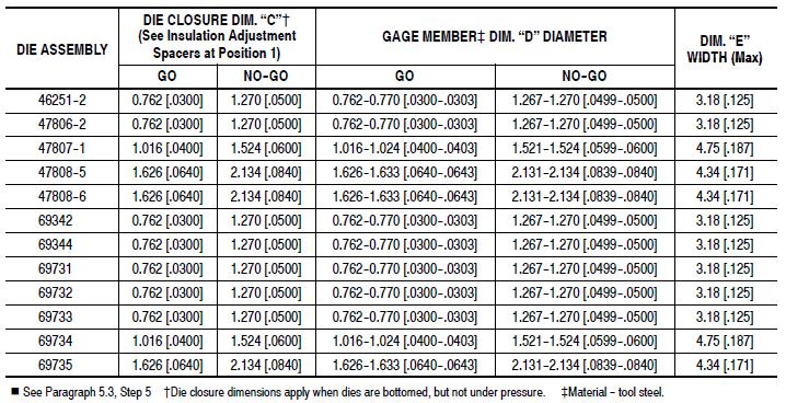
7 Figure 10 Rev D 7 of 12
 for gaging. 6.")
8 5. If the position of the locator and the insulation barrel section of the crimping chamber prevent gaging the wire barrel section of the crimping chamber, remove the die assembly from the hand tool, and rotate the locator 180 degrees. This will allow access to the wire barrel section. The die assembly can then be placed in a vise (using light pressure) for gaging. 6. With the wire barrel crimping section of the dies bottomed, check the wire barrel section using the proper plug gage. Hold the gage in a straight alignment with the crimping chamber and carefully insert (without forcing) the GO member, and then the NO-GO member (reference Figure 11 Wire Barrel). The GO member must pass completely through the crimping chamber. The NO-GO member may enter partially, but must not pass completely through the wire barrel section of the crimping chamber. Figure Remove the moving die from the tool die holder. 8. Reposition the insulation adjustment spacers to the No. 1 position (reference Section 4 for insulation crimp position adjustment procedures). 9. Insert the moving die into the tool die holder. 10. With the wire barrel crimping section of the dies bottomed, check the insulation barrel section of the crimping chamber using the proper plug gage in the same manner as step 6 (reference Figure 11 Insulation Barrel). If the crimping chamber conforms to the gage inspection, the dies may be considered dimensionally correct and should be lubricated with a THIN coat of any good SAE 20 motor oil. If the crimping chamber DOES NOT conform to the gage inspection, the dies must be returned for further evaluation and repair. Rev D 8 of 12
9 6. REPLACEMENT AND REPAIR Customer-replaceable parts are listed in Figure 12. A complete inventory should be stocked and controlled to prevent lost time when replacement of parts is necessary. Parts other than those listed should be replaced by TE Connectivity to ensure quality and reliability. Order replacement parts through your TE representative, or call , or send a facsimile of your purchase order to , or write to: CUSTOMER SERVICE ( ) TE CONNECTIVITY CORPORATION PO BOX 3608 HARRISBURG PA For customer repair service, call Figure 12a Rev D 9 of 12
10 Figure 12b Rev D 10 of 12
11 Figure 12c Rev D 11 of 12
. Corrected Figure references in paragraph 5.3.6. and 5.3.10.")
12 Figure 12d 7. REVISION SUMMARY Changed terminal name from PIDG STRATO-THERM to PIDG PTFE STRATO-THERM (5 places). Updated format, logo and enterprise name Moved some figures due to formatting changes (only Figure 12 was renumbered). Corrected Figure references in paragraph and Corrected Section reference in paragraph 3; 2 nd and paragraph Rev D 12 of 12
APR 15 Rev A
 ORIGINAL INSTRUCTIONS CERTI-CRIMP* Hand Tools 47386-4, 47387-7, and 525690-1 Instruction Sheet 411-1050 24 APR 15 Rev A PROPER USE GUIDELINES Cumulative Trauma Disorders can result from the prolonged use
Terminal and Splice , , and JUN 12 Rev D NOTE. CERTI-CRIMP* Hand Crimping Tool Ratchet Control CAUTION NOTE
 Terminal and Splice Instruction Sheet Crimping Tools 408-1254 69339, 69354-1, and 69355 11 JUN 12 PROPER USE GUIDELINES Cumulative Trauma Disorders can result from the prolonged use of manually powered
SOLISTRAND* Crimping Dies
 SOLISTRAND* Crimping Dies Instruction Sheet (Used in Crimping Heads 08-697 69097 and 69099) 5 APR Terminals Butt Splices Parallel Splices = Wire Barrel DIE SET NUMBERS FOR DIE SET CRIMPING HEAD 69097 NUMBERS
Crimping Dies for TERMINYL* and PLASTI-GRIP* Terminals and Splices
 Crimping Dies for TERMINYL* and PLASTI-GRIP* Terminals and Splices Instruction Sheet 408-10051 11 APR 17 Rev D PROPER USE GUIDELINES Cumulative Trauma Disorders can result from the prolonged use of manually
Hand Crimping Tools , , and AUG 12 Rev D
 Instruction Sheet 408-7332 Hand Tools 90123-2, 90123-5, and 90124-2 29 AUG 12 PROPER USE GUIDELINES Cumulative Trauma Disorders can result from the prolonged use of manually powered hand tools. Hand tools
Crimping Die Assemblies , , , , , , , , and 69653
 Crimping Die Assemblies 46754-2, 46755-2, 46756-2, 46757-2, 46758-2, 46759-2, 46760-2, 59870-1, and 69653 Instruction Sheet 408-1602 10 NOV 16 Rev C 1. INTRODUCTION WIRE SIZE (MCM) (1) CMA (Circular Mil
instructions packaged with the tools or contact the Tooling Assistance Center number at the bottom of this page.
 This instruction sheet provides instructions on product application, and maintenance and inspection procedures for SOLISTRAND Crimping Dies which are used in Crimping Heads 69097 and 69099. See Figure
Crimping Dies; PN thru 47825, 47915, and 47918
 Crimping Dies; PN 47820 thru 47825, 47915, and 47918 Instruction Sheet 408-1729 22 NOV 16 Rev K Crimping Dies; PN 47820 thru 47825, 47915, and 47918 (Typical) Crimping Die Wire Size Part Number Color Code
AUG 15 Rev M
 ORIGINAL INSTRUCTIONS PRO-CRIMPER III Hand Crimping Tool Assembly 58433-3 with Die Assembly 58423-1 Instruction Sheet 408-9252 21 AUG 15 Rev M PROPER USE GUIDELINES Cumulative Trauma Disorders can result
Hydraulic Hand Crimping Tool, PN
 ORIGINAL INSTRUCTIONS Hydraulic Hand Crimping Tool, PN 59975-1 Instruction Sheet 408-6758 21 JUN 17 Rev F PROPER USE GUIDELINES Cumulative Trauma Disorders can result from the prolonged use of manually
2. Remove assembly pins from mounting lugs as. shown in Figure 1.
 This instruction sheet provides instructions on product application and Maintenance and Inspection for Insulation Piercing COPALUM Terminal and Splice Crimping Heads (68081 and 68082) used in Pneumatic
Terminals and Splices 19 OCT 11 Rev D. Crimping Dies for Head Numbers 69065, 69067, and Hand Tool Yoke. Place Screwdriver Here to Remove Dies
 Instruction Sheet Crimping Dies for SOLISTRAND* 408-9786 Terminals and Splices 19 OCT 11 PROPER USE GUIDELINES Cumulative Trauma Disorders can result from the prolonged use of manually powered hand tools.
Crimping Dies for SOLISTRAND* Terminals and Splices
 ORIGINAL INSTRUCTIONS Crimping Dies for SOLISTRAND* Terminals and Splices Instruction Sheet 408-8691 02 AUG 18 Rev H1 PROPER USE GUIDELINES Cumulative Trauma Disorders can result from the prolonged use
OCT 14 Rev K
 ORIGINAL INSTRUCTIONS Hand Crimping Tool 68026 for TERMI-FOIL* Product Instruction Sheet 408-2363 27 OCT 14 Rev K PROPER USE GUIDELINES Cumulative Trauma Disorders can result from the prolonged use of
DESCRIPTION 3. DIE INSTALLATION AND REMOVAL Die Removal (Figure 3) 3.1. Die Installation (Figure 3) Hydraulic Hand Tool
 3.1. Die Installation (Figure 3) Hydraulic Hand Tool") Crimping Dies Instruction Sheet for SOLISTRAND* 08 869 s and Splices 9 APR PROPER USE GUIDELINES Cumulative Trauma Disorders can result from the prolonged use of manually powered hand tools. Hand tools
Crimping Dies Instruction Sheet for SOLISTRAND* 08 869 s and Splices 9 APR PROPER USE GUIDELINES Cumulative Trauma Disorders can result from the prolonged use of manually powered hand tools. Hand tools
This instruction sheet covers the application and maintenance procedures for Crimping Die Assembly
 Figure 1 This instruction sheet covers the application and maintenance procedures for Crimping Die Assembly 318106 1. For additional information on COPALUM terminals and splices, refer to Catalog 82020.
SOLISTRAND* Flag Terminal Crimping Dies
 SOLISTRAND* Flag Terminal Crimping Dies Instruction Sheet 408-8908 22 DEC 10 PROPER USE GUIDELINES Cumulative Trauma Disorders can result from the prolonged use of manually powered hand tools. Hand tools
Refer to Figure 2 and select the appropriate wire, die assembly, and terminal or splice. Strip the wire to the length indicated in the table.
 The die assemblies consist of stationary dies (nests) and moving dies (anvils). Refer to Figure 2 to ensure the compatibility of die assemblies, crimping heads, and terminals and splices. The shanks on
1. Actuate the upper die release button located in the C head or closed head. 2. Slide the nest into place in C head or closed head. See Figure 2.
 The die assemblies consist of stationary dies (nests) and moving dies (anvils). The dies are retained in the crimp tool by retainer pins. Refer to the table in Figure 3 to ensure the compatibility of die
PRO- CRIMPER* III Hand Crimping
 PRO- CRIMPER* III Hand Crimping Instruction Sheet Tool Assembly 58448-2 408-9357 With Die Assembly 58448-3 10 Mar 11 PROPER USE GUIDELINES Cumulative Trauma Disorders can result from the prolonged use
JUL 15 Rev E
 ORIGINAL INSTRUCTIONS SDE PEW-12 Hand Crimping Tool Assembly 2031734-1 with Die Assembly 2031734-2 Instruction Sheet 408-10243 02 JUL 15 Rev E PROPER USE GUIDELINES Cumulative Trauma Disorders can result
A socket contact support (supplied separately) must be installed onto the locator assembly.
 must be installed onto the locator assembly.") Figure 1 PRO CRIMPER III Hand Tool Assembly 1976444 1 consists of PRO CRIMPER III Hand Tool Frame 354940 1 and Die Assembly 1976444 2. The tool assembly is used to crimp the contacts listed in Figure 1.
Figure 1 PRO CRIMPER III Hand Tool Assembly 1976444 1 consists of PRO CRIMPER III Hand Tool Frame 354940 1 and Die Assembly 1976444 2. The tool assembly is used to crimp the contacts listed in Figure 1.
onlinecomponents.com
 Figure 1 PRO CRIMPER III Hand Crimping Tool Assembly 58603 1 consists of Die Assembly 58603 2 and PRO CRIMPER III Hand Tool Frame 354940 1. The die assembly consists of crimping dies and a locator assembly.
Read these instructions thoroughly before crimping any contacts.
 PRO CRIMPER III Hand Crimping Tool Assembly 58583 1 consists of Die Assembly 58583 2 and PRO CRIMPER III Hand Crimping Tool Frame 354940 1. The die assembly consists of crimping dies and a locator assembly.
Hand Crimping Tool [ ]
![Hand Crimping Tool [ ]](/thumbs/80/82524469.jpg "Hand Crimping Tool [ ]") 408-8738 Revision T, Jan. 2017 PRO-CRIMPER III Hand Crimping Tool 790163-[ ] 1. Introduction PRO-CRIMPER III Hand Crimping Tool Assembly 790163-[ ] consists of PRO-CRIMPER III Hand Tool Frame 354940-1
408-8738 Revision T, Jan. 2017 PRO-CRIMPER III Hand Crimping Tool 790163-[ ] 1. Introduction PRO-CRIMPER III Hand Crimping Tool Assembly 790163-[ ] consists of PRO-CRIMPER III Hand Tool Frame 354940-1
Instruction Sheet 2 mm Common Termination (CT) Head Assembly
 Head Assembly") Instruction Sheet 2 mm Common Termination (CT) 408-9426 Head Assembly 58372-1 05 MAY 14 Wire Inserter (Shown In Up Position) Carriage Drag Wire Guide Feed Pawl (Portion of Head Assembly Shown Cut Away
Instruction Sheet 2 mm Common Termination (CT) 408-9426 Head Assembly 58372-1 05 MAY 14 Wire Inserter (Shown In Up Position) Carriage Drag Wire Guide Feed Pawl (Portion of Head Assembly Shown Cut Away
VS- 3 Hand Tool Kits , , and
 VS- 3 Hand Tool Kits 244271-1, 244271-5, and 244271-6 Instruction Sheet 408-7280 Jan 2017 PROPER USE GUIDELINES Cumulative Trauma Disorders can result from the prolonged use of manually powered hand tools.
Instruction Sheet Tool Kit [ ] (for SL Series 110 Jack Connectors)
![Instruction Sheet Tool Kit [ ] (for SL Series 110 Jack Connectors)](/thumbs/74/70133560.jpg "Instruction Sheet Tool Kit [ ] (for SL Series 110 Jack Connectors)") Instruction Sheet Tool Kit 1725150 [ ] (for SL Series 110 Jack Connectors) 26 FEB 04 PROPER USE GUIDELINES Cumulative Trauma Disorders can result from the prolonged use of manually powered hand tools.
Instruction Sheet Tool Kit 1725150 [ ] (for SL Series 110 Jack Connectors) 26 FEB 04 PROPER USE GUIDELINES Cumulative Trauma Disorders can result from the prolonged use of manually powered hand tools.
DEUTSCH Instructional Manual for HDP-400 Power Crimper (TE CONNECTIVITY PN )
") ORIGINAL INSTRUCTIONS DEUTSCH Instructional Manual for HDP-400 Power Crimper (TE CONNECTIVITY PN 1606312-1) Instruction Sheet 0425-034-0000 15 JAN 18 Rev H NOTE All numerical values are in metric units
ORIGINAL INSTRUCTIONS DEUTSCH Instructional Manual for HDP-400 Power Crimper (TE CONNECTIVITY PN 1606312-1) Instruction Sheet 0425-034-0000 15 JAN 18 Rev H NOTE All numerical values are in metric units
Checking Terminal Crimp Height or Gaging the Die Closure
 Checking Terminal Crimp Height or Gaging the Die Closure Instruction Sheet 408-7424 27 MAR 18 Rev S 1. INTRODUCTION Crimp height comparators and plug gages are instruments recommended for verifying the
OCT 15 Rev E
 ORIGINAL INSTRUCTIONS Coaxial Cable Stripper Kits 603995-[ ] Instruction Sheet 408-2766 09 OCT 15 Rev E PROPER USE GUIDELINES Cumulative Trauma Disorders can result from the prolonged use of manually powered
1. Turn off or disconnect power to unit (machine). 2. Push IN the release bar on the quick change base plate. Locking latch will pivot downward.
. 2. Push IN the release bar on the quick change base plate. Locking latch will pivot downward.") Figure 1 Miniature Quick Change Applicators, of the end feed type, are designed to crimp end feed strip terminals to prestripped wires. Each applicator is set up to accept the strip form of certain specific
Figure 1 Miniature Quick Change Applicators, of the end feed type, are designed to crimp end feed strip terminals to prestripped wires. Each applicator is set up to accept the strip form of certain specific
High Current Pin and Socket Contacts 31 JUL 13 Rev C
 Application Specification High Current Pin and Socket Contacts 31 JUL 13 NOTE NOTE i All numerical values are in metric units [with U.S. customary units in brackets]. Dimensions are in millimeters [and
Cluster Block Housings and Contacts
 Cluster Block Housings and Contacts Application Specification 114-2019 20 SEP 17 Rev J NOTE i All numerical values are in metric units [with U.S. customary units in brackets]. Dimensions are in millimeters
Product Specification provides test and performance results for insulated terminals and splices for Class 1 E Nuclear applications.
 This specification covers the requirements for application of PIDG terminals, splices, and end caps in various operating environments. Each consists of a precision formed metal wire barrel and a copper
HAND CRIMP TOOL SPECIFICATION SHEET Order No (Replaces (HTR1031E) And (HTR1031E1))
 And (HTR1031E1))") HAND CRIMP TOOL SPECIFICATION SHEET Order No. 63811-3200 (Replaces 11-01-0084 (HTR1031E) And 11-01-0211 (HTR1031E1)) TYPE 2C SCOPE Terminal Wire Size Insulation Diameter Strip Length AWG mm² mm In. mm
HAND CRIMP TOOL SPECIFICATION SHEET Order No. 63811-3200 (Replaces 11-01-0084 (HTR1031E) And 11-01-0211 (HTR1031E1)) TYPE 2C SCOPE Terminal Wire Size Insulation Diameter Strip Length AWG mm² mm In. mm
SCOPE Perma-Seal Terminals and Splices AWG (Rings, Spades, Hooks, 3 and 4-Ways, and Splices). RHT-5770 Hand Crimp Tool
. RHT-5770 Hand Crimp Tool") Hand Crimp Tool Operating Instruction Sheet and Specifications Part No. 64001-3200 Eng. No. RHT 5770 (Replaces 19285-0050 and 19285-0143) FEATURES A full cycle ratcheting hand tool ensures complete crimps
Hand Crimp Tool Operating Instruction Sheet and Specifications Part No. 64001-3200 Eng. No. RHT 5770 (Replaces 19285-0050 and 19285-0143) FEATURES A full cycle ratcheting hand tool ensures complete crimps
Hand Crimp Tool Operating Instruction and Specifications Sheet Part No Eng. No. RHT 5770 (Replaces and )
") Hand Crimp Tool Operating Instruction and Specifications Sheet Part No. 64001-3200 Eng. No. RHT 5770 (Replaces 19285-0050 and 19285-0143) FEATURES ΠA full cycle ratcheting hand tool ensures complete crimps
Hand Crimp Tool Operating Instruction and Specifications Sheet Part No. 64001-3200 Eng. No. RHT 5770 (Replaces 19285-0050 and 19285-0143) FEATURES ΠA full cycle ratcheting hand tool ensures complete crimps
Application Tooling Specification Sheet
 HAND CRIMP TOOL FEATURES Application Tooling Specification Sheet TYPE 7 Order No. 63811-9200 A full cycle ratcheting hand tool ensures complete crimps A precision user-friendly terminal locator wire stop
HAND CRIMP TOOL SPECIFICATION SHEET Order No
 HAND CRIMP TOOL SPECIFICATION SHEET Order No. 63811-5200 TYPE 2C FEATURES A full cycle ratcheting hand tool ensures complete crimps Ergonomic soft grip handles for comfortable crimping A precision user-friendly
MUELLER GAS. DH-5/EH-5 Drilling. Reliable Connections. DH-5 Drilling Machine General Information 2. EH-5 Drilling Machine General Information 3
 operating Instructions manual MUELLER GAS TAble of contents PAGE DH-5 Drilling Machine General Information 2 DH-5/EH-5 Drilling EH-5 Drilling Machine General Information 3 Operating Instructions 4-5 DH-5
Housings and Contacts 20 JUL 11 Rev G
 Application Specification Cluster Block 114-2019 Housings and Contacts 20 JUL 11 NOTE i All numerical values are in metric units [with U.S. customary units in brackets]. Dimensions are in millimeters [and
Hand Crimp Tool Specification Sheet Order No Replaces (HTR1031E) And (HTR1031E1)
 And (HTR1031E1)") Hand Crimp Tool Specification Sheet Order No. 63811-3200 Replaces 11-01-0084 (HTR1031E) And 11-01-0211 (HTR1031E1) TYPE 2C FEATURES ΠΠΠΠA full cycle ratcheting hand tool ensures complete crimps Ergonomic
Hand Crimp Tool Specification Sheet Order No. 63811-3200 Replaces 11-01-0084 (HTR1031E) And 11-01-0211 (HTR1031E1) TYPE 2C FEATURES ΠΠΠΠA full cycle ratcheting hand tool ensures complete crimps Ergonomic
Hand Crimp Tool Specification Sheet Order No
 Hand Crimp Tool Specification Sheet Order No. 63811-7400 FEATURES ΠA full cycle ratcheting hand tool ensures complete crimps ΠErgonomic soft grip handles for comfortable crimping ΠA precision user-friendly
HAND CRIMP TOOL Operating Instruction and Specification Sheet Order No (CR60622B)
") HAND CRIMP TOOL Operating Instruction and Specification Sheet Order No. 11-01-0197 (CR60622B) FEATURES Small handle spread which make this style tool ideally suited for end users Ratchet with safety release
HAND CRIMP TOOL Operating Instruction and Specification Sheet Order No. 11-01-0197 (CR60622B) FEATURES Small handle spread which make this style tool ideally suited for end users Ratchet with safety release
HAND CRIMP TOOL Operating Instruction and Specification Sheet Order No (CR6115B)
") HAND CRIMP TOOL Operating Instruction and Specification Sheet Order No. 11-01-0203 (CR6115B) FEATURES Small handle spread which make this style tool ideally suited for end users Ratchet with safety release
HAND CRIMP TOOL Operating Instruction and Specification Sheet Order No. 11-01-0203 (CR6115B) FEATURES Small handle spread which make this style tool ideally suited for end users Ratchet with safety release
Application Tooling Specification Sheet
 HAND CRIMP TOOL Application Tooling Specification Sheet TYPE 4D Order No. 63825-8100 FEATURES A full cycle ratcheting hand tool ensures complete crimps Ergonomic soft grip handles for comfortable crimping
Application Tooling Specification Sheet
 HAND CRIMP TOOL FEATURES Application Tooling Specification Sheet TYPE 4D Order No. 63811-8700 A full cycle ratcheting hand tool ensures complete crimps Ergonomic soft grip handles for comfortable crimping
Order Number
 Order Number 200218-5500 FEATURES Application Tooling Specification TYPE 4D A full-cycle ratcheting hand tool ensures complete crimps Ergonomic soft grip handles for comfortable crimping A precision user-friendly
Excellent Integrated System Limited
 Excellent Integrated System Limited Stocking Distributor Click to view price, real time Inventory, Delivery & Lifecycle Information: Molex Connector Corporation 0640014600 For any questions, you can email
MUELLER E-5TM. and D-5TM. Drilling Machines. Reliable Connections. E-5 General Information 2. D-5 General Information 3. Operating Instructions 4-5
 operation Instructions manual MUELLER E-5TM and D-5TM TAble of contents PAGE E-5 General Information 2 Drilling Machines D-5 General Information 3 Operating Instructions 4-5 E-5 Parts 6 D-5 Parts 7! WARNING:
Application Tooling Specification Sheet
 HAND CRIMP TOOL FEATURES Application Tooling Specification Sheet TYPE 4D Order No. 63827-1400 A full cycle ratcheting hand tool ensures complete crimps Ergonomic soft grip handles for comfortable crimping
Order Number
 Order Number 200218-5900 FEATURES Application Tooling Specification TYPE 4D A full-cycle ratcheting hand tool ensures complete crimps Ergonomic soft grip handles for comfortable crimping A precision user-friendly
Application Tooling Specification Sheet
 Modular Crimp Head Order No. 63811-5970 FEATURES Application Tooling Specification Sheet TYPE 4A Hand Crimp Tool Order No. 63811-5900 % A full cycle ratcheting hand tool ensures complete crimps % Ergonomically
HAND CRIMP TOOL SPECIFICATION SHEET Order No
 HAND CRIMP TOOL SPECIFICATION SHEET Order No. 63811-6500 TYPE 2C FEATURES A full cycle ratcheting hand tool ensures complete crimps Ergonomic soft grip handles for comfortable crimping A precision user-friendly
Application Tooling Specification Sheet
 HAND CRIMP TOOL Application Tooling Specification Sheet TYPE 4D Order No. 63819-0400 FEATURES A full cycle ratcheting hand tool ensures complete crimps Ergonomic soft grip handles for comfortable crimping
Application Tooling Specification Sheet
 HAND CRIMP TOOL Application Tooling Specification Sheet TYPE 4D Order No. 63819-0900 FEATURES A full cycle ratcheting hand tool ensures complete crimps Ergonomic soft grip handles for comfortable crimping
HAND CRIMP TOOL SPECIFICATION SHEET Order No
 HAND CRIMP TOOL SPECIFICATION SHEET Order No. 63811-9200 FEATURES TYPE 7 A full cycle ratcheting hand tool ensures complete crimps A precision user-friendly terminal locator wire stop holds terminals in
Application Tooling Specification
 Order No. 63828-1200 Application Tooling Specification Type 4D FEATURES A full cycle ratcheting hand tool ensures complete crimps Ergonomic soft grip handles for comfortable crimping A precision, user-friendly
NOV 16 Rev L
 Terminating Modules 856196-[ ] for Use with Modular Plug Dual Terminators 1320840-[ ] Instruction Sheet 408-9743 17 NOV 16 Rev L Modular Plug Dual Terminator Automatic Circuit Tester (Terminators 1320840-1
Application Tooling Specification Sheet
 Hand Crimp Tool Application Tooling Specification Sheet TYPE 4D Order No. 63819-0800 FEATURES A full cycle ratcheting hand tool ensures complete crimps Ergonomic soft grip handles for comfortable crimping
HAND CRIMP TOOL Operating Instruction and Specification Sheet Order No
 FEATURES HAND CRIMP TOOL Operating Instruction and Specification Sheet Order No. 63811-2200 Small handle spread which make this style tool ideally suited for end users Ratchet with safety release that
Application Tooling Specification Sheet
 HAND CRIMP TOOL FEATURES Application Tooling Specification Sheet TYPE 4D Order No. 63819-0300 A full cycle ratcheting hand tool ensures complete crimps Ergonomic soft grip handles for comfortable crimping
SUPERSEDED REVISION. Reasons for reissue of this instruction sheet are provided in Section 7, REVISION SUMMARY.
 PRO BEAM Jr. EB cable plug connectors are designed to be installed onto jacketed fiber optic cable with KEVLAR strength members. The connector must be assembled using a cable plug connector shell kit,
Application Tooling Specification Sheet
 Hand Crimp Tool Application Tooling Specification Sheet TYPE 4D Order No. 63819-1300 FEATURES A full cycle ratcheting hand tool ensures complete crimps Ergonomic soft grip handles for comfortable crimping
Application Tooling Specification
 Order No. 63828-2000 Application Tooling Specification Type 4G FEATURES A full cycle ratcheting hand tool ensures complete crimps Ergonomically designed soft handles Precisely designed crimping profiles
Application Tooling Specification
 Order No. 200218-2200 Application Tooling Specification Type 4D FEATURES A full cycle ratcheting hand tool ensures complete crimps Ergonomic soft grip handles for comfortable crimping A precision, user-friendly
Application Tooling Specification
 Order No. 63819-0901 Application Tooling Specification Type 4D FEATURES A full cycle ratcheting hand tool ensures complete crimps Ergonomic soft grip handles for comfortable crimping A precision, user-friendly
Application Tooling Specification Sheet
 Tool Kit Order No. 63811-5370 FEATURES Application Tooling Specification Sheet TYPE 4C Hand Crimp Tool Order No. 63811-5300 % A full cycle ratcheting hand tool ensures complete crimps % Ergonomically designed
Application Tooling Specification Sheet
 HAND CRIMP TOOL FEATURES Application Tooling Specification Sheet TYPE 4D Order No. 200218-1700 A full-cycle ratcheting hand tool ensures complete crimps Ergonomic soft grip handles for comfortable crimping
MetFit MECHANICAL FITTINGS
 MECHANICAL FITTINGS ENGINEERED FOR DEPENDABILITY HOW THEY WORK & WHY THEY ARE DIFFERENT CONSISTENT, REPEATABLE INSTALLATION Simple one-step squeezing motion COMPENSATES FOR COLD FLOW Ring maintains continuous
HV Modular Die Holder (With Fine Adjust), PN
, PN") HV Modular Die Holder (With Fine Adjust), PN 2305470-1 Instruction Sheet 408-35048 24 DEC 18 Rev B INTRODUCTION Figure 1 The HV Modular Die Holder with Fine Adjust (PN 2305470-1) is a product line that
HV Modular Die Holder (With Fine Adjust), PN 2305470-1 Instruction Sheet 408-35048 24 DEC 18 Rev B INTRODUCTION Figure 1 The HV Modular Die Holder with Fine Adjust (PN 2305470-1) is a product line that
Application Tooling Specification Sheet
 HAND CRIMP TOOL Application Tooling Specification Sheet TYPE 4D Order No. 63825-8200 FEATURES A full cycle ratcheting hand tool ensures complete crimps Ergonomic soft grip handles for comfortable crimping
HAND CRIMP TOOL SPECIFICATION SHEET Order No
 HAND CRIMP TOOL SPECIFICATION SHEET Order No. 63811-5500 FEATURES TYPE 4C ΠA full cycle ratcheting hand tool ensures complete crimps ΠErgonomic soft grip handles for comfortable crimping ΠA precision
Application Tooling Specification Sheet
 HAND CRIMP TOOL Application Tooling Specification Sheet TYPE 4D Order No. 63828-0200 FEATURES A full cycle ratcheting hand tool ensures complete crimps Ergonomic soft grip handles for comfortable crimping
B Cut the Old Terminal from the Harness. Replace the terminal. 2. Select the correct replacement terminal with lead, from the supply parts.
 B 27 Step 3. Existing terminal Replace the terminal. 1. Cut the Old Terminal from the Harness. Use the new wire lead as a guide for proper length. NOTE: If the length of wire removed is not approximately
Application Tooling Specification Sheet
 Tool Kit Order No. 63823-6470 FEATURES Application Tooling Specification Sheet Hand Crimp Tool Order No. 63823-6400 % A full cycle ratcheting hand tool ensures complete crimps % Ergonomically designed
HAND CRIMP TOOL SPECIFICATION SHEET Order No
 HAND CRIMP TOOL SPECIFICATION SHEET Order No. 63811-7200 FEATURES TYPE 4C ΠA full cycle ratcheting hand tool ensures complete crimps ΠErgonomic soft grip handles for comfortable crimping ΠA precision
HAND CRIMP TOOL Specification Sheet Order No
 HAND CRIMP TOOL Specification Sheet Order No. 63819-1200 FEATURES TYPE 4D ΠA full cycle ratcheting hand tool ensures complete crimps ΠErgonomic soft grip handles for comfortable crimping ΠA precision
Application Tooling Specification Sheet
 HAND CRIMP TOOL Application Tooling Specification Sheet TYPE 4D Order No. 63827-7500 FEATURES A full cycle ratcheting hand tool ensures complete crimps Ergonomic soft grip handles for comfortable crimping
Application Tooling Specification Sheet
 Modular Crimp Head Order No. 63819-4670 FEATURES Application Tooling Specification Sheet TYPE 4A Hand Crimp Tool Order No. 63819-4600 % A full cycle ratcheting hand tool ensures complete crimps % Ergonomically
Hand Crimp Tool Operating Instruction And Specifications Sheet Order No Eng. No. RHT 7050 (Replaces )
") RHT7050 Hand Crimp Tool Hand Crimp Tool Operating Instruction And Specifications Sheet Order No. 64001-0900 Eng. No. RHT 7050 (Replaces 19285-0053) FEATURES ΠΠΠA full cycle ratcheting hand tool ensures
RHT7050 Hand Crimp Tool Hand Crimp Tool Operating Instruction And Specifications Sheet Order No. 64001-0900 Eng. No. RHT 7050 (Replaces 19285-0053) FEATURES ΠΠΠA full cycle ratcheting hand tool ensures
Application Tooling Specification Sheet
 HAND CRIMP TOOL Application Tooling Specification Sheet TYPE 4D Order No. 63819-0900 FEATURES A full cycle ratcheting hand tool ensures complete crimps Ergonomic soft grip handles for comfortable crimping
HAND CRIMP TOOL SPECIFICATION SHEET Order No
 HAND CRIMP TOOL SPECIFICATION SHEET Order No. 63811-5000 FEATURES ΠA full cycle ratcheting hand tool ensures complete crimps ΠErgonomic soft grip handles for comfortable crimping ΠA precision user-friendly
Assembly Procedures for 96-Position GPEC II and III Sealed Connector System (Harness)
") Assembly Procedures for 96-Position GPEC II and III Sealed Connector System (Harness) Instruction Sheet 408-10229 08 SEP 17 Rev E Wire Dress Assembly (Straight Version) Plug Housing Assembly Optional Blink
Assembly Procedures for 96-Position GPEC II and III Sealed Connector System (Harness) Instruction Sheet 408-10229 08 SEP 17 Rev E Wire Dress Assembly (Straight Version) Plug Housing Assembly Optional Blink
Application Tooling Specification Sheet
 Hand Crimp Tool FEATURES Application Tooling Specification Sheet Order No. 200218-2300 % A full cycle ratcheting hand tool ensures complete crimps % Ergonomically designed soft handles % Precisely designed
Application Tooling Specification Sheet
 HAND CRIMP TOOL Application Tooling Specification Sheet TYPE 4D Order No. 63819-0000 FEATURES A full cycle ratcheting hand tool ensures complete crimps Ergonomic soft grip handles for comfortable crimping
Application Tooling Specification Sheet
 Tool Kit Order No. 63811-7370 FEATURES Application Tooling Specification Sheet TYPE 4C Hand Crimp Tool Order No. 63811-7300 % A full cycle ratcheting hand tool ensures complete crimps % Ergonomically designed
Application Tooling Specification Sheet
 HAND CRIMP TOOL Application Tooling Specification Sheet TYPE 4D Order No. 63827-1500 FEATURES A full cycle ratcheting hand tool ensures complete crimps Ergonomic soft grip handles for comfortable crimping
Solder Tine Terminal Crimp Wire Terminal. Retention Barb Carrier Strip. Wire Lead-In. Slotted Beams Housing (Customer Supplied) Figure 1
 Figure 1") MAG-MATE* Series 187 Terminals Application Specification 114-2069 28 NOV 18 Rev E All numerical values are in metric units [with U.S. customary units in brackets]. Dimensions are in millimeters [and inches].
MAG-MATE* Series 187 Terminals Application Specification 114-2069 28 NOV 18 Rev E All numerical values are in metric units [with U.S. customary units in brackets]. Dimensions are in millimeters [and inches].
Application Tooling Specification Sheet
 HAND CRIMP TOOL Application Tooling Specification Sheet TYPE 4D Order No. 63819-1000 FEATURES A full cycle ratcheting hand tool ensures complete crimps Ergonomic soft grip handles for comfortable crimping
Application Tooling Specification Sheet
 HAND CRIMP TOOL FEATURES Application Tooling Specification Sheet TYPE 4D Order No. 63819-0100 A full cycle ratcheting hand tool ensures complete crimps Ergonomic soft grip handles for comfortable crimping
HAND CRIMP TOOL Operating Instruction and Specification Sheet Order No
 HAND CRIMP TOOL Operating Instruction and Specification Sheet Order No. 63811-1200 FEATURES Small handle spread which make this style tool ideally suited for end users Ratchet with safety release that
HAND CRIMP TOOL Specification Sheet Order No
 HAND CRIMP TOOL Specification Sheet Order No. 63811-8200 FEATURES TYPE 4D A full cycle ratcheting hand tool ensures complete crimps Ergonomic soft grip handles for comfortable crimping A precision user-friendly
HOLLINGSWORTH Operating Instructions
 HOLLINGSWORTH Operating Instructions H20 - Rotary Nest Hand Crimping Tool HOLLINGSWORTH (800) 638-8376 techsuppt@hollingsworth.com www.hollingsworth.com H20 Tool - Tool Warranty TOOL WARRANTY Electro-Term/Hollingsworth
HAND CRIMP TOOL. Specification Sheet Order No
 HAND CRIMP TOOL Specification Sheet Order No. 63819-2300 FEATURES A full cycle ratcheting hand tool ensures complete crimps Ergonomic soft grip handles for comfortable crimping A precision user-friendly
HOLLINGSWORTH Operating Instructions
 HOLLINGSWORTH Operating Instructions H20 - Rotary Nest Hand Crimping Tool HOLLINGSWORTH (800) 638-8376 techsuppt@hollingsworth.com www.hollingsworth.com OPERATING INSTRUCTIONS FOR HOLLINGSWORTH H20 ROTARY
Mini-Mac Applicator Application Tooling Specification Air Feed-Mylar Tape Order No
 Mini-Mac Applicator Application Tooling Specification Air Feed-Mylar Tape Order No. 63885-0900 FEATURES ΠDirectly adapts to most crimp presses and automatic wire processors ΠApplicator designed to industry
HAND CRIMP TOOL Specification Sheet Order No
 HAND CRIMP TOOL Specification Sheet Order No. 63819-0000 FEATURES TYPE 4D ΠA full cycle ratcheting hand tool ensures complete crimps ΠErgonomic soft grip handles for comfortable crimping ΠA precision
HAND CRIMP TOOL Specification Sheet Order No
 HAND CRIMP TOOL Specification Sheet Order No. 63819-0200 FEATURES ΠA full cycle ratcheting hand tool ensures complete crimps ΠErgonomic soft grip handles for comfortable crimping ΠA precision user-friendly