MICROWAVE FREQUENCY SYNTHESIZER QP-FSPLL USER MANUAL
|
|
|
- Collin Cobb
- 6 years ago
- Views:
Transcription
, it includes a Jitter Attenuator.")
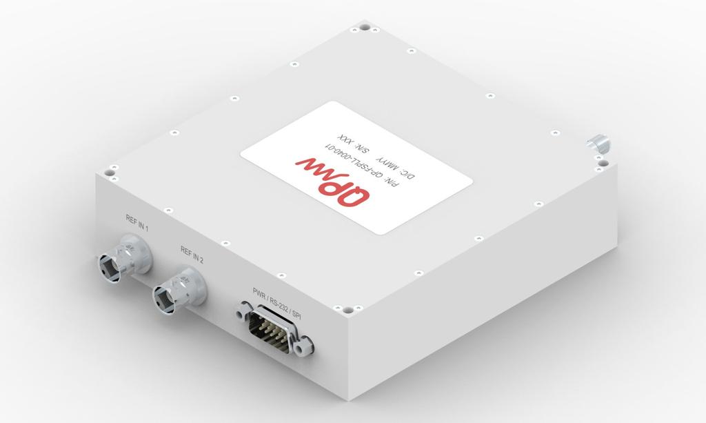
1 MICROWAVE FREQUENCY SYNTHESIZER QP-FSPLL USER MANUAL The QP-FSPLL is a low-phase noise wideband synthesizer operating from 50 MHz to 40 GHz with a nominal output power of +15 dbm. The synthesizer has a very stable internal reference and accepts 10MHz/100MHz external reference (auto-selectable), it includes a Jitter Attenuator. In addition to the RF output, it provides 2 programmable outputs, one in single-ended mode (LVCMOS) and one in differential or single-ended modes. Reference differential output is voltage programmable (1.8, 2.5 and 3.3 V) and reference single-ended output level is 3.3 V). The synthesizer has two operation modes. The "Fast Mode" provides a very fast switching frequency (as low as 30 µs). The standard mode provides very accurate frequency (0.05Hz). The frequency change can be controlled optionally using external Latch In (logic level triggered). Latch Out will change when frequency is ready to be changed (pulse). Its supply voltage is +7 V with typical consumption of 15 W and it can be configured and operated using USB 2.0, Ethernet (10BaseT), SPI and RS232. The wide temperature operating range from -20 ºC to 70 ºC, the IP67 sealing and the ruggedized connections make it suitable for both laboratory and harsh environments. Features RF OUTPUT: FREQUENCY RANGE FREQ. Fout<3 GHz SWITCHING TIME OUTPUT POWER OUTPUT RETURN LOSS HARMONIC LEVEL* SUBHARMONIC LEVEL SPURIOUS LEVEL PHASE NOISE**: * Up to 20 GHz 50 MHz - 40 GHz 0.05 Hz (STANDARD MODE) or 3 Hz (FAST MODE) 80 µs (STANDARD MODE) or 30 µs (FAST MODE) +15 dbm 14 db -30 dbc -30 dbc -60 dbc DIGITAL OUTPUT: FREQUENCY RANGE REF OUT_1 REF OUT_2 300 khz MHz SINGLE-ENDED: LVCMOS DIFFERENTIAL: LVPECL, LVDS, HCSL 2x SINGLE-ENDED: LVCMOS ENVIROMENTAL RATING TEMPERATURE RANGE -20ºC TO 70ºC IP RATING GHz 1KHz -114 dbc/hz -102 dbc/hz -89 dbc/hz -83 dbc/hz -77 dbc/hz 10KHz -120 dbc/hz -103 dbc/hz -91 dbc/hz -85 dbc/hz -79 dbc/hz 100KHz -118 dbc/hz -109 dbc/hz -97 dbc/hz -91 dbc/hz -85 dbc/hz 1MHz -136 dbc/hz -131 dbc/hz -119 dbc/hz -113 dbc/hz -107 dbc/hz 10MHz -165 dbc/hz -139 dbc/hz -127 dbc/hz -121 dbc/hz -115 dbc/hz

2 PHASE NOISE DATA: ** Typical values
3 Drawings
4 Dimensions Note: Specifications and ordering information are subject to change without notice.
5 Connection Specifications Front view: RF OUT (2.92mm-F) CTRL USB MICRO B Receptacle ETHERNET RJ45 USB PORT MINI B Receptacle REF OUT1 FREQUENCY OUTPUT (SMA-F) AUX2, AUX3 SINGLE/DIFFERENTIAL (2xSMA-F) Rear view: REF IN1 10MHz (BNC) REF IN2 100MHz (BNC ) DE-15 Male POWER / SPI / RS232 CONNECTOR Connectors: REF IN1 BNC External Reference Input for 10 MHz (+5 ± 10 dbm) 1 REF IN2 BNC External Reference Input for 100 MHz (+5 ± 10 dbm) 2 RF OUT 2.92mm-F connector. Frequency Output, connector for Synthesizer Frequency Output. Range from 50 MHz to 40 GHz AUX1 SMA (F) connector programmable Output reference single-ended LVCMOS. Range from 300 KHz to 700 MHz. +5 ±2dBm. Voltage programmable (1.8, 2.5, 3.3, and 5 V) (Default: 100Mhz) AUX2, AUX3 Two 2 SMA (F) connectors for a full programmable differential output. Voltage programmable (1.8, 2.5 and 3.3 V) and format programmable (LVPECL, LVDS, HCLS, LVCMOS). Range from 300 KHz to 700 MHz. +5 ±2 dbm. (Default: 100 MHz) USB PORT USB Mini B receptacle (USB 2.0) for communicate Synthesizer with PC application CTRL USB Reserved for future control of external devices ETHERNET Ethernet connector (10BaseT, RJ45). For communicate Synthesizer with PC application using LAN infrastructure. If you need to use more than one synthesizer at the same time, use this protocol. Assign different IP address to each one and connect (in the same LAN)
6 EXT CONNECTOR DE-15 Male connector for power supply, SPI, RS232, lock detect, latch in and latch out. 1, 2 The reference is selected automatically when connected in the order of priority: 1) REF IN2, 2) REF IN, 3) Internal Reference. External connector pinout: PIN NAME PIN NAME 1 PWR 9 GND 2 PWR 10 TX 3 Latch_Out 11 PWR 4 SSE 12 Latch_In 5 MISO 13 MOSI 6 PWR 14 SCK 7 GND 15 RX 8 GND General Power Supply PWR Power supply: 7 V, 15 W GND Common ground SPI Port 3 MOSI (In) Master Output Slave Input. Data is read on rising edge of SCK MISO (Out) Master Input Slave Output. Data output is valid on the falling edge of SCK SCK (In) SPI Clock (Max. 4 MHz clock speed) SSE (In) Slave Select Enable. Active-Low Slave Select GND SPI port common ground 3 The maximum operating voltage admitted in SPI port is 5 V. It also accepts 3.3 V levels. RS232 Serial Port 4 TX Transmit RX Receive GND RS232 common ground Communication Parameters Baud=115200, Data size=8 bit, Parity=None, Stop Bits=1. No handshake 4 Port has RS232 voltage levels (not TTL). Latch Latch_In Latch_Out Lock LOCK (out) Trigger input for frequency change. The frequency change is made when there is logic level zero in this entry (or NC). If the input is logic one, no frequency change will occur Output frequency change. When frequency command is received this output generates a positive pulse when synthesizer is ready to change the frequency. Only then Latch_In should be triggered. Logic levell equal to one while PLL is locked, zero in other case. During SPI transmission between microcontroller and PLL the state can vary due to shared pin
7 Synthesizer Installation USB port Steps: Step 1 Step 2 Step 3 Step 4 Step 5 Connect the synthesizer to PC using USB port. See Image USB Connection below Run the application Synthesizer.exe Select the desired options in Settings Tab (see Settings Tab example) Click on Configure button. Configuration will not be lost after turn off the synthesizer Click on USB Tab to define desired frequency of operation and other parameters (see USB Tab example) USB Connection: Synthesizer Front Synthesizer Rear RF Signal Output USB port Computer DE-15 Connections: Mandatory Optional Lock + PWR - GND Latch In & Latch Out ETHERNET port Steps: Step 1 Step 2 Step 3 Step 4 Step 5 Step 6 Step 7 Step 8 Connect the synthesizer to PC using USB port Run the application Synthesizer.exe Select the desired options in Settings Tab (see Settings Tab example) Enter the Local IP (this is the IP assigned to PC Ethernet or Wireless interface) Enter the Synthesizer IP (should be an unused IP), the network mask, and default gateway. The synthesizer does not support DHCP protocol Click on Configure button. Configuration will not be lost after turn off the synthesizer Disconnect Synthesizer from PC USB port and connect Ethernet cable. Click on Ethernet Tab to define desired frequency of operation and other parameters (see Ethernet Tab example)
: Step 1 Step 2 Connect the synthesizer to the PC (or another system) trough selected protocol. (SPI @ 3.")
8 Ethernet Connections: Synthesizer Front RF Signal Output Synthesizer Rear LAN Router/Switch/Hub DE-15 Connections: Mandatory Optional Ethernet Ports PC Ethernet port Computer Lock + PWR - GND Latch In & Latch Out External connector (SPI & RS32 ports): Step 1 Step 2 Connect the synthesizer to the PC (or another system) trough selected protocol. 3.3 or 5 V, ±12 V) Send the desired frequency or command (as described in Operation Commands section) RS232 Connections: Synthesizer Front Synthesizer Rear RF Signal Output Computer USB port RS232 Connector or USB to RS232 to converter RS232 RX RS232 TX GND DE-15 Connections: Mandatory Optional Lock + PWR - GND Latch In & Latch Out TX RX
9 SPI Connections: Synthesizer Front RF Signal Output Synthesizer Rear SPI Master Controller PC Application MOSI MISO SCK SSE GND Mandatory DE-15 Connections: Optional Lock + PWR - GND Latch In & Latch Out MOSI SSE MISO GND SCK The PC application does not need to be installed. It can run from any path or directory. Execute Synthesizer.exe. Settings tab is always opened by default. Following is a review of the different tabs of the application: Settings Tab Description This tab has different options. It can be selected the function mode of the synthesizer (Standard or Fast) and set the network configuration data. The differential output can enabled or disabled and the frequency can be configured, in addition to format, voltage and impedance. Information about the different outputs can be seen clicking the button. The XXXXXX button send all the previous parameters configured in this tab to the synthesizer through USB. The button will restore the parameters of the synthesizer to default state and all data previously stored in the synthesizer will be lost. Settings Tab example: Mode Standard Differential Output (REF OUT2) Enabled, Frequency: 1 MHz Voltage: 3.3 V Impedance: 22 Ω Local IP Synthesizer Network Config IP: Subnet Mask: Gateway: The attached image shows the configuration in the Settings tab.
10 Steps: 1 Insert all the configuration data properly and select the desired options 2 Ensure synthesizer is connected through USB (USB cable with green check symbol at top right) 3 Finally click on button to send the data Calibration Description Use this section to calibrate the frequency of the synthesizer. This section is password protected. The Change Passwo button allows to change the password. See Change Password example below. Default factory password is The frequency offset can be restarted with the Reset Offset button. Tha maximum positive frequency offset value is Hz and the minimum negative frequency offset is Hz. Calibration example: Frequency Offset Set a frequency offset of Hz
 box. 10534.79 Hz is introduced in this example. 5 Click on CALIBRATE button.")

11 Steps: 1 Insert a valid password and click on Accept. 2 Click the button SEND. to set a frequency of 1500 MHz. 3 Measure the frequency offset with a high precision frequency meter. 4 Introduce the offset necessary to adjust the frequency in the Frequency Offset Adjust (+/-) box Hz is introduced in this example. 5 Click on CALIBRATE button Password Change the password using the Change Password button. Steps: 1 Introduce a valid old password, introduce a new password and repeat it. Click on Accept. 2 Click the button SEND. to change the password 1 2 Note: If you lose the password you can download the application again with the default factory password. Note 2: The maximum password size is 8 chars.
12 USB Tab Description Use this tab to manage the synthesizer from USB port. In this tab, the RF OUT frequency can be configured. The lock state can also be checked. The frequency can be introduced in the FREQUENCY box, it can also be changed with the arrows or using the mouse wheel. The Change S button set the frequency change step, value can be introduced in the box, changed with the arrows or the mouse wheel. USB Tab example, Normal Mode: Frequency Set frequency of RF OUT to MHz. Steps: 1 Introduce the frequency in the FREQUENCY box. 2 Click the button SEND. 3 After step 2, the Lock state of the PLL can be checked clicking on the button CHECK. If the PLL is locked, the circle turns green. If not, it turns red. Grey means lock state is not checked
13 USB Tab example, Sweep Mode: Sweep Sweep Mode settings: frequency out from 1 GHz to 40 GHz with a step of 500 MHz, 2 sweeps, Up Down mode and dwell time of 10 ms. Steps: 1 Introduce the sweep configuration. 2 Click the button configu. 3 After step 2, the config is loaded in Synthesizer so now the button can be clicked to initiate the sweep Note: The external Latch can be used to latch the sweep after step 3.
14 Ethernet Tab Description Use this tab to manage the synthesizer from Ethernet (LAN) port. In this tab, the RF OUT frequency can be set. The lock state can also be checked. The frequency can be introduced in the FREQUENCY box, it can also be changed with the arrows or using the mouse wheel. The Change S button set the frequency change step, value can be introduced in the box, changed with the arrows or the mouse wheel. Ethernet Tab example, Normal Mode: Frequency Set frequency of RF OUT to MHz. Steps: 1 Introduce the frequency in the FREQUENCY box. 2 Click the button SEND. 3 After step 2, the Lock state of the PLL can be checked clicking on the button CHECK L If the PLL is locked, the circle turns green. If not, it turns red. Grey means lock state is not checked

15 Ethernet Tab example, Sweep Mode: Sweep Sweep frequency settings are: frequency out from 1 GHz to 20 GHz in 2000 points, continuous sweep mode,up Down mode, and dwell time of 100 ms. Steps: 1 Introduce the sweep configuration. 2 Click the button configu. 3 After step 2, the config is loaded in Synthesizer so now the button can be clicked to initiate the sweep. 4 Click on Stop to stop the sweep /4 Note: The external Latch can be used to latch the sweep after step 3.
16 Communication Specifications NOTE: It is recommended to use only one protocol to control the synthesizer at the same time. Mixing protocols (e.g.: Ethernet and RS232) can produce unknown effects. NOTE 2: A delay of 2ms should be between commands. RS232 Command syntax The syntax of the commands is Command name + Optional Parameters (if required) + Carriage Return char. ASCII code is used List of operation commands: Frequency Change System Reset Send frq string followed by frequency value (in MHz) and followed by the Carriage Return char (Hex: 0x0D). ASCII code frq <cr> (To set MHz) Send rst string followed by the Carriage Return char (Hex: 0x0D). (ASCII code) rst<cr> IP PC Remote Send ipl followed by IP from PC that will be used to communicate with the device. The IP must be in hexadecimal value, not in ASCII. 4 bytes must be sent with values from 0 to 255 each one. Finally send the Carriage Return char. ASCII code + bytes ipl C0 A <CR> (To set ) IP Synthesizer Send ips followed by the IP used for communications with the device. The IP must be in hexadecimal value, not in ASCII. 4 bytes must be sent with values from 0 to 255 each one. Finally send the Carriage Return char. ASCII code + bytes ips C0 A8 01 C7 <CR> (To set ) Subnet Mask Send msk followed by the Subnet Mask used in the network and. The IP must be in hexadecimal value, not in ASCII. 4 bytes must be sent with values from 0 to 255 each one. Finally send the Carriage Return char. ASCII code + bytes msk FF FF FF 00 <CR> (To set ) Gateway Send gtw followed by the Gateway used in the network. The IP must be in hexadecimal value, not in ASCII. 4 bytes must be sent with values from 0 to 255 each one. Finally send the Carriage Return char. ASCII code gtw C0 A <CR> (To set ) Lock Send lck followed by a Carriage Return char to receive the Lock state of the PLL. ASCII code lck<cr>
17 Mode Standard Mode Fast Disable Differential Output Enable Differential Output Frequency Out REF OUT2 Differential Output Format Send mst followed by a Carriage Return char to configure the synthesizer in Standard Mode. ASCII code mst<cr> Send mfs followed by a Carriage Return char to configure the Synthesizer in Standard Mode. ASCII code mfs<cr> Send cg99 followed by a Carriage Return char to disable the Differential Output. ASCII code cg99<cr> Send cg00 followed by a Carriage Return char to disable the Differential Output. ASCII code cg00<cr> Send foc string followed by the frequency value (in MHz) and followed by the Carriage Return char (Hex: 0x0D). ASCII code foc <cr> (to set MHz) Send cg string followed by the number of the configuration desired (see next table) and the Carriage Return char (Hex: 0x0D). ASCII code cg11<cr> (to set LVCMOS 3,3 V, 22 Ω (Phase)) Number Output Format 1 LVPECL 2 LVPECL (Low Power) 3 LVDS 1,8 V 4 LVDS 2,5 V 5 LVDS 3,3 V 6 LVDS 1.8 V (Low Power) 7 LVDS 2.5 V (Low Power) 8 LVDS 3.3 V (Low Power) 9 HCSL 1.8 V 10 HCSL 2.5 V or 3.3 V 11 LVCMOS (In Phase): 1,8 V, 31 Ω / 2,5 V, 24 Ω /3,3 V, 22 Ω 12 LVCMOS (In Phase): 2,5 V, 43 Ω / 3,3 V, 38 Ω 13 LVCMOS (In Phase): 2,5 V, 35 Ω / LVCMOS 3,3 V, 30 Ω 14 LVCMOS (Complementary): 1,8 V, 31 Ω / 2,5 V, 24 Ω 3,3 V, 22 Ω 15 LVCMOS (Complementary): 2,5 V, 43 Ω / 3,3 V, 38 Ω 16 LVCMOS (Complementary): 2,5 V, 35 Ω / 3,3 V, 30 Ω Differential Output Voltage 1.8 V Differential Output Voltage 2.5 V Send vo1 followed by a Carriage Return char to set Differential Output with 1.8 V. ASCII code vo1<cr> Send vo2 followed by a Carriage Return char to set Differential Output with 2.5 V. ASCII code vo2<cr>
18 Differential Output Voltage 3.3 V Send vo3 followed by a Carriage Return char to set Differential Output with 3.3 V. ASCII code vo3<cr> Sweep Mode Configuration 1 2 Option INITIAL_FREQ FINAL _FREQ REPETITTIONS POINTS_STEP MODE DWELL_TIME Start Sweep Stop Sweep Send swp followed by the desired options. Use the table to set the command. All the variables are mandatory. The command is swpinitial_freq_*final _FREQ *REPETITTIONS*POINTS_STEP*MODE* Description Any valid frequency from 50MHz to (MHz) It should be smaller than FINAL_FREQ Any valid frequency from 50MHz to (MHz) It should be greater than INITIALL_FREQ 0 for continuous mode, a number between 1 and to choose the repetitions. A number to choose the step frequency in MHz (Max 5000MHz) or p followed by the number of points desired between the INITIAL_FREQ and the FINAL_FREQ. 0 UP Mode, 1 DOWN Mode, 2 UP DOWN Mode Dwell time in ms,0 for minimum dwell time, maximum dwell time is 65535ms. swp1000*35000*0*p2000*2*100<cr> (to set a sweep from 1GHz to 35GHz, continuous mode, 2000 points, Up Down mode and Dwell time 100ms swp50*3000*10*50*0*0 (to set a sweep from 50MHz to 3GHz, 10 repetitions, step of 50MHz, Up mode and minimum Dwell time. Send sts followed by a Carriage Return char to start the sweep previously configured. ASCII code sts<cr> Send sps followed by a Carriage Return char to stop an ongoing sweep. ASCII code sps<cr>
19 SPI Command syntax Same commands as RS232. Hexadecimal ASCII values of commands must be sent SPI Timing: Operation command examples: Frequency Change System Reset IP PC Remote Send hexadecimal values of frq string followed by hexadecimal values of frequency (in MHz) and a Carriage Return char in hexadecimal (0x0D). Hexadecimal values are equivalent to chars in ASCII code E D (to set MHz) Send string rst followed by Carriage Return (0x0D) in hexadecimal ASCII equivalent D Send hexadecimal values of ipl string followed by IP from PC that will be used to communicate with the device. The IP must be in hexadecimal value, not in ASCII. 4 bytes must be sent with values from 0 to 255 each one. Finally send the Carriage Return char C C0 A D (to send ipl <cr> ) Note: Do not send SPI commands until Synthesizer is powered on during 5 seconds. DocRev 1.13
MTS2500 Synthesizer Pinout and Functions
 MTS2500 Synthesizer Pinout and Functions This document describes the operating features, software interface information and pin-out of the high performance MTS2500 series of frequency synthesizers, from
Models FSW-0010 FSW-0020
 MICROWAVE FREQUENCY SYNTHESIZERS Features: 0.1 to 10 GHz and 0.2 to 20 GHz Coverage 0.001 Hz Resolution Power Calibration and Control 100 μs Frequency Switching Instrument-Grade Spectral Purity QuickSyn
QuickSyn Lite mmw Frequency Synthesizer
 FSL-2740, FSL-5067, FSL-7682 Features mmw frequency Fast switching speed Low phase noise Reference locking of multiple modules Soft front panel Frequency sweep & 32K-point LIST mode Interfaces: USB & SPI
QuickSyn Frequency Synthesizers
 QuickSyn Frequency Synthesizers FSL mmw Series This series offers models FSL-2740, FSL-5067, and FSL-7682, which extend QuickSyn Lite synthesizers into the millimeterwave range. The three available models
QuickSyn Frequency Synthesizers
 QuickSyn Frequency Synthesizers The QuickSyn Advantage Our popular line of QuickSyn frequency synthesizers delivers instrumentgrade performance up to 82 GHz, increased functionality, and efficient power
Model 745 Series. Berkeley Nucleonics Test, Measurement and Nuclear Instrumentation since Model 845-M Specification 1.8 BNC
 Specification 1.8 Model 745 Series 0.01-20.0 GHz Low Phase Noise Synthesizer 250 fs Digital Delay Generator Berkeley Nucleonics Test, Measurement and Nuclear Instrumentation since 1963 Introduction The
SIGNAL GENERATORS. MG3633A 10 khz to 2700 MHz SYNTHESIZED SIGNAL GENERATOR GPIB
 SYNTHESIZED SIGNAL GENERATOR MG3633A GPIB For Evaluating of Quasi-Microwaves and Measuring High-Performance Receivers The MG3633A has excellent resolution, switching speed, signal purity, and a high output
Model 745 Series. Berkeley Nucleonics Test, Measurement and Nuclear Instrumentation since Model 845-HP Datasheet BNC
 Model 845-HP Datasheet Model 745 Series Portable 20+ GHz Microwave Signal Generator High Power +23dBM Power Output 250 fs Digital Delay Generator BNC Berkeley Nucleonics Test, Measurement and Nuclear Instrumentation
R5 RIC Quickstart R5 RIC. R5 RIC Quickstart CONTENTS. Saab TransponderTech AB. Appendices. Project designation. Document title
 Appendices 1 (10) Project designation R5 RIC Document title CONTENTS 1 Installation... 2 1.1 Connectors... 2 1.1.1 Power... 2 1.1.2 Video... 2 1.1.3 Sync... 3 1.1.4 RS232/ARP/ACP... 3 1.1.5 Radar data...
Model 855 RF / Microwave Signal Generator
 Features Very low phase noise Fast switching Phase coherent switching option 2 to 8 phase coherent outputs USB, LAN, GPIB interfaces Applications Radar simulation Quantum computing High volume automated
GPS Time and Frequency Reference Receiver
 $ GPS Time and Frequency Reference Receiver Symmetricom s 58540A GPS time and frequency reference receiver features: Eight-channel, parallel tracking GPS engine C/A Code, L1 Carrier GPS T-RAIM satellite
Signal Forge. Signal Forge 1000 TM Synthesized Signal Generator. Digital and RF Tester with 1 GHz Range. Key Features
 Signal Forge TM Signal Forge 1000 TM Synthesized Signal Generator L 8.5 W 5.4 H 1.5 Digital and RF Tester with 1 GHz Range The Signal Forge 1000 combines a 1 GHz frequency range with three dedicated outputs
3 GHz to 6 GHz Frequency Synthesizer
 3 GHz to 6 GHz Frequency Synthesizer Low Phase Noise in a Lower Cost Package Features API Technologies Model LCFS1063 frequency synthesizer combines a monolithic integer-n microwave synthesizer, a reference
Model 845-M Low Noise Synthesizer
 Model 845-M Low Noise Synthesizer Features Low phase noise Fast switching down to 20 µs FM, Chirps, Pulse Internal OCXO, external variable reference Single DC supply Applications ATE LO for frequency converters
Model 865-M Wideband Synthesizer
 Model 865-M Wideband Synthesizer Features Wideband Low phase noise Fast switching down to 20 µs FM, Chirps, Pulse Internal OCXO, external variable reference Single DC supply Applications ATE LO for frequency
DS H01 DIGITAL SYNTHESIZER MODULE SYSTEM SOLUTIONS. Features Applications 174 x 131 x 54 mm. Technical Description
 DS H01 The DS H01 is a high performance dual digital synthesizer with wide output bandwidth specially designed for Defense applications where generation of wideband ultra-low noise signals along with very
Operating Instructions
 6 18 GHz Frequency Synthesizer PFS-618-CD-1 Operating Instructions 1) Frequency Control The Frequency Control Code is constructed of 17 bits (A0 - A16). The following equation and table describe the frequency
Stensat Transmitter Module
 Stensat Transmitter Module Stensat Group LLC Introduction The Stensat Transmitter Module is an RF subsystem designed for applications where a low-cost low-power radio link is required. The Transmitter
APPH6040B / APPH20G-B Specification V2.0
 APPH6040B / APPH20G-B Specification V2.0 (July 2014, Serial XXX-XX33XXXXX-XXXX or higher) A fully integrated high-performance cross-correlation signal source analyzer for to 7 or 26 GHz 1 Introduction
Signal Forge 2500M Frequency Expansion Module. 1.5 GHz to 2.6 GHz. User Manual
 TM TM Signal Forge 2500M Frequency Expansion Module 1.5 GHz to 2.6 GHz User Manual Technical Support Email: Support@signalforge.com Phone: 512.275.3733 x2 Contact Information Web: www.signalforge.com Sales
User s Manual V1.4. Signal Generator Models BENCHTOP MICROWAVE SOURCE, COMPACT SIGNAL GENERATOR, COMPACT SYNTHESIZER
 User s Manual V1.4 Signal Generator Models BENCHTOP MICROWAVE SOURCE, COMPACT SIGNAL GENERATOR, COMPACT SYNTHESIZER WARRANTY Berkeley Nucleonics Corporation warrants all instruments, including component
Radar transponders. WORK Microwave GmbH Raiffeisenstrasse Holzkirchen Germany
 Radar transponders WORK Microwave GmbH Raiffeisenstrasse 12 83607 Holzkirchen Germany Tel. Fax E-Mail +49 8024 6408 0 +49 8024 6408 40 sales@work-microwave.com Table of Contents 1 Introduction... 3 1.1
2400C Series Microwave Signal Generators 10 MHz to 40 GHz. Preliminary Technical Datasheet. Low Phase Noise and Fast-Switching Speed in a Single Unit
 Preliminary Technical Datasheet 2400C Series Microwave Signal Generators 10 MHz to 40 GHz Low Phase Noise and Fast-Switching Speed in a Single Unit 2400C Series Microwave Signal Generator Signal Generator
Signal Forge. Signal Forge 1000 TM Synthesized Signal Generator. Flexible Design Enables Testing of RF and Clock-driven Systems.
 Signal Forge TM Signal Forge 1000 TM Synthesized Signal Generator L 8.5 W 5.4 H 1.5 Flexible Design Enables Testing of RF and Clock-driven Systems The Signal Forge 1000 combines a 1 GHz frequency range
Specification RIGOL. 6 Specification
 Specification RIGOL 6 Specification This chapter lists the specifications and general specifications of the analyzer. All the specifications are guaranteed when the following conditions are met unless
Model 865 RF / Ultra Low Noise Microwave Signal Generator
 Model 865 RF / Ultra Low Noise Microwave Signal Generator Features Excellent signal purity: ultra-low phase noise and low spurious Combination of highest output power and fastest switching Powerful touch-display
Model 865-M Wideband Synthesizer
 Model 865-M Wideband Synthesizer Features Wideband Low phase noise Fast switching down to 15 µs FM, Chirps, Pulse Internal OCXO, external variable reference Single DC supply Applications ATE LO for frequency
Phone:
 Email: Support@signalforge.com Phone: 512.275.3733 Web: www.signalforge.com Customer Service Email: Sales@signalforge.com Phone: 512.275.3733 Fax: 512.275.3735 Address: Signal Forge, LLC 2115 Saratoga
Model 7000 Series Phase Noise Test System
 Established 1981 Advanced Test Equipment Rentals www.atecorp.com 800-404-ATEC (2832) Model 7000 Series Phase Noise Test System Fully Integrated System Cross-Correlation Signal Analysis to 26.5 GHz Additive
Rubidium Frequency Standard Model AR133A Ruggedized Low Profile
 Ruggedized Low Profile Key Features Long-term-stability: 5E-11/month 2E-12 frequency accuracy & 100nSec 1PPS accuracy relative to 1PPS input when disciplined Short term stability: 5E-12 @ 100s Phase noise:
Instruction Manual Model Ka-Band Block Upconverter
 Instruction Manual Model 4115-300 Ka-Band Block Upconverter Weather Resistant Unit November 2015, Rev. H Data, drawings, and other material contained herein are proprietary to Cross Technologies, Inc.,
Rubidium Frequency Standard Model AR133A Ruggedized Low Profile
 Rubidium Frequency Ruggedized Low Profile Key Features Long-term-stability: 5E-11/month Short term stability: 2E-12 @ 1000s (Typ.) Phase noise: -158 dbc/hz @10kHz Spurious: < -110 dbc Time Accuracy (1PPS):
MG3740A Analog Signal Generator. 100 khz to 2.7 GHz 100 khz to 4.0 GHz 100 khz to 6.0 GHz
 Data Sheet MG3740A Analog Signal Generator 100 khz to 2.7 GHz 100 khz to 4.0 GHz 100 khz to 6.0 GHz Contents Definitions, Conditions of Specifications... 3 Frequency... 4 Output Level... 5 ATT Hold...
3 GHz Carrier Backhaul Radio. Model: AF-3X. Tel: +44 (0) Fax: +44 (0) LINK GPS MGMT DATA DATA
 Fax: +44 (0) LINK GPS MGMT DATA DATA") LINK GPS MGMT DATA DATA MGMT GPS LINK 3 GHz Carrier Backhaul Radio Model: AF-3X LINK GPS MGMT DATA 3 GHz Carrier Backhaul Radio Model: AF-3X LINK GPS MGMT DATA DATA MGMT GPS LINK Introduction Thank you
LINK GPS MGMT DATA DATA MGMT GPS LINK 3 GHz Carrier Backhaul Radio Model: AF-3X LINK GPS MGMT DATA 3 GHz Carrier Backhaul Radio Model: AF-3X LINK GPS MGMT DATA DATA MGMT GPS LINK Introduction Thank you
X-Band QTRM Product Capability QTRM - Quad Transmit Receive Module (4-Channel T/R Module)
") MAIA-009446-000000 X-Band QTRM Product Capability QTRM - Quad Transmit Receive Module (4-Channel T/R Module) RS485 Half-Duplex, 5.0 Mbps serial data bus for control and monitoring. DSP externally programmable
MAIA-009446-000000 X-Band QTRM Product Capability QTRM - Quad Transmit Receive Module (4-Channel T/R Module) RS485 Half-Duplex, 5.0 Mbps serial data bus for control and monitoring. DSP externally programmable
THE PHS 8340 FAMILY OF HIGH VALUE BROADBAND MICROWAVE SYNTHESIZERS
 SUBTITLE THE PHS 8340 FAMILY OF HIGH VALUE BROADBAND MICROWAVE SYNTHESIZERS BENCHTOP Multi Output MODULAR HANDHELD The PHS 8340 Family SUBTITLE Features: Standard Range: 700 MHz to 18 GHz Extendable to
NetPage Network Wireless Paging System (POCSAG) NP-14 Series. Operation Manual CCW
 NP-14 Series. Operation Manual CCW") NetPage Network Wireless Paging System (POCSAG) NP-14 Series Operation Manual CCW152241-002 1 INTRODUCTION The NP-14 Network wireless paging system is a fully-programmable, single-board, POCSAG encoder
NetPage Network Wireless Paging System (POCSAG) NP-14 Series Operation Manual CCW152241-002 1 INTRODUCTION The NP-14 Network wireless paging system is a fully-programmable, single-board, POCSAG encoder
SDI SPECTRADYNAMICS, INC. LOW NOISE FREQUENCY SYNTHESIZER LNFS-400 OPERATING MANUAL
 SPECTRADYNAMICS, INC. LOW NOISE FREQUENCY SYNTHESIZER LNFS-400 OPERATING MANUAL SPECTRADYNAMICS, INC 1849 Cherry St. Unit 2 Louisville, CO 80027 Phone: (303) 665-1852 Fax: (303) 604-6088 www.spectradynamics.com
EVDP610 IXDP610 Digital PWM Controller IC Evaluation Board
 IXDP610 Digital PWM Controller IC Evaluation Board General Description The IXDP610 Digital Pulse Width Modulator (DPWM) is a programmable CMOS LSI device, which accepts digital pulse width data from a
INSTRUMENTS, INC. Models 2960AR and 2965AR Disciplined Rubidium Frequency Standards. Section Page Contents
 INSTRUMENTS, INC. Models 2960AR and 2965AR Disciplined Rubidium Frequency Standards 2960AR 2965AR Section Page Contents 1.0............................. 2......................... Description 2.0.............................
Signal Forge 1800M Frequency Expansion Module. 1.0 GHz to 1.8 GHz. User Manual
 TM TM Signal Forge 1800M Frequency Expansion Module 1.0 GHz to 1.8 GHz User Manual Technical Support Email: Support@signalforge.com Phone: 512.275.3733 x2 Contact Information Web: www.signalforge.com
Instruction Manual Model 4116-T51 Multi-Band Translator
 Instruction Manual Model 4116-T51 Multi-Band Translator Weather Resistant Unit March 2015, Rev. F Data, drawings, and other material contained herein are proprietary to Cross Technologies, Inc., but may
GHz UPCONVERTER TESTING TABLE. 2.3GHz Out-Band ( GHz) Spurious. Level (dbc) min
 Spurious. Level (dbc) min") HIGH PEAK TO AVERAGE RATIO OFDM BLOCER IF RF Output IF input range 25MHz~800HMz 2.30GHz~ 25MHz~200MHz (RFBUC2G3GA) 200MHz~800MHz (RFBUC2G3GB) Summary up-converter unit uses the phase lock technology, and
HIGH PEAK TO AVERAGE RATIO OFDM BLOCER IF RF Output IF input range 25MHz~800HMz 2.30GHz~ 25MHz~200MHz (RFBUC2G3GA) 200MHz~800MHz (RFBUC2G3GB) Summary up-converter unit uses the phase lock technology, and
Agilent ESA-L Series Spectrum Analyzers
 Agilent ESA-L Series Spectrum Analyzers Data Sheet Available frequency ranges E4403B E4408B 9 khz to 1.5 GHz 9 khz to 3.0 GHz 9 khz to 26.5 GHz As the lowest cost ESA option, these basic analyzers are
FMSN3902 DATA SHEET. USB Frequency Synthesizer PLL (Phase Locked Loop), Operating From 5 GHz to 10 GHz With SMA Output. Features: Applications:
, Operating From 5 GHz to 10 GHz With SMA Output. Features: Applications:") USB Frequency Synthesizer PLL (Phase Locked Loop), Operating From 5 GHz to 10 GHz With SMA Output FMSN3902 is a Frequency Synthesizer Module that covers a wide frequency band from 5 GHz to 10 GHz with
USB Frequency Synthesizer PLL (Phase Locked Loop), Operating From 5 GHz to 10 GHz With SMA Output FMSN3902 is a Frequency Synthesizer Module that covers a wide frequency band from 5 GHz to 10 GHz with
GFT1012 2/4 Channel Precise Slave Generator
 Features Two Independent Delay Channels (Four channels available as an option) 1 ps Time Resolution < 5 ps RMS Jitter (Slave-to-Slave) < 6 ps / C Drift (Slave-to-slave) 1 Second Range Output Pulse Up to
THE PHS 8500 FAMILY OF VERY LOW PHASE NOISE HIGH PERFORMANCE MICROWAVE SYNTHESIZERS BENCHTOP
 SUBTITLE THE PHS 8500 FAMILY OF VERY LOW PHASE NOISE HIGH PERFORMANCE MICROWAVE SYNTHESIZERS BENCHTOP MODULAR HANDHELD The PHS 8500 Family SUBTITLE Features: Standard Range : 700 MHz to 18 GHz Extendable
SonoLab Echo-I User Manual
 SonoLab Echo-I User Manual Overview: SonoLab Echo-I is a single board digital ultrasound pulse-echo solution. The system has a built in 50 volt high voltage generation circuit, a bipolar pulser, a transmit/receive
11 GHz FDD Licensed Backhaul Radio. Model: AF 11FX
 11 GHz FDD Licensed Backhaul Radio Model: AF 11FX 11 GHz FDD Licensed Backhaul Radio Model: AF 11FX Introduction Thank you for purchasing the Ubiquiti Networks airfiber AF 11FX. This Quick Start Guide
INSTRUMENTS, INC. INSTRUCTION MANUAL Precision 350 MHz Synthesizer. Model 425A. Table of Contents. Section Page Contents
 INSTRUMENTS, INC. INSTRUCTION MANUAL Precision 350 MHz Synthesizer Model 425A Table of Contents Section Page Contents 1.0............................. 2......................... Description 2.0.............................
R&S SMB100N SIGNAL GENERATOR
 R&S SMB100N SIGNAL GENERATOR PERFORMANCE SPECIFICATIONS VERSION 02.00, SEPTEMBER 2009 CONTENTS Specifications...3 Definitions... 3 RF performance... 4 Frequency... 4 Frequency sweep... 4 Reference frequency...
15 Summary. Electrical Specifications. RF output Frequency. Out-Band Spurious. Mechanical and Environmental Specifications. Mechanical shock MTBF
 HIGH PEAK TO AVERAGE RATIO NVERTER IF Input 25MHz~800HMz RF Output t 14.85GHz~15.35GHz 15 Summary up-converter unit uses the phase lock technology, and it uses the crystal oscillator with temperature compensating
Multi-Channel RS-232 Serial RF Transceiver
 RF-232 Multi-Channel RS-232 Serial RF Transceiver The RF-232 subassembly is a multi-channel serial radio transceiver. This device accepts and outputs standard serial data at one of three selectable data
2026Q CDMA/GSM Interferer MultiSource Generator
 Signal Sources 2026Q CDMA/GSM Interferer MultiSource Generator The 2026Q is designed to work with a radio test set to provide a fully integrated radio receiver test solution for cellular and PCS systems
HS9000 SERIES. RoHS. Multi-Channel RF Synthesizers
 The Holzworth HS9000 Series multi-channel platform is designed to achieve optimal channel-tochannel stability across all integrated channel synthiesizers via a conductively cooled, fan-less enclosure.
TRANSCEIVER FSK. Version: 434 MHz Band / 868 MHZ Band / Code: / A
 TRANSCEIVER FSK Version: 434 MHz Band / 868 MHZ Band / Code: 3-2000519 / 3-2000519A DESCRIPTION: The 3-2000519 and 3-2000519A modules are fully programmable multichannel PLL based FSK transceivers, with
Agilent E4428C ESG Analog Signal Generator
 Migrate to the new Agilent MXG X-Series signal generator and generate true performance The new MXG exceeds the ESG s performance in every category - output power, phase noise, spurious, and low frequency
20 CHANNELS DIGITAL DELAY GENERATOR
 NUT 063 Ed. 2.2 September 2015 User's Manual MODEL 745-20C 20 CHANNELS DIGITAL DELAY GENERATOR 20 independent delay channels 100 ps delay resolution (1 ps option) 10 seconds delay range Adjustable output
SDI SPECTRADYNAMICS, INC.
 SPECTRADYNAMICS, INC. Low Noise Frequency Synthesizer LNFS-400 Operating Manual SPECTRADYNAMICS, INC 1849 Cherry St., Unit 2 Louisville, CO 80027 Phone: (303) 665-1852 Fax: (303) 604-6088 Table of Contents
RF Wireless Serial Device Server
 RF-SDS RF Wireless Serial Device Server The RF-SDS subassembly is a radio transceiver acting as a Serial Device Server, which externally connects a remote serial RF transceiver to an Ethernet network (TCP/IP).
G3P-R232. User Manual. Release. 2.06
 G3P-R232 User Manual Release. 2.06 1 INDEX 1. RELEASE HISTORY... 3 1.1. Release 1.01... 3 1.2. Release 2.01... 3 1.3. Release 2.02... 3 1.4. Release 2.03... 3 1.5. Release 2.04... 3 1.6. Release 2.05...
This section lists the specications for the Agilent 8360 B-Series. generators, Agilent Technologies has made changes to this product
 2c Specifications This section lists the specications for the Agilent 8360 B-Series swept signal generator. In a eort to improve these swept signal generators, Agilent Technologies has made changes to
HS9000 SERIES. RoHS. Multi-Channel RF Synthesizers
 Holzworth has refined its multi-channel platform in the form of the HS9000 Series for integration of the HSM Series Single Channel Synthesizers. The HS9000 series is designed to achieve optimal channel-to-channel
PORTABLE WIDEBAND RF SIGNAL GENERATOR
 DS Instruments -Key Features- 25 to 6000MHz Coverage Calibrated RF Power Output SG6000L R11 PORTABLE WIDEBAND RF SIGNAL GENERATOR 31 RF Output Step Attenuator 20 Vernier Range USB COM Interface Industry
Frequency Stability dbc/hz/hour / Sweeping locking Time ms
 Summary CW and Analog High Power (+24dBm) Signal Generator 2-13GHz General Specification Frequency range 2 13GHz Output power: +24dBm max. Reverse power protection. Dynamitic power range: 28dB Sweeping
Spectrum Analyzers 2680 Series Features & benefits
 Data Sheet Features & benefits n Frequency range: 9 khz to 2.1 or 3.2 GHz n High Sensitivity -161 dbm/hz displayed average noise level (DANL) n Low phase noise of -98 dbc/hz @ 10 khz offset n Low level
PHASE-LOCKED OSCILLTOR TO 16 GHz PLO-SFSO/MFSO-B1-S/E/C
 Datasheet PHASE-LOCKED OSCILLTOR 1.925 TO 16 GHz TMYTEK s phase-locked oscillator is a pre-configured source suitable for any RF front-end systems. The SFSO and the MFSO series offers users the choice
Frequently Asked Questions DAT & ZX76 Series Digital Step Attenuators
 Frequently Asked Questions DAT & ZX76 Series Digital Step Attenuators 1. What is the definition of "Switching Control Frequency"? The switching control frequency is the frequency of the control signals.
RF Signal Generators. SG380 Series DC to 2 GHz, 4 GHz and 6 GHz analog signal generators. SG380 Series RF Signal Generators
 RF Signal Generators SG380 Series DC to 2 GHz, 4 GHz and 6 GHz analog signal generators SG380 Series RF Signal Generators DC to 2 GHz, 4 GHz or 6 GHz 1 µhz resolution AM, FM, ΦM, PM and sweeps OCXO timebase
Agilent 8360B Series Synthesized Swept Signal Generators 8360L Series Synthesized Swept CW Generators Data Sheet
 Agilent 8360B Series Synthesized Swept Signal Generators 8360L Series Synthesized Swept CW Generators Data Sheet 10 MHz to 110 GHz Specifications apply after full user calibration, and in coupled attenuator
DDS-PLL SYNTHESIZER DPL-2.5GF USER S MANUAL DIGITAL SIGNAL TECHNOLOGY, INC.
 DDS-PLL SYNTHESIZER DPL-2.5GF USER S MANUAL DIGITAL SIGNAL TECHNOLOGY, INC. 1-7-3, HIGASHI BENZAI, ASAKA CITY SAITAMA 351-22 JAPAN TEL : 81-48-468-694 FAX : 81-48-468-621 http://www.dst.co.jp/en 1 DPL-2.5GF
Agilent 33210A 10 MHz Function / Arbitrary Waveform Generator. User s Guide
 User s Guide Publication Number 33210-90001 (order as 33210-90000 manual set) Edition 1, August 2008 Copyright 2008 Agilent Technologies, Inc. Agilent 33210A 10 MHz Function / Arbitrary Waveform Generator
KU-BAND OUTDOOR BLOCK CONVERTERS
 Features/Options Low Phase Noise Exceeds IESS 308/309 25 db L-Band Gain Control with 0.1 db Step Auto Switch Over to an Internal High Stability REF Internal REF Tune to Match with External
SDI SPECTRADYNAMICS, INC GHZ RUBIDIUM FREQUENCY SYNTHESIZER OPERATING MANUAL
 SPECTRADYNAMICS, INC. 6.834 GHZ RUBIDIUM FREQUENCY SYNTHESIZER RB-1 OPERATING MANUAL SPECTRADYNAMICS, INC 1849 Cherry St. Unit 2 Louisville, CO 80027 Phone: (303) 665-1852 Fax: (303) 604-6088 www.spectradynamics.com
Instruction Manual Model
 Instruction Manual Model 2099-24 10MHz Source/Inserter, Redundant Power August 2016, Rev. 0 MODEL 2099 SOURCE / INSERTER ALARM DC ON REF ON LNB1 LNB2 MENU EXECUTE LNB1 +24.2V @ 0.249A LNB2 +23.8V @ 0.251A
APX Mobile and Portable Automated Test and Alignment
 APX Mobile and Portable Automated Test and Alignment Software Updates First things first! Be sure to check that you are running the latest software versions for the 8800SX and its applications. Visit the
Analog Arts SL987 SL957 SL937 SL917 Product Specifications [1]
![Analog Arts SL987 SL957 SL937 SL917 Product Specifications [1]](/thumbs/95/126095980.jpg "Analog Arts SL987 SL957 SL937 SL917 Product Specifications [1]") www.analogarts.com Analog Arts SL987 SL957 SL937 SL917 Product Specifications [1] 1. These models include: an oscilloscope, a spectrum analyzer, a data recorder, a frequency & phase meter, an arbitrary
www.analogarts.com Analog Arts SL987 SL957 SL937 SL917 Product Specifications [1] 1. These models include: an oscilloscope, a spectrum analyzer, a data recorder, a frequency & phase meter, an arbitrary
USER'S MANUAL. Model : K
 USER'S MANUAL Model : 2000-64K TM GINA MODEL 2000-64K Overview GINA Model 2000-64K is a stand-alone, high frequency data transceiver using spread spectrum technology. GINA 2000-64K capabilities include
LAX016 Series Logic Analyzer User Guide
 LAX016 Series Logic Analyzer User Guide QQ: 415942827 1 Contents I Overview... 4 1 Basic knowledge... 4 2 Product series... 4 3 Technical specification... 5 II Brief introduction to JkiSuite software...
LNS ultra low phase noise Synthesizer 8 MHz to 18 GHz
 LNS ultra low phase noise Synthesizer 8 MHz to 18 GHz Datasheet The LNS is an easy to use 18 GHz synthesizer that exhibits outstanding phase noise and jitter performance in a 3U rack mountable chassis.
ST600 TRANSMITTER OPERATING INSTRUCTIONS
 ST600 TRANSMITTER OPERATING INSTRUCTIONS 1892 1273 These operating instructions are intended to provide the user with sufficient information to install and operate the unit correctly. The Wood and Douglas
Vector Network Analyzers ZVB
 Specifications Version 05.00 Vector Network Analyzers ZVB September 2005 Specifications MEASUREMENT RANGE...3 MEASUREMENT SPEED...5 MEASUREMENT ACCURACY...6 EFFECTIVE SYSTEM DATA...8 TEST PORT OUTPUT...8
GPS10RBN-26: 10 MHz, GPS Disciplined, Ultra Low Noise Rubidium Frequency Standard
 GPS10RBN-26: 10 MHz, GPS Disciplined, Ultra Low Noise Rubidium Standard Key Features Completely self-contained unit. No extra P.C needed. Full information available via LCD. Rubidium Oscillator locked
Ideal for high dynamic range measurements from compression to noise floor
 USB/Ethernet Very Wideband Synthesized Signal Generator 5Ω -75 dbm to +14 dbm, 25 khz - 64 MHz The Big Deal Cost effective production test solution Power level resolution of.1 db Frequency resolution under.1
DATASHEET. X-band Transmitter
 DATASHEET X-band Transmitter 1 Change Log... 3 2 Acronyms List... 4 3 System Overview... 5 4 Features and Benefits... 6 5 RF Characteristics... 6 6 Connectors... 8 6.1 Location... 8 6.2 Pinout: H1 - Stack
IQgig-RF TM Model B Technical Specifications
 TECHNICAL SPECIFICATIONS IQgig-RF TM Model B Technical Specifications 2018 LitePoint, A Teradyne Company. All rights reserved. Port Descriptions IQgig-RF Test Controller Front Panel I/O Function Type Power
Instruction Manual Model Block Translator
 Instruction Manual Model 2083-21-1422 Block Translator October 2018, Rev. 0 1385>2230 G=20 TRX=846.001010 MHz MENU MODEL 2083 TRANSLATOR CROSS TECHNOLOGIES INC. REMOTE POWER ALARM EXECUTE Data, drawings,
Spectrum Analyzers U3771/3772. Handling frequencies of up to 43 GHz!! Our new microwave spectrum analyzer, ideal for field use, is now available.
 Spectrum Analyzers U3771/3772 Handling frequencies of up to 43 GHz!! Our new microwave spectrum analyzer, ideal for field use, is now available. A New Standard for Microwave and Millimeter-wave Spectrum
Instruction Manual Model 4116-T300 Ka-Band Block Translator
 Instruction Manual Model 4116-T300 Ka-Band Block Translator Weather Resistant Unit October 2014, Rev E Data, drawings, and other material contained herein are proprietary to Cross Technologies, Inc, but
isma-b-w0202 Modbus User Manual GC5 Sp. z o.o. Poland, Warsaw
 isma-b-w0202 isma-b-w0202 Modbus User Manual GC5 Sp. z o.o. Poland, Warsaw www.gc5.com 1. Introduction... 4 2. Safety rules... 4 3. Technical specifications... 5 4. Dimension... 6 5. LED Indication...
Agilent 33220A. 20 MHz Waveform Generator. User's Guide. Agilent Technologies
 Agilent 33220A 20 MHz Waveform Generator User's Guide Agilent Technologies User s Guide Publication Number 33220-90002 (order as 33220-90100 manual set) Edition 4, May 2007 Copyright 2003, 2005, 2007 Agilent
R&S ZVT Vector Network Analyzer Specifications
 R&S ZVT Vector Network Analyzer Specifications Test & Measurement Data Sheet 08.00 CONTENTS Definitions... 3 Specifications... 4 Measurement range...4 Measurement speed...5 Measurement accuracy...6 Effective
Analog Arts SF990 SF880 SF830 Product Specifications
 1 www.analogarts.com Analog Arts SF990 SF880 SF830 Product Specifications Analog Arts reserves the right to change, modify, add or delete portions of any one of its specifications at any time, without
Analog signal generator that meets virtually every requirement
 GENERAL PURPOSE 44434/5 FIG 1 The R&S SMA1A offers excellent performance and compact design at a favorable price. Signal Generator R&S SMA1A Analog signal generator that meets virtually every requirement
RIGOL Data Sheet. DG3000 Series Function/Arbitrary Waveform Generator DG3121A, DG3101A, DG3061A. Product Overview. Easy to Use Design.
 RIGOL Data Sheet DG3000 Series Function/Arbitrary Waveform Generator DG3121A, DG3101A, DG3061A Product Overview DG3000 Series Function/Arbitrary Waveform Generators adopt DDS technology, which enables
LINK GPS MGMT DATA. 4 GHz Licensed Backhaul Radio DATA MGMT GPS. Model: AF-4X LINK
 LINK GPS MGMT DATA DATA MGMT GPS LINK 4 GHz Licensed Backhaul Radio Model: AF-4X 4 GHz Licensed Backhaul Radio Model: AF-4X LINK GPS MGMT DATA DATA MGMT GPS LINK Introduction Thank you for purchasing the
SIR-4011 MICROWAVE WIDEBAND DSP RECEIVER. WIDE FREQUENCY RANGE: GHz
 SIR-4011 MICROWAVE WIDEBAND DSP RECEIVER WIDE FREQUENCY RANGE: 0.5 18.0 GHz FEATURES Advanced Front Panel Graphics Display High Dynamic Range: In band Input IP3 > 0 dbm, NF< 15 db DSP Based AM, FM Video
Berkeley Nucleonics Test, Measurement and Nuclear Instrumentation since 1963
 Model 845 Specification 2.54 (Sep 2017) Portable 12, 20, & 26.5 GHz Microwave Signal Generator with options HP, PE, R, LN, FS & LO BNC Berkeley Nucleonics Test, Measurement and Nuclear Instrumentation
Spectrum Analyzer R&S FS300
 Spectrum Analyzer R&S FS300 9 khz to 3 GHz The new product family from Rohde & Schwarz Professional test equipment for laboratory, service and production The R&S FS300 is a highly accurate spectrum analyzer
GFT1504 4/8/10 channel Delay Generator
 Features 4 independent Delay Channels (10 in option) 100 ps resolution (1ps in option) 25 ps RMS jitter (channel to channel) 10 second range Channel Output pulse 6 V/50 Ω, 3 ns rise time Independent control