Stair Parts Installation. Tricks
|
|
|
- Rudolf Cole
- 6 years ago
- Views:
Transcription
1 Stair Parts Installation Tips & Tricks
2
3 Introduction Your DIY staircase guide Welcome to the Stairpart home installation guide. Your stairway is both a functional and focal point in your home, so keeping it in good shape and looking great is important. This userfriendly guide is full of tips and tricks to make the renovation or repair of any postto-post staircase, safe and easy. For a full staircase replacement or for more complex staircase configurations, we recommend that you contact an industry professional. In all cases, please check your local building code prior to begin your project. 1
4 Table of Content Introduction...1 Table of Content...2 The 5 R s of Stairparts Stairway Terminology...5 Requirements...6 Tools...7 Installation... Stair Treads & Risers Newel Posts Handrail Balusters Finishing Accessories... Wall Mount Rosette Handrail Bracket Stair Tread Bullnose Cap Hardware... Newel Post Mounting Kit Baluster Mounting Kit Handrail & Newel Post Connector Handrail Bolt Connector Newel Post Mounting Plate Visual Glossary
5 The 5 R s of Stairparts Replace Your Old Fashioned Staircase It s out with the old and in with the new with a complete staircase removal and replacement. Repair Your Damage Staircase Ensure staircase safety with simple part replacement or reinforcement for loose handrails, balusters, and more. Revive Your Tired Staircase Remove old, dated staircase parts and add beautiful oak and pine parts to your existing staircase. Refine Your Plain Staircase Add flair and refinement to your existing staircase with an elegant handrail, maple baluster, wall mount rosettes, and more. Reinvent Your Boring Staircase The only limit is your imagination when you mix and match combinations to your personal style. 3

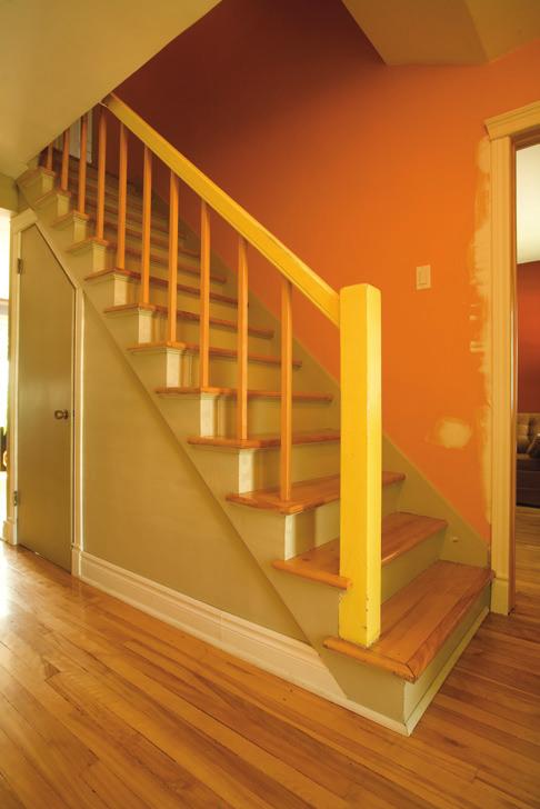
6 After Before 4
7 Stairway Terminology For those who are new to the world of stairparts, use the illustration below to familiarize yourself with the language of stairs and stairparts. Newel Post Handrail Stair Riser Square Top Baluster Stair Tread Stringer 5
8 6 Requirements Determine the components you require for your staircase Number of Components Required 1. Treads Equal to number of steps required 2. Risers Equal to the number of treads plus 1 3. Newel Posts 1 Newel Post placed at each end of handrail 1 Newel Post every handrail change in direction 1 Half Newel Post or Wall Mount Rosette when handrail finishes at wall 1 Newel Post to divide a long, horizontal section 4. Handrail Footage of handrail = Number of Treads + 1 (eg. For 13 Treads, 14 feet of handrail required) 5. Short balusters Stairway application: 1 baluster at front of each tread 6. Long balusters Stairway application:1 baluster at back of each tread Hallway application: 3 balusters per foot of handrail
9 Tools Hand Drill Hammer Putty Stick - to match color of stain Miter Box Saw Ratchet Wrench Level Tape Measure Sandpaper Handsaw Carpenter Glue Construction Adhesive Plumb Bob 7


10 Installation Stair Tread and Riser Installation Step 1 Cut riser to the proper width and height to fit onto the stringer. Step 2 Apply adhesive and fasten with finishing nails. Stringers Riser Step 3 Repeat steps 1 and 2 for all the remaining risers in the stair case. Step 4 Determine which, if any, of the ends of the treads will be overhanging the stringers. Riser Stair Tread Riser Stair Tread Stringers 1 1/2" overhang over side of stringer Open end Stair tread installation Bullnose required Closed end stair tread installation No Bullnose required Step 5 Determine the necessary width and length of the stair tread by using the following illustrations. Closed ended stair treads are cut flush with the stringer. 8
 Step 6 Cut stair tread to proper dimensions.")


11 Riser Stair Tread 1 1/2" overhang Cove Moulding Riser Riser 1 1/2" overhang Cove Moulding Side View Front View (Open end) Step 6 Cut stair tread to proper dimensions. Step 7 If installing an open end stair tread, attach a bullnose to each end of the stair tread that overhangs the stringer. Bullnose Cap Stair Tread Step 8 Attach stair tread using construction adhesive and 4 2-1/2 wood screws countersunk into the surface. Stringers Stair Tread Step 9 Apply adhesive to suitable size plugs, insert into the screw holes and sand smooth when dry. Step 10 Repeat process for all further stair treads requiring installation. Note In more advanced installations, the stair treads can be secured from underneath eliminating the need for plugs. 9
12 Newel Posts Installation Step 1 Construct a baluster line. Balusters and newel posts are all centered along the same baluster line. This is calculated by determining the exact location of all the balusters on the stair tread. The edge of each baluster should be 1.5 from the front edge of the stair tread. The center point of the balusters can be determined by calculating the width of the baluster, dividing by 2, and adding 1.5. For example the center point of a 1.5 baluster would be 2.25 from the edge of the stair tread (1.5 baluster/2 = edge room = 2.25 ). The center points of the newel posts lie along the same baluster line. WALL Landing TOP VIEW Newel Post To Upper Floor Stair Tread Baluster Stair Tread Leading Edges Down to floor Distance of baluster center point = 1 1/2" + (baluster width/2) 1 1/2" Edge of Baluster Stair Tread Bullnose Edge of wall or skirtobard 10

 Handrail Riser Long baluster: placed evenly between two adjacent short balusters Short baluster: front edge even with riser of lower step 4 1/2\" 4 1/2\" 1\" Riser Newel Post Check local Building")
13 Step 2 Determine the length between the starting newel Post and the landing newel Posts. The height of the handrail measured from the leading edge of every tread must meet the local building code. Account for 1 above the handrail on the top square block of the newel Post. Step 3 Cut newel Posts to appropriate size. Step 4 Install the starting newel Post, landing newel Post, and/or half-newel Posts with Newel Post Mounting Kit A (p. 22) or Newel Post Mounting Plate E (p. 24) Handrail Riser Long baluster: placed evenly between two adjacent short balusters Short baluster: front edge even with riser of lower step 4 1/2" 4 1/2" 1" Riser Newel Post Check local Building Codes Note 1 A Modern Style staircase installation does not require newel posts. 2 For hallway installations, an extra newel post is recommended to be installed for long sections. 11


14 Handrail Installation Stairway Hallway Hardwood 2 finishing nails 2" Softwood 2 screws 2 1/2" Hardwood Hardwood Softwood 2 screws 2 1/2" With shoerail Without shoerail Canada building code requirements Stairway Handrail Handrails cannot exceed 38 from front edge of each tread to top of handrail. Hallway Handrail Handrail required on landings shall not exceed 42 in height. 12

15 Stairway Installation Step 1 Lay a section of the handrail across the tread nosing and secure with a clamp. Step 2 Mark the handrail cuts where the newel and handrail intersect. Step 3 Make the appropriate cut ensuring the handrail is at the correct angle and length. Step 4 Dry fit the handrail to ensure a proper fit. Step 5 Install handrail at the appropriate height with Handrail Bolt Connector D (p. 23) on each side. Hallway Installation Step 1 Measure distance between newel posts and cut handrail to the proper length. Step 2 Dry fit the handrail to ensure a proper fit. Step 3 Install handrail at the appropriate height with a Handrail Bolt connector D (p. 23) on each side. Tips Mark and cut here To make a proper angled cut 1 Cut handrail to about ¼ oversize to make sure angles are correct. 2 Make a final precision cut to finished size. It is better to cut the handrail initially too long then too short. 13
16 Baluster Installation 14 Note Balusters can be attached to floor using any of 3 methods: 1 Dowel pin: A ¾ x 1 deep hole is drilled in each baluster location and baluster is inserted into hole. 2 Shoerail: The dowel pin is cut off. 3 Baluster Mounting Kit (B): The dowel pin is cut off. The maximum space between the center of balusters cannot exceed 4 A) Square Top Baluster Installation Stairway Installation Step 1 Balusters are installed so the distance between each does not exceed 4 center to center. There are typically two balusters per tread. A long baluster is used for the back of each tread and a short baluster is used for the front of each tread. Step 2 Mark the location of the centre of each baluster on the stair treads. Refer to Newel Post Installation section for details on constructing a baluster line. Step 3 If using dowel pin to secure baluster to the tread, drill a ¾ by 1 deep hole for each baluster center. Step 4 Cut each baluster top to proper height and angle.

17 Note Do not forget to add the depth of the groove on the handrail. Step 5 Install the balusters beginning at the bottom of the stairway. Insert each baluster into the dowel hole or shoerail and the top into the plow of the handrail. Use a level to ensure they are plum. For flat bottom baluster installation, use Baluster Mounting Kit (B) (p. 22). Step 6 Pre-drill and attach baluster into the plow under the handrail with appropriate finishing nails. Step 7 Cut the handrail fillets to fit in between the tops of each baluster. Step 8 Affix fillets using construction adhesive and finishing nails. Hallway Installation Step 1 The maximum spacing between centers of balusters is 4. In order for the balusters to be evenly spaced, the following formulas are used to determine the number of balusters required and the distance between each baluster. D = Distance between newel posts or walls # of balusters = (D/4) rounded up Distance between balusters = D/# of balusters Ex. If D = 50 # of balusters = (50/4) = 12.5 = 13 Distance between balusters = 50 /13 =


18 Step 2 Mark centre point of each baluster using the calculated Distance between balusters. Fillet Balusters Step 3 If using dowel pin to secure baluster to floor, drill a ¾ by 1 deep hole for each baluster centre. Shoerail Fillet Shoerail Step 4 Cut the top of each baluster to proper height. Note: Do not forget to add the depth of the groove on the handrail. Step 5 Insert each baluster into the dowel hole or shoerail and the top into the plow of the handrail. Use a level to ensure they are plum. Step 6 Pre-drill and attach baluster into the plow under the handrail with appropriate finishing nails. Step 7 Cut the handrail fillets to fit in between the tops of each baluster. Step 8 Affix balusters and fillets using construction adhesive and finishing nails. 16

19 B) Wrought Iron Installation Step 1 Balusters are installed so the distance between each does not exceed 4. There are typically two balusters per tread. A long baluster is used for the back of each tread and a short baluster is used for the front of each tread. Step 2 Mark the location of the centre of each baluster on the stair treads. Refer to Newel Post Installation section for details on constructing a baluster line. Step 3 Beginning at the bottom of the staircase, install the balusters by affixing them to the handrail and treads with the screws provided in the wrought iron package, using a level to ensure they are plum. Note Wrought iron balusters are sold in styles for either Stairway or Hallway installations. Stairway balusters have an angled top and hallway balusters have a flat top for ease of installation. Wrought iron illustration Panel baluster illustration 17
20 C) Modern Style Installation The modern railing system requires 2 short and one long baluster be installed on the first tread. Stairway Installation Step 1 Mark the location of the centre of the first short baluster ½ from the front of the riser and ½ from the edge of the false stringer. Step 2 Mark the location of the centre of the second short baluster 2-1/8 to the side of the first center point. Step 3 Using the same measurements as in step 1, mark the location of the center point of the short balusters on each tread for all remaining treads. Step 4 To determine the location of the center point of the long baluster, calculate the horizontal distance between the center points of the 2 short balusters (as determined in steps 1 & 3), and divide by 2. Mark the location of the center point of the long balusters on each tread for all remaining treads. Step 5 If using dowel pin to secure baluster to the tread, drill a ¾ by 1 deep hole for each baluster centre. Step 6 Mark the location of the center point of the first baluster on the landing. 18 Note Landing or Hallway balusters are all long, ensuring it is ½ from the front of the top riser and aligns with the midpoint between the 2 short balusters on the first tread (calculated in steps 1 and 2).

21 Step 7 Dry fit the first 2 short balusters on the first tread and the one long baluster on the landing and ensure they are plum. Step 8 Lay handrail on the treads between 2 short balusters and against the top long baluster. Cut the handrail at the appropriate angle and length. Step 9 Permanently affix all of the stairway balusters, ensuring they are plum. Step 10 Using glue and screws, affix the handrail to the balusters ensuring that the top of the handrail is a minimum of 2 above the top of the balusters. Step 11 Butt the handrail to the face of the long baluster on the landing, ensuring that the top of the handrail is flush with the bevil of the baluster. Step 12 Screw the handrail to the baluster as shown (p.20 Fig.A). Hallway Installation Step 1 Mark centre point of each baluster using the calculated Distance between balusters. Step 2 If using dowel pin to secure baluster to floor, drill a ¾ by 1 deep hole for each baluster centre. Step 3 Measure and cut the handrail to the appropriate length. 19


22 Step 4 The last baluster must be affixed to the wall using glue and a screw by drilling a hole through the baluster into the wall at a height of between from the floor. Step 5 Install the remainder of the balusters with glue and ensure they are plum. Step 6 Using glue and screws, affix the handrail to the balusters ensuring that the top of the handrail is a minimum of 2 above the top of the balusters. Fig. A Fig. B 28" Finishing Tips Dry fit all components before adhering. Pay special attention to measuring and cutting components to proper size. Countersink finishing nails and putty nail head holes. Sand the surface before finishing. Allow adhesive to cure for 24 hrs. Use your favorite stain or varnish to protect and embellish your staircase. 20


23 Accessories Wall Mount Rosette Wall Mount Rosette Wall Mount Rosette Decorative addition for handrail ending at a wall as well for the handrail bracket. Handrail Handrail Bracket Handrail Used when installing a handrail to a wall. Stair Tread Bullnose Cap Stair Tread Used to finish off an end of a stair tread that is visible. Stair Tread Bullnose Cap 21

24 Installation Hardware A) Newel Post Mounting Kit Used to Safely and Firmly Connect Newel Posts to Your Floor Surfaces. B) Baluster Mounting Kit Connects Balusters to Floors and Stairs. 22


25 C) Handrail & Newel Post Connector Connects: Handrail to Newel Post Newel Post to Stair Riser D) Handrail Bolt Connector Connects: Handrail to Newel Post Handrail to Wall Handrail to Handrail 23


26 E) Newel Post Mounting Plate Securely Fastens Newel Post to Floor. 24


27 Visual Glossary The detailed glossary below illustrates examples of the different parts that make up a staircase as well as their individual function. For a complete parts listing, call your local home improvement retailer. Handrail Handrail Handrail with Fillet Used when wood balusters are to be inserted into the plow. Fillet Plow Handrail Handrail without Fillet Used for wall mounted applications or with wrought iron balusters. Handrail Balusters Modern Handrail Handrail attaches to side of balusters rather than on top of them. Modern Handrail Fillet Balusters Fillet Shoerail A strip running along the floor for insertion of balusters. Shoerail Shoerail Note: Please check with your local building codes before starting any installation. 25
28 Newel Posts Newel Post Used at beginning and end of handrail and every time handrails changes direction. Half Newel Post Used when handrail ends at a wall. 26
29 Balusters Square Top Baluster Used for both stairway and hallway installations. Fits into handrail with fillet and shoerail. Modern Baluster Used for both stairway and hallway installations. Baluster is affixed to the side of the modern handrail. 27
30 Stairway Hallway Wrought Iron Balusters Used with handrails without fillet. Stairway Hallway Wrought Iron Panels Used with handrails without fillet. 28


31 Treads and Risers Tread Tread The horizontal boards that make up the steps of the staircase. Riser Riser The decorative vertical rise between treads that provides additional support. Others Stringer Stringer The angled boards that support the stair treads and risers. Stringer Stringer Skirtboard Skirtboard A decorative trim board used on either open or closed sides of the stair. 29
32 Urban Wrought Iron Balusters Installation Tools and Hardware Required Phillips screw driver Hand saw Level Masking tape Construction adhesive 8 screws per panel baluster Caulk Installation Guide Step 1 Balusters are installed so the distance between each does not exceed 4. There is typically one panel baluster per tread. Step 2 Mark the location of the center of each panel baluster on the stair treads. Refer to Newel Post Installation section for details on constructing a baluster line. Step 3 Before installing panel baluster, ensure the removable cap is on the post. See *TIPS AND TRICKS. Step 4 Beginning at the bottom of the staircase, install the panel balusters by affixing them to the treads first with the screws provided. 30
 to the underside of the handrail with the screws provided.")
.")
33 Step 5 Affix the top plate on the short side (attached cap) to the underside of the handrail with the screws provided. Step 6 Affix the top plate on the long side (removable cap) to the underside of the handrail with the screws provided. Note Slight handrail angle variation is addressed by the removable cap. The removable cap may be moved up slightly to reach the underside of the handrail however at least half of the length of the cap must remain on the post (overlap). Tips and Tricks To prevent potentially rattling of the panel baluster, apply caulk inside the removable cap where it overlaps the post. Remove any excess caulk and allow it to dry properly. 31
34 Aluminum Newel Post Installation Product Installation Features Two top newel extensions are provided to accommodate both stairway and hallway installation heights. Top swiveling mounting plate allows for ease of installation on both staircase and hallway applications accommodating virtually any handrail angles. Top swiveling mounting plate incorporates angled countersunk screw holes for easy tool access. Thick metal anchoring brackets for reliable installation Note The following instructions are for a typical staircase with a 9 run, 7.1/2 rise and 1.1/2 nosing (measured from the front edge of the tread to the face of the riser). Any other variations need to meet local building code. It is important to ensure there is proper structural support under the newel post and /or any location where the handrail is attached to a wall. 32
35 Step 1 Locate Starting Newel Post Position To determine the exact location of the starting newel post on the starting tread, the center of the newel should be 3.3/16 from the nosing edge of the starting tread and 3.3/16 from the side of the starting tread. Mark the center position of the newel on the starting tread. Draw two extended lines parallel to the front and the side of the starting tread intersecting at the point that marks the center position identified above. 3.3/16 3.3/16 Line up the centering lines on the anchor bracket with the extended lines drawn above. Drill an appropriate pilot hole into the tread and the structural support beneath for each screw hole on the anchor bracket. Use fasteners appropriate for your application. (fasteners not included). Fasten newel post to the starting tread. Make sure that the longer newel extension is used for the starting newel and the shorter extension for the landing newel. 33
36 Step 2 Locate Landing Newel Post Position To determine the exact location of the landing newel post on the landing, the center of the newel should be 3.3/16 from the nosing edge of the landing and lined up with the starting newel post. Mark the center position of the newel on the landing. (Note: The line between the center of the starting newel and the center of the landing newel forms the baluster line.) Draw one extended line parallel to the front of the nosing edge of the landing and one extended line along the baluster line that intersects at the point that marks the center position identified above. 3.3/16 3.3/16 Line up the centering lines on the anchor bracket with the extended lines drawn above. Drill an appropriate pilot hole into the tread and the structural support beneath for each screw hole on the anchor bracket. Use fasteners appropriate for your applications (fasteners not included). 34 Fasten newel post to the landing.
37 Make sure that the longer newel extension is used for the starting newel and the shorter extension for the landing newel. Step 3 Install Handrail It is strongly advised to use a scrap piece of wood (e.g. 2 x4 lumber) in place of the actual handrail to determine the angle setup of the miter saw for cutting the stairway handrail. See instructions below: Lay a section of 2 x4 lumber across the tread nosing (make sure the 2 x4 is long enough to touch at least 3 tread nosings on the staircase) and secure with a clamp to the top newel post. Identify this piece as stairway. Lay a section of 2 x4 lumber on the landing next to the 2 x4 on the staircase. Identify this piece as hallway. (Make sure the two pieces of 2 x4 overlap each other). Hallway 2 x4 Stairway 2 x4 35
38 Mark a line where the top of both 2 x4 s meet. Mark another line where the bottom of both 2 x4 s meet. Draw a straight line on each 2 x4 between the top and the bottom marks. Point where handrails meet on the top Point where handrails meet on the bottom Stairway 2 x4 Hallway 2 x4 Stairway 2 x4 Hallway 2 x4 Use these two pieces of 2 x4 as the template to determine the miter saw angle. Once the angle is determined, you can now cut the ends where your stairway and hallway 2 x4 s join. Dry fit the 2 x4 s together to ensure proper alignment. A slight adjustment to the angle of the saw may be required if the initial dry fit test does not give an acceptable alignment. If the joint alignment is satisfactory, trim the ends of the actual handrails to suit your application and securely fasten the hallway and stairway handrails together. 36 Handrail fasteners not included.
39 Adjustable Aluminum Baluster Installation Balusters are installed so the distance between each does not exceed 4. There are typically two balusters per tread. A long baluster is used for the back of each tread and a short baluster is used for the front of each tread. Due to the fact that our balusters are adjustable in height, the same baluster type can be used for both the back and the front of each tread. Product Installation Features Thanks to the patent pending unique bottom swivel design of our Adjustable Aluminum Baluster, this baluster can be used on both flat tread and/or angled stringer installation. Top swiveling mounting plate allows for ease of installation on both staircase and hallway applications accommodating virtually any handrail angles. Top swiveling mounting plate incorporates angled countersunk holes for easy tool access. Patented height-adjustability design fits virtually any handrail height. 37
40 Each baluster comes with two bottom swivel caps. One specifically designed for flat tread installation and the other for angled stringer installation. Flat tread Angled Stringer Note The following instructions are for a typical staircase with a 9 run, 7.1/2 rise and 1.1/2 nosing (measured from the front edge of the tread to the face of the riser). Any other variations need to meet local building code. It is important to ensure there is proper structural support under the newel post and /or any location where the handrail is attached to a wall. Step 1 Locate the Baluster Position (assuming newel posts and the handrails are previously installed) Construct a baluster line by drawing a line on each tread through the center of both newel posts. Balusters and newel posts are all centered along the same baluster line. 38
41 4. Newel Post Newel Post To determine the exact location of the balusters on the stair tread, the center of each front baluster should be one half the width of the baluster from the nosing edge of the stair tread (this would exclude the starting tread if the newel is installed on it). Mark the center position of each front baluster. Front Baluster Center 1.13/16 The center of each back baluster should be positioned 4.5 from the center of the front baluster. Mark the center position of each back baluster. Back Baluster Center 1/2 Front Baluster Center Front Baluster Center 39
42 Step 2 Fastening the Bottom of the Baluster to Tread Remove the bottom swivel cap with offset cut-out (only used for stringer installation). Keep the bottom swivel cap with the center cut-out on the bottom tube. Make sure the bottom tube stays inserted in the top tube. Make sure the screw holes on the bottom swivel are in line with the baluster line. Line up the center of the baluster tube with the center marks identified in Step 1. Mark the position of the swivel holes. Drill an appropriate pilot hole for each swivel holes. Fasten the baluster into the tread using the screws provided. To prevent the bottom swivel cover from moving, it is recommended that a small amount of clear silicon be applied between the tread and the bottom of the cover. Step 3 Fastening the top of the Baluster to the Handrail Extend the top tube until the swivel rests against the underside of the handrail. Using a level, make sure that the baluster is leveled in both directions. Tighten the set screw to lock the height of the baluster. 40
43 Allen Key Set Screw Mark the position of the swivel holes on the underside of the handrail. Drill an appropriate pilot hole for each swivel hole. ( Note: Swivel holes are countersunk and at an angle to facilitate easy access of a power tool.) Fasten the baluster to the handrail. Repeat Step 2 and 3 until all the balusters are installed. Hybrid Baluster Kit Installation Balusters are installed so the distance between each does not exceed 4. There are typically two balusters per tread. A long baluster is used for the back of each tread and a short balus- ter is used for the front of each tread. The design of this kit allows for virtu- ally any height of baluster due to the fact that the wood component can be cut to the required height. The same Hybrid Baluster Kit can be used for both the back and the front of each tread. This patent pending product provides multiple design possibilities. You may select your preferred wood species and finish to your own taste prior to assembly. 41
44 Product Installation Features Thanks to the patent pending unique bottom swivel design of our Hybrid Baluster Kit, this kit can be used on both flat tread and/or angled stringer installation. Top swiveling mounting plate allows for ease of installation on both staircase and hallway applications, accommodating virtually any handrail angles. Top swiveling mounting plate incorporates angled countersunk holes for easy tool access. Each kit comes with two bottom swivel caps. One specifically designed for flat tread installation and the other for angled stringer installation. Flat tread Angled Stringer 42
45 Note The following instructions are for a typical staircase with a 9 run, 7.1/2 rise and 1.1/2 nosing (measured from the front edge of the tread to the face of the riser). Any other variations need to meet local building code. It is important to ensure there is proper structural support under the newel post and /or any location where the handrail is attached to a wall. Step 1 Kit Assembly ( assuming newel posts are previously installed) For each baluster, determine the required height of the wood component (please take into account the recess in the metal caps that cover the wood component). Cut the wood to length making sure that the ends of the wood are cut square. Remove the cardboard piece from the kit assembly. Place the metal caps over the wood component. Mark the screw hole and drill appropriate pilot hole as straight as possible into the wood (min. 1.1/4 deep). (drill min. 1.1/4 deep) Metal Cap Mark Screw Hole Wood Component 43
46 Unscrew both swivels from the extensions of the kit (top and bottom). For both the top and bottom components of the kit, drop the provided wood screw through the extension making sure the screw comes out of the bottom. Attach the metal cap to the extension. Insert the wood component into the cap and fasten the screw into the wood component. It is recommended to use a power drill with an extended bit. Extension Metal Cap Wood Component Reassemble the top swivel. Prior to reassembling the bottom swivel, ensure the proper bottom swivel cover is chosen for either stringer application or tread application. Flat tread Angled Stringer 44 For tread application, slide the bottom swivel cap with the center cut-out on the bottom extension.
47 For stringer application, slide the bottom swivel cap with offset cut-out on the bottom extension. Reassemble the bottom swivel. Step 2 Locate the Baluster Position ( assuming newel posts and handrail are previously installed) Construct a baluster line by drawing a line on each tread through the center of both newel posts. Balusters and newel posts are all centered along the same baluster line. Newel Post Newel Post To determine the exact location of the balusters on the stair tread, the center of each front baluster should be one half the width of the baluster from the nosing edge of the stair tread (this would exclude the starting tread if the newel is installed on it). Mark the center position of each front baluster. Front Baluster Center 2.1/8 45
48 4. The center of each back baluster should be positioned 4.5 from the center of the front baluster. Mark the center position of each back baluster. Back Baluster Center 1/2 Front Baluster Center Front Baluster Center Step 3 Fastening the Bottom of the Baluster to Tread ( assuming newel posts and handrail are previously installed) Make sure the screw holes on the bottom swivel are in line with the baluster line. Line up the center of the baluster tube with the center marks identified in Step 2. Mark the position of the swivel holes. Drill an appropriate pilot hole for each swivel holes. Fasten the baluster into the tread using the screws provided. To prevent the bottom swivel cover from moving, it is recommended that a small amount of clear silicon be applied between the tread and the bottom of the cover. Handrail fasteners not included. 46
49 Step 4 Fastening the Top of the Baluster to the Handrail Rest the top swivel against the underside of the handrail. Using a level, make sure that the baluster is leveled in both directions. Mark the position of the swivel holes on the underside of the handrail. Drill an appropriate pilot hole for each swivel hole. Fasten the baluster to the handrail. (Note: Swivel holes are countersunk and at an angle to facilitate easy access of a power tool.) Repeat Step 3 and 4 until all the balusters are installed. 47

50 Enhance Your Stairway
A Step-by-Step How To Guide
 HOW TO REMODEL YOUR STAIR A Step-by-Step How To Guide Add new life to your staircase and achieve professional results. 1 Renovating your staircase is more than a remodel, it s a transformation of your
Wood. collections. Hampton. Carolina. Colonial. Craftsman Box Newels
 Wood s Carolina Hampton Craftsman Box Newels Colonial 32 Wood species Hemlock Maple Red Oak Poplar Primed Alder Beech Birch Cherry Brazilian Cherry Hickory Mahogany White Oak Yellow Pine Walnut Additional
SUREWOOD ~ LNL. How to build a staircase like a pro. Post-To-Post Staircase System. Identify Your Type of Post-to-Post Staircase: Landing Newel Post
 How to build a staircase like a pro. 1 Identify Your Type of Post-to-Post Staircase: Post-To-Post Staircase System Post Post SUREWOOD ~ LNL Rake Wall Rail Level Run Open Staircase with Square Top alusters
SUREWOOD ~ LNL. How to build a staircase like a pro. Post-To-Post Staircase System. Identify Your Type of Post-to-Post Staircase: Landing Newel Post
 How to build a staircase like a pro. 1 Identify Your Type of Post-to-Post Staircase: Post-To-Post Staircase System Post Post SUREWOOD ~ LNL Wall Rail Square Top alusters Shoe rail Open Staircase with Square
Chapter 17 - Porch Trim
 Chapter 17 - Porch Trim Contents Chapter 17 - Porch Trim... 17-1 Timing & Prerequisites... 17-2 Trim on Porch Beams (Volunteer)... 17-4 Smart Trim on the Bottom of the Beam... 17-4 Smart Trim on the Inside
ATLANTIS RAIL Contact Information
 ATLANTIS RAIL Contact Information Customer Service (800) 541-6829 (508) 732-9191 Spectrum System Installation Instructions Atlantis Rail s Spectrum System is an easy to install, universal cable railing
BRACKET FIX SYSTEM FITTING INSTRUCTIONS
 Whether building a new staircase or replacing old banisters, the patented Bracket Fix stair balustrading system will enable you to complete the work quickly and easily. The Richard Burbidge patented Bracket
AXXYS Stairparts Fitting Instructions
 These Fitting Instructions are for use with the AXXYS range with metal balusters within B&Q These instructions are not for use with any other ranges outside the AXXYS range. If you are using our glass
Salter Industries Spiral Stair
 Salter Industries Spiral Stair The Leader in Spiral Staircases Continuous Sleeve Stair Installation Instructions TOOLS NEEDED: 1. Electric drill with hex chuck and Phillips bit 2. Drill bits 1/8", 1/4",
TREX ENHANCE RAILING (Also Applies to Trex Select Railing) Installation Instructions
 Installation Instructions") TREX ENHANCE RAILING (Also Applies to Trex Select Railing) NOTE: All Enhance Railing lengths are manufactured at CLEAR SPAN dimensions (spanning between space of posts): 7" for 6' clear span. Note that
TREX ENHANCE RAILING (Also Applies to Trex Select Railing) NOTE: All Enhance Railing lengths are manufactured at CLEAR SPAN dimensions (spanning between space of posts): 7" for 6' clear span. Note that
CXT PRO RAILING INSTALLATION INSTRUCTIONS For Installations Using Aluminum and Glass Balusters Sold Separately
 CXT PRO RAILING INSTALLATION INSTRUCTIONS For Installations Using Aluminum and Glass Balusters Sold Separately CCRR-0171 PFS AA-652 Drill/power screwdriver Assorted drill bits Hammer Miter or circular
Get Creative. Product Info Ideas Videos Guidelines. Rail Fastening Innovations. Balcony Connect level hand rail to newel
 Get Creative www.creativestairparts.com Check back FREQUENTLY for new ideas, tips, and innovations Product Info Ideas Videos Guidelines Rake Connect hand rail to newel Details on Page 54 Rail Fastening
TREX SELECT RAILING Installation Instructions
 RAILING NOTE : All Trex Select Railing lengths are manufactured at ON CENTER dimensions (spanning from center of each post): 67-5/8" (76.8 cm) for 6' (.83 m) on center, and 9-5/8" (35.3 cm) for 8' (.44
TREX SELECT RAILING. Installation Instructions PARTS
 RAILING NOTE : All Trex Select Railing lengths are manufactured at ON CENTER dimensions (spanning from center of each post): 67-5/8" (76.8 cm) for 6' (.83 m) on center, and 9-5/8" (35.3 cm) for 8' (.44
Installation Instructions for. Before You Begin TOOLS REQUIRED
 Composite Railing System STEP-BY-STEP Installation Instructions for Spectrum Composite Railing Virtually maintenance free 20-year warranty EverNew Spectrum Railing system is designed to work with a number
installation care & maintenance instructions lifecycledecking.com 25-year limited residential warranty 20-year limited commercial warranty
 installation care & maintenance instructions lifecycledecking.com 25-year limited residential warranty 20-year limited commercial warranty Installation Instructions As with any building project, use proper
Installation Instructions for. Handrail Component System
 Handrail STEP-BY-STEP Installation Instructions for Handrail Component System Rise in Inches Run in Inches 8 8.5 9 9.5 10 10.5 11 11.5 12 12.5 13 13.5 14 14.5 15 8.5 47 45 43 42 40 39 38 36 35 34 33 32
The following instructions will guide you through the installation of your new vinyl railing.
 Installation Guide St. James Vinyl T-Rail Tools Required Protective eye glasses 3/8 x 3 Concrete Anchors/Fasteners (for Tape measure concrete installations) Variable speed drill/screwdriver Philips Driver
Balustrade Systems / Installation Instructions
 A. PARTS AND SUPPLIES NEEDED FOR INSTALLATION Hardware included for each 10 section of rail: 2 3 x 1-1/2 L-brackets 4 1-3/4 x 3/16 Blue hex-head screws for anchoring the L-brackets to the newel cap, column
INSTALLATION SUGGESTIONS LEVEL APPLICATION LIMITED WARRANTY
 INSTALLATION SUGGESTIONS LEVEL APPLICATION LIMITED WARRANTY L.J. Smith, Inc. issues the following Limited Warranty: The product(s) furnished hereunder are warranted to be free from defects in material
T A P N T W I S T INSTALLATION GUIDE
 T A P N T W I S T a dynamite way to install balusters INSTALLATION GUIDE T A P N T W I S T a dynamite way to install balusters Your Beautiful New Staircase is Just Steps Away! Tools You Need: Tape Measure
KNEEWALL APPLICATION
 INSTALLATION SUGGESTIONS KNEEWALL APPLICATION LIMITED WARRANTY L.J. Smith, Inc. issues the following Limited Warranty: The product(s) furnished hereunder are warranted to be free from defects in material
Build Outdoor Stairs. Stair Building Terms There are five basic design elements you'll need to consider when planning outdoor stairs:
 Build Outdoor Stairs Stair Building Terms There are five basic design elements you'll need to consider when planning outdoor stairs: The Total Run (Fig. 1) is the total horizontal distance covered by the
STAIRSERVICE.COM. Stair system design and selection catalog. A step ahead, a step above 1 (800) Fax (408)
 Fax (408)") STAIRSERVICE.COM A step ahead, a step above Stair system design and selection catalog. 1 (800) 940-1057 1545 Berger Drive San Jose, CA 95112 Fax (408) 920-0109 Sales@stairservice.com Step by step Design
STAIRSERVICE.COM A step ahead, a step above Stair system design and selection catalog. 1 (800) 940-1057 1545 Berger Drive San Jose, CA 95112 Fax (408) 920-0109 Sales@stairservice.com Step by step Design
LJ ⅝ (270 mm) LJ All above are 1 x 10½ or 11½ (25 mm x 267 mm or 292 mm)
 LJ All above are 1 x 10½ or 11½ (25 mm x 267 mm or 292 mm)") Starting Steps for use with Box Newels Our LJ-8030 and LJ-8050 steps are for use with any of our Box Newels. LJ-8030 Single Bullnose Starting Step LJ-8050 Double Bullnose Starting Step WALL LJ-8030 8⅞
Starting Steps for use with Box Newels Our LJ-8030 and LJ-8050 steps are for use with any of our Box Newels. LJ-8030 Single Bullnose Starting Step LJ-8050 Double Bullnose Starting Step WALL LJ-8030 8⅞
COMPOSITE RAILING INSTALLATION
 COMPOSITE RAILING INSTALLATION Tools All you ll need is a hammer and screw gun, circular saw (carbidetipped blade with fewer than 20 teeth is recommended), level, tape measure, rasp and blue chalk line.
Figure 1. RAILING INSTALLATION The following instructions describe the installation of three types of railing sections: Line, Stair, and Angled
 Veranda Railing System Veranda railing systems are designed to work with a number of different decking materials and surfaces. Before initiating any project, obtain a copy of your local building codes
Straight Stringer Installation Instructions
 Straight Stringer Installation Instructions Floor-to-Wall Installation F L I G H T P L A N Unpack: What s included? Your Stringer Tread Screws (8) per tread (1) Torque Wrench (1) Socket (for the brackets
Installing AZEK Evolutions Rail
 Installing Evolutions Rail TM Contemporary Installing AZEK Evolutions Rail Installing Evolutions Rail Contemporary Style... 2 Installing CableRail by Feeney for Evolutions Rail Contemporary Style... 8
PRODUCT GUIDE. 2nd Edition February
 PRODUCT GUIDE 2nd Edition February 2010 www.ki-lumber.com Post-To-Post 34-38 Rail Height 42 Balcony Rail Height 1-1/4 Baluster s To Use For Proper Rail Height 1 st Baluster on the Tread.36 2 nd Baluster
TREX TRANSCEND RAILING
 RAILING NOTES:» RAILINGS ARE DESIGNED TO BE INSTALLED OVER THE DECKING FRAME OR ON INSIDE OF RIM JOIST. NOTCHING OF PRESSURE-TREATED POSTS OR POSTS INSTALLED ON OUTSIDE OF RIM JOIST IS NOT ALLOWED.» All
The following instructions will guide you through the installation of your new vinyl railing stair kit.
 Installation Guide Vinyl Standard Stair Railing Tools Required Protective eye glasses Tape measure Variable speed drill/screwdriver Rotary hammer or hammer drill and masonry percussion bit recommended
INSTALLATION INSTRUCTIONS. Level Rail With Cap: Page 2 Level Rail Without Cap: Page 8 Stair Rail: Page 12
 INSTALLATION INSTRUCTIONS Level Rail With Cap: Page 2 Level Rail Without Cap: Page 8 Stair Rail: Page 12 LEVEL RAIL WITH CAP The testing was performed in accordance with procedures and methods referenced
installation care & maintenance instructions moistureshield.com limited lifetime warranty
 installation care & maintenance instructions 866.729.2378 moistureshield.com limited lifetime warranty It s comforting to know that you re about to build a deck that gives you every possible advantage.
CONTENTS TOOL LIST U P S I D E I N N O V A T I O N S, L L C RAMP AND STEP SYSTEM ASSEMBLY INSTRUCTIONS. Revised: June 2013
 U P S I D E I N N O V A T I O N S, L L C RAMP AND STEP SYSTEM ASSEMBLY INSTRUCTIONS TOOL LIST Required Tools: - Reciprocating Saw with Metal Cutting Blade - Drill - 7/16 Drill Bit for Metal Drilling -
Aluminum Clad Wood Window 1/2 Reinforced Field Mulling and Stacking Supplement
 Aluminum Clad Wood Window 1/2 Reinforced Field Mulling and Stacking Supplement 1 Aluminum Clad Wood Window 1/2 Reinforced Field Mulling and Stacking Supplement The following instructions are a supplement
HANDRAIL HEIGHT PER LOCAL CODE AUTHORITY
 WITH OPTIONAL S.S. S PLEASE READ PLEASE READ THESE INSTRUCTIONS THOROUGHLY PRIOR TO BEGINNING THE INSTALLATION! THIS INSTRUCTION SHEET IS INTENDED TO PROVIDE A SPECIFIC GUIDE TO FOLLOW FOR THE INSTALLATION
STAIR TREAD & RISER INSTALLATION GUIDELINES
 STAIR TREAD & RISER INSTALLATION GUIDELINES ARTISTIC FINISHES DOES NOT WARRANTY THE COMPLETENESS OR ACCURACY OF ANY INSTALLATION. THE INSTALLATION CONTRACTER MUST HAVE THE EXPERIENCE AND KNOWLEDGE TO COMPLETE
AFCO-Rail Post INSTALLATION INSTRUCTIONS AFCO-RAIL POST
 AFCO-Rail Post INSTALLATION INSTRUCTIONS TOOLS REQUIRED: Drill Bits (for the appropriate fastener) Drill (with adjustable clutch, recommended) Level String Line Tape Measure Tools to install fasteners
Get Creative. Table of Contents. Product Info Ideas Videos Guidelines. Table of Contents
 Get Creative www.creativestairparts.com Check back FREQUENTLY for new ideas, tips, and innovations Table of Contents Table of Contents Product Info Ideas Videos Guidelines Introducing the Gallery App on
INSTALLATION GUIDE. 5" Balustrade System
 5" Balustrade System PARTS LIST ITEM QTY A PORCH POST INSTALLATION KIT (PPK6) (SEE STEP 3C) 5 1/2" x 5 1/2" Trim Collar 2 2" Wide x 1 1/2" x 2" Angle Bracket 4 MATERIALS NEEDED INSTALLATION GUIDE #14 x
Balustrade System Installation - Cambridge & Huntington
 A. PARTS AND SUPPLIES NEEDED FOR INSTALLATION Hardware included for each 10 section of rail: 2 3 x 1-1/2 L-brackets 4 1-3/4 x 3/16 Blue hex-head screws for anchoring the L-brackets to the newel cap, column
RAILING R A IL ING 51
 RAILING RAILING 5 TREX TRANSCEND RAILING NOTES:» TREX TRANSCEND RAILINGS ARE DESIGNED TO BE INSTALLED OVER THE DECKING FRAME OR ON INSIDE OF RIM JOIST. NOTCHING OF PRESSURE-TREATED POSTS OR POSTS INSTALLED
Tape Measure Carpenter s Square Touch-up Paint Chalk Line. Blue 242. Template
 ATLANTIS RAIL Contact Information: Atlantis Rail Systems 70 Armstrong Rd. Plymouth, MA 02360 (800) 541-6829 or (508) 732-9191 (508) 732-9798 www.atlantisrail.com NOVA System Installation Instructions The
PARTS INCLUDED IN FIXED STAIR CABLE RAIL KIT:
 175 SERIES FIXED STAIR CABLE RAIL - INSTALLATION INSTRUCTIONS PARTS INCLUDED IN FIXED STAIR CABLE RAIL KIT: FIXED STAIR TOP RAIL (1) A FIXED STAIR BOTTOM RAIL (1) B D UPPER SADDLE BRACKET (1) C BRACKET
Vivian Mansion Assembly Instruction By Laser Dollhouse Designs
 Vivian Mansion Assembly Instruction By Laser Dollhouse Designs NOTE 1: Please do a dry assembly using only tape to hold house together. This will get you familiar with parts, location, and fit. This also
PVC Composite Railing & Stair Kit
 FREEDOM-WEB PVC Composite Railing & Stair Kit INSTALLATION INSTRUCTIONS Read all instructions prior to installing product. Refer to manufacturers safety instructions when operating any tools. To register
Fortress Fe Posts must always be secured to the deck framing. Fortress Fe Posts should never be attached to only the deck boards.
 Installation Instructions for FortressCable H-Series Stair Panels with Simplified Stair Bracket SSB-05 and Fe Posts It is the responsibility of the installer to meet all code and safety requirements, and
Frameless Inline Door With Return QCI5263
 INSTALLATION INSTRUCTIONS Frameless Inline Door With Return QCI5263 WALL MOUNT HINGES FRAMELESS DOOR / PANEL / RETURN PANEL QCI5263 REV. 0 Page 1 Certified 06/17/2016 Parts List with wall mount hinges
BARCLAY SPIRAL STAIRCASE SPECIFICATIONS
 BARCLAY SPIRAL STAIRCASE Congratulations on your purchase of our Barclay 5' Spiral Staircase! Modeled on the structure of a staircase salvaged from a paper mill in the Ottawa Valley, the Barclay's decorative
Wallbeds Northwest ENDURA CABINET PLANS AND INSTRUCTIONS
 Thank you for purchasing your Wall Bed from Wallbeds Northwest. If you have purchased a complete "Endura DIY Kit," then much of the work is already done for you. Please skip to assembly instructions. Note
Installation of Balustrade Systems
 Installation of Balustrade Systems IMPORTANT: Be sure to mark the center point of each newel post's location prior to installation to insure proper spacing. All product interfaces must use PL Premium Adhesive
ATLANTIS RAIL Contact Information: Atlantis Rail Systems 70 Armstrong Road 3900 Civic Center Drive Plymouth, MA North Las Vegas, NV 89030
 ATLANTIS RAIL Contact Information: Atlantis Rail Systems 70 Armstrong Road 3900 Civic Center Drive Plymouth, MA 02360 North Las Vegas, NV 89030 (800) 541-6829 or (508) 732-9191 (508) 732-9798 www.atlantisrail.com
Stair Tread & Riser Installation Guide
 Stair Tread & Riser Installation Guide 1 P age Wood A Natural Product We, at Artistic Finishes, accept and appreciate the natural beauty that comes from real wood. Because no two trees produce the same
HOW TO INSTALL ELITE PANELED WAINSCOTING Using X-Rails with Either Raised, Flat or Beaded Panels
 HOW TO INSTALL ELITE PANELED WAINSCOTING Using X-Rails with Either Raised, Flat or Beaded Panels 1. First, remove the cover plates from all electrical outlets. All baseboards should also be removed; the
INSTALLATION INSTRUCTIONS GUIDE
 CERTAINTEED RAILING AND DECKING INSTALLATION INSTRUCTIONS GUIDE Kingston Vinyl Railing and Vinyl Decking CONTENTS Important Information Before You Begin...3 Helpful Hints, Tips, Fire Information and Tools
S T A I R B A L U S T R A D E E L E M E N T S P R E - D R I L L E D R A I L S Y S T E M
 S T A I R B A L U S T R A D E E L E M E N T S P R E - D R I L L E D R A I L S Y S T E M The following instructions are for installing Richard Burbidge Elements pre-drilled rail Stair Balustrading. If you
Woodline USA Woodline Spacer Fence System
 Woodline USA Woodline Spacer Fence System MADE IN THE USA Includes: (1) ¼ Spacer Fence (1) 3/8 Spacer Fence (1) ½ Spacer Fence (1) Hardware Package (1) 3 Piece Brass bar set (2) Setup Blocks Visit Us Online
Fortress Al HOME posts must always be secured to the deck framing. Fortress Al HOME posts should never be attached to only the deck boards.
 Installation Instructions for Fortress Al HOME Traditional Adjustable Panels with Simplified and Al HOME Posts It is the responsibility of the installer to meet all code and safety requirements, and to
PAINT & MISC. Notes. Table of Contents. Front Handrail Posts Front Handrails Closet Shelving Exterior Deck...
 118 PAINT & MISC. Table of Contents Front Handrail Posts... 119 Front Handrails... 122 Closet Shelving... 125 Exterior Deck... 127 Look for painter s tape on the hammer drill for where to set the depth.
Template. Blue 242. May 2018 trademarks of Suncor Stainless, Inc. Loctite is a registered trademark of Henkel Corporation
 ATLANTIS RAIL Contact Information: Atlantis Rail Systems 70 Armstrong Road 3900 Civic Center Drive Plymouth, MA 02360 North Las Vegas, NV 89030 (800) 541-6829 or (508) 732-9191 (508) 732-9798 www.atlantisrail.com
Frameless Fixed Panel Slider
 INSTALLATION INSTRUCTIONS Frameless Fixed Panel Slider QCI-5279 SINGLE ROLLER WITH ANTI-JUMP DOUBLE ROLLERS QCI5279 Rev Page Certified 08/09/6 Tools: To install your New Shower Enclosure, you may need
Installation Manual Using Existing Handrail Version 4.0 Oct 2017
 Installation Manual Using Existing Handrail Version 4.0 Oct 2017 ORDER OF ASSEMBLY TOOLS YOU WILL NEED - Fine Saw - Sander - Wood Filler - Allen keys - Screw Driver - Drill - Suitable Screws PROTECTING
Continuous Handrail Kit Installation Instructions
 Continuous Handrail Kit Installation Instructions ALUMINUM RAILING SYSTEM Canadian Version Wall Application (see page 2) Railing Application (see page 7) Wall anchors not provided Hardware included: 1x
DekPro Prestige Aluminum Rail System Level Railing Installation Instructions
 ing Installation Guide Please read all instructions completely before starting any installation of DekPro Prestige Railing Systems. SAFETY: Always be safe and follow all instructions when using power tools
TREX REVEAL RAILING Installation Instructions
 TREX REVEAL RAILING BRACKET HARDWARE STAIR APPLICATIONS (INCLUDING STAIR SWIVEL BRACKETS, STAIR CROSSOVER BRACKET, AND COMPOUND SWIVEL BRACKETS) FIXED BRACKET Stair HARDWARE AA. Bottom Stair Bracket and
Kentucky 4H Wood Science Plans Notebook. Plans Level 3
 Kentucky 4H Wood Science Plans Notebook Plans Level 3 MATERIALS: 2 pieces wood 3/4 x 10 x 4 1 piece wood 3/4 x 12 x 4 2 pieces wood 3/4 x 3 x 2 5 1/2" 2 pieces wood 3/4 x 3 x 1 8 1 piece wood 2 x 4 x
IF INSTALLING ANY OF THE PORTMAN SELF CLOSING SYSTEMS, PLEASE READ THE CORRESPONDING FITTING INSTRUCTIONS SUPPLIED WITH THE CLOSING SYSTEM FIRST
 Set A Set B PFD60 Fire Door Kit FITTING INSTRUCTIONS IF INSTALLING ANY OF THE PORTMAN SELF CLOSING SYSTEMS, PLEASE READ THE CORRESPONDING FITTING INSTRUCTIONS SUPPLIED WITH THE CLOSING SYSTEM FIRST SUGGESTED
Chapter 16. Underlayment and Finish Stairs
 Chapter 16. Underlayment and Finish Stairs 16.1 INSTALLING UNDERLAYMENT & DRICORE 16.2 FINISHING STAIRS Tools needed by volunteers: Hammer Nail apron Tape measure Tools and equipment needed: Extension
ROCKWELL 4-IN-1 DOOR. Two Panel Door. Half X Door. Z Combination Door. Double X Door
 ROCKWE 4-IN-1 DOOR Two Panel Door Half X Door Double X Door Z Combination Door Choose between four door styles with this Door Kit. Our versatile Rockwell Door Kit is very easy to assemble. All materials
3 1/2" [88.9mm] HANDRAIL HEIGHT PER LOCAL CODE AUTHORITY
![3 1/2 [88.9mm] HANDRAIL HEIGHT PER LOCAL CODE AUTHORITY](/thumbs/74/70648127.jpg "3 1/2 [88.9mm] HANDRAIL HEIGHT PER LOCAL CODE AUTHORITY") PLEASE READ PLEASE READ THESE INSTRUCTIONS THOROUGHLY PRIOR TO BEGINNING THE HRW-35-INT HANDRAIL INSTALLATION! THIS INSTRUCTION SHEET IS INTENDED TO PROVIDE A SPECIFIC GUIDE TO FOLLOW FOR THE INSTALLATION
PLEASE READ PLEASE READ THESE INSTRUCTIONS THOROUGHLY PRIOR TO BEGINNING THE HRW-35-INT HANDRAIL INSTALLATION! THIS INSTRUCTION SHEET IS INTENDED TO PROVIDE A SPECIFIC GUIDE TO FOLLOW FOR THE INSTALLATION
BUILDING A STORM DOOR
 BUILDING A STORM DOOR BY NEAL BARRETT Illustrations by George Retseck If you're in the market for a storm door, you probably know that there are many styles and models available. However, most of them
Garden Bridge. c D E. All dimensions are in mm- Arch Tread Handrail' Post Reinforcement brace. Written & designed by David Watkins.
 Garden Bridge Written & designed by David Watkins Slmple by design yet decorative by nature. This ornate Garden Bridge will rest proudly amongst most garden backdrops. The fiddliest step in this project
GE Monogram. Installation. Instructions. Microwave Oven. Under Cabinet Installation. and. JX827 Series Built-In Kit. Models.
 GE Monogram Installation Instructions Under Cabinet Installation and JX827 Series Built-In Kit Models ZEM200 Series CAUTION WARNING Before you begin Read these instructions completely and carefully. IMPORTANT:
Installation Instructions
 Installation Instructions Follow these simple instructions to install your OneDayCab! IMPORTANT: Unpack and check shipment for damage. Verify color, size and parts before demolition. Installation of interiors
HOW TO INSTALL HORIZONTAL ROD RAILING TREX SIGNATURE STANDARD
 HOW TO INSTALL HORIZONTAL ROD RAILING NOTES:» Adjust drill power to lowest setting that will drive screw. DO NOT OVER TORQUE 6 STAINLESS STEEL STAINLESS FASTENERS.» NEVER use impact tools on 6 Stainless
woodworkersjournal.com MATERIAL LIST
 MATERIAL LIST T x W x L 1 Legs (2) 1 1 2" x 3 1 2" x 36 7 16" 2 End Uprights (2) 1 1 2" x 3 1 2" x 32 1 2" 3 Stringers (4) 1 1 2" x 3 1 2" x 42" 4 Top Cladding, Long (2) 3/4" x 7 1 4" x 65 3 4" 5 Side
Tools & Materials Needed
 15/16" ALUMINUM RAILING SYSTEM Installation Guide Canadian Version Tools & Materials Needed Hacksaw or metal cutting saw Drill Drill bits: 1/8", 5/32", 3/16", 7/32", 1/4" 3/8" socket or wrench Phillips
Installation Instructions
 Important 1. Install product in environmentally controlled conditions. 2. Acclimate materials 24 hrs before installation. Maintain temperature controlled environment after installation. 3. Installers should
IMPORTANT: Read all sections before you start
 1 IMPORTANT: Read all sections before you start For the most up to date information please visit our website @ www.newtechwood.com Prior to installing the railing, please consult local zoning laws in regards
Shed Assembly Instructions
 Shed Kit Contents The shed kit includes all the parts needed to assemble your shed except for tools and fasteners such as screws and nails. The various pieces are pre-cut and many are marked to indicate
TREX SIGNATURE (FORMERLY REVEAL) RAILING Installation Instructions
 RAILING Installation Instructions") TREX SIGNATURE (FORMERLY REVEAL) RAILING Installation Instructions NOTES:» SIGNATURE POSTS CANNOT BE USED WITH SIGNATURE TRADITIONAL OR SIGNATURE COCKTAIL DESIGNS, ONLY PRESSURE TREATED POSTS/ POST SLEEVES
TREX SIGNATURE (FORMERLY REVEAL) RAILING Installation Instructions NOTES:» SIGNATURE POSTS CANNOT BE USED WITH SIGNATURE TRADITIONAL OR SIGNATURE COCKTAIL DESIGNS, ONLY PRESSURE TREATED POSTS/ POST SLEEVES
PREPARATION & TOOL CHECK LIST
 INSTRUCTION MANUAL RAILING PRODUCTS BEGIN TO AGE AS SOON AS THEY ARE EXPOSED TO NATURE. BUILDINGS EXPERIENCE AGING FACTORS DIFFERENTLY, SO IT IS DIFFICULT TO PREDICT HOW LONG RAILING PRODUCTS WILL LAST.
FIXED SHOWER SCREEN For Wall Mount Hinges QCI5283
 FIXED SHOWER SCREEN For Wall Mount Hinges QCI5283 QCI5283 Page 1 Date Certified: 06/16/2016 Parts List with wall mount clamp ITEM NO. DESCRIPTION QTY. 1 FIXED GLASS PANEL 1 2 WALL MOUNT CLAMP 1 3 U-CHANNEL
INSTALLATION GUIDE Timber Stairs
 INSTALLATION GUIDE Timber Stairs A Guide to Safe Stair Installation from the BWF Stair Scheme British Woodworking Federation 2018 Introduction Contents Introduction Page 3 Assembly 3.1 Straight flight
LOFT DOOR HANGER BARN DOORS & HARDWARE. Hardware Installation Instructions. Page
 LOFT DOOR HANGER Page 1 Specifications 2 7/16" 3/8" 1-1/2 1-3/4 Ø3 3 7/8" 11-1/16 Page 2 Parts and Tools Tools Needed Tape Measure Pencil Drill with 1/8, 1/4 and 3/8 bits, 1 spade bit and Phillips bit
Balustrades & Columns
 Balustrades & Columns Look and feel of wood without the maintenance Most non-corrosive fasteners are concealed Variety of styles and sizes define both indoor and outdoor spaces Make porches, patios, balconies
Your order will be shipped with the supports and rail components packaged inside the ramp package. Each accessory package is labeled.
 instructions About Your Order. Your order will be shipped with the supports and rail components packaged inside the ramp package. Each accessory package is labeled. Check the Order Before the Carrier leaves!
Installation Manual Using StairFurb Handraail Version 5.1 OCT 2017
 Installation Manual Using StairFurb Handraail Version 5.1 OCT 2017 ORDER OF ASSEMBLY TOOLS YOU WILL NEED - Fine Saw - Sander - Wood Filler - Allen keys - Screw Driver - Drill - Suitable Screws PROTECTING
3" [76.0mm] HANDRAIL HEIGHT PER LOCAL CODE AUTHORITY
![3 [76.0mm] HANDRAIL HEIGHT PER LOCAL CODE AUTHORITY](/thumbs/79/78825086.jpg "3 [76.0mm] HANDRAIL HEIGHT PER LOCAL CODE AUTHORITY") WITH OPTIONAL S.S. S PLEASE READ PLEASE READ THESE INSTRUCTIONS THOROUGHLY PRIOR TO BEGINNING THE INSTALLATION! THIS INSTRUCTION SHEET IS INTENDED TO PROVIDE A SPECIFIC GUIDE TO FOLLOW FOR THE INSTALLATION
WITH OPTIONAL S.S. S PLEASE READ PLEASE READ THESE INSTRUCTIONS THOROUGHLY PRIOR TO BEGINNING THE INSTALLATION! THIS INSTRUCTION SHEET IS INTENDED TO PROVIDE A SPECIFIC GUIDE TO FOLLOW FOR THE INSTALLATION
TYPHOON ASSEMBLY AND INSTALLATION INSTRUCTIONS
 TYPHOON ASSEMBLY AND INSTALLATION INSTRUCTIONS CORPORATE HEADQUARTERS WESTERN SALES AND MANUFACTURING PLANT P.O. Box 400 1017 SW Berg Parkway Canby, Oregon 97013 Phone: (503) 266-2231 Fax: (503) 266-4334
Tools & Materials Needed
 Installation Guide U.S. Version Tools & Materials Needed Hacksaw or metal cutting saw Drill Drill bits: 1/8", 5/32", 3/16", 7/32", 1/4" 3/8" socket or wrench Phillips screwdriver Measuring tape Non-corrosive
Level Railing. Installation Guide. v2.5 W W W. S O L U T I O N S A L U M I N U M. C O M
 Level Railing Installation Guide Top Rail Bottom Rail Aluminum Baluster 2x Bottom Bracket 1x Rail Support #909915 Kit Includes: 1 - Top Rail (with Baluster Connectors installed) 1 - Bottom Rail (with Baluster
Tools & Materials Needed
 Installation Guide Canadian Version Tools & Materials Needed Hacksaw or metal cutting saw Drill Drill bits: 1/8", 5/32", 3/16", 7/32", 1/4" 3/8" socket or wrench Phillips screwdriver Measuring tape Non-corrosive
PORCH-LOC INSTALLATION INSTRUCTIONS
 PORCH-LOC INSTALLATION INSTRUCTIONS 2017 HB&G Building Products, Inc. Porch-Loc Installation Instructions NOTE: DISCARD THE INSTALLATION INSTRUCTIONS AND HARDWARE THAT CAME IN YOUR PERMAPOST PACKAGING
4 1/2" [114.3mm] HANDRAIL HEIGHT PER LOCAL CODE AUTHORITY
![4 1/2 [114.3mm] HANDRAIL HEIGHT PER LOCAL CODE AUTHORITY](/thumbs/82/86202782.jpg "4 1/2 [114.3mm] HANDRAIL HEIGHT PER LOCAL CODE AUTHORITY") WITH INTERNATIONAL OFFSET PLEASE READ PLEASE READ THESE INSTRUCTIONS THOROUGHLY PRIOR TO BEGINNING THE INSTALLATION! THIS INSTRUCTION SHEET IS INTENDED TO PROVIDE A SPECIFIC GUIDE TO FOLLOW FOR THE INSTALLATION
WITH INTERNATIONAL OFFSET PLEASE READ PLEASE READ THESE INSTRUCTIONS THOROUGHLY PRIOR TO BEGINNING THE INSTALLATION! THIS INSTRUCTION SHEET IS INTENDED TO PROVIDE A SPECIFIC GUIDE TO FOLLOW FOR THE INSTALLATION
STAIR PARTS SECTION 2 INDEX. hhmillworks.com
 hhmillworks.com 1937 Troup Valley Road Mt. Pleasant Mills, PA 17853 570-539-2611 800-326-9873 Fax 570-539-2379 800-718-4463 STAIR PARTS SECTION 2 INDEX Product Page Effective Date Revised Date Pre-finishing
Frameless Inline Door QCI5248
 INSTALLATION INSTRUCTIONS Frameless Inline Door QCI5248 FRAMELESS PANEL / DOOR / PANEL QCI5248 REV. 0 Page 1 Certified 06/16/2016 Parts List with glass to glass hinges *Quantities may vary. **Support Bar
ROCKWELL. Two Panel Door. Half X Door. Double X Door. Z Combination Door
 ROCKWELL 4 in 1 DOOR Choose between four door styles with this Door Kit. Our versatile Rockwell Door Kit is very easy to assemble. All materials and hardware needed to assemble any of the four styles are
FLOW HIVE ASSEMBLY GUIDE. If we look after the bees they will look after us, and the honey really is an amazing bonus. Flow Hive Hybrid 3 Frame
 AUSTRALIAN MADE If we look after the bees they will look after us, and the honey really is an amazing bonus. FLOW HIVE ASSEMBLY GUIDE Flow Hive Hybrid 3 Frame Read all instructions first. If you are unfamiliar