UNIVERSAL ASSEMBLY INSTRUCTIONS FOR VERSATUBE 2 x 3 DESIGN-YOUR-OWN FRONTIER GARAGE BUILDINGS
|
|
|
- Julianna Floyd
- 5 years ago
- Views:
Transcription


1 UNIVERSAL ASSEMBLY INSTRUCTIONS FOR VERSATUBE 2 x 3 DESIGN-YOUR-OWN FRONTIER GARAGE BUILDINGS PLEASE VISIT - FOR VIDEO TUTORIAL OF A FRONTIER BUILDING ASSEMBLY Our unique assembly process quickly transforms the individual components into a finished structure that will give you years of service. Great care has been taken to ensure complete satisfaction with your purchase. In the unlikely event that there are any missing or damaged parts or if you simply need technical assistance, please call our Toll Free Hotline at and your questions will be addressed promptly. Thank you for choosing the VersaTube Building System. PLEASE SEE ED CARE PACKAGE FOR STRUCTURAL DRAWINGS, HAT CHANNEL SPACING, BUILDING MATERIAL LISTS (BOM), AND SHEET METAL TAKE-OFF FOR YOUR SPECIFIC BUILDING DETAILS AND ASSEMBLY. ZINST-FB-DESIGN-YOUR-OWN MSMP INC. 06/16 PAGE 1
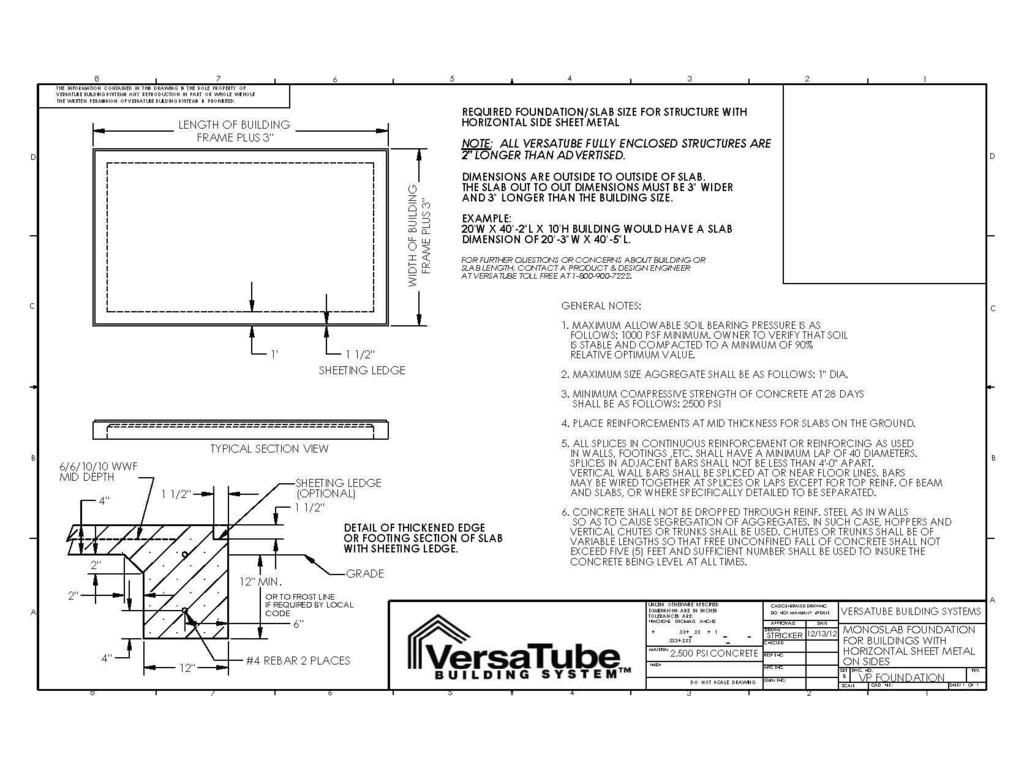
2 ABOUT OUR BUILDINGS Buildings are supplied with on center frame spacing needed to meet the requirements for wind and snow load in your area of the country. It is the customer s sole responsibility to CONFIRM the specific code requirements applicable in city and state in which the product will be erected. The building length will be determined by the number of extension base rails you use. All buildings have starter base rails which are ether 6, 8 or 10 with 2 or 3 vertical pins. These are installed first on ether side at the front of the building. After the starter base rails are in place extension base rails are inserted down the length of the building. These extension base rails will be 2, 3, 8 and 4 for 4 O/C buildings and 10 and 5 for 5 O/C buildings, 6 for 6 on center buildings. NOTE: The length of the frame is 2 longer than the advertised length. (example: a 20 long building is actually 20-2 long). See the last page for a concrete slab drawing. The frame layout for the back and front of the building will be different for each building width and height. Refer to your Design ID-specific Bill of Materials and Sheet Metal List for exact pieces. Window frame kits and windows are optional. We recommend that your building be anchored to a concrete slab with built-in footings and a sheeting ledge. A foundation drawing is provided for the proper slab construction. The building can also be anchored to a larger, pre-existing slab. SAFETY, HAZARD AND MAINTENANCE INSTRUCTIONS IMPORTANT Read the following safety warnings and all instructions in their entirety prior to installation. If you have questions or are missing any parts, contact VersaTube Building Systems Customer Service at before proceeding. WARNING: This structure and its manufactured components are engineered per the instructions and engineering plans provided by VersaTube Building Systems. The use of any framing components or materials in the erection of this structure that are not produced or provided by VersaTube could negatively affect the structural integrity and will negate any warranty provisions. VersaTube Building Systems and its authorized dealers are not responsible for any structural collapse or failure to perform resulting from additions, add-ons, or manipulation of non-versatube components and/or failure to follow approved instructions. WARNING: Metal parts may get hot when exposed to high heat or direct sunlight. Avoid contact with skin and wear protective gloves and clothing to prevent the possibility of burns. WARNING: Avoid installation on windy days as wind may create hazards during the installation process. Wind may blow material or cause partially installed components to collapse prior to being secured or fully installed. The weight of the components or structure may cause serious injury if it should collapse. Replacement cost will be the sole responsibility of the customer. WARNING: Metal conducts electricity and electrical shock hazards exist since the structure is made of metal. During installation or storage, keep the structure and all components away from electrical sources. Make sure that your selected location is away from power lines, underground cables, and any other source of electrical power. Serious injury or even death may occur if contact is made with electrical current. WARNING: If the structure is moved once it has been installed, be certain to inspect all components and conditions and follow each and every step of these instructions to make certain that the structure is securely anchored, properly installed, and aligned. Failure to follow these steps could lead to collapse of the structure and may result in serious risk of injury. WARNING: In the event that your structure is enclosed, be sure to provide proper and adequate ventilation and egress and ingress. Hazardous, poisonous or noxious substances should not be stored in the structure absent proper ventilation and all warnings and instructions of the manufacturer of the substance. Also, proper ingress and egress should be provided to prevent adults or children from becoming trapped inside the structure. WARNING: If metal panels are selected to cover all or a portion of your structure, be careful of the sharp edges which may cause cuts or lacerations. Wear protective work gloves and suitable clothing for protection and always take care when handling metal parts. Always wear safety goggles or glasses when cutting metal or driving/drilling screws. NOTE: The VersaTube Building System is an all domestically produced galvanized tubular steel framing system. Maintenance is required twice annually on particular areas of the framing system i.e. weld seams and cut or raw ends. This maintenance is performed by applying any Zinc coated silver spray paint found at local mass merchant or paint store to these areas twice annually or every six (6) months. NOTE: All sheet metal cladding applied to the VersaTube frame are attached with self drilling screws with a rubber washer. These screws produce small shavings when drilling through the cladding. If the shavings are allowed to sit on the sheet metal for an extended period, rust spots will form and promote deterioration. Metal shavings must be brushed after installation of the sheet metal. Claims reported against rust spots will not be honored by VersaTube Building Systems. PAGE 2


3 ATTENTION: IT IS IMPORTANT THAT YOU READ THE FOLLOWING NOTE BEFORE STARTING THE ASSEMBLY OF YOUR BUILDING NOTE: If during the installation process you have difficulty fitting frame components together, use an adjustable wrench to open end of receiving tube as shown below, left. Close wrench down around bent portion of tube and bend wall outward. It may also be helpful to hit the center of the swaged at the end of the tube to create more of a lead. STRIKE WITH HAMMER Torque Setting Cordless (14 or 18 volt) Or Electric Screw Gun With 5/16" Socket Drive Safety Goggles Or glasses Hammer What you ll need: Utility Knife Hammer Drill One must be able to comfortably reach the peak of the building 10 to 16' high Depending on building width and height. An Extension ladder can also be helpful when installing sheet metal. Masonry Drill Bit 1/2 x 8 Drill depth For Anchoring into Concrete 2 Step Ladders Straw for Blowing dust out of drilled holes Circular saw with Abrasive disk for cutting metal Pencil/Marker and Felt Marker Tape Measure Motor Cycle or Ratchet Straps Work Gloves Wrench, 3/4 & 1/2 Level Chalk Line and Mason Line or Nylon String (May be required to pull frame plumb.) Tin Snips Adjustable wrench Vise grip or other quick clamp Aviation Snips PAGE 3
4 BASIC PARTS LIST: SIZES AND QUANTITIES WILL VARY BY BUILDING WIDTH AND LENGTH REFER TO YOUR VISUAL BOM LOCATED IN YOUR CARE PACKAGE FOR YOUR BUILDING PART NUMBERS AND QUANTITIES. 10 STARTER BASE RAIL Used on buildings with 5 on center post spacing PEAK 10 BASE EXTENSION RAIL Used on buildings with 5 on center post spacing 5 BASE EXTENSION RAIL Used on buildings with 5 on center post spacing 8 STARTER BASE RAIL Used on buildings with 4 on center post spacing 8 BASE EXTENSION RAIL Used on buildings with 4 on center post spacing 4 BASE EXTENSION RAIL Used on buildings with 4 on center post spacing HEIGHT EXTENSION SIDE POST RAFTER T-CONNECTOR L-CONNECTOR COLLAR TIE BRACKET LEFT AND RIGHT 2X2 VERTICAL EXTENSION 2X2 BACK/FRONT BASE RAIL 2X2 VERTICAL HEADER BRACE GARAGE DOOR HEADER, 2X3, SWAGED END. ANGLE BRACKET FLAT BRACKET BACK VERTICAL 2X2X81 3/4 SWAGED ONE END TRUSS BRACE END TIE 2 X 2 CORNER BRACKET TRUSS BRACE CENTER TIE 2 X 2 SWAGED BOTH ENDS HAT CHANNEL (ROOF) BUTYL SEALING TAPE #12 SELF-DRILLING OUTSIDE CLOSURE #10 PAN HEAD, SELF DRILLING SCREW 1 SELF-DRILLING SCREW WITH WASHER, PAINTED PARTS NOT SHOWN ARE 2X3 OR 2X2 STRAIGHT LENGTH PARTS. SHEET METAL AND TRIM ARE SHOWN IN THAT SECTION. 1/2 x 7 CONCRETE WEDGE ANCHOR PAGE 4

5 STEP 1: FOUNDATION CHECK WITH YOUR LOCAL BUILDING OFFICIAL BEFORE YOU POUR A SLAB OR ANCHOR YOUR BUILDING. We recommend that you have a concrete slab poured as a foundation for your building. A foundation drawing is included with the assembly instructions. If you choose to mount the building to an existing slab, the slab should be larger than the outside building dimensions by at least 3 front to back and side to side. NOTE: The length of the frame is 2 longer than the advertised length. (example: a 20 long building is actually 20-2 long). PLEASE SEE THE LAST PAGE FOR CONCRETE SLAB DRAWING. STEP 2: BASE RAIL ASSEMBLY Place the starter base rails in the front corners of the building flush with the sheeting ledge on the sides of the slab. (See FRONT DETAIL below) The outside dimension of the base rails should be your building width. The starter base rails are either 4-2, 5-2, 6-2, 8-2 or 10-2 long with 2 or 3 welded vertical pins. Insert extension base rails into the starter base rails as shown until you get to the desired building length. NOTE: the last base rails that you insert to get to your building length may be 1 PIN base extensions. The vertical pins should be on 2, 3 4, 5 or 6 centers. Measure the distance from the end pin on each base rail to the first pin on the next inserted base rail and adjust the joint so that all the pins are on 4, 5 or 6 centers. (22, 34, 46, 58 or 70 between pins). It may be helpful to cut a spacer board to use as a guide for pin spacing. Now take a measurement across the diagonals of the frame to check it for square. Adjust the frame until the measurements are equal. When you are sure that you have all the base rails in the proper location, fasten each joint with two #12 selfdrilling screws on the top of the base rail. FRONT VIEW #12 SELF-DRILLING SCREW DIAGONAL DIMENSIONS SHOULD BE EQUAL JOINT DETAIL SIDE VIEW PLACE THE END OF THE STARTER RAIL WITH 2 ANCHOR HOLES IN THE CORNER OF THE BUILDING 4, 5 OR 6 (1) PIN EXTENSION BASE RAIL 4, 5 OR 6 (2) PIN EXTENSION BASE RAIL 1 1/2 PIN STARTER BASE RAIL (2) OR (3) PINS; NO SWAGE 1 1/2 ANCHORING THE BASE RAILS: Check with your local building official to see if concrete expansion bolts are acceptable in your area. Some regions may require adhesive anchors. We recommend 1/2 x 7 expansion anchors with a 1/2 flat washer. INSTALLATION: Blow dust residue out of holes before applying your anchor. Use a 1/2 concrete bit in a hammer drill to drill a 5 deep hole in the slab. Use the anchor hole in the tube as a guide. Place the washer and nut on the top of the bolt with about 2 threads showing. Tap the bolt into the hole with a hammer and tighten the nut until it is good and snug. Do not crush the base rail tube. 7 PAGE 5
6 ANCHORING TO GROUND WITH CONCRETE PIERS DIGGING HOLES FOR CONCRETE Mark the locations of the rails and the anchor holes on the ground. Move the base rails to one side and dig holes at each anchor point for concrete. You may want to rent a gas-powered post hole digger with 12 diameter auger for this job. HOLE SIZE: Hole size to be a Minimum of 12 in diameter and 24 deep. Check with Local Building Officials for frost line depth to ensure the proper anchoring depth for your specific building. ANCHORING Move the base rails back into position over the holes. Re-measure to make sure the rails are in the proper location and insert the ground anchor into each anchor hole. Ensure that the base rails are square before pouring concrete (see layout on page 5). Mix up concrete and pour into holes up to ground level. You may want to rent a mixer for this job. Before the concrete sets, re-check all your dimensions to make sure the frame is square and has the proper width. Let the concrete cure overnight before installing the Roof/Wall assemblies. BASE RAIL CONCRETE VERSATUBE 30 REBAR GROUND AN- PAGE 6
7 STEP 3: ROOF/WALL FRAME ASSEMBLY On the ground, assemble (1) peak, (2) rafters, (2) side posts, and (2) height extensions if required. Before you fasten the joints with screws take a measurement across the top and bottom of the assembly as shown. This outside measurement is the outside size of your building. Try to keep the joint spacing on both sides of the assembly equal. It is very helpful to drive stakes into the ground at the width of the building and use them to set the dimension at the bottom of the assembly. You should set the bottom dimension before you adjust and set the top dimension. Now, fasten the joints with #12 self-drilling screws. 4 screws in the peak to rafter and side post to rafter joints and 2 screws in the height extension joints. See details below. NOTE: You can use the first assembly as a template to assemble the remaining Roof/Wall Frames. Slight dimples in tube should be on the same side of structure EXTENSION HEIGHT DRIVE STAKES INTO THE GROUND TO CREATE A FIXTURE FOR SETTING THE BOTTOM DIMENSION AT YOUR BUILDING WIDTH. BUILDING WIDTH HEIGHT EXTENSION - FOR ANY FRAME OVER 8 TALL RAFTER BUILDING WIDTH PEAK SIDE POST HEIGHT EXTENSION JOINT PEAK TO RAFTER JOINT INSTALL CORNER BRACKETS (SEE BELOW) BOTH CORNERS SIDE POST TO RAFTER JOINT #12 SELF-DRILLING SCREW CORNER BRACKET NOT FOLDED INSTALLATION OF CORNER BRACKETS Corner brackets must be installed on all side post corners (eave corners). The corner brackets will come in the kit in the straight form and must be folded to fit the eave corner. Fold the bracket, place it on the side post corner, make sure that it is flush with both surfaces and fasten the bracket on both sides of the assembly with 4 screws per side. #12 x 3/4 self-drilling screws. FLUSH FLUSH CORNER BRACKET FOLDED PAGE 7
.")
8 BRACING: TYPE (1) COLLAR TIE, TYPE (2) COLLAR TIE WITH VERTICAL, TYPE (3) COLLAR TIE WITH WEB BRACES Bracing on buildings is determined by the width of the building and the wind and snow load in your county. If you have a large wind or snow load, a modified Type 3 truss may be used (Types 6 & 7). TYPE 1 TYPE 2 TYPE 3 COLLAR TIE COLLAR TIE WITH VERTICAL BRACE COLLAR TIE WITH WEB BRACING COLLAR TIE ASSEMBLY: VISIT FOR COLLAR TIE VIDEO FOR 2 x3 FRAMING VISIT FOR CALLAR TIE VIDEO FOR 2 x4 FRAMING The Collar Tie (Type 1 brace) if required may be a single 2 sq. tube or a 2-piece collar tie (width dependent). All other Collar Ties are made up of 3 parts: (1) Center Tie 2 x 2 x 111 long swaged (reduced) on both ends and (2) end ties. End Ties are 2 square tube. Place an End Tie on both ends of the Center tie and fasten each joint with (6) #12 selfdrilling screws. Place screws on one side of the assembly as shown. Note: make sure the assembly is straight when you install screws. When the collar tie is centered, the end ties should be 18 from the outside wall of your structure. Install a left and right Collar Tie Bracket on both ends as shown. Use one screw in each hole. For structures 30 W or larger, Collar Tie Brackets will be provided for the front and back of each collar tie assembly. COLLAR TIE BRACKET LEFT & RIGHT CENTER TIE END TIE END TIE SCREW PATTERN (BOTH ENDS) LEFT COLLAR TIE BRACKET. THE RIGHT BRACKET IS A MIRROR OF THE LEFT. ASSEMBLY OF COLLAR TIE TO ROOF/WALL FRAME: The collar tie must be centered in the frame. Take a measurement from the end of the side post to the edge of the collar tie bracket on both ends of the collar tie. Adjust the collar tie side to side until the measurements are equal. Fasten with (6) selfdrilling screws on each side of the assembly. EQUAL MEASUREMENT ON BOTH ENDS OF COLLAR TIE #12 SELF-DRILLING SCREW PAGE 8
9 INSTALLING VERTICAL BRACE FOR BRACE TYPE (2) VISIT h ps:// FOR ASSEMBLY VIDEO FOR 2 x3 VISIT FOR ASSEMBLY VIDEO FOR 2 x4 The Center Vertical Brace is a 1 1/2 square tube. Fasten the vertical brace to the Collar Tie and the Frame Peak with Single Purlin Brackets. Use two screws in the bracket tongue and one screw in each side flange as shown. Fasten the brackets to the vertical brace first. Make sure that the Collar Tie assembly is straight before you fasten the brace to the Collar Tie and Peak. Place all parts in the assembly and adjust before installing any screws. SINGLE PURLIN BRACKET PEAK #12 SELF-DRILLING SCREW VERTICAL BRACE ASSEMBLING WEB BRACING: VISIT FOR ASSEMBLY VIDEO FOR 2 x3 VISIT FOR ASSEMBLY VIDEO FOR 2 x4 STEP 1: INSTALLING THE PEAK WEB BRACKET Measure up from both ends of the peak to find the center and make a mark. Place a Web Bracket centered at your mark and pressed against the bottom of the peak. Fasten the Bracket to the peak with 3 self-drilling screws as shown in detail. PEAK PEAK BRACKET 1 BRACKET 3 BRACKET WEB BRACE 1 BRACKET 2 WEB BRACE 2 WEB BRACE 3 WEB BRACE LENGTH WEB BRACE 1 STEP 2: INSTALL TWO OF WEB BRACE 1: Place one of the brace ends on top of the Web Bracket tab and the other brace end on the bottom of the tab. Join the parts with a 3/8 x 1 1/4 hex bolt, lock washer and hex nut. Do not tighten at this time. It may be necessary to lift the frame to insert bolt. STEP 3: INSTALL WEB BRACE 2: Loosely attach Web Bracket 2 to the other end of Web Brace 1. Place the Web Bracket on the Collar Tie (make sure the collar tie is straight and fasten the face of the bracket to the collar tie with a selfdrilling screw. Remove the hex nut and attach one end of Web Brace 2 to the Web Bracket 2 assembly (like the first assembly, one brace end should be on one side of the web bracket tab and one on the other). Now, Loosely attach Web Bracket 3 to the other end of Web Brace 2 and fasten the bracket to the under side of the rafter. Repeat assembly for remaining Web Brace 2. (See diagram on next page) PAGE 9
10 WEB BRACKET 1 PEAK WEB BRACKET 3 WEB BRACE 2 VISIT THE LINKS BELOW FOR ASSEMBLY TUTORIAL VIDEOS FOR THE FOLLOWING: WEB BRACE 1 WEB BRACKET 2 LOCATE BRACKET ON COLLAR TIE. INSERT ONE SCREW HERE. UNDO ASSEMBLY AND INSTALL BRACE 3. REINSTALL HARDWARE 2 x3 WEB w/ KNEE BRACES h ps:// 2 x4 WEB w/ KNEE BRACES h ps:// 2 x3 WEB w/ MID KNEE BRACES h ps:// 2 x4 WEB w/ MID KNEE BRACES h ps:// 2 x3 WEB w/ LONG KNEE BRACES h ps:// 2 x4 WEB w/ LONG KNEE BRACES h ps:// STEP 4: ASSEMBLING WEB BRACE 3: WEB BRACE 3 IS 24 LONG ON ALL BUILDINGS WITH A TYPE 3 TRUSS. WEB BRACE 3 WILL BE HALF YOUR SIDE WALL HEIGHT FOR A TYPE 6 OR FULL SIDEWALL HEIGHT FOR A TYPE 7 TRUSS BRACE. Locate the edge of the web bracket at the end of the side post as shown. Attach the upper Web Bracket with 3 self-drilling screws. Now, fasten Web Brace 3 to the upper Web Bracket with a hex bolt, lock washer and hex nut. (Do not tighten at this time) Loosely attach a Web Bracket to the lower end of Web Brace 3 and place it against the side post. Re-check the building dimension across the bottom of the frame before attaching lower bracket to side post. Now, attach the face to the side post with a screw, remove the hex nut, let the bolt drop down and install the two screws in the side of the Web Bracket. Now, reinstall the bolt, lock washer and nut. Repeat assembly for remaining Web Brace 3 on the other side of the frame. WHEN ALL BRACES ARE IN PLACE, TIGHTEN ALL HARDWARE. The nut size is 9/16. You may also need to hold the bolt head with pliers. UPPER WEB BRACKET INSTALL UPPER THIS WEB SCREW BRACKET FIRST IN FACE WEB BRACE 3 WEB BRACE 3 SIDE POST LOWER WEB BRACKET INSTALL THIS SCREW FIRST IN FACE PAGE 10

11 STEP 5: MARKING THE HAT CHANNEL PLACEMENT ON THE FRAMES AHEAD OF TIME Once you have the trusses assembled take time to stack them on top of each other, ensuring that the top of all of the frames are squared up and all joints lined up. Now refer to your Care Package for the on-center spacing of your hat channel. Use one of the Pre-cut pieces of hat channel to mark the location on the roof frame surface. (DO NOT CUT A PIECE OF HAT CHANNEL) First, mark the outside locations at the eave corner. Next, mark the on-center spacing according to your Care Package, use the on-center marks and center the hat channel vertically as shown in the illustration. Then mark a line across the trusses locating both edges of the hat channel. *Please See your Care Package that was ed to you, for the Hat Channel spacing on the roof of the building.* HAT CHANNEL USED FOR MARKING SPACING Please Note: On-center spacing of hat channel differs per snow and wind load requirements. STAKES You can measure and locate each hat channel as you go or mark the locations of all the channels as previously mentioned. In the event that the previous step was missed you are still able to mark the hat channel locations on the front and back frame sections and snap a chalk line the length of the building to mark the hat channel locations on all of the interior frame sections, this is more challenging though, and you must ensure the trusses are level and plum. Hat cannel installation will be addressed on page 16. These steps are meant to save you time and create a better building experience. STEP 6: INSTALLING ROOF/WALL FRAMES SECTIONS TO BASE RAILS BASE RAIL PIN TIP: Place bottom of side posts on base rail pins at an angle. Raise frame section and drop it onto pins at the same time on both sides of the carport. Tap lightly on the side post with a hammer if parts do not drop into place. NOTE: This assembly will require at least two people. Larger frames may require more people or lifting equipment. When raising a larger frame, the third person can walk the center of the frame up a ladder placed inside the building. Start at one end of the building and place a Roof/Wall frame assembly (one with no truss brace) on the first base rail vertical pins. Fasten vertical joints with two screws each. Keep the screw heads away from the outside of the building where sheet metal may be installed. Check the bottom ends of the side posts or height extensions for dimples that might interfere with assembly to base rail pins. Dimples must be removed. (See page 2.) Repeat this assembly until all Roof/Wall frame assemblies are installed. (Remember, NO Truss Braces on front or back frames) As you begin the installation of the truss frames we recommend that you brace the one end wall of the building. Make sure that the end wall is plumb and attach angle braces from the end wall side posts to the lower portion of the next frame section side posts. You can use wood or metal for this job. Place a brace on both sides of the building. You can clamp the braces in place or use self-drilling screws. If you use screws you may want to mount the braces to the outside of the frame. Braces could also be attached to a wood stake driven into the ground 5 or 6 away from the back of the building. The frames should be on 4, 5 or 6 centers. Again, Please refer to your Care Package for your buildings oncenter spacing. NOTE THAT THE END FRAME SECTIONS DO NOT HAVE TRUSS BRACES. #12 SELF-DRILLING SCREW PAGE 11
12 SQUARING UP YOUR FRAME Before you install sheet metal, you may want to check the Roof/Wall assemblies to make sure they are plumb and square and that the side post heights are equal. To do this, first check the front and back Roof/Wall sections to make sure that they are plumb side to side. Check the outside of the side post. If adjustments must be made, you can drive a wooden or metal stake into the ground about 8 from the building and use a Motor Cycle strap or Ratchet strap to pull the side post into plumb. Place a clamp on the side post as shown and attach the strap above the clamp. When the front and back sections are plumb (side to side), tie two strings from the front side post to the back side post at the bottom and top of the bend radius as shown. These strings will let you see which sections are high, low or out of plumb. If the side posts are high or low, remove the joint screws and raise the low posts and hammer down the higher posts as much as possible. Reinstall the screws in a new location. Check the height of the side posts on both sides of the building. The straps should remain in place until several runs of roof metal have been installed. Note: This is not a critical step, but it may improve the appearance of your building. If side posts are out of plane with the other side posts more than 1/4, it may be visible. CLAMP MOTOR CYCLE STRAP SIDE POST HAMMER STRING STEP 7: INSTALLING SOLID WALL BASE RAILS The Back Enclosure is the frame components that enclose the back of the building. Refer to Design ID-specific Bill of Materials for exact pieces. If you do not have a solid wall, skip to Step 7. Layout the Base Rail components as shown in the separate illustration for your building size. Note that all back frame components are 2 square tubing. See separate illustration for length dimensions of base rail tubes. The base rail assembly is made up of straight length 2 square tubes and T-Connectors. When you have all of the base rail assembly together, place the assembly between the back side base rails of the building. Fasten the end base rails to the pins of the side base rails with Angle Brackets. The spaces between the vertical pins should be equal. Fasten joints with two 1 self-drilling screws on top of the base rail. Anchor the T-Connectors to the concrete slab or footing as you did the side base rails with 1/2 x 7 wedge anchors. STEP 8: INSTALLING SOLID WALL VERTICALS The verticals on the solid wall will either be a single 2 square tube or a two piece vertical. If it is a two piece assembly, the bottom of the vertical is a 2 square x 81 3/4 tube with one swaged (reduced) end. The top of the verticals are 2 square tubes. The length is shown on your Bill of Material and separate illustration. Assemble all verticals as prescribed by your illustration. (do not install screws at this time) Place the assemblies on the base rail pins, plumb the assembly, slide the extension tube up to touch the rafter or peak and attach it with a Flat Bracket on the inside of the building. It may help to attach the flat bracket to the vertical extension before you install the assembly. Let 2 of the bracket extend beyond the end of the extension. NOTE: PLEASE REFER TO THE STRUCTURAL DRAWINGS IN YOUR CARE PACKAGE FOR SPECIFIC BACK & FRONT ENCLOSURE DETAILS. NOTE: This is an example Solid Wall. This does not reflect your unique Design Your Own Solid Wall. FLAT BRACKET TYPICAL ON ALL BUILDINGS (ON INSIDE OF BUILDING) #12 SELF-DRILLING SCREW PAGE 12
13 STEP 9: INSTALLING VERTICALS FOR END WALLS WITH OPENINGS Refer to the separate illustration for your end wall. Join the Base Rail tubes and (L), (T) or (U) connectors as shown. The Base Rails are all 2 square tubes. See separate illustration for tube length. Measure and mark the location for the base rails and anchor the L, T or U connector combinations with expansion bolts as you did the side base rails. NOTE: Leave the nuts slightly loose so you can install the vertical tubes. Attach the end base rails to the side base rail pins with Angle brackets as you did on the solid wall base rail ends after the vertical tubes are installed. Assemble the 2 x3 Garage Door Vertical Tubes (see illustration for parts and location). Attach a Flat Bracket at the top as shown and stack the vertical Door Jamb tubes on the L-Connectors or U-Connectors as shown. Plumb the Door Jambs and attach the top portion of the assembly to the rafter or peak. Note that the Flat Bracket should be on the inside of the building. Be sure to leave a space between the Door Jambs to install the 2 x3 door header. Your Garage Door Verticals and Header will be made of a single 2 x3 OR two 2 x3 tubes. Assemble the Door Header components as listed in your illustration and fasten them to the Door Jambs with Angle Brackets on the top of the header. Now, install the vertical Header Brace (2 square tube) in the center above the Door Header with 2 Angle Brackets at the bottom and a Flat Bracket at the top on the inside of the building. The brace should be plumb. You may find it easier to attach the brackets to the header brace on the ground (see detail). If you have a pedestrian door or window on your end wall, those components will be made from 2 square tubing. The vertical jamb for your pedestrian door will be 2 square x 81 3/4 and the door header tube will be a 2 square tube long enough to reach the closest verticals. Attach the door header tube to the closest verticals and door vertical with angle brackets. Attach the door jamb to the base rail with a flat bracket. The base rail under your pedestrian door can be cut out. NOTE: If you cut out the base rail, make sure your anchor hole in the T connector is not being cut out. Make your cut the rough opening width recommended by your door manufacturer plus 2. Drop the door jamb to the ground and use the flat bracket horizontally to attach the jamb to the base rail. For windows, you will receive (2) 2 square tubes long enough to reach the closest verticals and (2) 2 square tubes the height of your desired window opening. Attach all tubes together with angle brackets and attach window framing to verticals with angle brackets. (not shown) NOTE: PLEASE REFER TO THE STRUCTURAL DRAWINGS IN YOUR CARE PACKAGE FOR SPECIFIC BACK & FRONT ENCLOSURE DETAILS. NOTE: This is an example End Wall. This does not reflect your unique Design Your Own End Wall. SEE BUILDING DRAWING FOR VERTICAL PART LOCATION ON INSIDE OF BUILDING 2 DOOR VERTICAL ASSEMBLY L-CONNECTOR & BASE RAIL DETAIL. MOUNT U- CONNECTORS THE SAME T CONNECTOR LEAVE NUT LOOSE UNTIL VERTICALS ARE INSTALLED BASE RAIL TO SIDE BASE RAIL PIN MAKE SURE ANCHOR IS ON OUTSIDE REMOVE FLAT BRACKET PAGE 13
14 STEP 10: ASSEMBLE EAVE SIDE WALK DOOR FRAME (CUT OUT BASE RAIL) VISIT FOR WALK DOOR TRIM APPLICATION VIDEO The Door Frame consists of a Header Tube 2 x 3 x 45 3/4 long (for 4 OC), 57 3/4 long (for 5 OC) or 69 3/4 (for 6 OC) and a Door Jamb 2 x 3 x 81 3/4. These combine with the side post to create the frame for your door. The following assembly instructions are a for the flange mounted door. The door will open to the outside of the building. The first step is to choose the frame bay (opening) where you want to install the door. The door will be located in the frame to the side away from the anchor bolt. Do not chose an opening with two anchor bolts. We recommend that the base rail be cut out where the door will be located. This will allow the threshold portion of the door frame to sit down on the slab and not cause a trip issue. If your building is not being built on a slab you can mount the door frame on the base rail. To cut out the base rail, use a metal cutting blade in a reciprocating saw. Mark a line on the base rail 38 from the side post. Place the line on the top and the side of the base rail. Now, with the reciprocating saw, cut the base rail 3/16 from the side post (as close as you can to the weld) then cut the base rail at your marked line. Remove the section of base rail and you are ready to install the door. Place the door in the opening to check the fit. The door will open to the outside. Cut the 2 x 3 x 81 3/4 door jamb tube down to 79 3/4. (If you are not cutting out the base rail, do not cut down the jamb post) You can use a metal cutting blade or an abrasive disk in your saw to cut the tube. Pre-attach a flat bracket to one end of the door jamb tube on the 2 side of the tube. Allow 2 of the bracket to hang over the end of the tube. The bracket will be attached on the inside of the building to the base rail. Attach an angle bracket to the top of the tube flush with the end and centered in the 3 side of the tube. Before you attach the angle bracket, set the tube in place and make sure that the flat bracket is on the inside of the building and the angle bracket is facing away from the door opening. Attach the brackets with #12 x 3/4 self-drilling screws. Attach an angle bracket to both ends of the header tube. Let the brackets extend 1/8 past the ends of the tube. The outside to outside dimension on the brackets should be 46 for 4 on center frames, 58 for 5 on center frames or 70 for 6 on center frames. Follow installation tips for your door BEFORE installing sheet metal on the exterior of your building. DOOR HEADER TUBE 2X3X45 3/4, 57 3/4 OR 69 3/4 ANGLE BRACKET 1/8 Both ends BUILDING SPACING ANGLE BRACKET DOOR JAMB POST 81 3/4 OR CUT DOWN TO 79 3/4 FOR DOORS WITH CUT AWAY BASE RAIL. FLAT BRACKET TO INSIDE OF BUILDING 2 OVERHANG 38 CENTER ANGLE BRACKET ON 3 SIDE OF TUBE FIRST CUT CLOSE TO WELD #12 SELF-DRILLING SCREW 40 PAGE 14
15 STEP 11: INSTALLATION OF OPTIONAL WINDOW FRAME VISIT FOR WINDOW TRIM APPLICATION VIDEO If you are installing an optional window frame, Measure your window to determine the rough opening that you will need. Locate the vertical window frame tubes needed. Mount the lower horizontal window frame tube to the side posts as shown at right with angle brackets. The tube should be level. Pre-mount angle brackets to the vertical frame tubes. Center and properly space them on the bottom tube to give you the correct rough opening width. Fasten them in place. Now, install the top horizontal frame tube with angle brackets. Square and plumb the vertical tubes and attach them to the top frame tube. The Window Kit includes: (2) Horizontal frame tubes 2 x 3 x 45 3/4 for 4 OC frames, 2 x 3 x 57 3/4 for 5 OC frames, OR 2 x 3 x 69 3/4 for 6 OC frames, Part # 2X3-WDH-(X). (X) is equal to the on-center spacing 4,5 OR 6. (3) Vertical frame tubes 2 x 3 x height of window. Part # 2X3-WV-(Y), (Y) is equal to the height of the window. i.e. 2,3,4,or 5 (ft.) (8) Angle brackets with screws. ANGLE BRACKET HORIZONTAL FRAME TUBE PART # 2X3-WDH-(X) 2 x 3 x 45 3/4, 57 3/4 OR 69 3/4 DESIRED HEIGHT VERTICAL FRAME TUBE PART # 2X3-WV-(Y) THE HEIGHT OF YOUR WINDOW WAS DETERMINED BY YOU IN THE DESIGN YOUR OWN OPTIONS THAT YOU SELECTED. DESIRED HEIGHT HORIZONTAL FRAME TUBE PAGE 15
16 STEP 12: INSTALLING HAT CHANNEL PURLINS ON ROOF OF BUILDING The purlins on the roof of you building are Hat Channel. Most of the hat channel that you install will be 8 long for buildings on 4 centers, 10 long on buildings that are 5 on-center, or 12 long on buildings that are 6 on-center. In some cases you may have shorter pieces that are the same as the on-center spacing of your building. Please See your Care Package that was ed to you, for the location dimensions for the Hat Channel on the roof of the building. You can measure and locate each hat channel as you go or mark the locations of all the channels on the front and back frame sections and snap a chalk line the length of the building to mark the hat channel locations on all of the interior frame sections. Before you start the installation of hat channel purlins on the roof we recommend that you brace the one end wall of the building. Make sure that the end wall is plumb and attach angle braces from the end wall side posts to the lower portion of the next frame section side posts. You can use wood or metal for this job. Place a brace on both sides of the building. You can clamp the braces in place or use self-drilling screws. If you use screws you may want to mount the braces to the outside of the frame. Braces could also be attached to a wood stake driven into the ground 5 or 6 away from the back of the building. With the back wall supported, you can measure and note the distances from one frame to the next at the base rail and use that dimension to position the frames at the top of the building as you install the hat channel purlins. The frames should be on 4, 5 or 6 centers. Attach the hat channel to the frame with #12 x 3/4 self-drilling screws. See the illustrations on the next page for purlin HAT CHANNEL ATTACH HAT CHANNEL TO FRAME WITH #12 X 3/4 SELF-DRILLING SCREWS 1 FLUSH START HAT CHANNEL 1 FROM END OF FRAME CLAMP OR SCREW BRACES TO FRAME CROSS OVER JOINT Where purlin crosses over a frame section. BUTT JOINT Where two purlins come together. ALTERNATIVE BRACE TO THE OUTSIDE OF THE STRUCTURE. PAGE 16

17 STEP 13: INSTALLING RAT TRACK HAT CHANNEL Rat Track is additional Hat Channel Girts that are installed on top of the collar tie to assist with longitudinal strength. Rat track will be included with all buildings 30 Wide or larger. The rat track will start on the second frame and end on the second to last frame. For 30 W, you will receive 3 runs of Hat Channel (40 W 4 runs; 50 W 5 runs, etc). Evenly space the hat channel on your collar tie and attach with (2) #12 x 3/4 self-drilling screws per connection. 30 RAT TRACK EXAMPLE SHOWN EVENLY SPACED ON THE COLLAR TIE PAGE 17

18 STEP 14: INSTALLING SIDE METAL PANELS SEE SHEET METAL TAKE OFF IN YOUR CARE PACKAGE FOR SHEET METAL PANEL LENGTHS The sheet metal panels provided by VersaTube will be 8-2 or 12;-2 long if your building is on 4 centers. If you building is on 5 frame centers the side panels will be 10-2 long. For 6 centers the side panels will be 12-2 long. Start your first run of sheet metal panels at the eave corner of the building. Start at the back of the building. The sheet metal panels have an under lap and an overlap edge. The under lap edge is a complete rib with a small flange. The overlap edge is a partial rib. The under lap edge will always be place to the top and the overlap edge to the bottom. Use #12 x 1 painted, self-drilling screws to install sheet metal panels. NOTE: All sheet metal cladding applied to the VersaTube frame are attached with self drilling screws with a rubber washer. These screws produce small shavings when drilling through the cladding. If the shavings are allowed to sit on the sheet metal for an extended period, rust spots will form and promote deterioration. Metal shavings must be brushed after installation of the sheet metal. Claims reported against rust spots will not be honored by VersaTube Building Systems. UNDER LAP EDGE #12 x 1 PAINTED, SELF-DRILLING SCREW OVERLAP EDGE Place screws about 1 from the major ribs as shown. Do not install screws above the bottom rib until the next course of sheet metal is installed. UNDER LAP EDGE FLUSH WITH COR- NER BRACKET Do not install screws at the end of the panel until the next panel is in place. Lap panel two 2 over panel one. No screws above bottom rib until next lower panel is installed. PAGE 18
19 INSTALLING ADDITIONAL COURSES OF SIDE METAL PANELS When you have completed the installation of the first course of side wall panels at the eave of the building, start the second course at the same end of the building. Insert the under lap edge of the panels under the overlap edge of the panels in the first course. Attach the panels with screws as you did the first course of panels. Once again, leave the screws out of the lower edge so you can insert the lower course of panels. Continue installing panels until you get to the last course at the bottom of the side wall. You will probably have to cut the last course of panels to fit. Take a measurement from the center of the lower edge to the bottom of the base rail. Subtract about 1/8 from that measurement. Now, mark the lower panel on the under side of the panel. Cut the length of the panel with a circular saw with a metal cutting blade. (The good side of the panel should be facing down when you make the cut. Make sure you are wearing eye and ear protection when you cut these panels. Repeat the installation of side panels on the other side of the building. UNDER LAP EDGE LOWER PANEL Measure lower panels from center of under lap edge rib. Mark on the under side of the panel and cut the panel with the good side down. Measurement 1/8 PAGE 19
20 STEP 15: INSTALLING BACK WALL SHEET METAL PANELS SEE SHEET METAL TAKE OFF IN CARE PACKAGE FOR SHEET METAL PANEL LENGTHS The length of the sheet metal panels for the back end wall will vary depending on the building width, Panels will be sized to overlap at one of the vertical frame members, typically the center frame member. In order to get the ribs on the end wall to line up with the side wall panels we recommend that you start your first run (course) of sheet metal panels at the eave corner of the building with the ribs on the back of the building matching up with the ribs on the side wall. You may want to measure up from the bottom of the building or snap a chalk line from one side to the other to make sure that the first course of panels is straight and level. Remember to place the under-lap edge to the top. Panels installed above the first course will have to be market on the back and trimmed to be flush with the top of the hat channel roof purlins. The under lap edge of lower panels will slid under the overlap edge of the course above so do not install screws above the lower rib on the higher course of panels until the lower course has been installed. Trim the bottom course to fit just above the bottom of the base rail. BACK WALL PANEL LAYOUT SET THIS TOP PANEL IN PLACE. MARK ON THE BACK AT THE TOP OF THE HAT CHANNEL. REMOVE THE PANEL AND CUT. SCREW PANEL IN PLACE SCRAP SCRAP INSTALL THIS PANEL OR PANEL COURSE FIRST TRIM TO FIT AT BOTTOM MATCH END WALL PANEL RIB TO SIDE WALL RIB AT BOTH EAVE CORNERS SIDE WALL SHEET METAL TOP RIB PAGE 20
21 STEP 16: INSTALLING TRIM ON THE GARAGE DOOR FRAME VISIT: FOR GARAGE TRIM APPLICATION VIDEO ANGLE TRIM INSTALLATION: Cut two pieces of Angle Trim to fit for both sides of the garage door opening, from the concrete slab to the bottom of the door header, for each door. This will trim out the door jambs. The width of the garage door openings vary per customer s selection. For the door header angle trim, measure and use the length of trim that applies, cut to length if needed. If opening is wider than the 10 trim provided then measure the remaining distance, then add 3 for an overlap where applicable. i.e. If you have one 16 wide garage door you will be using (1) 10 piece of Angle Trim and you will need to cut a 6-3 piece of Angle Trim. The 6-3 trim will overlap the 10 piece by 3 to trim out the under side of the door header. Please see the Sheet Metal Take-off in your Care Package for additional trim information. Fasten the Angle Trim with Painted #12 x 1 Self-Drilling Screws with Rubber Washers every 2. ORDER OF INSTALLATION: (1) ANGLE TRIM, (2) J-TRIM, (3) SIDE J-TRIM, (4) TOP J-TRIM 2 ANGLE TRIM #12 X 1 PAINTED, SELF-DRILLING SCREW WITH RUBBER WASHER 1 1/2 FRONT FRONT DETAIL USE #12 X1 PAINTED, SELF DRILLING SCREW WITH RUBBER WASHER. MEASURE THE OPENING FOR THE DOOR, YOU WILL NEED (1) 10 PIECE, CUT TO LENGTH IF NEEDED. IF AN ADDITIONAL PIECE IS NEEDED, MEASURE THE REMAINING DISTANCE THEN ADD 3 FOR THE OVERLAP. CUT DOOR JAMB ANGLE TRIM TO FIT FROM SLAB TO BOTTOM OF DOOR HEADER. PAGE 21
22 INSTALLATION OF J-TRIM AROUND GARAGE OVERHEAD DOOR: VISIT: FOR GARAGE TRIM APPLICATION VIDEO Cut two pieces of J-Trim to fit from the bottom of the sheeting ledge to the top of the door jamb (bottom of the door header). This will be the side J-Trim. If your building is on a slab with no sheeting ledge, cut the trim to fit from the slab to the under side of the door header. Top J-Trim: If you have a 9 wide door cut a piece of J-Trim 110 long and cut two 1 slits in both ends as shown in detail. The slits will create tabs that will fold down into the door jamb Side J-Trim. See illustration. If you have a 16 wide door you will need to cut a 6-5 long piece of J-Trim that will overlap a 10 piece of J-Trim 3. The width of the garage door openings vary per customer s selection. For the door header width, measure and use the length of trim that applies, cut to length if needed. If opening is wider than the 10 trim provided then measure the remaining distance, then add 3 for an overlap where applicable. Attach the Side J-Trim first at both ends and two additional places equally spaced from top to bottom with Pan Head Self- Drilling Screws. See illustration below for location of Side J-Trim. Place the Top J-Trim on top of the Side J-Trim along the door header. Fold the end tabs, that you created with the 1 slits, down into the J-Trim channel and attach the at both ends and two on three places down the length with Pan Head, Self-Drilling Screws. (Be sure to place one screw in the overlap joint if you have one.) J-TRIM DOOR HEADER PAN HEAD, SELF-DRILLING SCREW FRONT 1 SLIT OVERLAP TOP J-TRIM MAKE TWO CUTS 1 LONG AND FOLD TAB DOWN INTO J-CHANNEL ON BOTH ENDS LIKE WALK DOOR AND WINDOW DOOR JAMB, TOP VIEW, RIGHT SIDE OF DOOR SIDE J-TRIM J-TRIM OUTSIDE OF BUILDING PAGE 22
23 STEP 17: INSTALLING FRONT WALL SHEET METAL PANELS The length of the sheet metal panels for the front end wall will vary depending on the building width. Please see SHEET METAL TAKE-OFF located in your CARE PACKAGE for gable end panel lengths. Panels will typically be half the width of the building plus 1. This will allow the panels to overlap 2 at the center frame member. In order to get the ribs on the end wall panels to line up with the side wall panels we recommend that you start your first run (course) of sheet metal panels at the eave corner of the building with the ribs on the front of the building matching up with the ribs on the side wall. You may want to measure up from the bottom of the building or snap a chalk line from one side to the other to make sure that the first course of panels is straight and level. Remember to place the under-lap edge to the top. The first panel that you install will have to be trimmed to fit the top of the door opening. Set the panel in place with both ends matched up with the top ribs on the side panels if you have full length sheet metal panels or with the chalk line if you have two or more panels. Mark the door opening on the inside of the panel. Subtract about 1/4 from the line that you mark and cut the panel with your tin snips and your circular saw with a metal cutting blade. Install the panel with screws above each major rib. Do not install screws above the bottom rib until the next lower panel is installed. Set the top course of panels in place, mark and cut them as you did the top panel/panels on the back of the building. Install the panel/panels. Now measure the distance from the edge of the building frame to the door opening, subtract 1/4. This will be the length of the lower panels on the sides of the garage door opening. Insert and attach the lower panels on both sides of the door opening. These panels will slide into the J-Trim around the door. You will have to trim the bottom panels to fit before they are installed. SCRAP SCRAP INSTALL THIS PANEL FIRST SCRAP SHORTER PRE-CUT PANELS SCRAP SCRAP PAGE 23
24 STEP 18: CORNER TRIM Before you install the corner trim you must install Outside Foam Closures. The foam closured are grey foam strips with Notches cut out to match the contour of the sheet metal panel ribs. The closures have an adhesive strip on one surface. Peal off the protective paper and install the strips to the sheet metal panels in the corners of the building as shown. The corner trim for your building is angle trim 3 x 3 x 10 long. If your building is 10 at the eave you will not have to cut the corner trim. If your building is under 10 at the eave cut the trim to fit. If your building is over 10 you will have to cut 4 extension pieces of trim and overlap them as shown below. Cut the extension to allow about 5 of overlap. Place the extension pieces on all 4 corners of the building at the bottom. Screw the trim to the building with #12 x 1 self-drilling screws painted the color of the trim. Place the screws in the trim to hit the center of every other major rib in the sheet metal panels. Do not install screws at the top of the angle until a longer 10 piece is installed. Now place a 10 piece of trim on each corner of the building with the top of the trim 1 above the top of the side sheet metal. The trim should overlap the 30 piece of trim at the bottom about 5. Attach with screws in the center of every other rib as shown. 3 X 3 ANGLE TRIM TOP VIEW 3 3 OUTSIDE CLOSURE ON ALL 4 CORNERS OF THE BUILDING 10 PIECE OF ANGLE TRIM WILL OVERLAP 30 TRIM ABOUT 5 30 LONG PIECE OF ANGLE TRIM TRIM AT TOP WILL EXTEND ABOUT 1 ABOVE THE SIDE METAL PAGE 24
25 STEP 19: EAVE TRIM The eave trim for your building is 3 x 3 1/2 x 10 long. See the drawing below left for the trim shape. Start the application of eave trim at the back of the building. Place a 10 pieces of trim at the eave of the building as shown below, square the trim to the building and attach it to the top of the hat channel with #10 x 7/8 pan head, self-drilling, square drive screws. Place the first screw 10 from the end of the trim and additional screws every 36. Check as you go to keep the trim square and flush with the sheet metal side panels. You will need additional trim to get to the front of the building. Place additional trim pieces over the first piece. Allow about 3 of overlap. You will have to cut the last piece to length. The end of the trim should be flush with the corner trim as shown below. Repeat on the other side of the building. EAVE TRIM #10 PAN HEAD SCREW CORNER TRIM PAN SCREWS INTO TOP OF HAT CHANNEL 3 SIDE WALL 3 3 1/2 EAVE TRIM OVERLAP END WALL VIEW PAGE 25
26 STEP 20: INSTALLING ROOF SHEET METAL PANELS LENGTH OF ROOF PANELS ARE LISTED IN YOUR CARE PACKAGE IN THE SHEET METAL TAKE OFF. YOU WILL NEED AT LEAST TWO PEOPLE TO INSTALL ROOF SHEET METAL PANELS One person will be on a tall step ladder, extension ladder, or scaffold inside the building at the building peak and the other on the outside of the building at the eave. An additional person on the inside of the building on a step ladder close to the side wall can be helpful in lifting the panels onto the roof. Before you install each roof panel you must place a Inside Closure 3 from the lower end. The closure will go on the under side of each panel. As you install the panels check to see that the ends of the closure fit together. The roof metal is sized to allow a 2 overhang at the eave. Place the first panel on the roof at the back of the building with the overlap edge flush with the end wall building frame. Set the lower end of the panel to allow a 2 overhang of the eave trim. Install screws #12 x 1 painted self drillers roof color) about 3/4 on both sides of each major rib at the eave of each panel at the top install screws 3/4 from each rib on one side. At the lap joints between panels you should install a screw on both sides of the rib. IMPORTANT: As you install each panel measure the distance from the under lap edge of the panel to the next frame section at the top and bottom of the panel. The distance should be the same. If the measurements are not the same, you can compress the next panel at one end to get the panel parallel with the building frame. Install a screw at the overlap end, bow the panel up in the center, install a screw at the under lap edge when the panel edge is at the correct location. Then press the panel down as you install the remaining screws. (See illustration at lower left.) NOTE SCREW PATTERN NOTE THAT SCREWS ARE INSTALL AT THE UNDER LAP EDGE INTO EVERY PURLIN ON EVERY PANEL AS THEY ARE INSTALLED. (Purlin spacing in this illustration may not depict your specific purlin spacing. Please see your Care Pkg. for details.) BOTTOM VIEW INSTALL SCREWS INTO EACH PURLIN AT STARTING EDGE 2 OVERHANG 3 PLACE AN INSIDE CLOSURE 3 FROM THE LOWER EDGE OF EACH PANEL FIRST PANEL NOTE SCREW PATTERN SCREWS ON BOTH SIDES OF EACH RIB AT EAVE FRAME SECTION THE DIMENSION AT THE TOP AND BOTTOM OF EACH PANEL TO THE NEXT FRAME SECTION SHOULD BE EQUAL. IF NOT, COMPRESS THE PANEL AT ONE END TO GET IT PARALLEL TO THE FRAME. PAGE 26
27 INSTALLING THE REMAINING PANELS Place the overlap edge of the next roof panel over the under lap edge of the previous panel. Line the panel up at the bottom with the previous panel and attach that edge at the top and bottom of the panel. Now, take the same measurements that you did on the first panel from the panel edge to the next frame section. If the panel is not parallel to the frame section make the correction and fasten the panel as you did the previous panel to the purlins. Repeat this installation method down the length of the building. When you install the panels on the other side of the roof, you will have to work the top side of the panels from one side or from the roof on the other side. When all roof panels have been installed you must get up onto the roof and use the installed screws as a guide for locating the purlins. A straight edge or a speed square can help locate the purlins and make the installation of the remaining screws easier. When walking on the roof step on the flats only (not on major ribs). Step on or very near the purlins or frame members. The screws should be a guide to purlin and frame locations. USE EXISTING ROOF SCREWS AS A GUIDE. MARK LOCATIONS FOR ADDITIONAL SCREWS WITH A PENCIL. STRAIGHT EDGE SPEED SQUARE PAGE 27
28 STEP 21: INSTALLING GABLE TRIM GABLE TRIM WILL COME IN 10 LENGTHS. Before you install the gable trim to the roof of the building run a bead of Butyl Sealant down the under side of the back flange. Start the installation of gable trim with two pieces of trim 10 long. Place one on one side of the roof and one on the other. The trim should be flush with the lower end of the roof panels. Before you peel off the protective paper on the Butyl Sealant place the trim on the gable edge of the building, square the trim with the building and mark the location of the back flange on the roof at several points with a pencil. Now remove the protective paper on the Butyl Sealant and reposition the gable trim on the roof/gable edge. Make sure that the trim is flush with the lower end of the roof sheet metal panels. Screw the trim to the roof with #12 x 1 painted self-drilling screws (roof Color) through the back flange and into the roof at purlin locations. Install the trim on both sides of the roof. Now get another 10 piece of gable trim and clip the gable trim in the front center and the back flange as shown. Fold the trim so the front flanges overlap. This will go at the peak of the building and the ends of the trim will overlap the 10 pieces that you just installed. Place a bead of butyl Sealant on the back flange of the peak trim as you did the other trim. Set the trim in place, square it to the building and mark the location with a pencil. Remove the protective paper and install the trim. When all three pieces of trim have been installed screw the trim to the front of the building with screws into the top of each major rib. You will have to place a screw in the peak of the trim where the fold is overlapped. Repeat this assembly on the other gable end. PLACE 1 SCREW IN CENTER OF OVERLAP CLIP BACK FLANGE TO TOP FLAT 1 PAINTED, SELF-DRILLING SCREW, WITH RUBBER WASHER CUT IN CENTER OF TRIM FOLD AT PEAK INSTALL THIS 10 PIECE OF TRIM FIRST ON BOTH SIDE OF THE ROOF GABLE TRIM BUTYL SEALANT OVERLAP SCREWS AT EVERY MAJOR RIB ROOF PANEL OVERLAP PAGE 28
29 STEP 22: INSTALLATION OF RIDGE CAP RIDGE CAP WILL COME IN 10 LENGTHS. YOU WILL OVERLAP PIECES 6 UNTIL YOU GET TO THE OTHER END OF THE BUILDING WHERE YOU WILL TRIM THE LAST PIECE TO FIT. THE RIDGE CAP SHOULD OVERHANG THE GABLE TRIM 1/2 AT BOTH ENDS OF THE BUILDING. Place a piece of Ridge Cap on the peak of the building. Center it and make a mark at the lower edges at the end of the building. Do the same thing at the opposite end of the building and snap a chalk line between the marks. This will make the Ridge Cap easier to line up and provide a measuring point for locating Butyl Sealing Tape and Outside Foam Closure Strips. Apply a bead of Butyl Sealing Tape to the roof panels the full length of the building 3/4 up from the chalk lines on both sides of the roof. Now, press Outside Closure strips to the Butyl Tape all the way across the building on both sides of the roof. The edge of the Closure should be 1/4 up from the chalk line. Install the first piece of Ridge Cap on the peak at the back of the building. Let the Ridge Cap overhang the Gable Trim by 1/2. Fasten with 1 Painted, Self-drilling Screws through the edge flange and into the top of every other major rib. Run two beads of butyl tape at the end of the first piece of ridge cap to seal it to the next overlapping piece of Ridge Cap. Lap the next piece of Ridge Cap 6 over the first, press the seam together and so on down the building. The last piece should overhang the Gable Trim at the other end of the building 1/2. RIDGE CAP FOAM CLOSURE STRIP 3/4 FROM CHALK LINE TO BUTYL SEALANT 2 BEADS OF BUTYL SEALANT TAPE BE- TWEEN PARTS AT LAP JOINT 1/4 TO CLOSURE PENCIL MARK EDGE OF RIDGE CAP RIDGE CAP SCREWS IN EVERY OTHER MAJOR RIB 1/2 PAGE 29
30 INSTALLING YOUR GARAGE DOOR IN A VERSATUBE FRAME Note that the VersaTube frame is all steel with no overhead ceiling joist. You must deviate from the door manufacturer s instructions to install the garage door in the VersaTube frame. The following is a list of the installation steps that will be different from the door manufacturer s assembly instructions: 1. It is not necessary for you to frame out your door opening with 2 x 6 lumber. Track brackets will be attached directly to the steel door frame. 2. If you have a door with torsion springs instead of a extension springs you will need to attach a center vertical over the door header. 3. You will fasten all brackets an channels to the VersaTube frame with #12 self-drilling screws instead of the lag screws provided with your door. 4. The garage door manufacturer s instructions call for assembling all of the door sections one at a time and using 3 nails bent over to hold the sections in place. With the VersaTube frame you will assemble only the first or bottom door section and use it as a guide to locate and attach the vertical tracks to the door opening. TIP: You should have two people to install the garage door. Step 1 Track and Flag Brackets to Vertical Track Install mounting brackets and flag bracket to the vertical rails according to the manufacturer s instructions. Step 2 Assemble Door Section 1 Assemble door section #1 according to the manufacturer s instructions including the bottom weather strip, the bottom wheel brackets and the correct hinges. Insert 4 rollers into bottom brackets and hinges and place the first door section in the door opening with the front of the door flush with the back of the door frame. Center the door side to side. One person must hold the door in place or brace it up with something on both sides. Step 3 Installing Vertical Door Tracks Slide the left vertical door track onto the wheels. Use your level to plumb the track and fasten the bottom track bracket to the door frame with a #12 self-drilling screw ( the same screws used to assemble your frame). Plumb the track and attach the next higher bracket to the door frame. Continue to plumb and attach all brackets and flag bracket to the frame with self drilling screws. When all brackets are installed go back and install one additional screw in each bracket. Repeat this assembly for the right door track. DOOR OPENING FRAME (JAMB) GARAGE DOOR CENTERED IN OPENING SELF-DRILLING SCREW TRACK BRACKET BOTTOM BRACKET TRACK ROLLER PAGE 30
31 Step 4 Installing Additional Door Sections Follow the door manufacturer s instructions and assemble door section 2. Note that each door section uses a different height hinge at the ends of the door and the same size hinge in the center of the door. When the second door section is assembled, install the rollers and install the door section into the vertical door tracks sliding it down from the top of the tracks. With the section in place attach the door hinges connecting section one to section two. Repeat this assembly for door section three. If your door is taller than 7 install all but the top section. The top section will be installed after the horizontal track (and low headroom kit if required) is installed. If the Versatube building that you have has 4 on center frame spacing you will tie the back of the horizontal tracks up to the rafter above at the end of the tracks. If the your building has the frame sections on 5 centers you will have to add an extension piece of perforated angle (1 1/2 x 1 1/2 x 16 GA.) to your tracks. This extension will allow you to connect the vertical perforated angle to the rafter above. (See illustration on next page) Perforated angle is not provided. For 5 on center frames cut the angle lengths to 28. Measure from the back of the horizontal tracks 8 3/4 and make a mark on the outside of the track. Place the extension angle piece on the track as shown with the end of the angle extension lined up with your mark. Clamp the track and extension angle together and drill two 5/16 hole through the door track using the two of the holes in the perforated angle as a guide. (See illustration) Attach the extension angles to the door tracks with two 5/16 x 3/4 hex head bolts with split lock washers and nuts as shown. Nuts and bolts are not provided. DRILL HOLES IN DOOR TRACK PERFORATED EXTENSION ANGLE 5/16 X 3/4 HEX BOLT 8 3/4 19 1/4 for 5 ON CENTER FRAME NUT HORIZONTAL DOOR TRACK SPLIT LOCK WASHER Step 5 Attach the Horizontal Tracks to the Vertical Tracks following the manufacturer s instructions. If you are attaching a low headroom kit you will also refer to the instructions included with that kit. To temporally support the back of the tracks use a string tied to the back of the perforated angle extensions. You should be able to find a place to lace the string through the sheet metal and over the rafter. If you prefer, you can drive a self-drilling screw into the side of the rafter part way and tie the string to the screw. The back of the perforated angle extension (that you attached to the horizontal tracks) will be fastened vertically to the rafter above with a piece of perforated angle and a brace piece placed at an angle. Use 5/16 x 3/4 hex bolts with lock washers and nuts (not provided) to attach the angle pieces together and #12 x 1 painted self-drilling screws with rubber washer (the same screws you used to attach the sheet metal on the building) to attach the perforated angles to the rafter above. Note: The perforated angle and 5/16 x 3/4 hex bolts, lock washers and nuts are not provided with the garage door or conversion kit. They must be purchased separately. See illustration on next page. PAGE 31
32 ATTACHMENT OF DOOR TRACK WITH & WITHOUT EXTENSION ANGLE TO RAFTER IN BUILDING WITHOUT A LOW HEADROOM KIT INSTALLED. Before you start, make sure that the tracks are level and square to the front of the building. Use your level to set the track level and measure the diagonals from the back of one track to the front of the other. The diagonals must be equal. See illustration in door manufacturer s instructions. Cut a piece of perforated angle to fit vertically as shown and fasten it to the back of the track, or the extension angle, with a 5/16 x 3/4 hex bolt, lock washer and nut. Fasten the top portion to the rafter with two Painted self-drilling screws with rubber washers (the same screws you used to attach the sheet metal to your building). Now, cut a piece of perforated angle to create an angle brace as shown and attach it to the track extension just above the extension with a 5/16 x 3/4 hex bolt, lock washer and nut. Attach the brace to the rafter with a painted self-drilling screw. RAFTER #12 x 1 PAINTED SELF-DRILLING SCREW WITH RUBBER WASHER DOOR TRACK WITH EXTENSION ANGLE EYE HOOK WITH 2 LOCKING NUTS PROVIDED WITH GARAGE DOOR (HOOK FOR SPRING) 5/16 X 3/4 HEX BOLT, LOCK WASHER & NUT ATTACHMENT TO TRACK WITHOUT EXTENSION. 4 ON CENTER BUILDING ATTACHING THE SPRING HOOK (EYE BOLT) The spring hook should be attached to the vertical brace about 12 above the track extension. Place a flanged, locking hex nut on the eye bolt the full extension of the threads with the flange to the rear. Insert the bolt through the vertical brace and install another flanged hex nut as shown. Tighten the nuts. IF YOUR BUILDING HAS FRAME SECTIONS ON 4 CENTERS, YOU WILL NOT NEED A PERFORATED TRACK EXTENSION. YOU WILL ATTACH THE END OF THE DOOR TRACK TO THE RAFTER WITH A VERTICAL BRACE AND AN ANGLE BRACE AS SHOWN ABOVE RIGHT. THE VERTICAL BRACE WILL ATTACH TO THE LARGE HOLE AT THE BACK OF THE DOOR TRACK. PAGE 32
33 INSTALLING THE TOP DOOR SECTION With the door tracks installed it is now time to install the last or top door section. Place the last door section on top of the section before. Center it side to side and clamp the bottom of the top section to the lower section or have a helper hold the bottom of the section in place while you attach the hinges connecting the sections at the center and both ends. Take a roller, lace it into the track or low headroom track, place the top roller bracket onto the roller shaft, position the bracket on the top door section and attach it to the door with sheet metal screw. Repeat on other end of top door section. TOP BRACKET THAT COMES WITH GARAGE DOOR. LOCATE 3 1/4 DOWN FROM TOP OF DOOR PLACE ROLLER IN TRACK. PLACE BRACKET ON ROLLER SHAFT. MOUNT TO DOOR CLAMP OR HOLD DOOR SECTIONS TOGETHER WHILE INSTALLING HINGES. Make all necessary adjustments to the track brackets to allow the door operate smoothly. See the door manufacturer s instructions for all adjustments. Refer to the door manufacturer s instructions for spring installation. If you have a torsion spring door, Mount the center bearing plate with #12 x 1 painted, self-drilling screws with rubber washers instead of 5/16 x 1 1/2 lag screws. Pre drill one additional 1/4 hole in the plate between the existing holes prior to mounting. Use 3 screws. #12 X 1 SELF-DRILLING SCREW INSTALLING DOOR SEALS Door weather seal strips are available at most building supply stores. You will need to purchase enough to fit around the sides and top of your garage door. Weather seal strips go on the door frame (outside the door) both sides and top of the door to seal out wind and rain. Cut one seal to fit your door header and fasten it to the VersaTube frame with painted #12 x 1 self-drilling screws with rubber washers. Place the screws about 12 apart. Locate the weather seal strip so that the flexible seal portion DOOR FRAME presses lightly against the front of the door. Now cut to side pieces of trim to go from the bottom side of the top trim to the concrete WEATHER SEAL slab. Fasten the side pieces as you did the top seal. GARAGE DOOR SIDE VIEW PAGE 33
34 PAGE 34
UNIVERSAL ASSEMBLY INSTRUCTIONS FOR VERSATUBE GARAGE BUILDINGS
 UNIVERSAL ASSEMBLY INSTRUCTIONS FOR VERSATUBE GARAGE BUILDINGS SINGLE DOOR GARAGE AVAILABLE IN 12, 20, 24 AND 30 WIDTHS DOUBLE DOOR GARAGE AVAILABLE IN 24 AND 30 WIDTHS Our unique assembly process quickly
UNIVERSAL ASSEMBLY INSTRUCTIONS FOR VERSATUBE FRONTIER GARAGE BUILDINGS
 UNIVERSAL ASSEMBLY INSTRUCTIONS FOR VERSATUBE FRONTIER GARAGE BUILDINGS Our unique assembly process quickly transforms the individual pieces into a finished structure that will give you years of service.
Roof Only Lean-to Instruction Manual
 Roof Only Lean-to Instruction Manual for 10 x 20 2 x 8 /10 6 covers Our unique assembly process quickly transforms the individual pieces into a finished structure that will give you a lifetime of service.
Ledger Board Lean-to Instruction Manual
 Ledger Board Lean-to Instruction Manual for 18 x 24 2 x 8 /12 6 covers ROOF ONLY ROOF WITH GABLES 2-SIDED FRAME ONLY 2-SIDED WITH GABLES Our unique assembly process quickly transforms the individual pieces
Ledger Board Lean-to Instruction Manual
 Ledger Board Lean-to Instruction Manual for 18 x 24 2 x 8 covers Our unique assembly process quickly transforms the individual pieces into a finished structure that will give you a lifetime of service.
UNIVERSAL INSTALLATION INSTRUCTIONS FOR CARPORTS
 UNIVERSAL INSTALLATION INSTRUCTIONS FOR CARPORTS FRAME SIZES: WIDTH: 10, 12, 14, 16, 18, 20, 24, AND 30 ON CENTER FRAME SPACING: 4, 4 1/2, AND 5 FRAME LENGTH: 4 ON CENTER 20-2, 4 1/2 ON CENTER 18 AND 5
ASSEMBLY INSTRUCTIONS FOR VERTICALLY SHEETED CARPORTS
 ASSEMBLY INSTRUCTIONS FOR VERTICALLY SHEETED CARPORTS WIDTHS: 12, 20 & 24 5 ON CENTER FRAMES Our unique assembly process quickly transforms the individual pieces into a finished structure that will give
CARPORT INSTALLATION INSTRUCTIONS FOR 4 1/2 ON CENTER FRAMES
 CARPORT INSTALLATION INSTRUCTIONS FOR 4 1/2 ON CENTER FRAMES FRAME SIZES: WIDTH: 10, 12, 14, 18, 20, 24, AND 30 ON CENTER FRAME SPACING: 4 1/2 BASIC FRAME LENGTH: 18 CAN BE EXTENDED IN 4 1/2 INCREMENTS
CARPORT INSTALLATION INSTRUCTIONS FOR 4 1/2 ON CENTER FRAMES
 CARPORT INSTALLATION INSTRUCTIONS FOR 4 1/2 ON CENTER FRAMES WIDTH: 10, 12, 14, 16, 18, 20, 24, AND 30 ON CENTER FRAME SPACING: 4 1/2 FRAME LENGTH: 18 EAVE HEIGHTS: START AT 7 TO 12 1/2. FRAME SIZES: Our
7 X 10 X 6 SHELTER 7 X 16 X 6 SHELTER 12 X 10 X 6 SHELTER 12 X 16 X 6 SHELTER
 ASSEMBLY INSTRUCTIONS FOR 7 X 10 X 6 AND 7 X 16 X 6 ATV SPORT SHELTER ACTUAL FRAME SIZES: 7 X 9-1 1/2 X 6 AND 7 X 13-7 1/2 X 6 AND 12 X 10 X 6 AND 12 X 16 X 6 ATV SPORT SHELTER ACTUAL FRAME SIZES: 12 X
UNIVERSAL ASSEMBLY INSTRUCTIONS FOR VERTICALLY SHEETED GARAGE BUILDINGS BUILDING WIDTHS: 12, 20, 24, AND 30
 UNIVERSAL ASSEMBLY INSTRUCTIONS FOR VERTICALLY SHEETED GARAGE BUILDINGS BUILDING WIDTHS: 12, 20, 24, AND 30 SINGLE DOOR GARAGE AVAILABLE IN 12, 20, 24 AND 30 WIDTHS DOUBLE DOOR GARAGE AVAILABLE IN 24 AND
INSTALLATION INSTRUCTIONS SUBURBAN SERIES CARPORT 25 X 20 X 6 LENGTH CAN BE EXTENDED IN 4 1/2 INCREMENTS HEIGHT CAN BE EXTENDED IN 1 INCREMENTS
 INSTALLATION INSTRUCTIONS SUBURBAN SERIES CARPORT 25 X 20 X 6 LENGTH CAN BE EXTENDED IN 4 1/2 INCREMENTS HEIGHT CAN BE EXTENDED IN 1 INCREMENTS BASIC FRAME SIZES (NO EXTENSIONS): 25-1/2 X 18' x 6 EAVE
CARPORT INSTALLATION INSTRUCTIONS FOR 4 1/2 ON CENTER FRAMES
 CARPORT INSTALLATION INSTRUCTIONS FOR 4 1/2 ON CENTER FRAMES FRAME SIZES: WIDTH: 12, 14, 18, 20, 24, AND 30 ON CENTER FRAME SPACING: 4 1/2 FRAME LENGTH: 18 EAVE HEIGHTS: START AT 7 TO 12 1/2. Our unique
INSTALLATION INSTRUCTIONS 12' x 18' x 7' FRAME (12 x 20 x 7 ROOF COVERAGE) 2 SQUARE CARPORT
 2 SQUARE CARPORT") INSTALLATION INSTRUCTIONS 12' x 18' x 7' FRAME (12 x 20 x 7 ROOF COVERAGE) 2 SQUARE CARPORT Our unique assembly process quickly transforms the individual pieces into a finished structure that will give
INSTALLATION INSTRUCTIONS 12' x 18' x 7' FRAME (12 x 20 x 7 ROOF COVERAGE) 2 SQUARE CARPORT Our unique assembly process quickly transforms the individual pieces into a finished structure that will give
UNIVERSAL INSTALLATION
 UNIVERSAL INSTALLATION WIDTH: START AT 10 UP TO 60 ON CENTER FRAME SPACING: 4 AND 5 EAVE HEIGHTS: START AT 7 UP TO 16 FRAME SIZE: 2 x 3 OR 2 x 4 FRAME SIZES: CARPORT 3 SIDED SHELTER Our unique assembly
INSTALLATION INSTRUCTIONS LS X 12-2 X 7 1/2 FRAME LOAFING SHED
 INSTALLATION INSTRUCTIONS LS-12 12 X 12-2 X 7 1/2 FRAME ACTUAL FRAME BASE SIZE: 12 X 12-2 LOAFING SHED Our unique assembly process quickly transforms the individual pieces into a finished structure that
ASSEMBLY INSTRUCTIONS FOR VERSATUBE VERTICALLY SHEETED 2 x3 & 2 x4 CARPORTS WIDTHS: 12, 16, 20, 24, 30, 36 & 40 4 & 5 ON CENTER FRAMES
 ASSEMBLY INSTRUCTIONS FOR VERSATUBE VERTICALLY SHEETED 2 x3 & 2 x4 CARPORTS WIDTHS: 12, 16, 20, 24, 30, 36 & 40 4 & 5 ON CENTER FRAMES Our unique assembly process quickly transforms the individual pieces
UNIVERSAL ASSEMBLY INSTRUCTIONS FOR VERSATUBE GARAGE BUILDINGS
 UNIVERSAL ASSEMBLY INSTRUCTIONS FOR VERSATUBE GARAGE BUILDINGS SINGLE DOOR GARAGE AVAILABLE IN 12, 20, 24 AND 30 WIDTHS DOUBLE DOOR GARAGE AVAILABLE IN 24 AND 30 WIDTHS Our unique assembly process quickly
UNIVERSAL ASSEMBLY INSTRUCTIONS FOR VERSATUBE GARAGE BUILDINGS
 UNIVERSAL ASSEMBLY INSTRUCTIONS FOR VERSATUBE GARAGE BUILDINGS SINGLE DOOR GARAGE AVAILABLE IN 12, 20, 24 AND 30 WIDTHS DOUBLE DOOR GARAGE AVAILABLE IN 24 AND 30 WIDTHS Our unique assembly process quickly
INSTALLATION INSTRUCTIONS LS X 12-2 X 7 1/2 FRAME LOAFING SHED
 INSTALLATION INSTRUCTIONS LS-12 12 X 12-2 X 7 1/2 FRAME ACTUAL FRAME BASE SIZE: 12 X 12-2 LOAFING SHED Our unique assembly process quickly transforms the individual pieces into a finished structure that
INSTALLATION INSTRUCTIONS LS X 12-2 X 7 1/2 FRAME LOAFING SHED
 INSTALLATION INSTRUCTIONS LS-24 24 X 12-2 X 7 1/2 FRAME ACTUAL FRAME BASE SIZE: 24 X 12-2 LOAFING SHED Our unique assembly process quickly transforms the individual pieces into a finished structure that
INSTALLATION INSTRUCTIONS LS X 12-2 X 7 1/2 FRAME LOAFING SHED
 INSTALLATION INSTRUCTIONS LS-30 30 X 12-2 X 7 1/2 FRAME ACTUAL FRAME BASE SIZE: 30 X 12-2 LOAFING SHED Our unique assembly process quickly transforms the individual pieces into a finished structure that
INSTALLATION INSTRUCTIONS 10' WIDE FRAME FRAME SIZE: 10 X 18 X 7 (2 SQUARE TUBING) STORAGE SHELTER / CARPORT
 STORAGE SHELTER / CARPORT") INSTALLATION INSTRUCTIONS 10' WIDE FRAME FRAME SIZE: 10 X 18 X 7 (2 SQUARE TUBING) STORAGE SHELTER / CARPORT STORAGE SHELTER CARPORT Our unique assembly process quickly transforms the individual pieces
INSTALLATION INSTRUCTIONS 10' WIDE FRAME FRAME SIZE: 10 X 18 X 7 (2 SQUARE TUBING) STORAGE SHELTER / CARPORT STORAGE SHELTER CARPORT Our unique assembly process quickly transforms the individual pieces
ASSEMBLY INSTRUCTIONS FOR VERSATUBE VERTICALLY SHEETED 2 x3 SINGLE SLOPE LOAFING SHED 12 W X 18 2 / 30 2 / 42 2 L X 8 / 10 6 ON CENTER FRAMES
 ASSEMBLY INSTRUCTIONS FOR VERSATUBE VERTICALLY SHEETED x3 SINGLE SLOPE LOAFING SHED W X 8 / 30 / L X 8 / 0 ON CENTER FRAMES Our unique assembly process quickly transforms the individual pieces into a finished
GIRTS ON BACK OF BUILDING
 GIRTS ON BACK OF BUILDING ALL GIRTS ARE 1 1/2 SQUARE TUBE. GIRT LENGTHS FOR 12, 20, 24, AND 30 WIDE BUILDINGS: ON 12 WIDE BUILDINGS GIRTS ARE 67 3/4 LONG ON 20 WIDE BUILDINGS GIRTS ARE 56 3/4 LONG ON 24
ASSEMBLY INSTRUCTIONS FOR SOFTOP SHADE COVER
 ASSEMBLY INSTRUCTIONS FOR SOFTOP SHADE COVER Our unique assembly process quickly transforms individual pieces into a finished structure that will give you a lifetime of service. Great care has been taken
ClearSpan End Frame Kit 30' Wide x 11' High
 ClearSpan End Frame Kit 30' Wide x 11' High Diagram shows the end frame kit for an end wall without a door. (Door and end panel are purchased separately.) Rafter and mounting feet shown in the above diagram
ClearSpan End Frame Kit 26' Wide x 12' High
 ClearSpan End Frame Kit 26' Wide x 12' High Diagram shows the end frame kit for an end wall without a door. (Door and end panel are purchased separately.) Rafter and struts shown in the above diagram are
ClearSpan Mini Grab Bag Shelters
 ClearSpan Mini Grab Bag Shelters Photo may show a different but similar model. Baseboard is not included. 2008 ClearSpan All Rights Reserved. Reproduction is prohibited without permission. STK# DIMENSIONS
Storing, Handling, and Cutting Steel Panels
 Storing, Handling, and Cutting Steel s Storing Specifically check your quantities, colors, and lengths All materials should be used as soon as possible Steel bundles should be stored indoors with enough
Assembly Instructions 10 X 10 Aluminum Frame Building
 Assembly Instructions 10 X 10 Aluminum Frame Building 27 97 9 8 47 36 74 52 10 10 X 10 Square Building W/ Dome Includes: The Steel Entry Door with a Dead Bolt Lock assembly and Aluminum Door Frame. Metal
Safety Glasses Safety Gloves Ladders Measuring Tape Spirit Level String Line. Tin-Snips Rivet Gun Caulking Gun Silicone Socket Set
 BEFORE YOU START Carefully read these instructions and refer to them constantly during each stage of construction. If you do not have all the necessary tools or information, contact Stratco for advice.
GLOSSARY OF TERMS SECTION 8
 GLOSSARY OF TERMS SECTION 8 Anchor Bolt Angle Base Plate Bay Blocking CCB Centerline Chord Cladding Clip Closure Strip An A-307 steel bolt embedded in the concrete footing to anchor the base plate of the
ClearSpan Mini Cold Frames
 ClearSpan Mini Cold Frames Photo may show a different but similar model. 2009 ClearSpan All Rights Reserved. Reproduction is prohibited without permission. STK# DIMENSIONS 105152 6' W x 5' H x 6' L 105153
ClearSpan Majestic Greenhouse Film Roof with Roll-up Sides
 ClearSpan Majestic Greenhouse Film Roof with Roll-up Sides 28' Wide Photo may show a different but similar model. 2009 ClearSpan All Rights Reserved. Reproduction is prohibited without permission. STK#
WeatherShield Covered Walkway and Connect-A-Building
 WeatherShield Covered Walkway and Connect-A-Building Photo may show a different but similar model. 2014 ClearSpan All Rights Reserved. Reproduction is prohibited without permission. STK# DIMENSIONS 104303
ClearSpan PolyMax Windbreak Wall
 ClearSpan PolyMax Windbreak Wall Photo may show a different but similar model. 2007 ClearSpan All Rights Reserved. Reproduction is prohibited without permission. Revision date: February 2007ldg STK# DIMENSIONS
GrowSpan Round Cold Frames
 GrowSpan Round Cold Frames Photo may show a different but similar model. 2016 Growers Supply All Rights Reserved. Reproduction is prohibited without permission. STK# DIMENSIONS 103099 12' W x 8' H x 24'
Installation Guidelines
 Page 1 Tools You ll Need 4 ft. Carpenter s level Chalk line (to mark U channel locations) Cordless drill/nut driver Caulking gun Chop saw with a metal cutting blade on it (required to make accurate and
Double Beam Freestanding Pergola Installation Guide
 Double Beam Freestanding Pergola Installation Guide Patent Pending. Copyright 2011 USAVinyl, LLC - All Rights Reserved The information contained in these instructions are proprietary to USAVinyl, LLC and
ClearSpan Majestic Greenhouse Film Roof with Roll-up Sides
 ClearSpan Majestic Greenhouse Film Roof with Roll-up Sides 56' Wide Photo may show a different but similar model. 2009 ClearSpan All Rights Reserved. Reproduction is prohibited without permission. STK#
GABLE ROOF CARPORT RECOMMENDED INSTRUCTION MANUAL
 GABLE ROOF CARPORT RECOMMENDED INSTRUCTION MANUAL Table of Contents Introduction 2 Components 3 Step 1a Marking out the Perimeter of the Carport with Footing only 3 Step 2a Footing Set-Out for Concrete
ClearSpan Round Style Mini Garage
 ClearSpan Round Style Mini Garage Photo may show a different but similar model. 2008 ClearSpan All Rights Reserved. Reproduction is prohibited without permission. STK# PB01900R4 DIMENSIONS 8' W x 8' H
CONTENTS TOOL LIST U P S I D E I N N O V A T I O N S, L L C RAMP AND STEP SYSTEM ASSEMBLY INSTRUCTIONS. Revised: June 2013
 U P S I D E I N N O V A T I O N S, L L C RAMP AND STEP SYSTEM ASSEMBLY INSTRUCTIONS TOOL LIST Required Tools: - Reciprocating Saw with Metal Cutting Blade - Drill - 7/16 Drill Bit for Metal Drilling -
10 x 10 Flat Top Two Tone Pergola
 0 x 0 Flat Top Two Tone Pergola Models: Bordeaux ASSEMBLY GUIDE OPTIONAL ACCESSORIES Arch Kit System ( Arches) Privacy Fence Panel System ( Panels & Middle Post) Bolt Down Bracket Kit ( for Pergola) Ver.0-00
ClearSpan Majestic Greenhouse Film Roof with Polycarbonate Sides
 ClearSpan Majestic Greenhouse Film Roof with Polycarbonate Sides 84' Wide Photo may show a different but similar model. 2016 ClearSpan All Rights Reserved. Reproduction is prohibited without permission.
Installation Guidelines
 Page 1 Tools You ll Need 4 ft. Carpenter s level Chalk line (to mark U channel locations) Cordless drill/nut driver Caulking gun Chop saw with a metal cutting blade on it (required to make accurate and
GrowSpan Estate Pro I Greenhouse
 GrowSpan Estate Pro I Greenhouse Photo may show a different but similar model. 2016 Growers Supply All Rights Reserved. Reproduction is prohibited without permission. STK# DIMENSIONS 104564 11'-8" W x
Twin-Wall Double Swinging Door Kit
 115021 Twin-Wall Double Swinging Kit READ THIS DOCUMENT BEFORE YOU BEGIN Thank you for purchasing this GrowSpan door kit. When properly assembled and maintained, this product will provide years of reliable
Installation Guide. Capped Cellular PVC Fencing. Table of Contents. Storage and Handling Tools Needed Fence Layout and Locating Posts
 Capped Cellular PVC Fencing Installation Guide Table of Contents Storage and Handling Tools Needed Fence Layout and Locating Posts Installation instructions 4 x 4 Over Sleeve Post - 3.5 Rail Privacy Shadowbox
ClearSpan Mini Grab Bag Shelters
 ClearSpan Mini Grab Bag Shelters Photo may show a different but similar model. Baseboard is not included. 2008 ClearSpan All Rights Reserved. Reproduction is prohibited without permission. STK# DIMENSIONS
DUTCH GABLE FREESTANDING CARPORT
 DUTCH GABLE FREESTANDING CARPORT STRATCO OUTBACK ASSEMBLY INSTRUCTIONS. Your complete guide to building a FREESTANDING Outback DUTCH GABLE CARPORT BEFORE YOU START Carefully read these instructions. If
GrowSpan Series 500 Door Kits
 GrowSpan Series 500 Door Kits Double Swinging Door Finished Grade Finished Grade Diagram shows a double-swinging door centered and installed in an end wall frame. The door kit includes materials for the
Spring Loaded All Season Roll-Up Doors
 Spring Loaded All Season Roll-Up Doors STAND-OFF MOUNTING METHOD INSTALLATION INSTRUCTIONS READ THIS FIRST Carefully examine the crate(s) for damage before opening. If the carton is damaged, immediately
ClearSpan Economy Round Style High Tunnel
 ClearSpan Economy Round Style High Tunnel Photo may show a different but similar model. 2012 ClearSpan All Rights Reserved. Reproduction is prohibited without permission. Revision date: 0112 STK# PB01725R6
WeatherShield Daddy Long Legs Canopy
 WeatherShield Daddy Long Legs Canopy Photo may show a different but similar model. 2010 ClearSpan All Rights Reserved. Reproduction is prohibited without permission. Revision date: 06.210 STK# 1220RV10W10
Dura-Lock Roof System
 DLR-14 Dura-Lock Roof System Assembly and Installation Instructions Read the instructions before starting the job. They explain the steps required to produce a finished product that will meet factory specifications.
TOLL FREE:(888) FAX:(941) ASSEMBLY of ProTEC CONCRETE STRUCTURAL INSULATED PANEL
 FAX:(941) ASSEMBLY of ProTEC CONCRETE STRUCTURAL INSULATED PANEL") ASSEMBLY of ProTEC CONCRETE STRUCTURAL INSULATED PANEL The ProTEC panels are manufactured with grooves on all four sides to accept the steel components. This grooving applies to the regular panel whose
ASSEMBLY of ProTEC CONCRETE STRUCTURAL INSULATED PANEL The ProTEC panels are manufactured with grooves on all four sides to accept the steel components. This grooving applies to the regular panel whose
YUKON PATIO COVER INSTALLATION INSTRUCTIONS
 YUKON PATIO COVER INSTALLATION INSTRUCTIONS Before You Begin: Consult your local building department for any required permits You may be required to obtain a building permit for this structure. Contact
ClearSpan PolyMax Windbreak Wall
 ClearSpan PolyMax Windbreak Wall Photo may show a different but similar model. 2007 ClearSpan All Rights Reserved. Reproduction is prohibited without permission. Revision date: April 2007ldg STK# DIMENSIONS
Assembly Instructions
 18' W x 10' H or 12' H Peak Style Frame Assembly Assembly Instructions Before you start: 2+ individuals recommended for assembly, approximate time 3 hours. Recommended tools: Power Drill, Safety Glasses,
CertainTeed INSTALLATION GUIDE SIMTEK FENCE PRODUCTS. Fence Installation Guide 3', 4' & 6' High
 CertainTeed INSTALLATION GUIDE SIMTEK FENCE PRODUCTS Fence Installation Guide 3', 4' & 6' High INSTALLATION GUIDE These instructions are designed to assist both professional installers and do-it-yourselfers
Premium Solar Star Greenhouse
 Premium Solar Star Greenhouse Assembly Instructions SKU# 104901 2006 ClearSpan All rights reserved. Reproduction without permission is prohibited. Revision date: March 2006g Contact your sales representative
Connect Transit Shelter
 Tools Required *denotes special tools required Connect Shelter, 8ft Connect Shelter, 12ft *Soft, non abrasive protective surface such as a furniture blanket *Source of compressed air (for thorough dust
GrowSpan Gothic Cold Frames
 GrowSpan Gothic Cold Frames Photo may show a different but similar model. 2016 Growers Supply All Rights Reserved. Reproduction is prohibited without permission. STK# DIMENSIONS 106342 30' W x 12' H x
ClearSpan Attached-Style Awning
 ClearSpan Attached-Style Awning Photo may show a different but similar model. 2007 ClearSpan All Rights Reserved. Reproduction is prohibited without permission. Revision date: July 2007ldg STK# DIMENSIONS
12, 14 & 16 Wide Enclosure Assembly Guide
 www.rmfiberglass.com 12, 14 & 16 Wide Enclosure Assembly Guide RM Products Ltd 1-800-363-0867 www.rmfiberglass.com Table of Contents 1. Handling and Storage page 3 to 5 2. Parts and Tools List page 7 3.
Rolling Curtain door Manual
 Rolling Curtain door Manual Installation Maintenance parts Model 944 PHONE 800 448 8979 FAX 800 236 8722 website www.tracrite.com EMAIL tr@tracrite.com ADDRESS 216 Wilburn Road Sun Prairie, WI 53590 This
ClearSpan Super Moo-Tel Building 26' Wide
 ClearSpan Super Moo-Tel Building 26' Wide Photo may show a different but similar model. 2012 ClearSpan All Rights Reserved. Reproduction is prohibited without permission. STK# PB01500R3/R4 PB01510R3/R4
FOR PROFESSIONAL GARAGE DOOR INSTALLERS
 Composite Garage Doors Installation Instructions FOR PROFESSIONAL GARAGE DOOR INSTALLERS Tools required Screwdriver Claw Hammer Locking Pliers Power Drill Level with a 3/32" Drill Bit Utility Knife 9/16",
GrowSpan 24' Wide Series 500 Tall High Tunnels with Roll-Up Sides
 GrowSpan 24' Wide Series 500 Tall High Tunnels with Roll-Up Sides Photo may show a building of a different length and style. Frame shown includes roll-up sides and customer-supplied baseboards. Actual
Sliding Door Kit
 YOU MUST READ THIS DOCUMENT BEFORE YOU BEGIN TO ASSEMBLE THE DOOR KIT. Thank you for purchasing this GrowSpan door kit. When properly assembled and maintained, this product will provide years of reliable
Chapter 1. Beam and Sill Plates
 Chapter 1. Beam and Sill Plates 1.1 ESTABLISHING SQUARE SILL PLATE CHALK LINES 1.2 INSTALLING TREATED SILL PLATES 1.3 INSTALLING LAMINATE BEAM Tools needed by volunteers: Hammer Nail apron Tape measure
GrowSpan Round Premium Corrugated Greenhouses
 GrowSpan Round Premium Corrugated Greenhouses Photo may show a different but similar model. 2018 Growers Supply All Rights Reserved. Reproduction is prohibited without permission. STK# DIMENSIONS 104933
Double Truss Shelter Model# SST W9.14xL14.2xH4.88m Assembly Instructions
 Double Truss Shelter Model# SST304716 W9.14xL14.2xH4.88m Assembly Instructions Page 1 RECOMMENDED TOOLS Equipment List Speed Wrench 22#.23#.24# Hammer (30lb) Rope (12#) Long Tape (50m) Hammer Drill*1 Lifter*2
Independent Containment System (ICS)
") Installing the Independent Containment System (ICS) Complete these instructions to install the Independent Containment System (ICS). Prerequisites This installation requires a team of at least two people.
Installing the Independent Containment System (ICS) Complete these instructions to install the Independent Containment System (ICS). Prerequisites This installation requires a team of at least two people.
RUN-IN SHED INSTRUCTIONS
 RUN-IN SHED INSTRUCTIONS 14321 5th Line Nassagaweya, Rockwood, ON, N0B 2K0 Phone 519-856-9959 ~ Fax 519-856-4141 Toll Free 1-800-461-3362 ~ Email sales@systemhorse.com Website www.systemfence.com RUN-IN
Elite Home-Attached Greenhouse
 Elite Home-Attached Greenhouse Photo may show a greenhouse of a different length. Elite Home-Attached Greenhouse Use these instructions for the following greenhouses: #104711 #104713 #104715 2007 ClearSpan
ATLANTIS RAIL Contact Information
 ATLANTIS RAIL Contact Information Customer Service (800) 541-6829 (508) 732-9191 Spectrum System Installation Instructions Atlantis Rail s Spectrum System is an easy to install, universal cable railing
Horizontal Cable Systems
 ALUMINUM RAILING INSTALLATION INSTRUCTIONS v2012 orizontal Cable Systems 1) Check Contents Of Packages: Verify that all parts have arrived and that they match the packing list. 1A) Coastal applications:
GrowSpan Single Swinging Door Black-Out Door Kit
 GrowSpan Single Swinging Door Black-Out Door Kit ATTENTION: Door kit includes materials for door only. All other components shown in the diagram above and diagrams throughout this guide are not included
Clopay Models 835/837 Sliding Door System Installation Guide
 Clopay Models 835/837 Sliding Door System Installation Guide The aim of this instruction is to guide you through the process of construction and fitting of Sliding Doors. Due to the number of sizes available
Best Barns USA. the Brookhaven 10' x 16' Assembly Book. revised March 23, 2016
 Best Barns USA Assembly Book revised March 23, 2016 the Brookhaven 10' x 16' Manufactured by Reynolds Building Systems, Inc. 205 Arlington Drive Greenville, PA 16125 724-646-3775 This manual is copyrighted.
E-Z BUILD STEEL BARN 12' 12' 12' 16' 12' 20'
 E-Z BUILD STEEL BARN 12' 12' 12' 16' 12' 20' BUILD You can construct your own E-Z frame barn with the help of this step by step guide. North American softwood dimensional lumber sizes: Nominal Actual in
STACKING MULTI-SLIDE DOOR SYSTEM INSTALLATION INSTRUCTIONS
 STACKING MULTI-SLIDE DOOR SYSTEM INSTALLATION INSTRUCTIONS 1290363 Revision 1 12/16 Page 1 Weather Shield Mfg., Inc. NOTICE CAUTION! Failure to install and maintain our product according to these instructions
Bumper Sign INSTALLATION INSTRUCTIONS
 Bumper Sign INSTALLATION INSTRUCTIONS BUMPERSIGN TOOL CHECKLIST SDS MAX Rotary Hammer Drill Marker/Pencil SDS MAX 1 Carbide Drill Bit Tape Measure Torque Wrench with ½ Drive Power Source Vacuum ½ Drive
4-SIDED NAVAJO SHELTER ARIZONA MODEL INSTALLATION INSTRUCTIONS
 4-SIDED NAVAJO SHELTER ARIZONA MODEL INSTALLATION INSTRUCTIONS Recommended Tools: Before You Begin: Saftey Glasses, Tape Measure, Carpenters Level, Framing Square, Hex Head Nut Drivers, Chalk Line, Elec.
ClearSpan SolarGuard Round Style Storage Building
 ClearSpan SolarGuard Round Style Storage Building Photo may show a different but similar model. 2009 ClearSpan All Rights Reserved. Reproduction is prohibited without permission. Revision date: 131.09
ClearSpan 38' Wide Aircraft Hangar
 ClearSpan 38' Wide Aircraft Hangar Photo may show a model of a different length. 2008 ClearSpan All Rights Reserved. Reproduction is prohibited without permission. STK# DIMENSIONS 107556 38' W x 15' H
DUTCH GABLE CARPORT RECOMMENDED INSTRUCTION MANUAL
 DUTCH GABLE CARPORT RECOMMENDED INSTRUCTION MANUAL Table of Contents Introduction 2 Components 3 Step 1a Marking out the Perimeter of the Carport with Footing only 4 Step 2a Footing Set-Out for Concrete
GrowSpan 42' Wide Series 500 Tall High Tunnels with Roll-Up Sides
 GrowSpan 42' Wide Series 500 Tall High Tunnels with Roll-Up Sides Photo may show a building of a different length and style. Frame shown includes drop-down sides and customersupplied baseboards. Actual
THANK YOU FOR PURCHASING FROM HERITAGE PATIOS
 Installation Guide THANK YOU FOR PURCHASING FROM HERITAGE PATIOS Your purchase is engineered by nearly a half century of commercial and residential product design proudly manufactured in the USA from responsibly
ClearSpan 20' Wide Free-Standing Building
 ClearSpan 20' Wide Free-Standing Building Photo may show a different but similar model. 2018 ClearSpan All Rights Reserved. Reproduction is prohibited without permission. STK# PB00580R3/R4 PB00582R3/R4
GrowSpan Gothic Premium Greenhouses
 GrowSpan Gothic Premium Greenhouses Photo may show a different but similar model. 2016 Growers Supply All Rights Reserved. Reproduction is prohibited without permission. STK# DIMENSIONS 106209 16' W x
Frameless Inline Door With Return QCI5263
 INSTALLATION INSTRUCTIONS Frameless Inline Door With Return QCI5263 WALL MOUNT HINGES FRAMELESS DOOR / PANEL / RETURN PANEL QCI5263 REV. 0 Page 1 Certified 06/17/2016 Parts List with wall mount hinges
Shed Assembly Instructions
 Shed Kit Contents The shed kit includes all the parts needed to assemble your shed except for tools and fasteners such as screws and nails. The various pieces are pre-cut and many are marked to indicate
GrowSpan Round Premium High Tunnels
 GrowSpan Round Premium High Tunnels Photo may show a different but similar model. 2016 Growers Supply All Rights Reserved. Reproduction is prohibited without permission. STK# PB01680R4 PB01690R4 DIMENSIONS
TrendWall Floor-To-Ceiling Panels Installation Instruction
 TrendWall Floor-To-Ceiling Panels Installation Instruction TrendWall Components Covered by this Instruction: Crown (and accessories) Floor Plate Solid Panel Filler Panel Wall Channel Door Section Pilaster
SHADOWBOX INSTALLATION FOR: Standard 6 H x 8 W Shadowbox Fence 5 x 5 Routed Posts Dog Ear or Straight-Edge Pickets 1.75 x 3.5 Rail
 SHADOWBOX INSTALLATION FOR: Standard 6 H x 8 W Shadowbox Fence 5 x 5 Routed Posts Dog Ear or Straight-Edge Pickets 1.75 x 3.5 Rail Storage and Handling Fence Preparation and Layout Locate and Set Posts
Football Goal Posts MODEL SERIES: FGP400 and FGP600 series
 Football Goal Posts MODEL SERIES: FGP400 and FGP600 series Installation and Maintenance Instructions Please read all instructions before attempting installation of these units SAVE THESE INSTRUCTIONS FOR