Fire resistance tests on beam-to-column shear connections Pedro Palma, Andrea Frangi, Erich Hugi, Paulo Cachim and Helena Cruz
|
|
|
- Virginia Ellis
- 5 years ago
- Views:
Transcription

1 Research Collection Conference Paper Fire resistance tests on beam-to-column shear connections Pedro Palma, Andrea Frangi, Erich Hugi, Paulo Cachim and Helena Cruz Author(s): Frangi, Andrea; Palma, Pedro; Hugi, Erich; Cachim, Paulo; Cruz, Helena Publication Date: 2014 Permanent Link: Rights / License: In Copyright - Non-Commercial Use Permitted This page was generated automatically upon download from the ETH Zurich Research Collection. For more information please consult the Terms of use. ETH Library
2 8 th International Conference on Structures in Fire Shanghai, China, June 11-13, 2014 FIRE RESISTANCE TESTS ON BEAM-TO-COLUMN SHEAR CONNECTIONS Pedro Palma a,d, Andrea Frangi a, Erich Hugi b, Paulo Cachim c and Helena Cruz d a ETH Zurich, Switzerland palma@ibk.baug.ethz.ch, frangi@ibk.baug.ethz.ch b Empa, Switzerland erich.hugi@empa.ch c University of Aveiro, Portugal pcachim@ua.pt d National Laboratory for Civil Engineering, Portugal helenacruz@lnec.pt Keywords: timber, connections, fire resistance, tests, beam-to-column. Abstract. This paper presents the results of an extensive experimental campaign on the fire behaviour of beam-to-column timber connections loaded perpendicular-to-the-grain. The experimental campaign addressed the fire behaviour of beam-to-column timber shear connections in a systematic way, testing a wide range of common connection typologies, significantly enlarging their experimental background. 1 INTRODUCTION 1.1 Background The fire performance of timber structures is largely influenced by the behaviour of the connections. Current structural fire design methods for timber connections according to EN :2004 [1] are based on empirical rules [2] derived from a limited number of fire resistance tests on timber members loaded in tension parallel to the grain [3 5]. Given timber s inherent anisotropy, the mechanical properties and failure modes along the direction parallel to the grain, which is usually the longitudinal direction of structural members, are noticeably different from the equivalent properties in the directions perpendicular to the grain. Therefore, connections loaded in the directions parallel and perpendicular to the grain exhibit different behaviours, the latter being prone to brittle splitting failures. Regarding fire resistance, there was a question whether these different failure modes observed at normal temperature would significantly influence the fire behaviour. In addition, and as a consequence of timber s anisotropy, detailing requirements, set by the design at normal temperature, regarding fasteners spacing, end and edge distances are quite different for connections loaded parallel and perpendicular to the grain. Being metal fasteners responsible for conducting heat into the core of the cross-section and increasing charring, fastener spacing and edge and end distances are bound to play a role on the fire resistance. Given the brittle behaviour observed at normal temperature, the use of perpendicular to the grain reinforcements is a common technique to overcome unwanted brittle failure modes [6]. However, the most common steel reinforcements, self-drilling screws inserted perpendicular to the grain, can contribute to an increased charring and thus to a lower fire resistance [7]. End-grain to side-grain connections, such as beam-to-beam and beam-to-column shear connections (Figure 1), are prevalent situations where members are loaded perpendicular to the grain by connections.
3 Figure 1. Typical beam-to-column connection loaded in shear (beam end-loaded in tension perpendicular to the grain) The array of connection typologies used in these situations is quite extensive and comprises exposed and concealed metallic beam hangers (with a nailed header plate and a bearing plate or a dowelled steel-totimber connection, respectively), dovetail carpenter connections, metallic dovetail connection devices, and diagonally-screwed connections, among others. The problem is that the fire performance of these connections has not been studied; manufacturers and designers addressed this problem by, e.g., adopting larger cross-sections and prescribing smaller tolerances for the gaps between the members. 1.2 Objectives and scope This paper presents the results of an extensive experimental campaign on the fire behaviour of beamto-column timber connections loaded perpendicular-to-the-grain. The experimental campaign addressed the fire behaviour of beam-to-column timber shear connections in a systematic way, testing a wide range of common connection typologies, significantly enlarging their experimental background. 2 EXPERIMENTAL CAMPAIGN 2.1 Test programme The experimental campaign comprised tests at normal temperature and loaded fire resistance tests on beam-to-column connections in shear. Tests at normal temperature were also performed on the beam-side of the connection only, which was assumed to be the most exposed to fire and therefore critical for fire resistance. Over 30 full-scale tests at normal temperature were performed, covering 10 different connection typologies, and over 20 loaded fire resistance tests were conducted, including 12 connections typologies. An overview of the experimental campaign is presented in Table 1 and the geometry of the different connection typologies is presented in Figure 2 and Table Test specimens typologies, geometries and materials Connection typologies A.1 to C.2 are steel-to-timber dowelled connections, on the beam-side (Figure 2.1). In connection A.5, a common commercially available concealed beam-hanger was used, with a geometry that is very similar to the A.1 custom made connection. Typologies A.6 and C.2 are similar to connections A.1 and C.1, respectively, but the beams cross-section was increased by 40 mm all around. Therefore, connections A.6 and C.2 are rated as R60 (thickness greater than 240 mm) and all the other connections (except D.1) are rated as R30 (thickness greater than 160 mm) [8]. Finally, typology D.1 is a commercially available aluminium dovetail connection, composed by two interlocking parts that are separately screwed to the column and to the end surface of the beam (Figure 2.2). The various typologies were selected to test different failures modes, such as ductile dowel or embedment failures (B.1), brittle timber splitting or shear failures (A.1-3, A-6, B.2, and C.1-2), and connections reinforced against splitting (A.4). Construction tolerances, such as wider or smaller gaps between the beam and the column, were also considered (A.1-3). The connections were produced with glued laminated timber made from spruce wood, strength class GL 24h (EN 1194 [9]). The custom made steel connections were manufactured with 5 mm thick steel plates grade S 355 (EN [10]), steel dowels grade 4.6 (EN [11]), and threaded nails grade 4.6 [11] with a diameter of 6 mm and a length of 80 mm. In the connections A.4, the full threaded
4 Table 1. Overview of the experimental campaign. Connection Number Type of test Load typology of tests 20 C beam-side Until failure 3 A.1 20 C full-connection Until failure 1 Fire full-connection 0.3 R A.1,mean,20 C 2 A.2 Fire full-connection 0.3 R A.1,mean,20 C 2 A.3 Fire full-connection 0.3 R A.1,mean,20 C 2 A.4 Fire full-connection 0.3 R A.4,mean,20 C 1 20 C beam-side Until failure 1 A.5 Fire full-connection 0.3 R A.1,mean,20 C 1 20 C full-connection Until failure 1 A.6 Fire full-connection 0.3 R A.1,mean,20 C 2 20 C beam-side Until failure 1 B.1 Fire full-connection 0.3 R B.1,mean,20 C 2 20 C beam-side Until failure 5 B.2 Fire full-connection 0.3 R B.2,mean,20 C 2 20 C beam-side Until failure 5 C.1 Fire full-connection 0.3 R C.1,mean,20 C 2 20 C beam-side Until failure 3 C.2 Fire full-connection 0.3 R C.2,mean,20 C 2 20 C beam-side Until failure 3 D.1 20 C full-connection Until failure 1 Fire full-connection 0.3 R D.1,mean,20 C 1 self-drilling screws used for reinforcement had a diameter of 9 mm, and were made from carbon steel with a characteristic tensile resistance of 25.4 kn. In the connections A.5, the commercial concealed beam hanger was cold formed from a 3 mm thick steel plate grade S 250 GD (EN [12]) and fixed to the column with threaded nails grade 4.6 [11] with a diameter of 4 mm and a length of 60 mm. The metal dovetail connections D.1 were made from aluminium grade EN AW-6082 (EN 755-2). One part was fixed to the end-grain of timber member, using 13 screws with a diameter of 8 mm and a length of 100 mm, and the other part was screwed to the side of the column member, using 8 similar screws. 3 TESTS AT NORMAL TEMPERATURE 3.1 Test set-up and procedure A special test set-up was developed to load the beam-to-column connections in the same way during the tests at normal temperature and during the fire resistance tests. This set-up comprises a horizontal steel frame, inside which the connections are placed and loaded, and to which all load and displacement gauges and load actuators are attached. For the tests at normal temperature the steel frame was placed slightly above the floor (Figure 3a); and during the fire tests the frame was placed on top of a horizontal furnace, centring the connection with the furnace opening (Figure 3b). The load was applied in the beam through a loading plate connected by two rods to the hydraulic cylinders. As no equipment could be inside the furnace during the fire tests, the loading apparatus was placed outside the furnace opening, but as close as possible to the connection. In both the tests at normal temperature and the fire tests, the load was applied at the same distance from the connection, to assure the same distribution of internal forces. At normal temperature, two types of tests were performed: tests on the beam-side of the connection (replacing the timber column by a steel profile, as presented in Figure 3a); and tests of the whole beam-tocolumn connection (with the same arrangement used in the fire tests, presented in Figure 3b). The


![] [mm] [mm]](/docs-images/87/97357906/images/5-9.jpg "[mm A.1, A.")


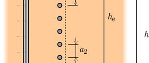
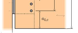
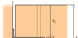
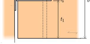
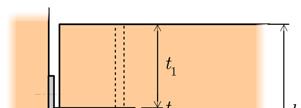
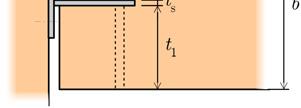
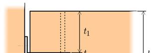
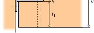
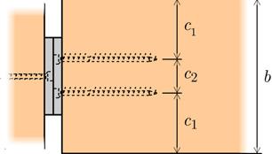
5 A.1 A.2 A.3 A.4 A.5 A.6 B.1 B.2 C.1 C.2 Figure 2.1. Geometries of the tested dowelled connections. D.1 Figure 2.2. Aluminiu m dovetail connection Table 2. Geometries of the tested dowelled connections. Connection b h d n d h e /h a 2 a 3,c a 4,t a 4,c s typology [mm 2 ] [mm] [ ] [mm] [mm] [mm] [mm] [mm] A.1, A A A A A B B C C D b and h are the width and the height of the cross section; d is the dowel diameter and n d is the number of dowels; h e is the distance from the most distant fastener to the loaded edge; a 2, a 3,c, a 4,t, and a 4,c are the dowel spacing, unloaded end distance, loaded edge distance, and unloaded edge distance, respectively; and s is the gap between the beam and the column.
 and because it was assumed that this part of the")

.")


![They were conducted in accordance with EN 26891:1991 [13], which prescribes a loading procedure based on the estimated load-carrying capacity F est of the connection: the](/docs-images/87/97357906/images/6-5.jpg "load is increased up to 0.4 F est, then reduced to 0.1 F est, and thereafter increased until failure. 3.")
; only connections B.2 and, possibly, A.")

6 a) b) Figure 3. Top view of the test set-up: a) tests at normal temperature; b) fire resistance tests. beam-side only tests were performed because most connections were estimated to fail on the beam-side (Table 3 and Figure 4a) and because it was assumed that this part of the connection would be most exposed to fire and therefore critical to fire resistance. The load applied by the loading plate, through the rods and hydraulic cylinders, was monitored using rod-end compression load cells. In the beam-side tests, another load cell was placed in the beam support opposite to the tested connection and the shear load in the connection was calculated by simple equilibrium (F connection = F rod - F support ). In the tests with the full beam-to-column connection, a load cell was positioned beneath the column and, therefore, the shear force going through the connection was directly measured. In addition to the load cells, displacement transducers were placed in the loading plate and in the connection area to assess the relative displacement between the timber member and the steel plate. The tests at normal temperature were performed at the laboratories of ETH Zurich, Switzerland. They were conducted in accordance with EN 26891:1991 [13], which prescribes a loading procedure based on the estimated load-carrying capacity F est of the connection: the load is increased up to 0.4 F est, then reduced to 0.1 F est, and thereafter increased until failure. 3.2 Results The estimated and experimental load-carrying capacities of the tested connections are presented in Table 3 and Figure 4. Most connections were expected to exhibit splitting failures (A.1-3,5-6, B.1, and C.1-2); only connections B.2 and, possibly, A.4, were expected to display ductile dowel failures. Regarding the estimated splitting capacities of the beam-side of the connections, it has to be mentioned that EN does not have specific rules for end-loaded members loaded perpendicularly to the grain, but only to mid-span loaded members. However, both the former German code for timber structures DIN 1052:2004 [6] and A. Leijten [14] (who developed the calculation model for mid-span loaded members in EN ) state that for connections at the end of a cantilever the splitting strength is half of the strength of mid-span loaded members. The results show that the beam-side load-carrying capacity is substantially underestimated by current design methods, even taking into account that R k,estimated are characteristic 5% percentile values and R mean,experimental are mean values. Also worth noticing is that the column-side load-carrying capacity seems to be significantly underestimated, as no failure in the column-side was observed in the full connection tests performed on typology A.5.
7 Table 3. Estimated and experimental load-carrying capacities of the connections tested at normal temperature. Connection Number R Type of test k,estimated [kn] typology of tests Beam-side Column-side R mean,experimental,20 C [kn] Beam-side (7%) - A.1 Full connection (beam-side failure) A A A.4 Beam-side 3 > (3%) - A.5 Full connection (beam-side failure) A.6 Beam-side (11%) - B.1 Beam-side (10%) - B.2 Beam-side (7%) - C.1 Beam-side (8%) - C.2 Beam-side (4%) - D.1 Full connection (acc. to the manufacturer) (column-side failure) Coefficient of variation between parentheses. a) b) Figure 4. Estimated load-carrying capacities of the tested dowelled connections: a) beam-side and column-side capacities; b) beam-side failure modes. 4 FIRE RESISTANCE TESTS The fire resistance tests were conducted in the small horizontal furnace of the Laboratory for Fire Testing at the Swiss Federal Laboratories for Materials Science and Technology (Empa), in Dübendorf, Switzerland. 4.1 Test set-up and procedure As previously described (Figure 3b), the test set-up used in the fire tests is very similar to one used in the tests at normal temperature. The same horizontal steel frame was positioned over the furnace, in such a way that the connection area was centred above the furnace s opening. In its plane, the connection was supported on a load-cell, placed at the bottom of the column-member (to measure directly the shear load in the connection, transferred as a compression force in the lower half of the column), and on a roller, located at the opposite end of the beam-member. The load was applied through a loading plate positioned on the top-side of the beam (which during the test it s on its side), connected by two steel rods to the
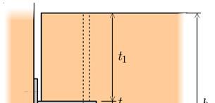
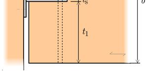
8 Figure 5. Schematic overview of the fire resistance tests set-up: a) horizontal furnace; b) steel frame over the furnace; c) connection specimen inside the frame; d) loading apparatus; e) outer cover. hydraulic cylinders. Since no equipment could be exposed to fire, only the displacements of the loading plates were measured, not the relative displacements between the members in the connection. The connection specimen was then partially enclosed by an insulated outer cover that allows the timber members to deform. The test set-up is presented in Figure 5. After the whole test set-up was ready, the connections were loaded up to the target load level (Table 1), which was approximately 30% of the load-carrying capacity at normal temperature, and that load was maintained throughout the fire test. Once the displacements stabilized, the burners were started and the connection area exposed to the standard ISO 834 [15] time-temperature curve. After failure, reached when the displacements in the beam increased ever rapidly and it no longer could sustain the applied load, the specimens were promptly removed from the furnace and cooled with water (Figure 6). Since the full connections tested at normal temperature failed on the beam-side (Table 3) and the column-side of the connections (header plate nailed to the column-member) was the same for every connection, except A.5 and D.1 (which were commercially available parts), to assure a beam side failure in the fire tests, the column-member was partially protected with insulation. This was mainly to focus the tests on the beam-side of the connections and to avoid that burning from the sides and the back of the column could promote a premature failure. a) b) c) d) Figure 6. Fire test: a) connection specimen in the steel frame over the furnace; b) outer cover enclosing a connection during a test; c) view of a connection inside the furnace; d) removal of the outer cover after a test.
9 4.2 Results and discussion The main results of the fire resistance tests are presented in Table 4. Two replicas of most connection typologies were tested and the corresponding results were consistent. All the dowelled connections (A, B, and C) exhibited fire resistances higher than 30 minutes and connections A.6 and C.2 reached 60 minutes, which is accordance with Lignum s documentation on the fire resistance of timber connections [8]. Regarding the influence of the gap between the beam and the column, it can be seen that an increase from 10 mm (A.1) to 20 mm (A.2) lead to an average reduction from 44 to minutes of fire resistance. On the other hand, a reduction of the gap from 10 mm (A.1) to 0 mm (A.3) led to an increase of the fire resistance of only 3-4 minutes. The larger 20 mm gap between the beam and the column induced failures in the column-side of the connection, unlike the 10 mm and 0 mm gaps for which failure occurred in the beam-side (embedment of the dowels followed by splitting of the beam). As charring from the sides was mostly prevented in the column-members, the heat damage to the column side came mostly from above and below the header plate, directly affecting the outermost nails in withdrawal and compression zone of the header plate, allowing it to rotate. The connection reinforced with self-drilling screws (A.4) exhibited a fire resistance 5 minutes lower than the corresponding unreinforced connection (A.1). The reinforcement with self-drilling screws is an effective and widespread way to deal with the brittle splitting failures of the unreinforced connections loaded perpendicularly to the grain. However, as observed in a previous experimental campaign performed by the authors on the fire resistance of tension connections reinforced with self-drilling screws [7], the reinforcement screws also conduct heat into the cross-section (Figure 8), which in some cases compromises the fire resistance. Table 4. Results of the fire resistance tests. Connection Load Fire resistance E fire t fi Typology Specimen [kn] [min.] A.1 A.1.F-1 a A.1.F A.2 A.2.F A.2.F A.3 A.3.F A.3.F A.4 A.4.F A.5 A.5.F A.6 A.6.F A.6.F B.1 B.1.F B.1.F B.2 B.2.F B.2.F C.1 C.1.F C.1.F C.2 C.2.F C.2.F D.1 D.1.F

 had gap of only 6 mm between the beam and the column (Figure 2.")
, although it failed on the beam-side at normal temperature.")


 Figure 8. Connections A.4 and A.5 after the fire tests.")
 and showed brittle splitting (B.")


.")
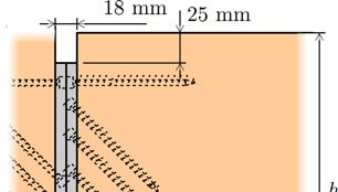
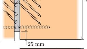
10 A.1 (10 mm gap) A.2 (20 mm gap) A.3 (0 mm gap) Figure 7. Influence of the gap between the beam and the column: connections A.1, A.2, and A.3 after the fire tests. The common commercially available concealed beam-hanger (A.5) had gap of only 6 mm between the beam and the column (Figure 2.1 and Table 2), but a much lower estimated load-carrying capacity of the column-side of the connection (Table 3 and Figure 4a), although it failed on the beam-side at normal temperature. This commercial connection exhibit a fire resistance 5 minutes lower than the custom A.1 connection and failed in the column-side, with a failure mode similar to that of the connections A.2. However, the load in connection A.5 during the fire test was about 40% of the load-carrying capacity of the beam-side at normal temperature, instead of the 30% in connections A.1-3. A.4 (reinforced) A.5 (commercial beam-hanger) Figure 8. Connections A.4 and A.5 after the fire tests. The influence of the failure mode can be analysed in the connections B.1 and B.2. These connections had smaller sized dowels (diameter of 8 mm) and showed brittle splitting (B.1) and ductile embedment/dowel failures (B.2) at normal temperature. In the fire tests, however, both typologies exhibited similar extensive embedment failures, followed by splitting. In fire, the smaller minimum dowel spacing perpendicular to the grain prescribed by EN (only 3 d, compared to 5 d parallel to the grain) leads to a premature failure when all the wood between the dowels is charred (Figure 9). Also the smaller minimum unloaded edge distances (connection B.2) perpendicular to the grain (only 3 d, compared to 7 d parallel to the grain) result in the complete charring of the wood surrounding the outermost dowels. Regardless of the failure mode at normal temperature, both connection typologies exhibited approximately the same fire resistance. B.1 B.2 Figure 9. Connections B.1 and B.2 after the fire tests.


![2 reached more than the estimated minimum 60 minutes of fire resistance [8].](/docs-images/87/97357906/images/11-4.jpg "Regarding connections A.")
 and compression zones and")
 was smaller than in connections A.")


11 Connections C.1 exhibited shear/splitting failures at normal temperature and the highest load-carrying capacities of the R30 connections (Table 3). In the fire tests, they reached approximately the same fire resistance as connections A.1. In fire, the dowels remained mostly straight and the wood surrounding the dowels closer to the unloaded edge charred completely. After failure, splitting cracks could be observed in the beam side. C.1 Figure 10. Connections C.1 after the fire tests. Connections A.6 and C.2 reached more than the estimated minimum 60 minutes of fire resistance [8]. Regarding connections A.6 (with 12 mm dowels), the long fire exposure charred the wood below and above the header steel plate nailed to the column, affecting the tension (nail withdrawal) and compression zones and allowing the steel plates to rotate (Figure 11, left). The dowels end distance in connections C.1 (8 mm dowels) was smaller than in connections A.6 and, consequently, so was the moment in the header plate. Therefore, the rotation of the header plate was negligible. On the other hand, the charred depth in the zone between the dowels and the end of the beam was significantly higher than elsewhere in the beam, due to additional heat coming from the burning column-member and transferred by the dowels into the cross-section. After the wood between the dowels charred, the load was mostly transferred through the last dowel and it ultimately bent (Figure 11, right). A.6 C.2 Figure 11. Connections A.6 and C.2 after the fire tests. Finally, the commercial aluminium dovetail connection D.1 also reached more than 30 minutes of fire resistance, failing in the connector itself after 36 minutes. This connection had a gap of 18 mm between the beam and the column (thickness of the connector), which is larger than the 10 mm of most of the other connections. D.1 Figure 12. Connection D.1 after the fire test.
12 5 CONCLUSIONS This paper presents the results of an extensive experimental campaign on the fire behaviour of beamto-column timber connections loaded perpendicular-to-the-grain. A special test set-up was developed and it was successfully used in both the tests at normal temperature and the fire tests. The results of the fire resistance tests show that the tested typologies of steel-to-timber dowelled connections reached more than 30 and even 60 minutes of fire resistance. However, aspects such as a wider gap between the beam and the column, reduced dowel spacing, and the presence of reinforcement with self-drilling screws all have a negative influence on the fire resistance. Even though the beam-side of these connections is apparently more exposed to fire, failures in column-side also occurred and, therefore, the fire resistance of these connections has to take into account these two parts. REFERENCES [1] EN :2004 Eurocode 5: Design of timber structures Part 1-1: General Structural fire design, European Committee for Standardization (CEN), Brussels, [2] J. König, M. Fontana, The performance of timber connections in fire Test results and rules of Eurocode 5, in: Proceedings of International RILEM Symposium Joints in Timber Structures, RILEM Publications, Stuttgart, Germany, 2001: pp [3] J. Norén, Load-bearing capacity of nailed joints exposed to fire, Fire and Materials. 20 (1996) [4] D. Dhima, Vérification expérimentale de la résistance au feu des assemblages d éléments en bois, Centre Technique Industriel de la Construction Métallique (CTICM), Saint-Rémy-lès-Chevreuse, France, [5] J. Kruppa, T. Lamadon, P. Racher, Fire resistance tests of timber connections, CTICM - Departement Incendie et Essais, Saint-Remy-Les-Chevreuse, France, [6] DIN 1052: Entwurf, Berechnung und Bemessung von Holzbauwerken. Allgemeine Bemessungsregeln und Bemessungsregeln für den Hochbau, Deutsches Institut für Normung (DIN), [7] P. Palma, A. Frangi, E. Hugi, P. Cachim, H. Cruz, Fire resistance tests on steel-to-timber dowelled connections reinforced with self-drilling screws, in: Proceedings of the 2nd Ibero-Latin-American Congress on Fire Safety 2nd CILASCI, Coimbra, Portugal, [8] A. Frangi, I. Brühwiler, J. Studhalter, R. Wiederkehr, Lignum-Dokumentation Brandschutz. 3.1 Feuerwiderstandsbemessung Bauteile und Verbindungen, Lignum Holzwirtschaft Schweiz, Zurich, [9] EN 1194:1999. Timber structures Glued laminated timber Strength classes and determination of characteristic values, European Committee for Standardization (CEN), Brussels, [10] EN :2004. Hot rolled products of structural steels - Technical delivery conditions for nonalloy structural steels, European Committee for Standardization (CEN), Brussels, [11] EN :2005. Eurocode 3: Design of steel structures Part 1-8: Design of joints, European Committee for Standardization (CEN), Brussels, [12] EN 10346:2009. Continuously hot-dip coated steel flat products. Technical delivery conditions, European Committee for Standardization (CEN), Brussels, [13] EN 26891:1991. Joints made with mechanical fasteners General principles for the determination of strength and deformation characteristics, European Committee for Standardization (CEN), Brussels, [14] A. Leijten, Splitting strength of beams loaded by connections - Model comparison, in: Proceedings of the CIB-W18 Meeting 35, CIB, Kyoto, Japan, [15] ISO 834-1:1999. Fire-resistance tests. Elements of building construction. Part 1: General requirements, International Organization for Standardization (ISO), 1999.
Mechanical behavior of fiberglass reinforced timber joints
 Mechanical behavior of fiberglass reinforced timber joints Chen, Chi-Jen 1 ABSTRACT The objective of this research is to investigate the mechanical performance of dowel-type timber joints reinforced by
SCREWS WITH CONTINUOUS THREADS IN TIMBER CONNECTIONS
 SCREWS WITH CONTINUOUS THREADS IN TIMBER CONNECTIONS Prof. Dr.-Ing. H. J. Blaß, Dipl.-Ing. I. Bejtka Universität Karlsruhe (TH), Germany Abstract Screws, bolts and dowels loaded perpendicular to the fastener
Moment-Resisting Connections In Laminated Veneer Lumber (LVL) Frames
 Frames") Moment-Resisting Connections In Laminated Veneer Lumber (LVL) Frames Andy van Houtte Product Engineer-LVL Nelson Pine Industries Nelson, NZ Andy Buchanan Professor of Civil Engineering Peter Moss Associate
Moment-Resisting Connections In Laminated Veneer Lumber (LVL) Frames Andy van Houtte Product Engineer-LVL Nelson Pine Industries Nelson, NZ Andy Buchanan Professor of Civil Engineering Peter Moss Associate
Dowel connections in laminated strand lumber
 Dowel connections in laminated strand lumber Cranswick, Chad J. 1, M c Gregor, Stuart I. 2 ABSTRACT Laminated strand lumber (LSL) is a relatively new structural composite lumber. As such, very limited
Load carrying capacity of dowelled connections
 Load carrying capacity of dowelled connections H.J. Blass, Karlsruhe Institute of Technology F. Colling, Augsburg University of Applied Sciences Keywords: Dowel, yield moment, connection 1 Introduction
Anti-check bolts as means of repair for damaged split ring connections
 Anti-check bolts as means of repair for damaged split ring connections Quenneville, J.H.P. 1 and Mohammad, M. 2 ABSTRACT There are numerous large span timber hangars dating back to the Second World War.
Investigations on the Effectiveness of Self-tapping Screws in Reinforcing Bolted Timber Connections
 Investigations on the Effectiveness of Self-tapping Screws in Reinforcing Bolted Timber Connections Mohammad Mohammad Group Leader, Building Systems Forintek Canada Corp, Eastern Division Quebec, Canada
BauBuche Fasteners and connections
 BauBuche Fasteners and connections Beech laminated veneer lumber Chapter under revision 05 BauBuche Fasteners and connections 05 04-18 - EN Sheet 1 / 10 Fasteners and connections Sheet CONTENTS 2 3 4 9
Dowel type joints Influence of moisture changes and dowel surface smoothness. Erik Serrano and Johan Sjödin, Växjö University, Sweden
 Dowel type joints Influence of moisture changes and dowel surface smoothness Erik Serrano and Johan Sjödin, Växjö University, Sweden Background and introduction With the increased use of glulam in large-span
Dowel-type fasteners. Timber Connections. Academic resources. Introduction. Deferent types of dowel-type fasteners. Version 1
 Academic resources Timber Connections Dowel-type fasteners Version 1 This unit covers the following topics: Deferent types of dowel-type fasteners Introduction There are four criteria designers should
Glued laminated timber beams repair.
 Glued laminated timber beams repair. Master s Degree Extended Abstract Ricardo Cardoso Henriques da Silva Keywords: glulam, delamination, self-tapping screw, plywood, repair November 2014 1. INTRODUCTION
EVALUATION OF SCREWS USED IN LAMINATED VENEER LUMBER ROCKING CONNECTIONS
 EVALUATION OF SCREWS USED IN LAMINATED VENEER LUMBER ROCKING CONNECTIONS D. M. Carradine, M. P. Newcombe and A. H. Buchanan Dept. of Civil and Natural Resources Engineering, University of Canterbury, Private
Pull-compression tests on glued-in metric thread rods parallel to grain in different timber species and laminated veneer lumber
 COST FP1004 15-17 April 2015 Lisbon, Portugal Pull-compression tests on glued-in metric thread rods parallel to grain in different timber species and laminated veneer lumber Frank Hunger 1, Mislav Stepinac
The predictive model for strength of inclined screws as shear connection in timber-concrete composite floor
 The predictive model for strength of inclined screws as shear connection in timber-concrete composite floor F. Moshiri, C. Gerber, H.R. Valipour, R. Shrestha & K.I. Crews Centre for built infrastructure,
NON-LINEAR CONNECTION MODELS IN TIMBER ENGINEERING
 NON-LINEAR CONNECTION MODELS IN TIMBER ENGINEERING Michael Dorn 1, Thomas K. Bader 2 ABSTRACT: In this contribution, a numerical model for connections in engineered timber structures, using specially designed
Bolts and Set Screws Are they interchangeable?
 1903191HA Bolts and Set Screws Are they interchangeable? Prof. Saman Fernando Centre for Sustainable Infrastructure SUT Introduction: This technical note discusses the definitions, standards and variations
Glulam Connection Details
 T E C H N I C A L N O T E Glulam Connection Details Note: This version is superseded by a more current edition. Check the current edition for updated design and application recommendations. ENGINEERED
Fire behavior of primary beam- secondary beam connections in timber structures
 Short report for the research project Fire behavior of primary beam- secondary beam connections in timber structures Research Institution: Technische Universität München Lehrstuhl für Holzbau und Baukonstruktion
Ductility of large-scale dowelled CLT connections under monotonic and cyclic loading
 Ductility of large-scale dowelled CLT connections under monotonic and cyclic loading Lisa-Mareike Ottenhaus 1, Minghao Li 2, Tobias Smith 3 1. PhD candidate, Department of Civil and Natural Resources Engineering,
Lawrence A. Soltis, M. and Robert J. Ross, M. 1
 REPAIR OF WHITE OAK GLUED-LAMINATED BEAMS Lawrence A. Soltis, M. and Robert J. Ross, M. 1 Abstract Connections between steel side plates and white oak glued-laminated beams subjected to tension perpendicular-to-grain
PRO LIGNO Vol. 11 N pp
 FINITE ELEMENT SIMULATION OF NAILED GLULAM TIMBER JOINTS Mats EKEVAD Luleå University of Technology Division of Wood Science and Engineering SE-931 87 Skellefteå, Sweden Tel: +46 910 585377; E-mail: mats.ekevad@ltu.se
Title. CitationJournal of Wood Science, 58(4): Issue Date Doc URL. Rights. Type. File Information.
: Issue Date Doc URL. Rights. Type. File Information.") Title Effective lateral resistance of timber-plywood-timbe Author(s)Wanyama, Okumu Gordon; Sawata, Kei; Hirai, Takuro; K CitationJournal of Wood Science, 58(4): 315-321 Issue Date 2012-08 Doc URL http://hdl.handle.net/2115/50078
Title Effective lateral resistance of timber-plywood-timbe Author(s)Wanyama, Okumu Gordon; Sawata, Kei; Hirai, Takuro; K CitationJournal of Wood Science, 58(4): 315-321 Issue Date 2012-08 Doc URL http://hdl.handle.net/2115/50078
Available online at ScienceDirect. Procedia Engineering 114 (2015 )
") Available online at www.sciencedirect.com ScienceDirect Procedia Engineering 114 (2015 ) 240 247 1st International Conference on Structural Integrity Dowel type joints of round timber exposed to static
Available online at www.sciencedirect.com ScienceDirect Procedia Engineering 114 (2015 ) 240 247 1st International Conference on Structural Integrity Dowel type joints of round timber exposed to static
eb^sv=qfj_bo UNIVERSITY OF WISCONSIN - STOUT COLLEGE OF SCIENCE TECHNOLOGY ENGINEERING & MATHEMATICS Architectural Technology AEC 233
 eb^sv=qfj_bo UNIVERSITY OF WISCONSIN - STOUT COLLEGE OF SCIENCE TECHNOLOGY ENGINEERING & MATHEMATICS Architectural Technology AEC 233 Dr. Jason E. Charalambides fkqolar`qflk Heavy timber construction consists
STRUCTURAL TIMBER DESIGN
 STRUCTURAL TIMBER DESIGN to Eurocode 5 2nd Edition Jack Porteous BSc, MSc, DIC, PhD, CEng, MIStructE, FICE Director lack Porteous Consultancy and Abdy Kernlani BSc, MSc, PhD, CEng, FIStructE, FIWSc Professor
Cyclic Response of Dowel Connections in Precast Structures
 Cyclic Response of Dowel Connections in Precast Structures M. Fischinger, B. Zoubek, M. Kramar, T. Isaković University of Ljubljana, Faculty of Civil and Geodetic Engineering, Slovenia SUMMARY: Precast
Connections in CLT Assemblies
 Creating forest sector solutions www.fpinnovations.ca Connections in CLT Assemblies Cross Laminated Timber Symposium Vancouver, BC February 8-9, 2011 M. Mohammad Building Systems Wood Products Division
Experimental and numerical study of nailed laminated timber elements for in plane and transverse loading
 Experimental and numerical study of nailed laminated timber elements for in plane and transverse loading Haller, Peer 1 SUMMARY Nailed laminated timber elements are used in housing construction for floor,
Hanger bolts and solar fasteners in sandwich panels
 Hanger bolts and solar fasteners in sandwich panels Helmut Krüger 1, Thomas Ummenhofer 2, Daniel C. Ruff 3 Abstract For the energetic use of sunlit roofs, photovoltaic and solar thermal elements are mounted
Module 10 : Improvement of rock mass responses. Content
 IMPROVEMENT OF ROCK MASS RESPONSES Content 10.1 INTRODUCTION 10.2 ROCK REINFORCEMENT Rock bolts, dowels and anchors 10.3 ROCK BOLTING MECHANICS Suspension theory Beam building theory Keying theory 10.4
A Shell construction
 A Shell construction A 4/2012 Content 1 BASE AND WALL ANCHORING 1.1 Base with mortar bed 1.2 Base with sill plate 1.3 Base with raised sill plate 1.4 Concrete base (mortar bed) 1.5 Concrete base (sill
Keywords: Bracing bracket connection, local deformation, selective pallet racks, shear stiffness, spine bracings.
 Send Orders for Reprints to reprints@benthamscience.ae The Open Construction and Building Technology Journal, 2015, 9, 1-6 1 Open Access Investigation of Shear Stiffness of Spine Bracing Systems in Selective
Splitting strength of beams loaded perpendicular to grain by connections, a fracture mechanical approach
 Splitting strength of beams loaded perpendicular to grain by connections, a fracture mechanical approach Ad Leijten Civil Eng. PhD, Senior Researcr University of Techn. Delft Delft, T Netrlands A.Leijten@citg.tudelft.nl
Cast-in Ferrule Connections Load/Displacement Characteristics in Shear
 Cast-in Ferrule Connections Load/Displacement Characteristics in Shear Ian Ferrier 1 and Andrew Barraclough 2 1 Product Manager - Connections, ITW Construction Systems ANZ. 2 Research and Development Manager,
TEST SERIES TO EVALUATE THE STRUCTURAL BEHAVIOUR OF ISOBOARD OVER RAFTER SYSTEM
 TEST SERIES TO EVALUATE THE STRUCTURAL BEHAVIOUR OF ISOBOARD OVER RAFTER SYSTEM J A Wium Institute of Structural Engineering 19 November 2007 ISI2007-3 TEST SERIES TO EVALUATE THE STRUCTURAL BEHAVIOUR
ALUMIDI. Concealed beam hanger with and without holes Aluminum alloy tridimensional perforated plate ALUMIDI - 01 CERTIFIED STEEL-ALUMINUM
 ALUMIDI Concealed beam hanger with and without holes Aluminum alloy tridimensional perforated plate CERTIFIED Available with and without holes. The 2200 mm model is also certified FIELD OF USE Timber-to-Timber
Verbindungselemente Engel GmbH Weltestraße Weingarten DEUTSCHLAND. Manufacturing plant 74437, , ,
 European Technical Assessment ETA-13/0536 of 20 February 2018 - Original version in German language General Part Technical Assessment Body issuing the European Technical Assessment: Trade name of the construction
Instruction Manual for installing
 Instruction Manual for installing Preloaded (HSFG) Bolting with TurnaSure DIRECT TENSION INDICATORS CE Marked EN 14399-9 TurnaSure LLC TABLE OF CONTENTS Introduction... 1 Theory of Preloaded Bolting Assemblies...
ISO INTERNATIONAL STANDARD. Fasteners Torque/clamp force testing. Éléments de fixation Essais couple/tension. First edition
 Provläsningsexemplar / Preview INTERNATIONAL STANDARD ISO 16047 First edition 2005-02-01 Fasteners Torque/clamp force testing Éléments de fixation Essais couple/tension Reference number ISO 16047:2005(E)
Connection and performance of two-way CLT plates
 Connection and performance of two-way CLT plates by Chao (Tom) Zhang George Lee Dr. Frank Lam Prepared for Forestry Innovation Investment 1130 W Pender St, Vancouver BC V6E 4A4 Timber Engineering and Applied
TECHNICAL MANUAL. TERADOWEL and ULTRADOWEL. Reliable Dowel System for Floor Joints
 TECHNICAL MANUAL TERADOWEL and ULTRADOWEL Reliable Dowel System for Floor Joints Version: PEIKKO GROUP 11/2018 TERADOWEL and ULTRADOWEL Reliable Dowel System for Floor Joints Dowels manufactured from high
LOAD CARRYING CAPACITY OF METAL DOWEL TYPE CONNECTIONS OF TIMBER STRUCTURES
 Vol. 10, Issue /014, 51-60 DOI: 10.478/cee-014-0011 LOAD CARRYING CAPACITY OF METAL DOWEL TYPE CONNECTIONS OF TIMBER STRUCTURES Jozef GOCÁL 1,* 1 Department of Structures and Bridges, Faculty of Civil
ISO INTERNATIONAL STANDARD. Timber structures Dowel-type fasteners Part 1: Determination of yield moment
 INTERNATIONAL STANDARD ISO 10984-1 First edition 2009-08-15 Timber structures Dowel-type fasteners Part 1: Determination of yield moment Structures en bois Éléments de fixation de type cheville Partie
European Technical Assessment ETA-13/0029 of 11/07/2017
 ETA-Danmark A/S Göteborg Plads 1 DK-2150 Nordhavn Tel. +45 72 24 59 00 Fax +45 72 24 59 04 Internet www.etadanmark.dk Authorised and notified according to Article 29 of the Regulation (EU) No 305/2011
GLOSSARY OF TERMS SECTION 8
 GLOSSARY OF TERMS SECTION 8 Anchor Bolt Angle Base Plate Bay Blocking CCB Centerline Chord Cladding Clip Closure Strip An A-307 steel bolt embedded in the concrete footing to anchor the base plate of the
Design of structural connections for precast concrete buildings
 BE2008 Encontro Nacional Betão Estrutural 2008 Guimarães 5, 6, 7 de Novembro de 2008 Design of structural connections for precast concrete buildings Björn Engström 1 ABSTRACT A proper design of structural
Instruction Manual for installing
 Instruction Manual for installing Preloaded (HSFG) Bolting with TurnaSure DIRECT TENSION INDICATORS TurnaSure LLC TABLE OF CONTENTS Introduction... 1 Theory of Preloaded Bolting Assemblies... 2 Tightening
Comparison of behaviour of laterally loaded round and squared timber bolted joints
 Focussed on Modelling in Mechanics Comparison of behaviour of laterally loaded round and squared timber bolted joints Antonín Lokaj, Kristýna Klajmonová VŠB echnical University of Ostrava, Faculty of Civil
Prediction of Reinforcement Effect by Screw on Triangular Embedment Perpendicular to the Grain with Variation of Screw Locations
 Open Journal of Civil Engineering,,, 67-73 http://dx.doi.org/.436/ojce..3 Published Online September (http://www.scirp.org/journal/ojce) of Reinforcement Effect by Screw on Triangular Embedment Perpendicular
MONOTONIC TESTS OF STRUCTURAL CARPENTRY JOINTS
 MONOTONIC TESTS OF STRUCTURAL CARPENTRY JOINTS Pedro Palma 1, João Ferreira 2, Helena Cruz 3 ABSTRACT: An experimental campaign on traditional diagonal front notched timber joints was carried out in order
Korean standards of visual grading and establishing allowable properties of softwood structural lumber
 Korean standards of visual grading and establishing allowable properties of softwood structural lumber Park, Moon-Jae 1, Shim, Kug-Bo 1 ABSTRACT Korean standards related to wood products such as "Sizes
Experimental study on the fire performance of straight-line dovetail joints
 Journal of Wood Science (218) 64:193 28 https://doi.org/1.17/s186-18-1694-z ORIGINAL ARTICLE Experimental study on the fire performance of straight-line dovetail joints Jin Zhang 1 Yixiang Xu 2 Fang Mei
The Behaviour Of Round Timber Sections Notched Over The Support On The Tension Face. Justin Dewey
 The Behaviour Of Round Timber Sections Notched Over The Support On The Tension Face Justin Dewey Need for research In Queensland there are approximately 400 timber bridges still in use. Very little research
Connection Philosophy. p NDS Chapter-by-chapter description Changes from previous editions Examples. Part 1: Member Design Webinar.
 Outline ASD and LRFD with the 2005 NDS Part 2 Connection Design Presented by: John Buddy Showalter, P.E. Vice President, Technology Transfer Connection philosophy p NDS Chapter-by-chapter description Changes
Experimental Evaluation of Metal Composite Multi Bolt Radial Joint on Laminate Level, under uni Axial Tensile Loading
 RESEARCH ARTICLE OPEN ACCESS Experimental Evaluation of Metal Composite Multi Bolt Radial Joint on Laminate Level, under uni Axial Tensile Loading C Sharada Prabhakar *, P Rameshbabu** *Scientist, Advanced
Butt Two pieces of wood meeting with flat sides adjoining usually at right angles. Some type of connector is needed to prevent movement.
 Wood Connections There are basically five different types of connectors: Interlocking (carpentry joints), Dowel, Metal Connectors, Special Formed Connectors and Adhesives. I Interlocking (Carpentry Joints)
American Institute of Timber Construction 7012 South Revere Parkway Suite 140 Centennial, CO Phone: 303/ Fax: 303/
 American Institute of Timber Construction 7012 South Revere Parkway Suite 140 Centennial, CO 80112 Phone: 303/792-9559 Fax: 303/792-0669 404.1. SCOPE STANDARD FOR RADIALLY REINFORCING CURVED GLUED LAMINATED
Z January 2017
 Certified True Translation 11 January 2017 I 36-1.14.4-100/16 Z-14.4-776 11 January 2017 30 September 2021 SFS intec GmbH In den Schwarzwiesen 2 61440 Oberursel, Germany Zulassungsnummer = Approval Number
4) Verify that the size of the supporting member can accommodate the connector s specified fasteners.
 Verify that the size of the supporting member can accommodate the connector s specified fasteners.") DESIGN NOTES 1) Allowable loads for more than one direction for a single connection cannot be added together. A design load which can be divided into components in the directions given must be evaluated
DESIGN NOTES 1) Allowable loads for more than one direction for a single connection cannot be added together. A design load which can be divided into components in the directions given must be evaluated
Moment resistance of bolted timber connections with perpendicular to grain reinforcements
 Moment resistance of bolted timber connections with perpendicular to grain reinforcements Frank LAM Ph.D. P.Eng., Professor The University of British Columbia Vancouver, BC, Canada Michael SchulteWREDE
Mira Dedijer 1, Stéphane Roche 2, Yves Weinand 3 1 INTRODUCTION 123. θ rotations.
 SHEAR RESISTANCE AND FAILURE MODES OF EDGEWISE MULTIPLE TAB-AND-SLOT JOINT (MTSJ) CONNECTION WITH DOVETAIL DESIGN FOR THIN LVL SPRUCE PLYWOOD KERTO-Q PANELS Mira Dedijer, Stéphane Roche, Yves Weinand ABSTRACT:
Development of Wooden Portal Frame Structures with Improved Columns
 Development of Wooden Portal Frame Structures with Improved Columns by Dr. Masahiro Noguchi Post Doctoral Fellow Tokyo Institute of Technology, Yokohama, Kanagawa, Japan Prof. dr. Kohei Komatsu Professor
Use of grooved clamping plate to increase strength of bolted moment connection on cold formed steel structures
 IOP Conference Series: Materials Science and Engineering PAPER OPEN ACCESS Use of grooved clamping plate to increase strength of bolted moment connection on cold formed steel structures To cite this article:
ENGINEERED BUILDING PRODUCTS. SplitHanger. mitek.com.au
 ENGINEERED BUILDING PRODUCTS SplitHanger mitek.com.au S p l i t H a n g e r SUITABLE FOR VARIOUS WIDTHS OF TIMBER BEAM APPLICATION: SplitHangers are versatile hangers that provide a heavy duty connection
Factors Affecting Pre-Tension and Load Carrying Capacity in Rockbolts - A Review of Fastener Design
 University of Wollongong Research Online Coal Operators' Conference Faculty of Engineering and Information Sciences 2018 Factors Affecting Pre-Tension and Load Carrying Capacity in Rockbolts - A Review
Tension Perpendicular to Grain Strength of Wood, Laminated Veneer Lumber, and a Wood Plastic Composite.
 Tension Perpendicular to Grain Strength of Wood, Laminated Veneer Lumber, and a Wood Plastic Composite. Tracy Hummer, Research Assistant J. Daniel Dolan, Professor Michael Wolcott, Professor Wood Materials
THE ENGINEERED WOOD ASSOCIATION
 D A T A F I L E APA Performance Rated Rim Boards A rim board is the wood component that fills the space between the sill plate and bottom plate of a wall or, in second floor construction, between the top
HECO-TOPIX -CombiConnect HECO-TOPIX -Therm HCS-Calculation software
 HECO-TOPIX -CombiConnect HECO-TOPIX -Therm HCS-Calculation software THE WOOD SCREW FOR THE PROFESSIONAL The HECO-Calculation software (HCS) and HECO-TOPIX Woodscrews for easy estimation and safe assembling
Fasteners Torque/clamp force testing (ISO 16047:2005)
") SVENSK STANDARD SS- Fastställd 2005-02-18 Utgåva 1 Fästelement Provning av moment/kraftutbyte (ISO 16047:2005) Fasteners Torque/clamp force testing (ISO 16047:2005) ICS 21.060.01 Språk: engelska Publicerad:
SVENSK STANDARD SS- Fastställd 2005-02-18 Utgåva 1 Fästelement Provning av moment/kraftutbyte (ISO 16047:2005) Fasteners Torque/clamp force testing (ISO 16047:2005) ICS 21.060.01 Språk: engelska Publicerad:
Timber Rivet Connections Design Process for a Hanger Connection
 Timber Rivet Connections Design Process for a Hanger Connection RobertJ.Taylor,PhD,P.Eng.,Assoc.AIAand DavidM.Moses,PhD,P.Eng.,P.E.,LEED AP Introduction Timber rivet connections have been used successfully
Simplified analysis of timber rivet connections
 Simplified analysis of timber rivet connections Stahl, Douglas C., 1 Begel, Marshall, 2 and Wolfe, Ronald W. 3 ABSTRACT Timber rivets, fasteners for glulam and heavy timber construction, have been used
European Technical Approval ETA-10/0413
 ETA-Danmark A/S Kollegievej 6 DK-2920 Charlottenlund Tel. +45 72 24 59 00 Fax +45 72 24 59 04 Internet www.etadanmark.dk Authorised and notified according to Article 10 of the Council Directive 89/106/EEC
SECTION METAL FABRICATIONS
 SECTION 05100 PART 1 - GENERAL 1.01 DESCRIPTION A. Section includes specifications for metal fabrications, including minimum requirements for fabricator, and galvanizing. 1.02 REFERENCE STANDARDS A. ASTM
Subject of approval: fischer concrete screw ULTRACUT FBS II for the temporary fastening of building site equipment
 Date: Reference: 13 July 2016 I 25-1.21.8-49/15 Approval number: Validity Z-21.8-2049 from: 13 July 2016 Applicant: fischerwerke GmbH & Co. KG Klaus-Fischer-Straße 1 72178 Waldachtal to: 13 July 2021 Subject
AMTS STANDARD WORKSHOP PRACTICE. Bond Design
 AMTS STANDARD WORKSHOP PRACTICE Reference Number: AMTS_SWP_0027_2008 Date: December 2008 Version: A 1 Contents 1 Technical Terms...3 2 Scope...3 3 Primary References...3 4 Basic...3 4.1 Typical joint types...4
ISO 7438 INTERNATIONAL STANDARD. Metallic materials Bend test. Matériaux métalliques Essai de pliage. Second edition
 INTERNATIONAL STANDARD ISO 7438 Second edition 2005-06-15 Metallic materials Bend test Matériaux métalliques Essai de pliage Reference number ISO 7438:2005(E) ISO 2005 PDF disclaimer This PDF file may
APA Performance Rated Rim Boards
 D a t a F i l e APA Performance Rated Rim Boards A Rim Board is the wood component that fills the space between the sill plate and bottom plate of a wall or, in second floor construction, between the top
RlGIDITY AND STRENGTH OF WALL FRAMES BRACED WlTH METAL STRAPPING
 RlGIDITY AND STRENGTH OF WALL FRAMES BRACED WlTH METAL STRAPPING information Reviewed and Reaffirmed March 1955 No. R1603 UNITED STATES DEPARTMENT OF AGRICULTURE FOREST SERVICE FOREST PRODUCTS LABORATORY
A STUDY ON PATTERN DAMAGE OF FINGER JOINTS IN BAMBOO LAMINATED BEAMS
 A STUDY ON PATTERN DAMAGE OF FINGER JOINTS IN BAMBOO LAMINATED BEAMS Agus Rivani * * Abstract The aim of this study was to know the pattern damage of finger joints in bamboo laminated beams. The dimension
EXPERIMENTAL INVESTIGATION OF FATIGUE BEHAVIOUR IN COMPOSITE BOLTED JOINTS
 EXPERIMENTAL INVESTIGATION OF FATIGUE BEHAVIOUR IN COMPOSITE BOLTED JOINTS Roman Starikov 1 and Joakim Schön 2 1 Department of Aeronautics, Royal Institute of Technology SE-1 44 Stockholm, Sweden 2 Structures
CINEMATIC VISUALIZATION OF FAILURE MECHANISMS IN TIMBER STRUCTURES
 CINEMATIC VISUALIZATION OF FAILURE MECHANISMS IN TIMBER STRUCTURES Philipp Dietsch 1, Simon Schmid 2, Michael Merk 3, Stefan Winter 4 ABSTRACT: The objective of the project presented was to visualize typical
Load-carrying capacity of timber frame diaphragms with unidirectional support
 Load-carrying capacity of timber frame diaphragms with unidirectional support Jørgen Munch-Andersen, Danish Timber Information, 2012-06-26 Introduction The rules for determining the load-carrying capacity
Selection Guide for Flat Thermally Toughened Soda Lime Silicate Safety Glass
 Selection Guide for Flat Thermally Toughened Soda Lime Silicate Safety Glass February 2016 Administer by PO Box 7861, Halfway House, 1685 ASSOCIATION OF ARCHITECTURAL ALUMINIUM MANUFACTURERS OF SOUTH AFRICA
Effect of Vertical Load under Cyclic Lateral Load Test for Evaluating Sugi CLT Wall Panel
 Effect of Vertical Load under Cyclic Lateral Load Test for Evaluating Sugi CLT Wall Panel Minoru OKABE 1, Motoi YASUMURA 2, Kenji KOBAYASHI 3, Takeshi HARAMIISHI 4, Yo NAKASHIMA 5, Kazuhiko FUJITA ABSTRACT:
Statement for nail plate LL13 Combi
 STATEMENT NO VTT-S-0369-17 1 (5) Request by Order Contact person Ristek Oy Askonkatu 11 FI-15110 Lahti 15.3.017 Kimmo Köntti VTT Expert Services Ltd Ari Kevarinmäki P.O. Box 1001, FI-0044 VTT Tel. +358
Connection Design Examples
 Connection Design Examples Using the 2015 NDS (DES345) Lori Koch, P.E. Manager, Educational Outreach American Wood Council Adam Robertson, M.A.Sc., P.Eng. Manager, Codes and Standards Canadian Wood Council
DOWEL ACTION OF TITANIUM BARS CONNECTING MARBLE FRAGMENTS AT DIFFERENT ANGLES
 13 th International Brick and Block Masonry Conference Amsterdam, July 4-7, 2004 DOWEL ACTION OF TITANIUM BARS CONNECTING MARBLE FRAGMENTS AT DIFFERENT ANGLES E.Vintzileou 1, E.-E.Toumbakari 2 Abstract
Erstantie 2, FIN Villähde Tel , Fax
 www.anstar.eu 2 www.anstar.eu 3 CONTENTS Page 1 PRODUCT DESCRIPTION...4 2 MATERIALS AND STRUCTURE...4 2.1 PRODUCT RANGE...4 2.2 MATERIALS...4 2.3 MANUFACTURING...4 2.4 MANUFACTURING TOLERANCES...4 2.5
Load Tables, Technical Data and Installation Instructions
 W22. W22. W22. W22. W22 W22.. Simpson Strong-Tie Fastening Systems Structural Wood-to-Wood Connections Including Ledgers Designed to provide an easy-to-install, high-strength alternative to through-bolting
COOLING TECHNOLOGY INSTITUTE AN INVESTIGATION OF PIN BEARING
 PAPER NO: CATEGORY: TP1-24 MATERIALS COOLING TECHNOLOGY INSTITUTE AN INVESTIGATION OF PIN BEARING AN INVESTIGATION OF PIN BEARING STRENGTH ON COMPOSITE MATERIALS DUSTIN L. TROUTMAN JEREMEY D. MOSTOLLER
3.1 General Provisions
 WOOD FRAME CONSTRUCTION MANUAL 107 3.1 General Provisions 3.1.1 Prescriptive Requirements The provisions of this Chapter establish a specific set of resistance requirements for buildings meeting the scope
Proposal for new standard. Determination of interface friction between painted parts. Orientation. p. 1 (15) Draft1, Revised
 Draft1, Revised") p. 1 (15) Draft1, Revised 2018-03-29 Proposal for new standard Determination of interface friction between painted parts. Orientation This standard specifies the method and conditions to evaluate interface
p. 1 (15) Draft1, Revised 2018-03-29 Proposal for new standard Determination of interface friction between painted parts. Orientation This standard specifies the method and conditions to evaluate interface
WITHDRAWAL AND LATERAL STRENGTH OF THREADED NAILS
 238 WITHDRAWAL AND LATERAL STRENGTH OF THREADED NAILS Douglas R. Rammer, Donald A. Bender, and David G. Pollock An experimental study on the performance of threaded nails was conducted to understand and
ISO INTERNATIONAL STANDARD. Panneaux à base de bois Détermination du module d'élasticité en flexion et de la résistance à la flexion
 INTERNATIONAL STANDARD ISO 16978 First edition 2003-07-01 Wood-based panels Determination of modulus of elasticity in bending and of bending strength Panneaux à base de bois Détermination du module d'élasticité
European Technical Assessment. ETA-15/0667 of Member of. General part
 INSTITU Schenkenstrasse 4 T +43 1 533 65 50 1010 Vienna Ι Austria F +43 1 533 64 23 www.oib.or.at Ι mail@oib.or.at Designated according to Article 29 of Regulation (EU) No 305/2011 Member of www.eota.eu
Connection Solutions for Wood-frame Structures. Copyright Materials. Learning Objectives
 Connection Solutions for Wood-frame Structures Presented by: John Buddy Showalter, P.E. Vice President, Technology Transfer The Wood Products Council is a Registered Provider with. Credit(s) earned on
GLUED SOLID TIMBER DUO/TRIO
 GLUED SOLID TIMBER DUO/TRIO THE DIMENSIONALLY STABLE AESTHETE. 01 AT A GLANCE AREAS OF APPLICATION Single and multiple family houses Multi-storey residential buildings Visual application with the highest
Tech Guide. Screw Anchor Performance Why use a screw anchor? Ease in installation
 Why use a screw anchor? Screw anchors are used in medium duty applications that normally require faster installation time, close concrete edge distance, close anchor spacing and removability of anchor.
European Technical Assessment. ETA-16/0902 of 17 March English translation prepared by DIBt - Original version in German language.
 European Technical Assessment ETA-16/0902 of 17 March 2017 - Original version in German language General Part Technical Assessment Body issuing the European Technical Assessment: Trade name of the construction
STRUCTURAL FINGER JOINTED SOLID TIMBER
 STRUCTURAL FINGER JOINTED SOLID TIMBER THE BEAM WITH THE CHARACTER OF SOLID TIMBER. 01 AT A GLANCE AREAS OF APPLICATION Single and multiple family houses Multi-storey residential buildings Industrial and