PROCEDURE FOR DESIGN OF GLUED-LAMINATED
|
|
|
- Piers Greene
- 5 years ago
- Views:
Transcription


1 PROCEDURE FOR DESIGN OF GLUED-LAMINATED ORTHOTROPIC BRIDGE DECKS U.S.D.A. FOREST SERVICE RESEARCH PAPER FPL U.S. Department of Agriculture Forest Service Forest Products Laboratory Madison, Wis
2 ABSTRACT The most recent improvement in timber bridge design is the vertically glued-laminated panel deck, with the panels placed in a transverse direction to the stringers. Experimental evaluations showed its performance to be superior to that of the conventional nailed-laminated deck. Design methods which consider the glued-laminated deck as an orthotropic plate accurately predict its behavior, Since a laminated bridge deck is constructed from many relatively narrow panels, it is necessary to install connectors which allow the deck to act as a continuous plate. Eight different connector systems were evaluated and steel dowels are best suited for the purpose. Design criteria for dowel connectors, based on the theory of a beam supported on an elastic wood foundation, were developed. The problem of dimensional stability was investigated by observing the behavior of glued-laminated panels at a long term exposure site, and by observing bridges that have been in service for several years. It was found that creosote treatment greatly retards changes in moisture content and associated dimensional changes. The design procedures for glued-laminated transverse decks and steel dowel connectors are presented as a set of easy-to-use graphs and tables. These should be of immediate use for designers of timber bridges. -i-
3 PROCEDURE FOR DESIGN OF GLUED-LAMINATED ORTHOTROPIC BRIDGE DECKS By WILLIAM J. McCUTCHEON, Engineer and ROGER L. TUOMI, Engineer Forest Products Laboratory 1 Forest Service U.S. Department of Agriculture INTRODUCTlON Timber bridges have a long record of service in the secondary road systems of this country. In the National Forests alone approximately 7,500 bridges are in use with more being built each year, and the railroads have over 1,500 miles of timber bridges and trestles in service (3 ). 2 The most common type of timber bridge, by far, has longitudinal stringers with transverse timber decking. Typically, the decking consists of nailed-laminated 2-inch lumber where the material is throughnailed together and toenailed to the stringers. This system has a long record of use. Because of the close spacings of solid sawn stringers, the deck deflections were minimal and performance was adequate. With the advent of glued-laminated stringers and the subsequent increase in spacing, the inherent shortcomings of the nailed-laminated deck have become apparent. The larger deck deflections and the swelling and shrinkage due to cyclic wetting and drying cause a gradual loosening of the nail connectors and of the entire deck. This shortens the service life of the bridge, Ideally, the deck of a timber bridge should serve two purposes. First, it must be adequate structurally to carry the design load. Secondly, the deck should serve as a roof over the entire bridge structure, protecting the supporting members and the deck itself from the deteriorating effects of rain and snow. The nailed-laminated deck fails to perform this second function. Differential displacements between the laminations and subsequent loosening of nails permits water to penetrate into the deck and stringers. 1 Maintained at Madison, Wis., in cooperation with the University of Wisconsin. 2 Underlined numbers in parentheses refer to literature cited at end of this report.
4 By gluing, rather than nailing the lumber together, a deck can be manufactured which meets both criteria. A glued-laminated deck is a panel constructed by gluing pieces of nominal 2-inch dimension lumber together using a waterproof adhesive. Since the panel will be loaded parallel to the wide face or glueline, this layup is referred to as vertically laminated construction. The panel is in effect a conventional glued-laminated beam resting on its side. Unlike a beam, however, it is not possible to strategically position high-quality material as is done on tension laminations in beams. Therefore, it is best to use the same grade material throughout the panel. Glued-laminated panels can be manufactured in any desired length. The width is most commonly a multiple of 1.5 inches, the net width of dimension lumber. A 32-lamination deck panel would thus have an overall width of 48 inches. The thickness of a deck is controlled by the nominal sizes of lumber, which run in 2-inch increments from 4 to 16 inches. The finished thickness of the deck will be slightly less than the actual depth of the lumber since the deck is resurfaced on both sides after manufacture. Dimensions, as well as allowable stresses for various species are contained in Timber Construction Standards, as prepared by the American Institute of Timber Construction (1). Structurally, glued-laminated decks are superior in strength and stiffness to nail-laminated decks. These properties can reduce the required deck thickness and also enhance the service life of a wearing surface. But while the Standard Specifications for Highway Bridges of the American Association of State Highway Officials (2 ) contain design criteria for nailed-laminated decks, they do not have criteria for gluedlaminated. This report provides the background information from which such glued-laminated design criteria can be developed. The practical width of glued-laminated panels is probably not more than 4 feet. This makes it necessary to install connectors which prevent relative displacements and rotations of adjacent panel edges. Therefore, a design procedure for steel dowel panel connectors is also presented. EXPERIMENTAL METHOD The bridge deck research program consisted essentially of two separate phases. First, physical tests were run on both glued-laminated decks and on various connectors to assess performance characteristics. These tests demonstrated the advantages inherent in certain systems and justified further research effort. The initial work consisted of comparing the structural behavior of glued-laminated decks with nailed-laminated decks and screening numerous connector systems. 3 Next, research followed to develop the theories that define the superior behavior characteristics of select systems, and establish design procedures to implement them. Additional laboratory tests were required to support theoretical findings. 3 Boland, L. B Glued-Laminated Wood Panels for Highway Bridge Decks. M.S. Thesis, University of Wisconsin. FPL
5 Species Selection Most commercial timber bridge deck construction utilizes either southern pine or Douglas-fir. Since a large percentage of National Forest timber bridges occur in the western states, Douglas-fir L-2 grade was selected for use in this study. Nearly identical structural qualities are available in the commercial grades of southern pine, and the results of this study should be applicable to both groups. Test Loading Static load tests were used throughout this study. A structural frame was constructed (fig. 1) whereby the panels could be simply supported over variable spans of 2 to 6 feet. Loads were applied by a hydraulic jack which could be positioned over any part of the panel. In the first series of tests 3 the load block was rectangular, ranging in size from 18 to 22 inches in the span direction and from 8.4 to 10.0 inches in the other direction. A second series in 1971 utilized a square 10- by 10-inch load block. The size of the load block influences stresses, as will be apparent later. Although the frame was extremely stiff, some support deflection was observed under load. Also there was elastic deformation in the contact bearing area of the wood and some distortion in the pipe supports which rested on the structural frame. This was corrected for by positioning displacement instrumentation on the top side of the panels along the centerlines of the supports to measure the sum of deformations within the frame, wood, and pipe. Deflection measurements were obtained with 23 LVDT's (linear variable differential transformers). The load-deflection data were fed into a 100-channel digital data aquisition system for rapid reduction. Most bridges are comprised of three or more stringers, and the deck performs as a continuous slab across the supports. However, for simplicity of testing, single spans were used throughout and the results will be somewhat conservative. This factor is widely recognized in design, and it is common practice to reduce stresses by 20 percent for continuous spans. Nailed Versus Glued Panels The first objective of this study was to compare the structural effectiveness of glued-laminated panels with conventional nailed-laminated panels. This was accomplished by test loading panels equal in size and approximate thickness for both types of construction. Both panel types were 7 by 7 feet and were built from nominal 6-inch lumber. This thickness was selected as the median of three common sizes: 4, 6, and 8 inches. The actual thicknesses were 5-5/8 inches for the nailed panels and 5-1/4 inches for the glued panels. The panels were supported by solid-sawn stringers spaced on 6-foot centers attached to the structural frames. The nailed-laminated panel was constructed from creosote-treated Douglas-fir 2 by 6's which had been air dried to approximately the same moisture content (12 pct.) as the glued-laminated slabs. In accordance with U.S. Forest Service specifications for nailed-laminated decks, the boards were fastened together by through-nailing with thirtypenny nails, -3-
6 spaced 18 inches apart. These intervals were alternated for repetition in each fourth lamination. The deck was fastened to the stringers by toe-nailing with twentypenny nails through alternate laminations. Since straight, dry material was used under laboratory conditions, the deck was probably of higher quality than the typical site-built bridge deck. Comparative deflection profiles, of both glued- and nailed-laminated decks under 12,000-pound loads, are illustrated on figure 2. The longitudinal deflection profile of the glued-laminated panel is a smooth bell-shaped curve, demonstrating effective load distribution, while the nailedlaminated deck profile is extremely truncated with nearly all deflection occurring directly under the load block. The nailed-laminated deck deflected over 50 percent more than the gluedlaminated panel. A complete puncture failure developed in the nailed panel under a load of 26,250 pounds. The glued-laminated deck sustained a 38,000-pound load without apparent structural damage. This was the maximum capacity of the test apparatus in However, identical tests were performed on similar glued-laminated decks in 1972 to load levels of 50,000 pounds, and again no structural damage was apparent. Theoretical Versus Experimental Performance of Glued-Laminated Panels Having demonstrated the structural superiority of glued-laminated construction, further tests were conducted to define load-deflection characteristics, In 1969, three tests were conducted on both the nominal 4-inchand nominal 6-inch-thick decks. 3 The panels were loaded at their centers in 2,000- and 4,000-pound increments and deflection measurements were obtained along the supports and longitudinal and transverse centerlines. Panels were simply supported over spans that varied from 30 to 72 inches. The load block which distributed the force over a rectangular area similar to the contact surface of a pneumatic tire varied in size as previously noted. The theoretical slab analysis followed the initial tests and the panels were retested in This time four tests were run on each of the panels and the load block was square (10 by 10 in.). The panels were also line loaded along the longitudinal centerline to determine the moduli of elasticity by simple beam theory. These moduli were needed to compute theoretical deflections in the slab analyses. Theoretical and measured maximum deflections for the 14 test runs are presented in table 1. 4 The load level was 12,000 pounds, which corresponds to the AASHO HS-20 wheel loading for timber bridges. Agreement between maximum theoretical and measured deflections was extremely good. The greatest difference occurred when the nominal 4-inch panel was loaded to 12,000 pounds over a span of 72 inches. This is well above the allowable load for this span and thickness, and the deck may have been stressed slightly beyond its proportional limit. 4 Symbols used in this paper are grouped in the List of Symbols at the back of this report. FPL
 Figure 2.")
7 Figure 1. --Structural frame and recording apparatus for static load tests. (M ) Figure 2. --A comparison of deflection profiles for glued- and nailed-laminated decks. (M ) -5-
8 Table 1.--Comparison of maximum theoretical deflections versus measured deflections at 12,000-pound load 1 Deflection coefficient from fig Ex for 3.25-in. and 5.25-in. panels was obtained by line-loading panels and calculating moduli of elasticity from measured deflections by FPL
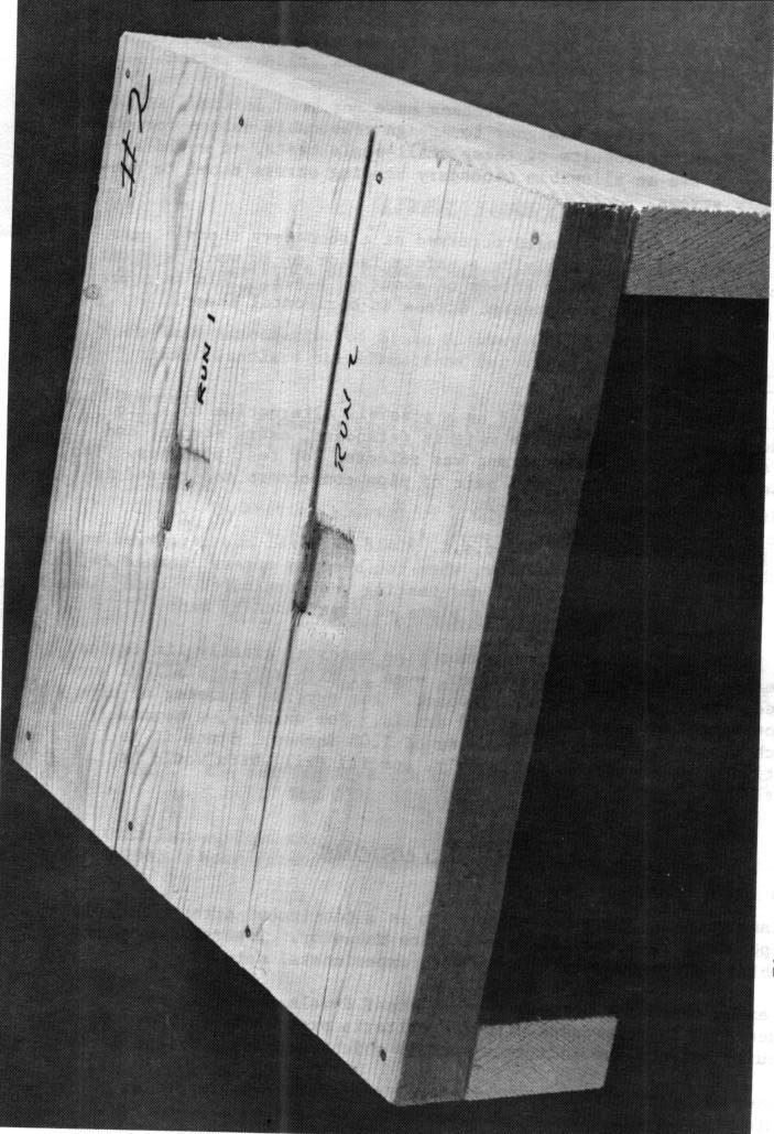
9 A comparison of theoretical and measured deflections along the longitudinal (parallel to stringers) and transverse centerlines is also presented in figure 3. The two profiles very nearly coincide over their full length. Connector Systems The initial search for suitable connectors preceded the development of the design theory for load transfer, which will be discussed later. Physical tests were first conducted on seven connector types as a screening process to determine which were most effective. An eighth connector type, steel pipe dowels, was tested by a different method and will be discussed separately in the supplemental tests section. There are two basic types of connectors -those with shear capacity only and connectors with both shear and moment capabilities. In each case, two panels, 42 by 84 by 5-1/4 inches, were joined by each of the seven methods. These assemblies were simply supported over a 72-inch span with the joints normal to the supports. A concentrated load was applied to one of the panels immediately adjacent to the joint at midspan. The deflection profile was recorded along the longitudinal centerline of the panels to assess load transfer capabilities of the system. Shear connectors.--five types of shear connectors were tested: wood splines, single steel splines, double steel splines, tapered tongue-andgroove joints, and rectangular tongue-and-groove joints. The steel splines were reasonably effective in reducing relative displacement across the joint, but there was an abrupt discontinuity in the shape of the deflection profile across the joint. There was relative displacement across the interface of all the other joints followed by complete shear failures along the joints. None of the above connectors was fully effective and most of the load was absorbed by the loaded panel. Shear and moment connectors.--two shear-moment connectors, solid steel dowels and hardwood oak dowels, were tested initially. Seven coldrolled steel dowels, 10 inches long by 1 inch in diameter, were installed over the middle half of the span. The length and placement patterns for the hardwood dowels were identical, but the diameter was 1-3/8 inches. Both were effective in transferring the combined loads across the joints. The panel pairs were loaded in 2,000-pound increments to a maximum concentrated load of 38,000 pounds. There was no indication of differential displacement of panels when using steel dowels, nor was there any apparent structural damage. however, upon dismantling the panels connected with wood dowels, a crack was found along the line of dowels in the loaded panel (fig. 4). After the dowel theory was finalized, it became apparent why failure occurred with the wood dowels and not with the steel dowels. The wood dowels, being more flexible and of greater diameter, deflected nearly 50 percent more and imposed stresses in the wood approximately 60 percent higher. The stress under the wood dowels was more than seven times the proportional limit stress. In general, for wood and steel dowels of equal diameter and of sufficient length for maximum efficiency, the stress under wood dowels will be 2 to 4-1/2 times the stress imposed by steel dowels. -7-

10 Figure 3.--Comparison of theoretical and measured deflections along longitudinal and transverse centerlines. (M ) Figure 4.--Crack along centerline of hardwood dowels, (M ) FPL
11 One further drawback with wood dowels is dimensional stability. The wood dowels for this study were turned on a lathe to precisely 1-3/8-inch diameter. Ten days later, the dowels had swelled to the extent that they no longer fit the predrilled panel holes. They required sanding before the connection could be made. A comparison of deflection patterns across a joint for shear-only and shear-moment connectors is shown in figure 5. The shear connectors are obviously unsatisfactory. The flexibile hardwood dowels develop high stresses in the panels, but the Steel dowels perform satisfactorily. THEORETICAL ANALYSES Orthotropic Plate Analysis A glued-laminated wood bridge deck can be analyzed as an orthotropic plate. The differential equation for such a plate in the x-y plane is ( 5,6): where In general, this equation is not amenable to direct solution. One problem for which solutions are obtainable, however, is that of an infinite strip (fig. 6). -9-
12 Figure 5. --A comparison of centerline deflection patterns of panels joined by shear connector (spline) and shear-moment connectors (dowels). (M ) Figure 6. --Bridge deck analyzed as an infinite strip under uniform rectangular load. (M ) FPL
13 The wheel load P is uniformly distributed over an a-by-b rectangular area centered at (x,y) = (ξ,0) (fig. 6). It is assumed that the edges x = 0 and x = s are simply supported by the bridge stringers and that the slab extends indefinitely in the positive and negative y-directions. Thus, the deflections, moments, and shears must approach zero as y approaches ± infinity. Although a glued-laminated bridge deck is, of course, of finite dimensions, the fact that the stiffness is much greater in the x-direction than in the y-direction causes the deflections, etc., to diminish very rapidly away from the loaded area. Thus, modeling the bridge deck as an infinite strip gives a very close approximation to the true solution. First considering the case of a line load along the x-axis (i.e., b = 0), the load is expressed as a Fourier series: where, in this case: If H < of plate where y > 0 is (6): as is the case for wood, the solution for the portion (1) where -11-
14 From the above solution for deflection, the moments and shears per unit width can also be obtained in series form, since: Once the solution for a line load is known (eq. 1), the solution for a rectangular loaded area (b > 0) can be found by integration f(y) defines the plate response (deflection, moment, or etc.) to a 1ine load on the x-axis, then f, the response at y = y to the distributed load, is: (2) where Since the line load solution is valid only for y > 0, it is necessary to consider the symmetry, or asymmetry, of-the response when First, rewrite equation (2) as: FPL
15 When f is an even, or symmetric, function (i.e., when f ( y) = f (y)), as for deflection, then and it follows that: (3) If f is odd (i.e., f (-y) = -f(y)), as it is for Q y, then and (4) Thus, from the series solution for a line load (eq. 1), the solution can be obtained for a strip uniformly loaded over a rectangular area (eqs. 3 and 4). This approach gives results which agree very closely with experimental data (fig. 3). Steel Dowel Analysis Due to fabrication, transportation, and erection limitations, as well as consideration of possible contraction and expansion, a gluedlaminated bridge deck is normally constructed from fairly narrow panels (usually not wider than 4 ft.). In order for the panels to act as a continuous, uninterrupted slab, it is necessary to provide connectors with the structural capacity to prevent relative displacements and rotations between adjacent panels. The earlier tests have shown that steel dowels are well suited for this purpose. The dowels are installed at the midthickness of the panels and are embedded to half their length in each of the panels being joined. To design such a connector system, it is possible to employ a technique which has been used by Kuenzi (4) and Stluka 5 to predict the behavior of nailed and bolted joints. The dowel is considered to be a beam supported by an elastic foundation. The perpendicular-to-grain compression stress in the wood foundation is proportional to the deflection of the beam (dowel) induced by the shear and moment in the deck (fig. 7). 5 Stluka, R. T. Theoretical Design of a Nailed or Bolted Joint Under Lateral Load. M.S. Thesis, University of Wisconsin
16 The joint is designed so that the stresses in both the dowel and the wood are at or below their proportional limits. The length of the dowel is of major importance. If too short, it will act as a rigid body, causing excessively high stresses in the wood. Making the dowel excessively long will not enhance its performance and will result in material waste. Associated with the dowel length is a constant, λ, which is defined as: where k = k o d; k o = foundation modulus (pounds per cubic inch), see appendix: d = dowel diameter (inch); and EI = flexural stiffness of dowel (pound-square inch). Thus, λ has units of inch -1 and represents the inverse of a characteristic length. For satisfactory transfer of load between the dowel and the wood foundation, with minimum stresses, it is necessary that λ 3. Coefficients for the foundation deflection and for the bending moment along the length of the dowel 5 with = 3 are shown in figures 8 and 9. From figure 8, the maximum total deflection under the dowel is: The stress in the wood foundation is equal to the deflection, z, times the foundation modulus, k o, and may not exceed the proportional limit stress. Because the foundation stress is perpendicular to the grain, a diameter factor, f, (8) is applied to Thus, the deflection may not be greater than and the interaction equation which defines the limiting combinations of shear and moment is: FPL
17 Figure 7.--Dowel considered to be a beam supported by an elastic foundation. (M ) Figure 8.--Coefficients for elastic foundation deformation due to shear and moment loads. Figure 9.-- Coefficients for dowel moment due to shear and moment loads. (M ) (M ) -15-
18 Similarly, from figure 9, the maximum moment in the dowel is: The dowel moment is limited to that which causes the steel elastic limit stress to be reached, M EL. Therefore, (6) gives the combinations of joint shear and moment which produce yielding of the dowel. Usually, the stresses in the wood will control the design, and the dowel stress need be computed only as a check. DESIGN CHARTS AND TABLES Deck Design The theoretical slab analysis presented earlier is, obviously, not amenable to simple hand calculations. Therefore, a digital computer was programed to perform the necessary computations, and the results have been reduced to a set of easy-to-use design charts which cover the practical range of design problems. The charts are presented in terms of dimensionless parameters. The following relationships between elastic properties, which are reasonable for most wood species, have been assumed (8 ): With the above parameters, design charts were developed to define forces (bending moments and vertical shears) in the two principal directions. Primary denotes the span or x-direction which coincides with the longitudinal grain of the wood. Secondary forces are those acting parallel to the supports (y-direction) or perpendicular to grain. All unit forces are a maximum when the wheel load is centered (i.e., when ξ/s = 0.5, fig. 6) except for primary shear. The maximum shear occurs under the wheel edge nearest to the support, and its magnitude increases as the load approaches the support. In calculating shear in beams, there are many different rules which are used for positioning FPL
19 the load. Therefore, multiple graphs are presented for primary shear, each graph corresponding to a different load position. Bending stresses can be computed from the unit bending moment (M) and are equal to 6M/t 2. Using the common assumption of a parabolic distribution of shear stresses across the depth, the horizontal shear stress (which is equal to the vertical shear stress) is 3R x /2t, where R x denotes the primary vertical unit shear force. Secondary shear, R, y acts perpendicular to grain (rolling shear), and stresses can be calculated in the same manner. The curves of figure 10 are used to determine the maximum primary unit bending moment, M x (inch-pound per inch). The abscissa is the ratio of tire width to span, a/s, and the ordinate gives the ratio of bending moment to wheel load, M x /P. Each curve corresponds to a particular ratio of tire contact length to tire width, b/a, from 0.25 to 2.0. Figures 11 through 14 define the maximum primary shear, R x (pound per inch), in terms of the ratio of wheel load to span, P/s, for various load positions, ξ/s = 0.5 to 0.1. The curves are terminated at a/s = 2ξ/s because past this value part of the load would be off the span. Similarly, figures 15 and 16 define the maximum secondary moment, M y, and shear, R y. The shears are denoted as R, rather than Q, because they include terms to account for torsional stresses (the "Kirchhoff effect"), and are defined as: Although deflection criteria do not generally govern the design of bridge decks, figure 17 is presented in the event that such computations are needed. The maximum deflection, w (inch), is expressed in terms of the quantity Ps 2 /E x t 3, where t is the deck thickness. The charts are applicable to any case where a single wheel load between stringers controls the design. Their use will be demonstrated later in a sample problem. Dowel Design Since moments and shears are not constant across the span, it would be grossly overconservative to design the steel dowel connectors for the maximum unit values determined in the deck analysis. Therefore, in designing the dowels, it will be assumed that the total moment and shear which act across a deck joint are shared equally by the dowels. Dowels designed in this manner have performed adequately in laboratory tests. -17-
20 Figure 10.--Primary moment coefficients. (M ) Figure 11.--Primary shear coefficients for ξ/s = 0.5 (center load). (M )
21 -19-
22 FPL
23
24 Figures 18 and 19 present the total moment and shear, denoted M y (inch-pound) and R y (pound), in nondimensional form. The moment-shear interaction relationship (eq. 5) is presented graphically in figure 20 for various dowel diameters. In this figure, values of k = 180,000 pounds per cubic inch and 0 = 1,000 pounds per square inch (p.s.i.) are assumed. The value for the foundation modulus is that which was determined experimentally (see appendix) and 1,000 p.s.i. is a reasonable value for the proportional limit stress. For other values of (8), it is only necessary to multiply the capacity values from figure 20 by the ratio Each line is identified by dowel diameter and represents dowel capacity under combined shear and bending loads. This graph can be used directly to determine the required size and number of dowels. A straight line having a slope equal to the ratio of total shear to total moment will cross dowel capacity lines at points proportional to the imposed loads. Either the shear capacity or moment capacity at the point of intersection can be used to determine the number and size of dowels. It is only necessary then to divide the total force (either shear or moment) by the corresponding capacity of a given size dowel to determine the required number. A more precise method is to use the information in table 2 and compute the required number of dowels by: (7) where = minimum number of dowels; = shear and moment capacities, table 2; = total secondary moment and shear, figures 18 and 19; and = proportional limit stress in compression perpendicular to grain. The values of R D and M D in table 2 are based on the wood stresses controlling the design, and are the intercepts of the capacity lines in figure 20. This approach assumes that the maximum shear force occurs simultaneously with the maximum moment, which is generally not the case. Maximum moment occurs near the center of the load and maximum shear falls at the edge of the wheel. Therefore, these results are somewhat conservative. Steel stresses are likely to control only for the smaller diameters but should be checked nevertheless, Equation (6), which defines the steel design criteria, can be rewritten to solve for the minimum elastic FPL
25 Figure 18.--Total secondary moment coefficients. (M ) -23-
26 Figure 19.--Total secondary shear coefficients. (M ) FPL
27 -25-
28 limit which is needed, Noting that equation (6) becomes: and (8) where = minimum elastic limit of steel; and = coefficients, table 2. If is too high, this can be remedied by increasing the size of dowel used (and recomputing the number needed, eq. (7)) or simply by increasing the number of dowels. It should be noted that the yield point of common bar stock is quite high. Most cold-finished bar stock has a yield point exceeding 60,000 p.s.i., and quenched and tempered bars can be obtained with yield points up to 130,000 p.s.i. Table 2 also lists values of λ and diameter factor, f, and defines the minimum length for each size dowel. Dowel spacing must be left to the judgment of the designer. One method is to simply divide the center-to-center distance between stringers by the required number of dowels. End dowels in each span are positioned one-half of a space off the stringer centerlines. Dowels will then be equally spaced over the full length of the panel and this uniform pattern will reduce chances for fabrication errors. SAMPLE PROBLEM To illustrate the use of the design charts, the following problem is considered: Design a transverse deck for a loading of P = 12,000 lb., a= b = 15 in.; assuming the effective span between stringers is 72 inches, the allowable wood foundation stress, is 1,200 p.s.i., and the center of the wheel is positioned 22-1/2 inches from the support for the primary shear computation. Compute a/s = b/a = 1.0 ξ/s = FPL
29 Table 2.--Dowel design data 1 1 For ko = 180,000 lb. per cu. in.; = 1,000 p.s.i.; and = 3. 2 U.S. Forest Products Laboratory, Wood Handbook. USDA Agr. Handb. No
30 From figures 10 through 16: M x /P = 0.48 M x = 5,760 inch-pounds per inch R x /(P/s) = 2.3 (from interpolating between figs. 12 and 13) M y /P = R y /(P/s) = 0.98 R x = 383 pounds per inch M y = 696 inch-pounds per R y = 163 pounds per inch inch The stresses associated with these moments and shears can be readily calculated. For a nominal 6-inch deck (t = in.), the stresses are: Primary bending = 6M x /t 2 = 1,310 p.s.i. Horizontal shear Secondary bending = 6M y /t 2 = 159 p.s.i. Rolling shear Thus, a 6-inch deck is adequate if the allowable design stresses for the material equal or exceed those listed above. If desired, the maximum deflection of the deck relative to the stringers can be determined from figure 17. Thus, for To design the dowel connectors, it is first necessary to compute From figures 18 and 19, M y /Ps = M y = 28,500 inch-pounds R y /P = 0.36 R y = 4,320 pounds From figure 20, a line having a slope of R y /M y = 0.15 crosses the 1-1/4-inch dowel line at a moment capacity of 4,150 inch-pounds. The number of 1-1/4-inch dowels is: Use 6. FPL
31 or From equation (7), selecting 1-1/4-inch dowels, the required number is: Use 6. The minimum dowel length is given in table 2 as 17 inches, From equation (8), the minimum elastic limit stress for the steel is: SUPPLEMENTAL TESTS Dimensional Stability and Preservative Treatment To study the dimensional stability of bridge deck panels subjected to numerous wetting and drying cycles, eight of the panels from the 1969 joint connector tests were taken to an exposure site at Madison, Wis. Six of the panels were treated with creosote, three of which were incised prior to treatment, and two panels were untreated. The panels were nailed with 3/8-inch-diameter ring shank nails to simulated bridge stringers and exposed outdoors for 3 years and 7 months (fig. 21). Periodic inspection trips were made to the site to record dimensional changes and moisture contents of the panels. Measurements of the transverse dimensions were taken at both ends of the panels between pairs of escutcheon pins placed 37 inches apart. Moisture probes were installed within the decks and readings were taken with an electrical resistance meter. The maximum dimensional change for the treated panels was ±0.25 percent. Little difference was noted between the incised and unincised panels. There is probably sufficient play in a field joint to accommodate a 0.25 percent increase in panel widths up to 4 feet. Associated moisture contents ranged from 8.9 to 14.8 percent. With untreated panels, dimensional changes ranged from +0.8 to -0.4 percent while the moisture fluctuated from 10 percent to above fiber saturation. This demonstrates the effectiveness of preservative treatment in retarding moisture changes and reducing dimensional changes. The preservative was a creosote-petroleum solution. Treatment was in accordance with AWPA Standards C1-67 and C28-67 for ground contact use. Thirteen assays were taken, from both incised and unincised panels, with 3/8-inch-diameter plug cutters from the outer 5/8 inch of deck. -29-
32 Douglas-fir is a difficult species to treat, and it is virtually impossible to get effective treatment without incising. This fact is well illustrated in comparing the retentions of these two panels. Petroleum extractions taken shortly after treatment disclosed a preservative content of 17.0 pounds per cubic foot (p.c.f.) for incised panels and only 5.2 p.c.f. for unincised. Assays were taken again 3-1/2 years later immediately adjacent to the original ones. No changes were found in the unincised panels. Preservative content in the incised panels had dropped to 15 p.c.f., still well above the 12 p.c.f. requirement. It is assumed that this loss occurred shortly after the panels were treated due to surface bleeding and evaporation of solvents, and that future losses in preservative would be minimal. One of the untreated panels received a coating of coal-tar mastic to protect the end grain. This simple operation greatly retarded checking in the ends of the panel. A comparison of end checking is shown in figure 22. Specimen A, with the mastic seal, exhibits practically no checking. The large vertical split on the left side was a result of handling and was not a check. Checks in the unprotected slab can easily be traced back 1 inch or more. Creosote-treated panels exhibited virtually no end checking. To further evaluate the performance of glued-laminated panels under actual service conditions, experimental test decks have been applied to six Forest Service bridges throughout the United States. No problems have been observed due to dimensional stability nor to loss in preservative treatment in more than 6 years. Experimental Evaluation of Exposed Panels To determine the effect of outdoor exposure on the structural behavior of glued-laminated panels, the eight panels from the exposure study were returned to the lab for further testing. The two untreated panels had previously been tested with tongue-andgroove joints in the connector study. The edges were squared up and the two sections were glued together to make a 7- by 7-foot panel. Two of the three treated and incised panels were likewise glued together. These panels had been previously tested with dowel connectors and seven holes were present in the glueline. The other four panels were joined into two pairs using seven 1-1/4-inch diameter steel dowels. Theoretically the dowels and deck were balanced for a design load of 16,000 pounds. The dowel-connected panels were loaded in two ways: (1) With the 20- by 15-inch load block centered over the joint to maximize the moment at the joint, and (2) with the edge of the block over the joint to maximize joint shear. In all cases, the test specimens were loaded to 50,000 pounds without apparent failures of any kind. At this load, the theoretical primary and secondary bending stresses were 4,800 and 610 p.s.i. respectively, and the shear stresses were 360 and 160 p.s.i. The preservative treatment apparently had no adverse effect on the glue bond. FPL
 Outside edge and backside of a 1-inch strip cut from mastic-coated panel.")
33 Figure 21.--Glued-laminated deck panels exposed outdoors to evaluate dimensional stability. (M ) Figure 22.--Comparison of end checking of untreated panels (A) Outside edge and backside of a 1-inch strip cut from mastic-coated panel. (B) Strip cut from panel without end-grain protection. (M ) -31-
34 Small-Scale Tests Since the 50,000-pound load capacity of the test apparatus was insufficient for destructive testing of the 5-1/4-inch-thick deck panels, small-scale tests were conducted. The purpose of these tests was to determine which of the four stresses, primary or secondary bending or primary or secondary shear, controls ultimate load capacity. Allowable values for the primary stresses, bending parallel to grain and horizontal shear, are well defined. This is not the case, however, with the secondary stresses, bending perpendicular to grain and rolling shear. Nine test specimens consisting of nominal l-inch-thick Douglas-fir board material were cut into 9-1/2- by 9-1/2-inch squares. The moisture content of the nine specimens averaged 12 percent. These plates were then secured to nominal 1- by 2-inch pseudo stringers with four sixpenny finishing nails (2 by in.) spaced 3 inches on center of each side. The supports were positioned perpendicular to the grain direction as is the case with a normal bridge deck. These specimens were approximately 1:6 scale relative to the 5-1/4-inch deck panels. Three different sized load blocks, 1- by 1-, 2- by 2-, and 3- by 3-inch, were used on each of three sets of specimens to induce different stress levels within the plates. Each specimen was then loaded to destruction and the types of failures were noted. Theoretical stresses, at initial failure and ultimate load, were then computed using the deck design charts previously discussed. Horizontal shear was never a factor in any of these tests. In each case, there were two separate and successive failures. The character of these failures depended on the size of loading block. The smallest load blocks (1- by 1-in.) imposed high rolling shear stresses on the plates adjacent to the load block. However, even before this there were severe compression failures (perpendicular to grain) under the load block as shown in figure 23. But compression or bearing failures did not adversely affect structural performance of the plates. Initial structural damage first occurred at an average load of 1,920 pounds in rolling shear at a stress of 660 p.s.i. These shear failures extended from support to support and disrupted plate continuity. Ultimate failure followed in primary bending at a load of 1,980 pounds, At this point, the specimen s behavior was somewhere between that of a plate and a beam. Therefore, the plate theory would underestimate primary bending stresses (8,700 p.s.i.), whereas the beam theory would grossly overestimate bending stresses (32,000 p.s.i.). It should be noted that the load width to span ratio, a/s, was only 0.125, which would be an unlikely situation. This would equate to a stringer spacing in excess of 13 feet for an H2O wheel load. For practical design situations, the rolling shear stress would not usually exceed 50 p.s.i. The 2- by 2- and 3- by 3-inch blocks represent load-to-span ratios, a/s, of 0.25 and 0.375, respectively. These two larger sizes performed in much the same manner. Although the 2- by 2-inch blocks produced minor bearing failures under the loaded area, these had no influence on plate performance. Initial failures, in both cases, occurred in rolling shear at an average stress level of 400 p.s.i. at loads of 2,280 and 3,870 pounds, respectively. These failures, however, were very minor and local in nature and the deck continued to perform as a continuous plate. Ultimate loads were 2,540 and 4,650 pounds, respectively. Failures FPL
35 -33-
36 were essentially in primary bending at a stress level which averaged 12,400 p.s.i.; this is the listed modulus of rupture for coast-type Douglasfir. Most of the specimens also exhibited perpendicular-to-grain bending failures in the secondary direction. The corresponding average secondary bending stress at failure was 1,280 p.s.i., or slightly higher than 10 percent of the primary bending strength. Because allowable secondary stresses have not been defined, it is necessary for the bridge designer to assign reasonable values for these stresses. From the results of these small-scale tests, it would appear reasonable to use an allowable secondary bending stress equal to one-tenth the primary stress. Major rolling shear failures occurred at a secondary shear stress level of 660 p.s.i., and applying a safety factor of 10 would suggest an allowable secondary shear stress of about 65 p.s.i. This is approximately one-third of the clear wood design stress in horizontal shear. Steel Pipe Dowels Steel pipe dowels were tested as a possible alternative to solid steel dowels. Of the available weights (standard, extra strong, and double-extra strong), extra strong was selected for test purposes. Two panel sections were joined by a pair of pipe connectors and tested in the apparatus shown in figure A-2. The pipe was standard 20,000-p.s.i. yield material and performed well up to that stress level. However, when the bending stress reached 24,500 p.s.i. the pipes started to fail and testing was terminated. Upon dismantling the sections it was found that the pipes were permanently bent. The low bending strength of common pipe material greatly limits the performance of pipe dowels. However, even if high-strength alloys were selected, there is one further drawback. The outside diameter of pipe does not match the size of standard drills. For example, a nominal 3/4-inch pipe has an outside diameter of 1.05 inches. Since it is imperative that the dowels fit snugly, special drill bits would be required. CONCLUSIONS By analyzing a glued-laminated deck as a continuous orthotropic plate, it is possible to accurately predict its behavior. Theoretical values thus obtained agreed very closely with experimental data. Of eight connector systems tested, steel dowels performed best. When designed in accordance with the criteria presented, they provide continuity between the individual panels which comprise a bridge deck. Preservative treatment with creosote is effective in retarding moisture changes and associated dimensional changes of exposed deck panels. FPL
37 A fast and simple procedure has been developed for the design of glued-laminated bridge decks and steel dowel connectors for deck panels placed in a transverse direction to the stringers. All the necessary design information has been reduced to a series of easyto-use charts, tables, and equations (figs. 10 to 20, table 2, eqs. 7 and 8). LITERATURE CITED American Institute of Timber Construction Timber construction standards, AITC th ed. American Association of State Highway Officials Standard specifications for highway bridges. 10th Edition. Bohannan, B FPL timber bridge deck research. J. Struc. Div., Amer. Soc. of Civil Eng., Vol. 98, No. ST3. Kuenzi, E. W Theoretical design of a nailed or bolted joint under lateral load. U.S. Forest Prod. Lab. Rep. No. D1951. Lekhnitskii, S. G Anisotropic plates. Trans. from 2d Russian ed. by S. W. Tsai and T. Cheron, Gordon and Breach Publ. Timoshenko, S., and Woinowsky-Krieger, S Theory of plates and shells. 2d Edition. McGraw-Hill Book Co. Trayer, G. W The bearing strength of wood under bolts. USDA Tech. Bull. No U.S. Forest Products Laboratory Wood Handbook. USDA Agr. Handb. No
38 APPENDIX FOUNDATION PROPERTIES OF WOOD To apply the dowel theory, it was first necessary to define the foundation properties of the wood; namely, the stress at proportional limit, and the foundation modulus, k, Apparently little work has o been done in this area and physical tests were needed. Eighteen tests were run using standard bolt-bearing apparatus (fig. A-l). The specimens were cut from nominal 2 by 4 dimension Douglas-fir lumber. No attention was given to grade of lumber; rather it was selected on the basis of saw cut, i.e., flat grain or edge grain. Loads on the dowels are always applied perpendicular to grain; tests were therefore made to see if foundation properties are different in the radial and tangential directions. No significant difference was observed in the two directions. Three different dowel diameters--1/2 inch, 1 inch, and 1-1/2 inch-- were used in these tests. Holes were drilled to provide a snug fit over the dowels. Wood blocks were generally cut into squares, 3-1/2 by 3-1/2 inches. However, half of the blocks used with 1- and 1-1/2-inch dowels were cut 7 inches in length to determine if the material on either side of the bolt contributes to strength. No difference was noted, Failures were concentrated locally at the contact bearing surface of the dowel. Displacement or slip at failure is extremely small and edge distance does not seem to be a factor. Load-slip data were obtained with an x-y plotter. Initially the specimens were cycled to a displacement of about inch to properly seat the dowels. Then the specimens were loaded to failure. Proportional limit stresses were determined from the load-slip curves in the usual manner. The foundation modulus, k, has the units of pounds per cubic o inch and is the stress at proportional limit divided by the slip at that level. Test results are presented in table A-1. The average stresses at proportional limit are 2,155, 1,640, and 1,490 p.s.i. for the 1/2-, 1-, and 1-1/2-inch dowels, respectively. This apparent variation can be explained, For loads acting perpendicular to the grain, it is necessary to apply a diameter factor to obtain basic stress values. Proportional limit stresses are higher for small diameter dowels. This is probably due to the edge effect which forces fibers into tension rather than pure compression. The diameter factors are listed in table 2. Applying the appropriate factor to these tests for three dowel diameters reduces the basic stresses to 1,280, 1,290, and 1,310 p.s.i., which is in very close agreement, Trayer (7) found the stress at proportional limit to be 1,140 p.s.i. for Douglas-fir. The average foundation modulus for the 18 specimens is 180,000 pounds per cubic inch. A slight variation in this value will not be significant since this factor is taken to the fourth root. FPL

39 Figure A-1.--Bolt-bearing apparatus to determine foundation properties. (M )
40 Table A-l.--Foundation properties of Douglas-fir perpendicular to grain FPL
. A slight gap was left between the panels in order to affix strain gages to the dowels.")
41 Further tests were conducted to compare physical results with theoretical values based on the elastic foundation properties previously obtained. Two panel sections were connected by a pair of steel dowels (fig. A-2). A slight gap was left between the panels in order to affix strain gages to the dowels. The assembly was then simply supported in the weak direction with the joint parallel to the supports. Loads were applied at the quarter-points to provide an area of constant moment over the middle half of the assembly. Dial indicators were mounted on the upper surface to measure foundation deformation under load. Table A-2 shows how the theoretical moments compare to the moments as measured by the strain gages and as measured by deformation of the elastic foundation. The right-hand column shows the magnitude of deformation within the elastic foundation under the imposed moment. Very close agreement between theoretical and measured moments was achieved. Figure A-2. --Panel sections connected by steel dowels. (M ) -39-
42 Table A-2.--Comparison of theoretical moment to moments measured by strain gages and by deformation of elastic foundation FPL
43 LIST OF SYMBOLS tire contact width tire contact length dowel coefficients, table 2 dowel diameter bending stiffness in x- and y-directions torsional stiffness moduli of elasticity in x- and y-directions bending stiffness of steel dowel dowel diameter factor modulus of rigidity for shear deformations in the x-y plane -41- wood foundation modulus dowel penetration length bending moment bending moment at dowel connection dowel moment capacity dowel moment which produces elastic limit stress unit bending moments in x- and y-directions unit twisting moment number of dowels wheel load load per unit area term in Fourier expansion of load shear at dowel connection unit shears in x- and y-directions

44 dowel shear capacity unit "Kirchhoff shears" in x- and y-directions effective deck span between stringers deck thickness maximum deck deflection coordinate axes deflection under dowel Poisson's ratios; the first subscript denotes direction of stress, the second denotes associated deformation location of center of load along x-axis proportional limit stress in compression perpendicular to grain FPL U.S. Government Printing Office /27
SIMPLIFIED DESIGN PROCEDURE FOR GLUED-LAMINATED BRIDGE DECKS
 ABSTRACT Procedures have recently been developed for the design of glued-laminated bridge decks and for steel dowel connectors. However, since most bridges are designed in accordance with the Specifications
Korean standards of visual grading and establishing allowable properties of softwood structural lumber
 Korean standards of visual grading and establishing allowable properties of softwood structural lumber Park, Moon-Jae 1, Shim, Kug-Bo 1 ABSTRACT Korean standards related to wood products such as "Sizes
Glulam Curved Members. Glulam Design. General Glulam Design. General Glulam Beams are Designed in the SAME Manner as Solid Sawn Beams
 Glulam Curved Members Glulam Design General Glulam Beams are Designed in the SAME Manner as Solid Sawn Beams There is an Additional Adjustment Factor, C v, the Volume Factor C v and C L (Lateral Stability
RlGIDITY AND STRENGTH OF WALL FRAMES BRACED WlTH METAL STRAPPING
 RlGIDITY AND STRENGTH OF WALL FRAMES BRACED WlTH METAL STRAPPING information Reviewed and Reaffirmed March 1955 No. R1603 UNITED STATES DEPARTMENT OF AGRICULTURE FOREST SERVICE FOREST PRODUCTS LABORATORY
2002 ADDENDUM to the 1997 NDS and PRIOR EDITIONS
 AMERICAN FOREST & PAPER ASSOCIATION American Wood Council Engineered and Traditional Wood Products March 2002 2002 ADDENDUM to the 1997 NDS and PRIOR EDITIONS The 2001 Edition of the National Design Specification
American Institute of Timber Construction 7012 South Revere Parkway Suite 140 Centennial, CO Phone: 303/ Fax: 303/
 American Institute of Timber Construction 7012 South Revere Parkway Suite 140 Centennial, CO 80112 Phone: 303/792-9559 Fax: 303/792-0669 404.1. SCOPE STANDARD FOR RADIALLY REINFORCING CURVED GLUED LAMINATED
SHEAR STIFFNESS OF TWO-INCH WOOD DECKS FOR ROOF SYSTEMS U.S.D.A. FOREST
 SHEAR STIFFNESS OF TWO-INCH WOOD DECKS FOR ROOF SYSTEMS U.S.D.A. FOREST SERVlCE RESEARCH PA PER FPL 155 1972 Forest Products Laboratory, Forest Service, U.S. Department of Agriculture, Madison, Wisconsin
Lawrence A. Soltis, M. and Robert J. Ross, M. 1
 REPAIR OF WHITE OAK GLUED-LAMINATED BEAMS Lawrence A. Soltis, M. and Robert J. Ross, M. 1 Abstract Connections between steel side plates and white oak glued-laminated beams subjected to tension perpendicular-to-grain
Effect of shoulders on bending moment capacity of round mortise and tenon joints
 Effect of s on bending moment capacity of round mortise and tenon joints Carl Eckelman Yusuf Erdil Eva Haviarova Abstract Tests were conducted to determine the effect of close-fitting s on the bending
Glulam Connection Details
 T E C H N I C A L N O T E Glulam Connection Details Note: This version is superseded by a more current edition. Check the current edition for updated design and application recommendations. ENGINEERED
Dowel connections in laminated strand lumber
 Dowel connections in laminated strand lumber Cranswick, Chad J. 1, M c Gregor, Stuart I. 2 ABSTRACT Laminated strand lumber (LSL) is a relatively new structural composite lumber. As such, very limited
DESIGN EQUATION FOR MULTIPLE- FASTENER WOOD CONNECTIONS
 DESIGN EQUATION FOR MULTIPLE- FASTENER WOOD CONNECTIONS By John J. Zahn, 1 Member, ASCE ABSTRACT: A compared design equation is presented for the design of multiple fastener connections of wood members.
The Behaviour Of Round Timber Sections Notched Over The Support On The Tension Face. Justin Dewey
 The Behaviour Of Round Timber Sections Notched Over The Support On The Tension Face Justin Dewey Need for research In Queensland there are approximately 400 timber bridges still in use. Very little research
IMPROVING PAINT PERFORMANCE ON SOUTHERN PINE BY RELIEF OF MACHINING STRESSES AND CHROMIC ACID TREATMENT
 IMPROVING PAINT PERFORMANCE ON SOUTHERN PINE BY RELIEF OF MACHINING STRESSES AND CHROMIC ACID TREATMENT USDA Forest Service U.S. Department of Agriculture Research Paper Forest Service FPL 271 Forest Products
ADDENDUM (February 2014) 2012 NDS Changes John Buddy Showalter, P.E., Bradford K. Douglas, P.E., Philip Line, P.E., and Peter Mazikins, P.Eng.
 2012 NDS Changes John Buddy Showalter, P.E., Bradford K. Douglas, P.E., Philip Line, P.E., and Peter Mazikins, P.Eng.") ADDENDUM (February 2014) 2012 NDS Changes John Buddy Showalter, P.E., Bradford K. Douglas, P.E., Philip Line, P.E., and Peter Mazikins, P.Eng. 1) Add to section on Dowel-type Fasteners as follows: Section
ADDENDUM (February 2014) 2012 NDS Changes John Buddy Showalter, P.E., Bradford K. Douglas, P.E., Philip Line, P.E., and Peter Mazikins, P.Eng. 1) Add to section on Dowel-type Fasteners as follows: Section
Wood. Wood construction
 CEEN 3144 Construction Materials Wood Francisco Aguíñiga Assistant Professor Civil Engineering Program Texas A&M University Kingsville Page 1 Wood construction Page 2 1 Wood construction Page 3 Advantages
Lawrence A. Soltis. James K. Little
 ANGLE TO GRAIN STRENGTH OF DOWEL-TYPE FASTENERS Lawrence A. Soltis Supervisory Research Engineer Forest Products Laboratory,' Forest Service U.S. Department of Agriculture, Madison, WI 53705 Suparman Karnasudirdja
EVALUATION OF METHODS OF ASSEMBLING PALLETS RESEARCH PAPER FPL U. S. DEPARTMENT OF AGRICULTURE FOREST SERVICE FOREST PRODUCTS LABORATORY
 EVALUATION OF METHODS OF ASSEMBLING PALLETS U. S. D. A. FOREST SERVICE RESEARCH PAPER FPL 213 1973 U. S. DEPARTMENT OF AGRICULTURE FOREST SERVICE FOREST PRODUCTS LABORATORY MADISON,WIS. ABSTRACT The performance
Connection Philosophy. p NDS Chapter-by-chapter description Changes from previous editions Examples. Part 1: Member Design Webinar.
 Outline ASD and LRFD with the 2005 NDS Part 2 Connection Design Presented by: John Buddy Showalter, P.E. Vice President, Technology Transfer Connection philosophy p NDS Chapter-by-chapter description Changes
THE ENGINEERED WOOD ASSOCIATION
 D A T A F I L E APA Performance Rated Rim Boards A rim board is the wood component that fills the space between the sill plate and bottom plate of a wall or, in second floor construction, between the top
Moment-Resisting Connections In Laminated Veneer Lumber (LVL) Frames
 Frames") Moment-Resisting Connections In Laminated Veneer Lumber (LVL) Frames Andy van Houtte Product Engineer-LVL Nelson Pine Industries Nelson, NZ Andy Buchanan Professor of Civil Engineering Peter Moss Associate
Moment-Resisting Connections In Laminated Veneer Lumber (LVL) Frames Andy van Houtte Product Engineer-LVL Nelson Pine Industries Nelson, NZ Andy Buchanan Professor of Civil Engineering Peter Moss Associate
Changes in the 2001 NDS for Wood Construction
 Changes in the 2001 NDS for Wood Construction Philip Line, P.E.; Dr. Robert Taylor, P.Eng.; John Buddy Showalter, P.E.; Bradford K. Douglas, P.E. Introduction The 2001 Edition of the National Design Specification
Dowel. Design. Performance-Based World of Concrete Official Show Issue. Lift-truck design changes require a new look at joint durability
 2007 World of Concrete Official Show Issue January 2007 Performance-Based Dowel Lift-truck design changes require a new look at joint durability Design By Wayne W. Walker and Jerry A. Holland S erviceability
Design of Bolted Connections per the 2015 NDS
 Design of Bolted Connections per the 2015 NDS EARN 0.1 ICC Continuing Education Unit (CEU) DES335-A Design of Bolted Connections per the 2015 NDS Description: This article provides an overview of a bolt
Load Tables, Technical Data and Installation Instructions
 W22. W22. W22. W22. W22 W22.. Simpson Strong-Tie Fastening Systems Structural Wood-to-Wood Connections Including Ledgers Designed to provide an easy-to-install, high-strength alternative to through-bolting
3.1 General Provisions
 WOOD FRAME CONSTRUCTION MANUAL 107 3.1 General Provisions 3.1.1 Prescriptive Requirements The provisions of this Chapter establish a specific set of resistance requirements for buildings meeting the scope
APA Performance Rated Rim Boards
 D a t a F i l e APA Performance Rated Rim Boards A Rim Board is the wood component that fills the space between the sill plate and bottom plate of a wall or, in second floor construction, between the top
AMTS STANDARD WORKSHOP PRACTICE. Bond Design
 AMTS STANDARD WORKSHOP PRACTICE Reference Number: AMTS_SWP_0027_2008 Date: December 2008 Version: A 1 Contents 1 Technical Terms...3 2 Scope...3 3 Primary References...3 4 Basic...3 4.1 Typical joint types...4
Design Nailed and Wood Screwed Connections with Spreadsheet. Course Content
 Design Nailed and Wood Screwed Connections with Spreadsheet Course Content INTRODUCTION The complete design of a wood structure includes the design of connections between the various structural members.
nineteen Wood Construction 1 and design APPLIED ARCHITECTURAL STRUCTURES: DR. ANNE NICHOLS FALL 2016 lecture STRUCTURAL ANALYSIS AND SYSTEMS ARCH 631
 APPLIED ARCHITECTURAL STRUCTURES: STRUCTURAL ANALYSIS AND SYSTEMS DR. ANNE NICHOLS FALL 2016 lecture nineteen wood construction and design Wood Construction 1 Timber Construction all-wood framing systems
Improved Arcan Shear Test For Wood
 Improved Arcan Shear Test For Wood Jen Y. Liu, Robert J. Ross, and Douglas R. Rammer USDA Forest Service, Forest Products Laboratory, 1 Madison, WI, USA Abstract A new shear test fixture design that uses
Skewed connections result when members frame to each
 Design of Skewed Connections LARRY KLOIBER and WILLIAM THORNTON ABSTRACT Skewed connections result when members frame to each other at an angle other than 90º. This paper provides some guidance in the
U. S. FOREST SERVICE RESEARCH NOTE FPL-0136 May 1966
 U. S. DEPARTMENT OF AGRICULTURE FOREST SERVICE FOREST PRODUCTS LABORATORY MADISON, WIS In Cooperation with the University of Wisconsin U. S. FOREST SERVICE RESEARCH NOTE FPL-0136 May 1966 SOME CAUSES OF
Nailed Structural-Use Panel and Lumber Beams
 D A T A F I L E Nailed Structural-Use Panel and Lumber Beams When roof load or span requirements are too great to allow use of commonly available dimension lumber or timbers, a box beam constructed of
STRENGTH OF GLUED LAMINATED SITKA SPRUCE MADE UP OF ROTARY-CUT VENEERS. R. F. LUXFORD, Senior Engineer
 STRENGTH OF GLUED LAMINATED SITKA SPRUCE MADE UP OF ROTARY-CUT VENEERS By R. F. LUXFORD, Senior Engineer Summary Wing spars and other wood airplane parts are now either made of solid wood or laminated
WITHDRAWAL AND LATERAL STRENGTH OF THREADED NAILS
 238 WITHDRAWAL AND LATERAL STRENGTH OF THREADED NAILS Douglas R. Rammer, Donald A. Bender, and David G. Pollock An experimental study on the performance of threaded nails was conducted to understand and
AN IMPROVED SHEAR TEST FIXTURE USING THE IOSIPESCU SPECIMEN
 AMD-VOl. 231/MD-VOl. 85 Mechanics of Cellulosic Materials 1999 ASME 1999 ABSTRACT AN IMPROVED SHEAR TEST FIXTURE USING THE IOSIPESCU SPECIMEN Jen Y. Liu, Dwight D. Flach, Robert J. Ross, and Gary J. Lichtenberg
STRUCTURAL TIMBER DESIGN
 STRUCTURAL TIMBER DESIGN to Eurocode 5 2nd Edition Jack Porteous BSc, MSc, DIC, PhD, CEng, MIStructE, FICE Director lack Porteous Consultancy and Abdy Kernlani BSc, MSc, PhD, CEng, FIStructE, FIWSc Professor
Featuring TJ Rim Board and TimberStrand LSL
 #TJ-8000 SPECIFIER S GUIDE TRUS JOIST RIM BOARD Featuring TJ Rim Board and TimberStrand LSL Multiple thicknesses, grades, and products to cover all your rim board needs 1¼" Thickness matches lateral load
ICC-ES Evaluation Report Reissued June 1, 2010 This report is subject to re-examination in one year.
 ICC-ES Evaluation Report ESR-2648 Reissued June 1, 2010 This report is subject to re-examination in one year. www.icc-es.org (800) 423-6587 (562) 699-0543 A Subsidiary of the International Code Council
ESR-2403 Reissued October 1, 2009 This report is subject to re-examination in one year.
 ICC-ES Evaluation Report ESR-403 Reissued October, 009 This report is subject to re-examination in one year. www.icc-es.org (800) 43-6587 (56) 699-0543 A Subsidiary of the International Code Council DIVISION:
Connection and Tension Member Design
 Connection and Tension Member Design Notation: A = area (net = with holes, bearing = in contact, etc...) Ae = effective net area found from the product of the net area An by the shear lag factor U Ab =
Structural Strength of Lapped Cold-Formed Steel Z-Shaped Purlin Connections with Vertical Slotted Holes
 Missouri University of Science and Technology Scholars' Mine International Specialty Conference on Cold- Formed Steel Structures (2014) - 22nd International Specialty Conference on Cold-Formed Steel Structures
Joint Evaluation Report
 0 Joint Evaluation Report ICC-ES (800) 423-6587 (562) 699-0543 www.icc-es.org 000 ESR-2909 Reissued 09/2017 This report is subject to renewal 09/2019. DIVISION: 06 00 00 WOOD, PLASTICS AND COMPOSITES SECTION:
MAT105: Floor Framing
 MAT105: Copyright 2007 American Forest & Paper Association, Inc. Because the common applications for wood framing are in residential construction, the details of this program will be based on the IRC which
Section 914. JOINT AND WATERPROOFING MATERIALS
 914.01 Section 914. JOINT AND WATERPROOFING MATERIALS 914.01. General Requirements. Joint and waterproofing material for use in concrete construction must meet the requirements of this section. 914.02.
VERSA-LAM. An Introduction to VERSA-LAM Products
 44 VERSA-LAM An Introduction to VERSA-LAM Products VERSA-LAM is one of the strongest and stiffest engineered wood products approved in the UK. 241 302 356 406 VERSA-LAM products are excellent as floor
EFFECTS OF GEOMETRY ON MECHANICAL BEHAVIOR OF DOVETAIL CONNECTION
 EFFECTS OF GEOMETRY ON MECHANICAL BEHAVIOR OF DOVETAIL CONNECTION Gi Young Jeong 1, Moon-Jae Park 2, KweonHwan Hwang 3, Joo-Saeng Park 2 ABSTRACT: The goal of this study is to analyze the effects of geometric
ICC-ES Evaluation Report
 ICC-ES Evaluation Report www.icc-es.org (800) 423-6587 (562) 699-0543 ESR-2608 Reissued January 2016 This report is subject to renewal January 2017. A Subsidiary of the International Code Council DIVISION:
LVL8 H1.2 GENERAL FRAMING. Eco Friendly Revolutionary H1.2 Treatment Azotek by Zelam
 LVL8 H1.2 GENERAL FRAMING Eco Friendly Revolutionary H1.2 Treatment Azotek by Zelam NPIL/MARCH2015 Introduction to NelsonPine LVL8 H1.2 NelsonPine LVL is an engineered wood composite made from rotary peeled
Connection Design Examples
 Connection Design Examples Using the 2015 NDS (DES345) Lori Koch, P.E. Manager, Educational Outreach American Wood Council Adam Robertson, M.A.Sc., P.Eng. Manager, Codes and Standards Canadian Wood Council
F'II'XURAI PROPERTIES. and DIiIENSIONAL STABILITIES of two ronsrsrfcions of 4 8inch,,l SOUTHERN PINE PIY WOOD. ris on m p o f I( F
 CIRCULAR 210 j ris on m p o f F'II'XURAI PROPERTIES I( F and DIiIENSIONAL STABILITIES of two ronsrsrfcions of 4 8inch,,l SOUTHERN PINE PIY WOOD Agricultural Experiment Station AUBURN UNIVERSITY R. Dennis
Dowels for the 21st Century
 Dowels for the 21st Century by Wayne W. Walker and Jerry A. Holland sing plate dowels in slabs on ground for shear load transfer at the joints offer many advantages over the traditional round dowels. By
1/2/2016. Lecture Slides. Screws, Fasteners, and the Design of Nonpermanent Joints. Reasons for Non-permanent Fasteners
 Lecture Slides Screws, Fasteners, and the Design of Nonpermanent Joints Reasons for Non-permanent Fasteners Field assembly Disassembly Maintenance Adjustment 1 Introduction There are two distinct uses
A STUDY ON PATTERN DAMAGE OF FINGER JOINTS IN BAMBOO LAMINATED BEAMS
 A STUDY ON PATTERN DAMAGE OF FINGER JOINTS IN BAMBOO LAMINATED BEAMS Agus Rivani * * Abstract The aim of this study was to know the pattern damage of finger joints in bamboo laminated beams. The dimension
ESR-1254 * DELETED BY CITY OF LOS ANGELES. Reissued April 1, 2006 This report is subject to re-examination in one year.
 ESR-1254 Reissued April 1, 2006 This report is subject to re-examination in one year. www.icc-es.org Business/Regional Office 5360 Workman Mill Road, Whittier, California 90601 (562) 699-0543 Regional
eb^sv=qfj_bo UNIVERSITY OF WISCONSIN - STOUT COLLEGE OF SCIENCE TECHNOLOGY ENGINEERING & MATHEMATICS Architectural Technology AEC 233
 eb^sv=qfj_bo UNIVERSITY OF WISCONSIN - STOUT COLLEGE OF SCIENCE TECHNOLOGY ENGINEERING & MATHEMATICS Architectural Technology AEC 233 Dr. Jason E. Charalambides fkqolar`qflk Heavy timber construction consists
Anti-check bolts as means of repair for damaged split ring connections
 Anti-check bolts as means of repair for damaged split ring connections Quenneville, J.H.P. 1 and Mohammad, M. 2 ABSTRACT There are numerous large span timber hangars dating back to the Second World War.
ESR-2648 Reissued May 1, 2012 This report is subject to renewal June 1, 2013.
 ICC-ES Evaluation Report ESR-2648 Reissued May 1, 2012 This report is subject to renewal June 1, 2013. www.icc-es.org (800) 423-6587 (562) 699-0543 A Subsidiary of the International Code Council DIVISION:
GLOSSARY OF TERMS SECTION 8
 GLOSSARY OF TERMS SECTION 8 Anchor Bolt Angle Base Plate Bay Blocking CCB Centerline Chord Cladding Clip Closure Strip An A-307 steel bolt embedded in the concrete footing to anchor the base plate of the
Forming and Shoring Product Selector
 Forming and Shoring Product Selector Including RedForm LVL and RedForm-I65, I90, and I90H s Lightweight for Fast Installation Resists Bowing, Twisting, and Shrinking Available in Long Lengths Uniform and
TRUS JOIST RIM BOARD. Featuring TJ Rim Board and TimberStrand LSL. Multiple thicknesses, grades, and products to cover all your rim board needs
 #TJ-8000 SPECIFIER S GUIDE TRUS JOIST RIM BOARD Featuring TJ Rim Board and Multiple thicknesses, grades, and products to cover all your rim board needs 1¼" Thickness matches lateral load capacity of 2x
Connection and performance of two-way CLT plates
 Connection and performance of two-way CLT plates by Chao (Tom) Zhang George Lee Dr. Frank Lam Prepared for Forestry Innovation Investment 1130 W Pender St, Vancouver BC V6E 4A4 Timber Engineering and Applied
LP SolidStart LSL. LP SolidStart LSL Prescriptive Roof Framing Technical Guide 2500F b-1.75e, 2360F b -1.55E and 1730F b -1.
 LP SolidStart LSL LP SolidStart LSL Prescriptive Roof Framing Technical Guide 2500F b-1.75e, 2360F b -1.55E and 1730F b -1.35E LSL Please verify availability with the LP SolidStart Engineered Wood Products
4.0 MECHANICAL TESTS. 4.2 Structural tests of cedar shingles
 4.0 MECHANICAL TESTS 4.1 Basis for the test methodology The essence of deterioration is that while it may be caused by insects, weather, fungi or bacteria, the decay is not identical. Further, no two physical
Wall Form Design Part I
 Wall Form Design Part I Lecture 3 Bearing or rushing Bearing Stresses (ompression Perpendicular to the Grain) Allowable stresses for compression perpendicular to the grain are available from tables providing
Beam & Header Technical Guide. LP SolidStart LVL. 2900F b -2.0E. U.S. Technical Guide U.S. TECHNICAL GUIDE
 U.S. Technical Guide U.S. TECHNICAL GUIDE LP SolidStart LVL & Header Technical Guide 2900F b -2.0E Please verify availability with the LP SolidStart Engineered Wood Products distributor in your area prior
Tension Perpendicular to Grain Strength of Wood, Laminated Veneer Lumber, and a Wood Plastic Composite.
 Tension Perpendicular to Grain Strength of Wood, Laminated Veneer Lumber, and a Wood Plastic Composite. Tracy Hummer, Research Assistant J. Daniel Dolan, Professor Michael Wolcott, Professor Wood Materials
FAURICATION OF SMALL MAR. SPECIMENS Of -MEER MR STRENGTH TESTS. -Y1) No February In Cooperation with the University of Wisconsin
 No February In Cooperation with the University of Wisconsin") FAURICATION OF SMALL MAR SPECIMENS Of -MEER MR STRENGTH TESTS -Y1) No. 2074 February 1957 UNITED STATES DEPARTMENT OF AGRICULTURE FOREST PRODUCTS LABORATORY FOREST SERVICE MADISON 5. WISCONSIN In Cooperation
FAURICATION OF SMALL MAR SPECIMENS Of -MEER MR STRENGTH TESTS -Y1) No. 2074 February 1957 UNITED STATES DEPARTMENT OF AGRICULTURE FOREST PRODUCTS LABORATORY FOREST SERVICE MADISON 5. WISCONSIN In Cooperation
Collins Engineers Palmetto Islands County Park Boardwalk Repairs 03/28/2014 SECTION ROUGH CARPENTRY
 PART 1 GENERAL 1.1 RELATED SECTIONS SECTION 061000 ROUGH CARPENTRY A. Drawings and general provisions of the Construction Contract, including General Conditions and Division 1 Specification Sections, apply
ROOF-CEILING CONSTRUCTION
 CHAPTER 8 ROOF-CEILING CONSTRUCTION SECTION R801 GENERAL R801.1 Application. The provisions of this chapter shall control the design and construction of the roof-ceiling system for all buildings. R801.2
ROOFING APPLICATION STANDARD (RAS) No. 115 STANDARD PROCEDURES FOR ASPHALTIC SHINGLE INSTALLATION
 No. 115 STANDARD PROCEDURES FOR ASPHALTIC SHINGLE INSTALLATION") ROOFING APPLICATION STANDARD (RAS) No. 115 STANDARD PROCEDURES FOR ASPHALTIC SHINGLE INSTALLATION 1. Scope 4. Underlayment 2. 1.1 This roofing application standard has been developed to provide a responsive
ROOFING APPLICATION STANDARD (RAS) No. 115 STANDARD PROCEDURES FOR ASPHALTIC SHINGLE INSTALLATION 1. Scope 4. Underlayment 2. 1.1 This roofing application standard has been developed to provide a responsive
Space-frame connection for small-diameter round timber
 Space-frame connection for small-diameter round timber Wolfe, Ronald W., 1 Gjinolli, Agron E., 1 and King, John R. 2 ABSTRACT To promote more efficient use of small-diameter timber, research efforts are
LOAD CARRYING CAPACITY OF METAL DOWEL TYPE CONNECTIONS OF TIMBER STRUCTURES
 Vol. 10, Issue /014, 51-60 DOI: 10.478/cee-014-0011 LOAD CARRYING CAPACITY OF METAL DOWEL TYPE CONNECTIONS OF TIMBER STRUCTURES Jozef GOCÁL 1,* 1 Department of Structures and Bridges, Faculty of Civil
ROOFING APPLICATION STANDARD (RAS) No. 115 STANDARD PROCEDURES FOR ASPHALTIC SHINGLE INSTALLATION
 No. 115 STANDARD PROCEDURES FOR ASPHALTIC SHINGLE INSTALLATION") ROOFING APPLICATION STANDARD (RAS) No. 115 STANDARD PROCEDURES FOR ASPHALTIC SHINGLE INSTALLATION 1. Scope 4. Underlayment 2. 1.1 This roofing application standard has been developed to provide a responsive
ROOFING APPLICATION STANDARD (RAS) No. 115 STANDARD PROCEDURES FOR ASPHALTIC SHINGLE INSTALLATION 1. Scope 4. Underlayment 2. 1.1 This roofing application standard has been developed to provide a responsive
Simplified analysis of timber rivet connections
 Simplified analysis of timber rivet connections Stahl, Douglas C., 1 Begel, Marshall, 2 and Wolfe, Ronald W. 3 ABSTRACT Timber rivets, fasteners for glulam and heavy timber construction, have been used
Section Downloads. Lumber Design Values. Lumber Standard. Western Lumber Product Use Manual. Section 05: Truss Materials.
 Section Downloads Download & Print TTT I Sec 05 Slides TTT I Sec 05 Problem Handout TTT I Sec 05 Design Values Section 05: Truss Materials 1 PS 20-2010 Non-Printable Downloads Version 2.1 2 Lumber Design
NAILED MORTISED-PLATE CONNECTIONS FOR SMALL-DIAMETER ROUND TIMBER 1. Kug-Bo Shim* Ronald W. Wolfe. Marshall Begel
 NAILED MORTISED-PLATE CONNECTIONS FOR SMALL-DIAMETER ROUND TIMBER 1 Kug-Bo Shim* Research Scientist Department of Forest Products Korea Forest Research Institute Seoul, 130-712, Korea Ronald W. Wolfe General
Withdrawal Strength of Staples
 Holding Strength of Staples Staples are widely used in the furniture industry, both for upholstering purposes and for frame construction. The staples used for upholstering are usually rather small and
SCREW WITHDRAWAL RESISTANCE SHEET METAL SCREWS IN PARTICLEBOARD AND MEDIUM-DENSITY HARDBOARD
 SCREW WITHDRAWAL RESISTANCE OF TYPES A AND AB SHEET METAL SCREWS IN PARTICLEBOARD AND MEDIUM-DENSITY HARDBOARD U.S.D.A. FOREST SERVICE RESEARCH PAPER FPL 239 1974 U.S. DEPARTMENT OF AGRICULTURE FOREST
TEST SERIES TO EVALUATE THE STRUCTURAL BEHAVIOUR OF ISOBOARD OVER RAFTER SYSTEM
 TEST SERIES TO EVALUATE THE STRUCTURAL BEHAVIOUR OF ISOBOARD OVER RAFTER SYSTEM J A Wium Institute of Structural Engineering 19 November 2007 ISI2007-3 TEST SERIES TO EVALUATE THE STRUCTURAL BEHAVIOUR
Module 3 Selection of Manufacturing Processes
 Module 3 Selection of Manufacturing Processes Lecture 4 Design for Sheet Metal Forming Processes Instructional objectives By the end of this lecture, the student will learn the principles of several sheet
VENEER CUTTING AND DRYING PROPERTIES
 FOREST PRODUCTS LABORATORY t ZOREST SERVICE U. S. \DZARTMENT OF AGRICULTURE 1...41111111111ft VENEER CUTTING AND DRYING PROPERTIES NSB NOV / 3 1953 TUPELO,Ssr A TE There are three commercially important
Timber Bridge Hardwood Glulam Deck Connector Evaluations under Static and Repetitive Loads
 Timber Bridge Hardwood Glulam Deck Connector Evaluations under Static and Repetitive Loads John J. Janowiak, Harvey B. Manbeck, Daniel G. Thomforde, and Ray W. Witmer, Penn State University Abstract Timber
4-Bolt Wood-to-Steel Connections
 The Effects of Row Spacing and Bolt Spacing in 6-Bolt and 4-Bolt Wood-to-Steel Connections By Michael A. Dodson This thesis submitted in partial fulfillment of the requirements for the degree of MASTER
Trusted ICC ES PASLODE, Evaluation. report, or as to any. ICC-ES Evaluation
 0 ICC ES Evaluation Report ICC ES 000 (800) 423 6587 (562) 699 0543 www.icc es.orgg Most Widely Accepted and Trusted ESR 3072 Reissued 09/2018 Revised 10/2018 This report is subject to renewal 09/2020.
SPECIFIC ENGINEERING DESIGN GUIDE
 SPECIFIC ENGINEERING DESIGN GUIDE LIMIT STATE DESIGN CHARACTERISTIC PROPERTIES AND STRUCTURAL DESIGN INFORMATION NPIL/03/DECEMBER2016 Introduction to NelsonPine LVL NelsonPine LVL is an engineered wood
TFEC Standard for Design of Timber Frame Structures and Commentary
 TFEC 1-07 Standard for Design of Timber Frame Structures and Commentary TFEC 1-07 Standard for Design of Timber Frame Structures and Commentary Timber Frame Engineering Council Technical Activities Committee
PRO LIGNO Vol. 11 N pp
 FINITE ELEMENT SIMULATION OF NAILED GLULAM TIMBER JOINTS Mats EKEVAD Luleå University of Technology Division of Wood Science and Engineering SE-931 87 Skellefteå, Sweden Tel: +46 910 585377; E-mail: mats.ekevad@ltu.se
REINFORCEMENT DESIGN FOR METAL BUILDING SYSTEMS
 REINFORCEMENT DESIGN FOR METAL BUILDING SYSTEMS By Donald L. Johnson, P.E. RETROFIT PROJECTS CAN BE NECESSARY FOR ANY NUMBER OF REASONS, though change in use is one of the most common. Change of use can
Lateral Load-Bearing Capacity of Nailed Joints Based on the Yield Theory
 United States Department of Agriculture Forest Service Forest Products Laboratory Research Paper FPL 470 Lateral Load-Bearing Capacity of Nailed Joints Based on the Yield Theory Experimental Verification
WOODEN BUILDINGS 6.1 INTRODUCTION 6.2 TYPICAL DAMAGE AND FAILURE OF WOODEN BUILDINGS. Chapter 6
 Chapter 6 WOODEN BUILDINGS 6.1 INTRODUCTION Wood has higher strength per unit weight and is, therefore, very suitable for earthquake resistant construction. But heavy cladding walls could impose high lateral
ICC-ES Evaluation Report
 ICC-ES Evaluation Report ESR-6 Reissued April, 009 This report is subject to re-examination in two years. www.icc-es.org (800) 4-6587 (56) 699-054 A Subsidiary of the International Code Council DIVISION:
LIGHTER, CLEANER, ENVIRONMENTALLY SOUND
 R E - D R I E D T R E AT E D L U M B E R LIGHTER, CLEANER, ENVIRONMENTALLY SOUND Foreword The purpose of this booklet is to assist you in getting more value, performance, and satisfaction from pressure-treated
EVALUATING ROLLING SHEAR STRENGTH PROPERTIES OF CROSS LAMINATED TIMBER BY TORSIONAL SHEAR TESTS AND BENDING TESTS
 EVALUATING ROLLING SHEAR STRENGTH PROPERTIES OF CROSS LAMINATED TIMBER BY TORSIONAL SHEAR TESTS AND BENDING TESTS Minghao Li 1, Frank Lam 2, and Yuan Li 3 ABSTRACT: This paper presents a study on evaluating
Mechanical behavior of fiberglass reinforced timber joints
 Mechanical behavior of fiberglass reinforced timber joints Chen, Chi-Jen 1 ABSTRACT The objective of this research is to investigate the mechanical performance of dowel-type timber joints reinforced by
!DETECTION OF COMPRESSION FAILURES IN WOOD
 AGRICULTURE ROOM!DETECTION OF COMPRESSION FAILURES IN WOOD Information Reviewed and Reaffirmed May 1961 No. 1388 FOREST PRODUCTS LABORATORY MADISON 5, WISCONSIN UNITED STATES DEPARTMENT OF AGRICULTURE
Natural Wood Siding. Installation Procedures
 Natural Wood Siding Installation Procedures Priming & Prefinishing Material which has been properly seasoned, stored and handled will often pick up moisture after installation but prior to finishing. Later,
A. Rough carpentry includes but is not limited to the following:
 SECTION 06100 ROUGH CARPENTRY PART 1 - GENERAL 1.01 RELATED DOCUMENTS A. Drawings and general provisions of Contract, including General and Supplementary Conditions and Division-1 Specification Sections,
DIVISION: WOOD, PLASTICS AND COMPOSITES SECTION: WOOD, PLASTIC, AND COMPOSITE FASTENINGS REPORT HOLDER: DEWALT EVALUATION SUBJECT:
 0 Most Widely Accepted and Trusted ICC-ES Evaluation Report ICC-ES 000 (800) 423-6587 (562) 699-0543 www.icc-es.org ESR-3042 Reissued 09/2018 This report is subject to renewal 09/2019. DIVISION: 06 00