48 in. X 96 in. 500 Pound Capacity Motorized Overhead Storage Unit Option B
|
|
|
- Benedict Dickerson
- 5 years ago
- Views:
Transcription

1 48 in. X 96 in. 500 Pound Capacity Motorized Overhead Storage Unit Option B MODEL # PRM4X8 Patent Pending 1
2 Table of Contents Table of Contents PAGES Installation Support 3 Safety Information 4-5 Required Tools 6 Hardware Kit Contents 7 Part List 8 Step Step 2 11 Step Step 4 19 Step Step 6 29 Step 7 30 Step 8 31 Step 9 32 Step Step Special Notes about operation 36 Step Appendix I Understanding Your Ceiling Support System 38 Appendix II Storage Locator Worksheet 39 Appendix III Proper Mounting 40 Appendix IV Installation Help 41 2


3 Installation Support Please Do Not Return This Product To The Store! RACK (7225) If there are any missing or damaged parts, please contact us immediately for replacement. In some cases, a new part can be shipped to you within 1-3 days. Our quality control members hand check every box prior to shipment. We take this very seriously and want you completely satisfied. If you find that installation of our products might be a little more technical than you anticipated, then we can simply guide you to a qualified installer and arrange for the installation. Our vast installation support network allows us to offer you the extra support you might need with busy schedules. Please review our list of dealers at or contact us for help. Refer to Appendix IV for additional installation help. 3

4 Safety Information STOP: Ensure that you understand your ceiling support structure prior to installing. Ensure that you know your load prior to loading items on your ceiling storage system. Our products are designed for installation into properly constructed wood ceiling joists, TGI s or floor joists. Do not install into metal studs or ceiling concrete floors. We do not warranty or make any claim to the construction of your home. If you have any questions about your homes construction, check with your local builder. If you are not comfortable with installing this product, call one of our authorized dealers for support. Do not exceed the posted weight capacity of our units. We suggest that you weigh each item prior to loading. The weight capacities are based upon even distribution. Even distribution is the average of the total capacity, divided by the size of the unit. For example, a 500 LB capacity 4 x8 unit will have a per square foot weight capacity of pounds. Do not exceed the posted capacity. 4
5 Safety Information You must read this entire manual before attempting to install this product. We also suggest you visit to review our operation video. If you have any additional questions or need to speak with an installation professional, do not hesitate to call us directly. We will provide timely responses to your questions RACK (7225) Monday - Friday 9am-5pm Arizona Time We have hundreds of qualified dealers throughout North America. Visit to contact your local installer.! Warning! Electrical, Plumbing or Gas Lines May Be In The Ceiling or Walls Prior to drilling, you must identify where your electrical, plumbing and gas lines are inside your walls or ceilings. Failure to do so may result in damage or serious injury. Contact a professional to locate.! Warning! Ceiling Joist, Truss and Wall Stud Overloading Potential This system is required to be installed into a minimum of 3 joists. If for some reason this system cannot be attached to 3 joists the weight rating must be reduced. Warning Be Aware of Falling Items or Personal Fall Hazard Be aware when climbing a ladder. Do not have your hands full when climbing. Do not lean out away from the ladder to load or install the system. Do not overreach or overextend from ladder. Warning System May Be A Personal Injury Hazard Failure to read and follow these installation instructions, per the manufacturer s guidelines, may result in serious injury or death. If you are uncomfortable installing yourself, please contact us or visit our website to identify an installer of our products. 5


6 This is an example of what the system will look like after you are completed. Motorized Installation Option B Option A with Detachment Kit and Motor Cover 6
7 Helpful Photos Mounting Tracks With Horizontal Pulleys Mounting Tracks With Down Pulleys off set 7
8 Helpful Photos Mounting Tracks With Motor Mount and Shaft Bearing 8
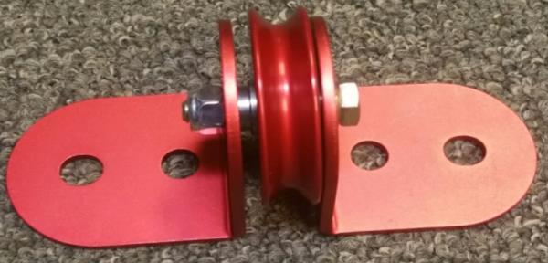
9 Helpful Photos Small Cable With Shut Off Bar Small Cable with Shut Off Donut 9
10 Helpful Photos 10


, to note where you")


11 Required Tools Electric Drill with 1/8 bit Standard Socket Set Stud Finder Tape Measure and Pencil Cable / Wire Cutters Optional: Electric Hammer Drill We recommend that you use the Storage Locator Worksheet (Appendix II), to note where you would like to install our products. You can also draw out the position / direction of your ceiling trusses, as it relates to our systems. Keeping good notes will ensure proper installation and support future installations. 11


12 Helpful Photos Mounting Tracks With Horizontal Pulleys Mounting Tracks With Down Pulleys off set 12

13 Helpful Photos Mounting Tracks With Motor Mount and Shaft Bearing 13


14 Helpful Photos Small Cable With Shut Off Bar Small Cable with Shut Off Donut 14

15 Helpful Photos 15
16 Required Tools Electric Drill with 1/8 bit Standard Socket Set Stud Finder Tape Measure and Pencil Cable / Wire Cutters Optional: Electric Hammer Drill We recommend that you use the Storage Locator Worksheet (Appendix II), to note where you would like to install our products. You can also draw out the position / direction of your ceiling trusses, as it relates to our systems. Keeping good notes will ensure proper installation and support future installations. 16


17 Part List Part Name Picture Quantity Mounting Track Coupler x4 Cross x6 Downward Pulley x4 Horizontal Pulley x6 Rail Wall Bracket Pulley X4 17


18 Part List Part Name Picture Quantity Cable Shaft and Spools x1 Bearings On Shaft (Extension kits have 3) x2 Motor and Motor Plate x1 Upper level limit Donut with cable ties x1 Motor Cover w/end cap (Optional) X1 18


19 Deck Parts List Part Name Picture Quantity Mounting Track x12 Rail Wall Bracket Pulley X4 Rail x6 Rail Wall Bracket Clamps x8 Universal Rail Connector x2 2 x 4 Grids x4 *Motor, shaft and spools not shown. **Both bearings will be already assembled on the shaft. 19


20 Hardware Kit Contents Name Picture Quantity Lag Screw Small Nut Small Carriage Bolt Small Bolt Medium Bolt Large Bolt Motor Shaft Large Nut x48 X28 X24 X24 X58 X3 X44 Rail Clamp Small Eye Bolt and Thimble Wire Clip For Securing to Eye Bolt X8 X4 X12 Washer 30 Note: Extra hardware may be included in kit. Large Bolts come already assembled in parts 20

![Tips: The direction of your ceiling outlets will [typically] indicate the direction of your trusses The location of your garage door support will indicate](/docs-images/87/95443834/images/21-3.jpg "the location and/or spacing of your trusses. or Trusses will run perpendicular to track support.")
21 1 Determine your ceiling support system. To understand your truss direction, spacing or placement, you may need to enter your attic. You may also need to consult your builder or a licensed contractor. As an additional resource, refer to Appendix I. Tips: The direction of your ceiling outlets will [typically] indicate the direction of your trusses The location of your garage door support will indicate the location and/or spacing of your trusses. or Trusses will run perpendicular to track support. In this case you can measure the screws to estimate truss spacing. Track support will be attached to a single truss 21


22 1 Continued You will need to determine the direction of your ceiling support system prior to installation, as there are 2 options: Option A: Trusses run parallel to your 8 length. Requires Approximately 90 x 78 of clear ceiling space*. OR Option B: Trusses run perpendicular to your 8 length. Requires Approximately 96 x 52 of clear ceiling space**. *Footprint including rack is approximately: 108 x 78 *Footprint including rack is approximately: 118 x 52 22
23 2 Determine what section of the garage will house your new Motorized Ceiling Storage Solution. Make sure there are no obstructions within the designated space (i.e., lights, attic door, sprinklers, etc.). If you have cabinets in your garage, make sure there is adequate clearance for doors to open. The image below represents our completed rack schematic. [This page is Option B, which trusses run perpendicular to your 8 rack length]. 96 Dashed Line: Rack Outline 52 *Footprint including rack is approximately: 118 x 52 23


.")
24 3 Measurements and instructions are provided on the following pages. Please note: the provided measurements are for the center of the mounting track (dashed line in the figure below). Four lag screws secure each mounting track into two trusses From the center of the mounting track measure 1 1/8 in each direction to pinpoint the appropriate drilling locations (shown above in the solid lined arrows). Ensure the lag screw is in the center of the truss. Refer to Appendix III for additional information regarding proper mounting. Yes! No! 24

. Continued information on following page.")
25 3 Continued When preparation is complete: installation will begin with the motor and spools. Three mounting tracks will be used in this step, two to secure the motor to the ceiling and one to secure the spools. The recommended distance is approximately 8 to the center of the motor from the end of the deck* (this allows space for the mounting of the case without impeding your storage area). Continued information on following page. *You CAN install the motor inside your storage area, if preferred, but you may lose that additional storage space. 25
26 3 Continued Included in the kit is a string with 4 thumbtacks that you may choose to use as a guide (the string forms a U shape shown below): When installing the motor mark the ceiling 8 from where you would like the edge of the deck, and 12 from the corner of the deck [view from above]. Below is the deck outline with representative marking of this location. Where these two lines intersect is representative of the center of your motor and mounting track. 26
27 3 Continued Now that we have our starting point, we will begin installation of the mounting tracks. If you are following option B installation, you will use this point to install the first mounting track. Using this point you will find the closest truss to that location. Using that truss, measure 12 from the end of the rack to the center of the truss*. You will want to pick the closest wall/fixed point to ensure that your installation is square. In our case we will say 12 from the rack is equal to 16 from our closest wall. To install the mounting tracks we will measure 1-1/8 to the left or right of this mark to pilot and secure our first lag screw. Snug the screw, but do not over tighten. From there, we will pull our measurement from the wall and ensure the center of our mounting track is 16 to the center [do this by pivoting the track on the lag you installed, if the track will not move you may have to loosen your first screw] once square, pilot and install the following 3 lag screws. All mounting tracks need to be installed into 2 separate trusses! *It is highly recommended you probe to ensure you have found the center of the truss DO NOT RELY SOLELY ON THE STUD FINDER for more information on this please see Appendix III. 27
28 Hardware Required x4 3 Continued Now that we have our first mounting track installed and squared, the second one should be installed 8 from center to center.** Remember to measure over 1-1/8 to appropriately pilot for each lag screw. *It is highly recommended you probe to ensure you have found the center of the truss DO NOT RELY SOLELY ON THE STUD FINDER for more information on this please see Appendix III. **It is vital that these mounting tracks are 8 center to center and square, as the motor will be very hard to install, or may not function properly if misaligned. 28

29 3 Continued Now that both mounting tracks are installed to support the motor, install the 3 medium bolts and washers corresponding to the slotted holes on the motor. These bolts need to be started into the mounting tracks with about 1 of thread hanging down. [If the motor and spools are already attached you can hang it as one unit, or you can remove the 3 bolts that attached the motor and spools]. The motor feet slots will slide over the bolts*. The foot with the single hole will need to be aligned and a final large bolt will prevent the motor from moving. Tighten all four bolts completely. Key: Make sure to place washer on screw and partially secure into the mounting track Hardware Required x4 x4 Slotted hole x 3 Closed hole x 1 29 *Please note: the motor is heavy and although one person can install it, it may require additional help.

30 Hardware Required x4 x4 x8 3 Continued Now that the motor has been successfully installed, the easiest method to install the spools is to insert the 3 small driveshaft bolts (if disconnected), connecting the motor and spools. Once this unit is connected and the bolts are tight, spin the bearing so the flat edge is toward the ceiling. Slide the mounting track and flat cross between the bearing and ceiling. Align the holes of the bearing with the cross and mounting track with the ability to secure to the ceiling with lag screws, into the same 2 trusses as your motor. Repeat this step for the second bearing, placing it close to the last spool. Image represents how to secure the bearings to the mounting track. The shaft and spools have been omitted to provide a clear view. Please note: this image is representative of proper installation only, your bearing may use different holes and fall in a different location on the track, every installation is different. 30
31 4 Now that the motor and shaft have been successfully installed, we will continue with the pulley system. To find out starting point we will find the nearest wall or fixed point. We need to find the centerline of each spool [there are 4 total spools]. We will label them A,B,C and D for simplicity. Please write your measurements on this page; you will need them for the following steps. Continued on next page. 31
32 5 Now that we have the measurements to the center of each spool, installation of the four center mounting tracks should be simple. The measurement to the center equates to the inside lag screw position. Please see image below. The centerline of the motor is used for correctly spacing the mounting tracks. From the center of the motor the distance should be roughly 83 this 83 is used as a guide, you will need to find the 2 trusses surrounding the 83 mark. Image below shows installation of Mounting track A Continued on next page. 32
33 5 Continued Now that we have the measurements to the center of each spool, installation of the four center mounting tracks should be simple. The measurement to the center equates to the inside lag screw position. Please see image below. Installation of mounting track B Continued on next page. 33
34 5 Continued Now that we have the measurements to the center of each spool, installation of the four center mounting tracks should be simple. The measurement to the center equates to the inside lag screw position. Please see image below. Installation of mounting track C Continued on next page. 34
35 5 Continued Now that we have the measurements to the center of each spool, installation of the four center mounting tracks should be simple. The measurement to the center equates to the inside lag screw position. Please see image below. Installation of mounting track D Continued on next page. 35
36 5 Continued Now that we have all 4 of the center mounting tracks installed, we will continue by installing the remaining 4 tracks. From the centerline (center of the middle two spools). From the centerline we need to install the first 2 tracks using the same 2 trusses, 50 apart center to center, or 25 to the center of the track from the centerline. Continued on next page
37 Hardware Required X4 x4 5 Continued Before we can determine the location of the final 2 mounting tracks we must install the first set of pulleys. To install the horizontal pulleys: one large bolt is inserted through the clip and pulley into the mounting track. To install the vertical pulley 2 medium bolts and washers are installed into the mounting track through the cross. Please see images below. Distance should be approximately 83 from center of spools to the groove in the rear of the horizontal pulley. Vertical pulleys should be installed so they are in line with horizontal pulleys. Please install the only the four pulleys shown. Continued on next page. 37
38 5 Continued The center two horizontal pulleys are installed closer to the motor, as to not interfere with the others. Their position on the mounting track is not vital. Ensure the cable guides are pointed in the same direction as the image below. [Cable guides are the C shaped piece bolted to the pulley]. The outside 2 horizontal pulleys should be aligned with the position of the center 2 spools. Continued on next page. New Part 38
39 Now that all the rear pulleys have been installed, the final 2 mounting tracks can be set. They need to be installed so that 53 from the rear vertical pulley falls on the track, between 2 trusses, each is then 25 to center from the centerline. Please refer to the image below. Continued on next page. 5 Continued New Part
40 Hardware Required 5 Continued Now that the final 2 tracks have been installed the final 2 vertical pulleys need to be installed. These should be as close to 53 from the rear vertical pulleys as possible, this number provides the best support for the 4x8 platform. X4 X4 40
41 6 Now that you have the ceiling mounts installed, you will need to remove the tape from the spools and plug in the motor. While pulling on the cables slowly release the cables until you have only one full wrap on the spools remaining, all four spools should always have one full wrap of cable, do not run below this point. With all of the tape removed, you need to run the cable through the pulleys as the schematic below illustrates. Once through the vertical pulleys, you should have a lot of excess suspended. Note. We strongly recommend NOT using a knife to remove tape as it could damage the cable coating. 41
42 Hardware Required: x24 x24 7 To assemble the sides of the platform, begin by laying two 4 Rails end to end. Use Universal Rail Connector, along with twelve Small Carriage Bolts and twelve Small Nuts, to join the two 4 Rails. Repeat with other two 4 Rails and second Universal Rail Connector. Note: Bolts on the bottom should have heads facing up (this will allow the grids to sit flat). 30 Outside Inside Completely Tighten both sets to creating the two 8 lengths. 42

43 Hardware Required: x4 x4 11 To assemble the end of the platform, begin by laying two 8 Rails side by side. Use 2 medium bolts and large nuts, to join each the two 4 Rails to the 8 sections to create one continuous perimeter. Drop one Small Bolt (C) into each end of both 8 rails Secure the 4 rail under both 8 sections Leave bolts loose, until grids have been installed. 43


44 Hardware Required: x16 x16 12 To complete the platform install the 4 grids, as shown below. Using 4 small bolts and 4 large nuts, secure each grid to the 8 rails. Stiffeners on underside of grid. Holes align and bolt to rails for safety. The grids may need to be rotated to align holes, but stiffeners should always remain underneath grid for support. 44
45 12 The cable needs to be first strung through each block. Note. Detachment option is show here. If you did not purchase this option run cable through pulley of rail wall bracket pulley. 45


46 12 The cable needs to be first strung through each block. Note. Detachment option is show here. If you did not purchase this option run cable through pulley of rail wall bracket pulley. 46

47 Hardware Required: x12 12 Continued To complete the installation, you need to ensure the rack is level. Raise or lower each cable, ensuring there is tension on the cable at all times. Use three Wire Clips per cable to secure each cable in the position where the rack is perfectly level. Please reference the image below to ensure your clips are installed appropriately. Ensure all of the cables are properly in the groove of each pulley, this is a vital step! Before running the unit up or down all cables should be visually checked. Cables always need to have tension to prevent them from jumping their intended course, this unit is not designed to go to the ground/floor. Taking the weight off the cables will result in incorrect operation. The 4 Rail brackets with eye bolts should be secured to the rail as shown below (grids omitted for clarity). Using a small nut for the upper clamp and a medium bolt with large nut for the lower part of the rail. These should be installed directly below the cable for optimum performance. When all connections are tight and the rack is level, you will need to cut the excess cable below the last wire clip. Do Not Cut the cable on the side going to the rack, just the loose end. 47
48 SPECIAL NOTES Ensure all of the cables are properly in the groove of each pulley, this is a vital step! Before running the unit up or down all cables should be visually checked. Cables always need to have tension to prevent them from jumping their intended course, this unit is not designed to go to the ground/floor. Taking the weight off the cables will result in incorrect operation. 48

49 Motor Cover Installation The motor cover is attached to the Motor Plate Mounting Tracks and goes around the motor. The motor cover has slotted holes to bolt into the mounting tracks. The end plate has an U slot that can be attached to the mounting track or with a drywall screw into the ceiling. The end cap goes on the opposite side of the motor. The hole is for the end of the shaft. The loop at the top can be secured to a mounting track or using a screw into the dry wall 49


50 Upper Limit Stop Installation With Motor Cover Without Motor Cover The red donut pushes on the silver actuator bar and stops the motor. This keeps your items from hitting the ceiling. You set the cable ties and donut where you want the motor to stop. Make sure to tighten them fully. Set small cable ties at the height of the ceiling stop position. With a motor cover, the donut sits inside the cover. The square washers are to keep the cable taught. The cable ties will go inside the motor cover and grab the donut. 50


51 Appendix V Accessory Options Bike Adapter 18 x 36 Steel Wall Shelf Wood Shelf Liner Ladder Hanger All Purpose/Bike Hook 51
52 Congratulations! Stand back and admire your completed PowerRax Motorized Storage Solution. Motorized Installation Option B Detachment Kit with Motor Cover Now you can load your system. Refer to Appendix V for additional accessory options. 52


53 There are 4 standard type of roof structures: 1. Living Space above the garage area. 2. Flat roofs. 3. Hip / Truss roofs. 4. Traditional Gable roofs. Living Space Above Garage Appendix I Understanding Your Ceiling Support Systems Flat Roof Structure Hip in roof structure or Truss roof Traditional Gable It is important to identify the type of roof structure you have, to start the process of installation. Once you identify the type of roof structure you have, you can understand the type of construction your have in your ceiling. We will attempt to demonstrate the type of ceiling or truss systems but these types may vary. If you have any questions on the type of roof structure you have, we recommend contacting your builder, viewing your ceiling trusses via your attic access or contacting a qualified representative to help you. 53

54 Appendix II Storage Locator Worksheet 54


55 Appendix III Proper Mounting It is recommended to use a stud finder and physically inspect your crawl space to locate your truss direction. You can also make note of any electrical, plumbing or gas lines that may be around your truss system. Always install the lag screws directly into the center of a truss. With appropriate installation, you should never encounter utility lines. We recommend probing to find the edges of your truss. This is the most reliable method of finding the center of your truss and ensures proper installation of the lag screws. Because our lag screws are designed to be contained inside of solid wood trusses, they are 3 in length. If you find that you have pre-fabricated wood trusses such as TGI s, we recommend that you slowly tighten your lag screws into the mounting track. Some pre-fabricated trusses are thin, and your lag screws may penetrate the back side. If you cannot view your trusses due to a living space being above your garage, you can purchase 2 ½ steel lag screws to replace the 3 lag screws that are provided in your hardware kit. In every situation, it is best to consult with your builder or a professional to help with your project. 55


56 Appendix IV Need Installation Help? Visit to locate your nearest installer or watch our detailed installation video. Some homeowners prefer to stream this video in their garage while installing our products. While our installation videos provide a high level of detail, you must still thoroughly read through this installation guide prior to starting your project.
48 in. X 96 in. 500 Pound Capacity Motorized Overhead Storage Unit Installation Guide [OPTION B] MODEL # PRM4X8 Patent Pending
![48 in. X 96 in. 500 Pound Capacity Motorized Overhead Storage Unit Installation Guide [OPTION B] MODEL # PRM4X8 Patent Pending](/thumbs/81/83353561.jpg "48 in. X 96 in. 500 Pound Capacity Motorized Overhead Storage Unit Installation Guide [OPTION B] MODEL # PRM4X8 Patent Pending") 48 in. X 96 in. 500 Pound Capacity Motorized Overhead Storage Unit Installation Guide [OPTION B] MODEL # PRM4X8 Patent Pending 1 Table of Contents Table of Contents PAGES Installation Support 3 Safety
48 in. X 96 in. 500 Pound Capacity Motorized Overhead Storage Unit Installation Guide [OPTION B] MODEL # PRM4X8 Patent Pending 1 Table of Contents Table of Contents PAGES Installation Support 3 Safety
48 in. X 96 in. 500 Pound Capacity Motorized Overhead Storage Unit Option A
 48 in. X 96 in. 500 Pound Capacity Motorized Overhead Storage Unit Option A MODEL # PRM4X8 Patent Pending 1 Table of Contents Table of Contents PAGES Installation Support 3 Safety Information 4-5 Required
30 wide track Adjustable Tire Rack
 30 wide track Adjustable Tire Rack MODEL # SRTRB Patent Pending 1 Installation Support Please Do Not Return This Product To The Store! 1-877-717-RACK (7225) info@strongracks.com If there are any missing
MONKEY BARS OVERHEAD RACK INSTALLATION
 MONKEY BARS OVERHEAD RACK INSTALLATION Thank you for purchasing the New Monkey Bars Overhead storage rack. The most innovative overhead rack on the market WARNING THE PROPER INSTALLATION OF THIS STORAGE
Laminate Cabinet Installation Instructions
 Laminate Cabinet Installation Instructions www.easygaragestorage.com/installation How To Use These Instructions Thank you for your purchase! Please read each step of this manual thoroughly to ensure proper
Assembly Instructions
 Thank You For Purchasing The Best Overhead Storage Rack Assembly Instructions Overhead Storage Rack 8 x 4 8 x 3 8 x 2 6 x 4 6 x 3 6 x 2 4 x 4 Two 8 x4 Racks Pictured P.O. Box 714, El Cerrito, CA 94530
INSTALLATION INSTRUCTIONS
 INSTALLATION INSTRUCTIONS Universal Low Profile Flat Mount Model: U.S. Toll Free: 1-866-752-6271 Outside N. America: 1-503-748-5799 E-mail: ts@planar.com FRANCE Phone: +33 5 6378 3810 E-mail: emeats@planar.com
GroundControl. Follow instructions contained in this manual. Incorrect installation could result in serious injury or damage to property.
 GroundControl TM use supplied hardware Use only hardware supplied in your GroundControl kit or supplied by an authorized YAKIMA dealer. Use of unauthorized parts in the GroundControl system could result
INSTALLATION INSTRUCTIONS
 INSTALLATION INSTRUCTIONS Universal Low Profile Tilt Mount Model: U.S. Toll Free: 1-866-752-6271 Outside N. America: 1-503-748-5799 E-mail: ts@planar.com FRANCE Phone: +33 5 6378 3810 E-mail: emeats@planar.com
The Festival Assembly Instructions
 The Festival Assembly Instructions Toll Free: 866.768.8465 Hours: 9-5 Monday-Friday EST www.homeplacestructures.com Package ships as shown CONTACT INFORMATION: HomePlace Structures 301 Commerce Drive New
MM340 Installation Instructions IMPORTANT SAFETY INSTRUCTIONS - SAVE THESE INSTRUCTIONS
 MM30 Installation Instructions IMPORTANT SAFETY INSTRUCTIONS - SAVE THESE INSTRUCTIONS Please read this entire manual before you begin. Do not unpack any contents until you verify all requirements on PAGE.
MPA-9000 Universal Ceiling Projector Mount Kit
 I N S T R U C T I O N M A N U A L Universal Ceiling Projector Mount Kit The Universal Ceiling Projector Mount provides a unique, simplified method of ceiling mounting your inverted projector. This low
GearBoss II High Density storage
 Assembly/Owner s Manual GearBoss II High Density storage contents Safety...........................................2 General......................................2 Installation...................................2
MM540 Installation Instructions IMPORTANT SAFETY INSTRUCTIONS - SAVE THESE INSTRUCTIONS
 MM50 Installation Instructions IMPORTANT SAFETY INSTRUCTIONS - SAVE THESE INSTRUCTIONS Please read this entire manual before you begin. Do not unpack any contents until you verify all requirements on PAGE.
Contractors Rack Assembly and Installation Instructions
 Part # 18601 & 16601 Contractors Rack Assembly and Installation Instructions 4751 Littlejohn St. Unit A, Baldwin Park, CA 91706 Page 1 of 12 11/13/08 Thank you for purchasing the Paramount Restyling Contractors
MM750 Installation Instructions
 MM750 Installation Instructions IMPORTANT SAFETY INSTRUCTIONS - SAVE THESE INSTRUCTIONS Please read this entire manual before you begin. Do not unpack any contents until you verify all requirements on
INSTALLATION TORSION SPRING FRONT OR REAR MOUNT LOW HEADROOM. 1 Cutting Vertical Track. 2 Fully Adjustable Jamb Brackets
 TORSION SPRING FRONT OR REAR MOUNT LOW HEADROOM Wayne Dalton, a division of Overhead Door Corporation P.O. Box 67, Mt. Hope, OH., 44660 Supplemental insert Copyright 2015 Wayne Dalton, a division of Part
Hardware Box 1 1/4 Diameter x 3/4 Long Bolts 24 1/4 Nylon Lock Nut 24 1/4 Diameter x 3 Long Lag Bolt 8 1/4 Washers 56
 Warning: Excessive weight hazard! Use two or more people to move, assemble or install overhead rack to avoid back or other injury. Do not leave children unattended near overhead rack. High risk of injury
OVER THE RANGE MICROWAVE OVEN INSTALLATION INSTRUCTIONS
 OVER THE RANGE MICROWAVE OVEN INSTALLATION INSTRUCTIONS Please read and save these installation instructions. MODEL NO.: DOTR12CWIV/DOTR12CBIV P/N: 3828W5U0202 YOUR SAFETY FIRST Read this entire manual
TITAN INDUSTRIAL RACK 6-FOOT TALL / 4-SHELF
 TITAN INDUSTRIAL RACK 6-FOOT TALL / 4-SHELF DXST10000 IMPORTANT: Please read this manual carefully before assembling this storage rack and save it for reference INSTRUCTION MANUAL 3 TABLE OF CONTENTS
19 to 39 TV WALL MOUNT - FULL MOTION
 19 to 39 TV WALL MOUNT - FULL MOTION RF-HTVMMAB For wood-stud and concrete wall installations Safety information and specifications...2 Tools needed...2 Package contents...3 Installation instructions...5
400A 40113V, 401A 40120V, & 401AL 40120VL ALUMINUM VERTICAL 4000 LB LIFT INCLUDES SCREW LEG ASSEMBLY INSTRUCTIONS
 12/11/07 PAGE 1 OF 12 400A 40113V, 401A 40120V, & 401AL 40120VL ALUMINUM VERTICAL 4000 LB LIFT INCLUDES SCREW LEG ASSEMBLY INSTRUCTIONS Thank you for purchasing our product! *Please read these instructions
Wall Mount Assembly and Mounting Guide (55 /84 )
") Microsoft Surface Hub Wall Mount Assembly and Mounting Guide (55 /84 ) For mounting on a wall with wood studs These instructions assume wood-stud wall construction with 2-by-4 studs spaced 16 inches apart,
Microsoft Surface Hub Wall Mount Assembly and Mounting Guide (55 /84 ) For mounting on a wall with wood studs These instructions assume wood-stud wall construction with 2-by-4 studs spaced 16 inches apart,
TP4463. ASSeMBly INSTruCTIONS FLAT PANEL TV MOUNTING SYSTEM OPTION 1 OPTION 2 OPTION 3
 TP63 FLAT PANEL TV MOUNTING SYSTEM OPTION 1 OPTION 2 OPTION 3 Flat Panel TV Stand Stand with TV Mounting System Stand with Wall Mount ASSeMBly INSTruCTIONS for your safety, please follow these precautions:!
RESIDENTIAL MOTORIZED STORAGE UNIT
 BY V-BRO PRODUCTS RESIDENTIAL MOTORIZED STORAGE UNIT Model: GGR220 INSTALLATION AND OPERATING INSTRUCTIONS Distributed Exclusively by V-BRO PRODUCTS For technical questions and replacement parts, please
INSTALLATION INSTRUCTIONS
 CREATING POSITIVE CUSTOMER EXPERIENCES INSTALLATION INSTRUCTIONS Universal Low Profile Tilt Mount for 42 to 63 Flat Panels NORTH AMERICA 3130 East Miraloma Avenue Anaheim, CA 92806 USA USA and Canada Phone:
EmagiKit. Privacy Pod Plus. Quiet. Easy. Affordable. INSTRUCTIONS ASSEMBLY
 EmagiKit Privacy Pod Plus Quiet. Easy. Affordable. INSTRUCTIONS ASSEMBLY DIMENSIONS AND COMPONENTS 47 47 Ceiling Unit 2-B 2-L 2-R Glass Door Corner Trim Door Handle 90 Adjustable Height Work Surface 1-B
Ram Promaster Rack. Installation instructions for
 Installation instructions for Ram Promaster Rack MyGlassTruck.com 200 Acorn Road LOCAL 856-595-9069 WEB www.myglasstruck.com Glassboro, NJ 08028 FAX 856-863-1480 1-844-364-4022 Version 1.0 November 2015
U.S. Rack, Inc Falcon Drive, Madera, CA APR17 INSTALLATION AND USE INSTRUCTIONS for SIDE-MOUNT LADDER RACK
 U.S. Rack, Inc. 2850 Falcon Drive, Madera, CA 93637 15APR17 INSTALLATION AND USE INSTRUCTIONS for SIDE-MOUNT LADDER RACK WARNING: Do NOT attempt to install or use this rack without following all instructions.
MSP-WRTIDSKY1 Light Weight Suspended Ceiling Kit for use with Island Display Skybox
 INSTALLATION INSTRUCTIONS MSP-WRTIDSKY1 Light Weight Suspended Ceiling Kit for use with Island Display Skybox The MSP-WRTIDSKY1 Light Weight Suspended Ceiling Kit provides a sturdy support for LCD displays
Lange Crank Hoist-a-top Assembly Instructions
 Lange Crank Hoist-a-top Assembly Instructions Installation Time: 1-4 Hours depending on skill level Tools Required: Cordless Drill Level Stud Finder Ratcheting wrench 9/16 socket or wrench 11/16 socket
Worktop INDEX eight Capacity Unpacking
 Pro.0 Series Warning: Excessive weight hazard! Use two or more people to move, assemble or install cabinets and locker to avoid back injury. Do not leave children unattended near cabinets. High risk of
Baby Grande or Grande Crank Shade with Cables and Housing Installation Instructions
 Baby Grande or Grande Crank Shade with Cables and Housing Installation Instructions Tools Needed Drill 3/8 Metal Drill Bit Screwdriver (Flat & Phillips) Measuring Tape Pencil 4 Level Plumb Line ¼ Masonry
MantelMount. TM1A Installation Instructions IMPORTANT SAFETY INSTRUCTIONS - SAVE THESE INSTRUCTIONS
 MantelMount TMA Installation Instructions IMPORTANT SAFETY INSTRUCTIONS - SAVE THESE INSTRUCTIONS TM Thank you for choosing the MantelMount television wall mount. Please read this entire manual before
RLP Flat Track Hardware sliding door hardware/ barn door track
 Page 1 of 9 Installation Suggestions for: RLP Flat Track Hardware sliding door hardware/ barn door track Read these instructions to end before starting installation or ordering hardware. Reclaimed Lumber
RESIDENTIAL MOTORIZED PLATFORM LIFT SYSTEM
 BY V-BRO PRODUCTS RESIDENTIAL MOTORIZED PLATFORM LIFT SYSTEM Model: GG 22 INSTALLATION AND OPERATING INSTRUCTIONS Distributed Exclusively by V-BRO PRODUCTS www.garagegator.com For technical questions and
FOR PROFESSIONAL GARAGE DOOR INSTALLERS
 Composite Garage Doors Installation Instructions FOR PROFESSIONAL GARAGE DOOR INSTALLERS Tools required Screwdriver Claw Hammer Locking Pliers Power Drill Level with a 3/32" Drill Bit Utility Knife 9/16",
Baby Grande or Grande Crank Shade with Cables and Housing Installation Instructions
 Baby Grande or Grande Crank Shade with Cables and Housing Installation Instructions Tools Needed Drill 3/8 Metal Drill Bit Screwdriver (Flat & Phillips) Measuring Tape Pencil 4 Level Plumb Line ¼ Masonry
Desk/Wall-Mount Rack
 Desk/Wall-Mount Rack Patent(s) Pending Installation Instructions Post P/N: 119-1752 119-1781 119-1782 119-4014 Frame P/N: 119-1591 119-1754 119-1755 Kit Contents (2) Frames (4) Posts Assembly Hardware
RLP Mini Low Profile V Track Hardware sliding door hardware/ barn door track
 Page 1 of 9 Installation Suggestions for: RLP Mini Low Profile V Track Hardware sliding door hardware/ barn door track Read these instructions to end before starting installation or ordering hardware.
Installation Instruction
 Tools Needed for Assembly Stud finder (for wood stud wall) Pencil Mark Electric drill Wood Stud Wall Installation Step 1. Locate the Wood Studs Installation Instruction Drill bit (for wood stud wall) Masonry
Dual Arm Tilt LCD Mount
 Installation Manual model # 51324 M o u n t i n g S y s t e m s Dual Arm Tilt LCD Mount Fits Displays 13 to 32 Supports Up to 50 lbs (23 kgs) Projection from Wall from 3 to 17 Meets VESA Standards 50/75/100,
CMA-455 Suspended Ceiling-Tile Reinforcing Kit
 INSTALLATION INSTRUCTIONS CMA-455 Suspended Ceiling-Tile Reinforcing Kit The provides a sturdy support for LCD/DLP hanging brackets (and certain other products) when installing these products in a suspended
JEEP JK ( 5 DOOR ) SLIMLINE II - FULL TRAY EXTREME RACK KIT
 SLIMLINE II - FULL TRAY EXTREME RACK KIT") JEEP JK ( 5 DOOR ) SLIMLINE II - FULL TRAY EXTREME RACK KIT FAJK001 / KRJW014T INSTALL TIME: 2.5 Hours NOTE: Your Jeep JK (5 Door) Extreme Roof Rack Kit consists of four boxes. (1) the Tray, (2) the Roll
JEEP JK ( 5 DOOR ) SLIMLINE II - FULL TRAY EXTREME RACK KIT FAJK001 / KRJW014T INSTALL TIME: 2.5 Hours NOTE: Your Jeep JK (5 Door) Extreme Roof Rack Kit consists of four boxes. (1) the Tray, (2) the Roll
INS T A L L A TIO N INS T R U C TIO N S. Ceiling Mount Track System
 Ceiling Mount Track System 10.26.2016 Specifications Ceiling Post: Unassembled 2-7/8 Assembled 1-11/16 7/8 7-9/16 5-7/8 3/8 2 Tubes 1/2 2-3/8 5 Parts and Tools Tools Needed Tape Measure Pencil Drill with
INSTALLATION MANUAL PBL-UMP
 INSTALLATION MANUAL PBL-UMP Table of Contents Warning Statements... 4 Parts List... 5 Installation Tools... 5 Features... 7 Projector Preparation... 8 Bracket Installation... 10 Leveling the Mounting Bracket...
Universal flat-panel mount
 I N S T A L L A T I O N M A N U A L Universal flat-panel mount www.christiedigital.com PM 2004/ REV 02 Contents - Assembly drawing - Fine tune tilt adjustments - Parts list - Installing the adapter plate
/B INSTALLATION MANUAL
 02-001127/B INSTALLATION MANUAL LEVITATION TV MOUNT UNIVERSAL TV MOUNT FOR 55"-75" PANEL TV'S 100 POUND MAXIMUM WEIGHT IMPORTANT SAFETY INSTRUCTIONS - SAVE THESE INSTRUCTIONS - PLEASE READ ENTIRE MANUAL
QLF215 INSTRUCTION MANUAL
 QLF215 INSTRUCTION MANUAL We ll Make It Stress-Free If you have any questions along the way, just give us a call. 1-800-359-5520. We re ready to help! 1 2 3 IMPORTANT SAFETY INSTRUCTIONS SAVE THESE INSTRUCTIONS
SAM. Model: STV-C65 LCD Mobile Visualized Stand Instruction Manual. Weight Capacity: 1251bs / 56.7kg Suits LCD Flat Panel Display: 42"-55" Page 20
 SAM Model: STV-C65 LCD Mobile Visualized Stand Instruction Manual Weight Capacity: 1251bs / 56.7kg Suits LCD Flat Panel Display: 42"-55" 20 Step 6 LCD Mobile Lift Stand Model: STV-C65 Cable management
Octagon Vinyl Gazebo Assembly Instructions
 Octagon Vinyl Gazebo Assembly Instructions For 10 & 12 Models Toll Free: 866.768.8465 Hours: 9-5 Monday-Friday EST www.homeplacestructures.com Package ships as shown revised 04/29/09 Vinyl Gazebo Assembly
PWM-T210 Installation Instructions UNIVERSAL FLAT PANEL MOUNT
 UNIVERSAL FLAT PANEL MOUNT IN-PWMT210.R0 TABLE OF CONTENTS Warning Statements 3 Parts List 4 Installation Tools 4 Locating the Center of the 5 Mounting Bracket Positioning 5 Securing the Mounting Brackets
INSTALLATION INSTRUCTIONS
 INSTALLATION INSTRUCTIONS P4263F Universal Low Profi le Flat Mount for 42 to 63 Flat Panels NORTH AMERICA 3130 East Miraloma Avenue Anaheim, CA 92806 USA USA and Canada Phone: 1.800.368.9700 Fax: 1.800.832.4888
DX-TVMLPTB03. Low-Profile TV Wall Mount ASSEMBLY GUIDE. For either wood-stud or concrete wall installations
 ASSEMBLY GUIDE DX-TVMLPTB03 Low-Profile TV Wall Mount For either wood-stud or concrete wall installations Safety information and specifications...2 Tools needed...........................3 Package contents......................3
Closet Carousel Installation Instructions. Models TKA 5 Through TKA 14 Equipped with Footswitch Controls
 Tools Required: Phillips Screwdriver (#2) Adjustable Wrench Level Tape Measure Utility Knife Electric Drill Drill Bits for Anchors Ladder (4 foot) Models TKA 5 Through TKA 14 Equipped with Footswitch Controls
TITAN INDUSTRIAL RACK 4-FOOT TALL / 3-SHELF
 TITAN INDUSTRIAL RACK 4-FOOT TALL / 3-SHELF DXST4500 IMPORTANT: Please read this manual carefully before assembling this storage rack and save it for reference INSTRUCTION MANUAL 3 TABLE OF CONTENTS TECHNICAL
/A INSTALLATION MANUAL
 02-001118/A INSTALLATION MANUAL LEVITATION TV MOUNT UNIVERSAL TV MOUNT FOR 55"-85" PANEL TV'S 125 POUND MAXIMUM WEIGHT IMPORTANT SAFETY INSTRUCTIONS - SAVE THESE INSTRUCTIONS - PLEASE READ ENTIRE MANUAL
Octagon Vinyl Gazebo Assembly Instructions For 10 & 12 Models
 Octagon Vinyl Gazebo Assembly Instructions For 10 & 12 Models Toll Free: 866.768.8465 Hours: 9-5 Monday-Friday EST www.homeplacestructures.com Package ships as shown revised 04/29/09 Vinyl Gazebo Assembly
RESIDENTIAL MOTORIZED STORAGE UNIT
 888-GATOR-08 www.garagegator.com BY V-BRO PRODUCTS RESIDENTIAL MOTORIZED STORAGE UNIT Model:GG8220 INSTALLATION, OPERATING, AND SAFETY INSTRUCTIONS Distributed Exclusively by: V- BRO PRODUCTS, LLC www.garagegator.com
US RACK, Inc Falcon Drive, Madera, CA
 US RACK, Inc - 2850 Falcon Drive, Madera, CA 93637-559-661-3050 INSTALLATION AND USE INSTRUCTIONS for Long-John Extension Ladder Rack WARNING: Do NOT attempt to install or use this rack without following
Installation Manual Flat Track Series
 Manual Flat Track Series Contents Safety...1 Parts...2 Hardware.......................................... 2 Tools Required..................................... 4.............................................
WOVEN WOOD SHADES Corded, Continuous Cord Loop or Upended
 WOVEN WOOD SHADES Corded, Continuous Cord Loop or Upended GETTING STARTED HARDWARE INFORMATION A few simple tools are required: The hardware you received with your product are REQUIRED for proper installation.
GB-AVSTOR5 Ceiling Equipment Storage Box with Pipe Coupler
 Ceiling Equipment Storage Box with Pipe Coupler INSTALLATION INSTRUCTIONS CREATING POSITIVE CUSTOMER EXPERIENCES 9534-500-021-00 Contents Weight Limit... 2 Warning Statements... 2 Installation Tools...
ASSEMBLY INSTRUCTIONS TALL CABINET - MODEL CS30
 ASSEMLY INSTRUCTIONS TALL CAINET - MOEL CS30 To avoid SERIOUS INJURY or AMAGE to personal belongings: O NOT overload the cabinet or the shelves, maximum weight limit for feet or caster installation is
INSTALL INSTRUCTIONS WELCOME TO THE NEWAGE PERFORMANCE CABINETRY SERIES NEWAGE STEEL WELDED CABINETRY
 NEWAGE STEEL WELDED CABINETRY WELCOME TO THE NEWAGE PERFORMANCE CABINETRY SERIES ALL CABINETS MUST BE MOUNTED TO STUDS ON A SECURE WALL, AS PER THESE INSTRUCTIONS. FAILURE TO DO SO MAY RESULT IN SERIOUS
INSTALLATION MANUAL SFM3
 INSTALLATION MANUAL SFM3 Sony Electronics, Inc. 16540 West Bernardo Drive San Diego, CA 92127 www.sony.com IN-SFM3.R0 Table of Contents WARNING STATEMENTS...- 3 - PARTS LIST...- 4 - INSTALLATION TOOLS...-
Powered by. For further installation assistance: prxperformance.com/pages/murphy-rack
 Powered by The 90 Fold-in Murphy Rack is made by the creators of the original Profile Folding Rack at PRx Performance and is Patent Pending. An up-to-date record of patents and patent pending items can
SUT-1000CLC ASSEMBLY REQUIREMENTS
 SUT-1000CLC Torque wrench, carpenters square, wire cutters, Phillips screwdriver, 7/16, 9/16, and 3/4 combination wrenches, ratchet, 9/16, 3/4, 13/16, and 7/8 sockets. ASSEMBLY REQUIREMENTS *Torque all
Fixed Wall Arm. Installation Guide. Part number Rev E 2012 PolyVision Corporation All rights reserved
 Fixed Wall Arm Installation Guide Part number 2002003-001 Rev E 2012 PolyVision Corporation All rights reserved Table of contents Important Safety Instructions... 3 Overview... 4 Important considerations...
SINGLE TRACK BYPASS (patent pending) barn door hardware
 barn door hardware") SINGLE TRACK BYPASS (patent pending) barn door hardware Installation Manual What is included in your kit: Part number Part name Quantity 1 Inner door hanger 2 2 Outer door hanger 2 3 5/16 x 1.5 lag bolts
SINGLE TRACK BYPASS (patent pending) barn door hardware Installation Manual What is included in your kit: Part number Part name Quantity 1 Inner door hanger 2 2 Outer door hanger 2 3 5/16 x 1.5 lag bolts
ATLANTIS RAIL Contact Information
 ATLANTIS RAIL Contact Information Customer Service (800) 541-6829 (508) 732-9191 Spectrum System Installation Instructions Atlantis Rail s Spectrum System is an easy to install, universal cable railing
Tilting Flat Panel Wall Mount Installation Guide
 Tilting Flat Panel Wall Mount Installation Guide Model: A580TM Easy installation Built-in level for easy positioning Safety bolts lock the TV on the mount Easy to adjust tilt angles: +5 to -15 degrees
Phone #: (360) Online Tech Support: Web:
 Online Tech Support: Web:") Phone #: (360) 734-3482 Online Tech Support: tech-support@shopfox.biz Web: www.shopfox.biz Your new Model D2058A Super-Heavy Duty Mobile Base () is designed to give you a stable and mobile platform upon
Phone #: (360) 734-3482 Online Tech Support: tech-support@shopfox.biz Web: www.shopfox.biz Your new Model D2058A Super-Heavy Duty Mobile Base () is designed to give you a stable and mobile platform upon
HONEYCOMB SHADES with Continuous Cord Loop
 HONEYCOMB SHADES with Continuous Cord Loop GETTING STARTED BRACKET INFORMATION A few simple tools are required: The brackets you received with your product are REQUIRED for proper installation. Brackets
Performance 2.0 Series
 Performance. Series Warning: Excessive weight hazard! Warning: Excessive weight hazard! Use two or more people to move, assemble, or install cabinets and locker to avoid back injury. Do not leave children
1. VERIFY ALL COMPONENTS
 R INSTALLATION INSTRUCTIONS RAGNAR+ODEN FACE MOUNT, BYPASSING. VERIFY ALL COMPONENTS BASE KIT Track stand-offs Front trolley kit * Rear trolley kit * Allen keys Track fastener kit - wood - Bottom guide
LCD DISPLAY MOUNT
 I N S T A L L A T I O N M A N U A L 38-804769-01 LCD DISPLAY MOUNT WWW.CHRISTIEDIGITAL.COM Contents - Assembly drawing - Securing the bottom wall plate - Fine tune adjustments - Marking the top plate mounting
JEEP JK ( 5 DOOR ) SLIMLINE II - FULL TRAY EXTREME RACK KIT
 SLIMLINE II - FULL TRAY EXTREME RACK KIT") JEEP JK ( 5 DOOR ) SLIMLINE II - FULL TRAY EXTREME RACK KIT FAJK002 / KRJW014T INSTALL TIME: 5 Hours NOTE: Your Jeep JK (5 Door) Extreme Roof Rack Kit consists of four boxes. (1) the Tray, (2) the Roll
JEEP JK ( 5 DOOR ) SLIMLINE II - FULL TRAY EXTREME RACK KIT FAJK002 / KRJW014T INSTALL TIME: 5 Hours NOTE: Your Jeep JK (5 Door) Extreme Roof Rack Kit consists of four boxes. (1) the Tray, (2) the Roll
southpaw enterprises, inc.
 Store these instructions in a safe place or with the enclosed maintenance checklist In-FUN-ity Climbing System Assembly Examples This example sheet is intended to supplement the instruction sheets that
MANUAL e130. Wallstation
 MANUAL 07.29.13 e130 Wallstation The Enovate Medical e130 Wallstation was designed to set a new standard in quality. Enovate Medical s goal is to provide a wallstation that is ready for years of use,
Low Headroom Rear Mount TorqueMaster
 Low Headroom Rear Mount Supplemental Instruction Insert This supplemental installation instruction is to be used as a supplement to the main Installation Instruction and Owner s Manual provided with the
TV WALL MOUNT ASSEMBLY GUIDE RF-TVMLPT01V2
 TV WALL MOUNT RF-TVMLPT01V2 For wood-stud and concrete wall installations Safety information and specifications...2 Tools needed...2 Package contents...3 Installation instructions...4 ASSEMBLY GUIDE Before
Tools Needed Hardware Provided (per shade) Hardware Needed
 Hardware Needed") Baby Grande or Grande Motorized (XQ5 Premium) Shade with Cables and Housing Installation Instructions Tools Needed Hardware Provided (per shade) Hardware Needed Drill 3/8 Metal Drill Bit Measuring Tape
Baby Grande or Grande Motorized (XQ5 Premium) Shade with Cables and Housing Installation Instructions Tools Needed Hardware Provided (per shade) Hardware Needed Drill 3/8 Metal Drill Bit Measuring Tape
Installation and Assembly - Universal Articulating Swivel Double-Arm for 42" - 60" Plasma Screens
 Installation and Assembly - Universal Articulating Swivel Double-Arm for 42" - 60" Plasma Screens Models: PLAV 70-UNL, PLAV 70-UNL-S PLAV 70-UNLP, PLAV 70-UNLP-S R This product is UL Listed. It must be
Box Track INSTALLATION INSTRUCTIONS
 Box Track INSTALLATION INSTRUCTIONS BOX TRACK Recommended Tools Level Tape Measure Pencil Drill with 1/8, and 1/4, Drill Bits, Phillips Bit and Slotted Bit Socket Wrench with 9/16 Socket 9/16 and 5/8 Wrench
Household Appliances. Over-the-Range Microwave. Installation Instructions. For Models: HMV9302, HMV9305, HMV9306, HMV9307
 Over-the-Range Microwave Household Appliances Installation Instructions For Models: HMV9302, HMV9305, HMV9306, HMV9307 PLEASE READ ENTIRE INSTRUCTIONS BEFORE PROCEEDING IMPORTANT: Save these instructions
ETX Powered Loudspeaker Accessories
 ETX Powered Loudspeaker Accessories ETX-BRKT10, ETX-BRKT12, ETX-BRKT15, ETX-TCA-S, ETX-TCA-L, and ETX-BRKT35 en Installation Guide en 3 Table of contents 1 Safety 4 2 Installation 6 2.1 Wall mount bracket
Install Instructions. NewAge Steel Welded Tall Locker
 Kit Contains Full Width Adjustable Steel Shelves (4) Height-Adjustable Steel Leveling Legs (4) Aluminum Door Trim (2) 2.5 x ¼ Cabinet Mounting Lag Bolts (4) Large Zinc Plated Mounting Washers (4) 5/8 x
OPERATOR'S MANUAL RULES FOR SAFE OPERATION
 OPERATOR'S MANUAL #4950300 ROUTER AND JIG SAW MOUNTING KIT (FOR USE WITH THE BT3000 TABLE SAW) CONGRATULATIONS AND THANK YOU FOR BUYING THIS RYOBI ROUTER AND JIG SAW MOUNTING KIT. Your new #4950300 Router
RESIDENTIAL GARAGE DOOR INSTALLATION INSTRUCTIONS UNITED
 RESIDENTIAL GARAGE DOOR INSTALLATION INSTRUCTIONS UNITED THIS GENERAL INSTRUCTION MANUAL IS INTENDED FOR THE INSTALLATION OF RESIDENTIAL GARAGE DOORS AND GENERAL INFORMATION FOR COMMERCIAL DOORS. DOORS
LAnd Rover defender TDI & TD5 Gullwing WINDOW Box. You will need to have installed a Gullwing Door before installing the Window Box.
 LAnd Rover defender TDI & TD5 Gullwing WINDOW Box GWLD008 INSTALL TIME: 2 Hours You will need to have installed a Gullwing Door before installing the Window Box. IMPORTANT WARNING! IT IS CRITICAL THAT
OB1U INSTALLATION INSTRUCTIONS. Interactive Flat Panel Over White Board Mount
 INSTALLATION INSTRUCTIONS Interactive Flat Panel Over White Board Mount Spanish Product Description German Product Description Portuguese Product Description Italian Product Description Dutch Product Description
CONTENTS TOOL LIST U P S I D E I N N O V A T I O N S, L L C RAMP AND STEP SYSTEM ASSEMBLY INSTRUCTIONS. Revised: June 2013
 U P S I D E I N N O V A T I O N S, L L C RAMP AND STEP SYSTEM ASSEMBLY INSTRUCTIONS TOOL LIST Required Tools: - Reciprocating Saw with Metal Cutting Blade - Drill - 7/16 Drill Bit for Metal Drilling -
Heavy-Duty Bypass Track System
 Heavy-Duty Bypass Track System Please Note: This track system must be installed with the screws going into a solid surface such as studs or a header. Due to the spacing of the holes on these Brackets,
Tilting & Swiveling Plasma/LCD Flat Panel Wall Mount Installation Guide Model: A380SM
 Tilting & Swiveling Plasma/LCD Flat Panel Wall Mount Installation Guide Model: A380SM Easy installation Built-in level for easy positioning Corrective leveling adjustments after installation Forward /
Vinyl Gazebo Instructions
 P a g e 1 Vinyl Gazebo Instructions 10 Vinyl Gazebo Shown Thank you for the purchase of your New Gazebo. Depending on the size of your Gazebo, installation can usually be completed in 1 to 2 days. These
FLEXCELL HONEYCOMB BLINDS
 FLEXCELL HONEYCOMB BLINDS GETTING STARTED BRACKET INFORMATION A few simple tools are required: The brackets you received with your product are REQUIRED for proper installation. s should be installed at
INSTALLATION MANUAL PBC-UMS
 INSTALLATION MANUAL. PBC-UMS Premier Mounts 3130 E. Miraloma Avenue Anaheim, CA 92806 Phone: (800) 368-9700 Fax: (800) 832-4888 mounts@mounts.com www.mounts.com Rev. 01 PBL-110 Projector Mount Page 2 Installation
Mighty Mo GX Series Cabinet Installation Guide. OR Rev /11
 Mighty Mo GX Series Cabinet Installation Guide OR-71601787 Safety and Warning ATTENTION The exclamation point within an equilateral triangle is intended to alert the user to the presence of important operating
ClearSpan End Frame Kit 30' Wide x 11' High
 ClearSpan End Frame Kit 30' Wide x 11' High Diagram shows the end frame kit for an end wall without a door. (Door and end panel are purchased separately.) Rafter and mounting feet shown in the above diagram