Installation of AF-Neutral Section Insulators. 01/07/ Installation of AF Neutral Section
|
|
|
- Griffin Clinton Washington
- 5 years ago
- Views:
Transcription
1 Installation of AF-Neutral Section Insulators page 1
2 Installation of HS25 Section Insulator Flury-Adjustment JIG with complete tools item no page 2


3 Neutral Section 25 kv AC Neutral Section page 3


4 Installation Instruction for each type of SI / NS Each box of SI / NS contains 1 Installation Instructions Installation training by AF instructor Download Installation Instruction on page 4
5 page 5
6 Installation 1. Check completeness of NS-Parts 2. Prepare your tools 3. Define installation location 4. Prepare the contact and messenger wire 5. Measure the average high of contact wire and the Hogging factor 6. Installation of messenger wire insulator 7. Place Neutral Section Insulator body 8. Cut contact wire 9. Adjustment of NS height, level and suspension 10. Install skids (parallel to track, with Jig) 11. Controll everything page 6
7 Controll complettness of Parts Controll your neutral section parts according to the list of parts page 7
 1 Adjusting JIG FLURY 1 Spirit level (FLURY Art. no 655.141.")

8 Tools for Installation Make sure you got all nessesary tools for the installation 1 Ring spanner 16/17 mm 1 Torque wrench 17 mm (50 Nm) 1 Adjusting JIG FLURY 1 Spirit level (FLURY Art. no ) 1 Metal cutter (+ possibly 1 metal cutting saw) 1 Copper hammer approx. 2 kg 1 Flat nose pliers or universal pliers 1 Straightening wood 1 Measuring scale Additionally for: - Cut-in the messenger wire insulator - Replace of a used neutral section insulator 1 Pulley block with 2 cable sockets (mounting dead end) page 8
9 Preparation of contact and messenger wire Straighten the contact wire at the installation location and make sure it is not twisted! Place the contact wire and the messenger wire in the middle of the track (+/- 50 mm). Contact wire and the messenger wire must be positioned vertically above each other. page 9

10 Location As a standard for phase breakers a pylon should be placed in the middle of the system. PYLON page 10


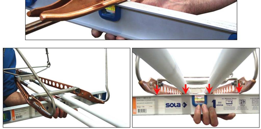
11 Installation Instruction Installation direction Installation direction Turn to adjust Place the JIG with red side to the installation direction. Adjust the spirit level for the red side. Turn the JIG 180 and place the JIG with yellow side to the installation direction. Adjust the spirit level for the yellow side. page 11
12 Negative Presag (Hogging) of the NS Install with negative presag: A + B + X 2 A X B page 12
13 Installation without Hogging page 13

14 Impacts on Runners page 14

15 Impacts on Runners page 15

16 Installation with Hogging page 16
17 Negative Presag (Hogging) of the NS Measure the high of the contact wire at the guide arm clamps before (A) and after (B) the installation location. A B page 17
18 Negative Presag (Hogging) of the NS Calculate the average value: A + B 2 A B page 18
19 Negative Presag (Hogging) of the NS Measure the hogging factor X X page 19
.")
20 Determination of Hogging Use a spring balance and pull the contact wire with 120 N N to measure hogging factor (x). page 20
21 Determination of Hogging N page 21
22 Negative Presag (Hogging) of the NS Install with negative presag: A + B + X 2 A X B page 22
23 page 23
24 General Layout item description pcs. 1 Phase break 1 2 messenger wire insulator 2 3 hanger 4 4 hanger 4 5 saddle clamp 2 6 forked collar socket 4 page 24
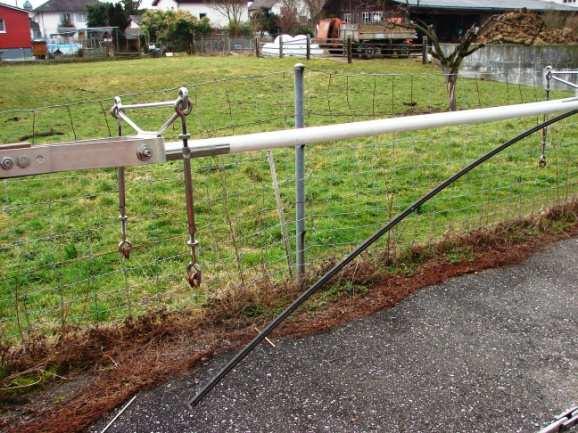
25 Installation Instruction Install the messenger wire insulator with saddle clamp and cable hangers page 25

26 Installation Instruction page 26
27 intermediate result READY page 27
28 Installation Instruction Mount Section Insulator onto contact wire without runners. Adjust position according to general layout drawing. page 28


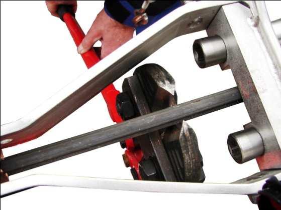
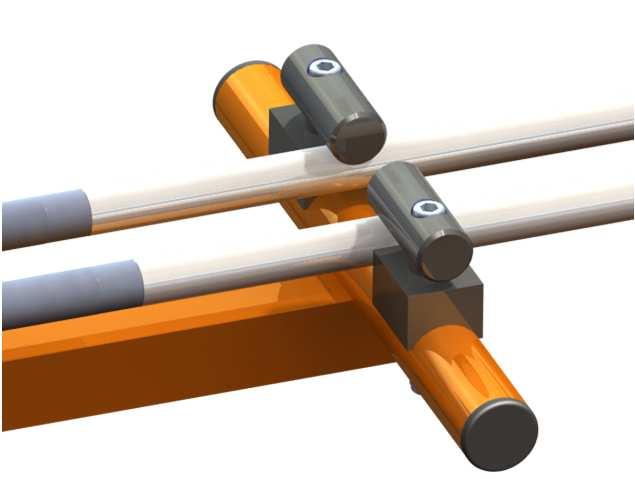
29 Installation Instruction WARNING! The teeth of the contact wire clamps must grip over the full length! page 29


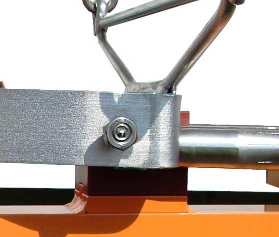
30 1. Installation Mount Section Insulator onto contact wire without runners. First tighten all bolts of the contact wire clamp with 50 Nm by using a tourque wrench and retighten 3 times 2. Mount counternuts and block with 50 Nm page 30

31 Installation Cut contact wire Bend contact wire ends up page 31
32 intermediate result READY page 32

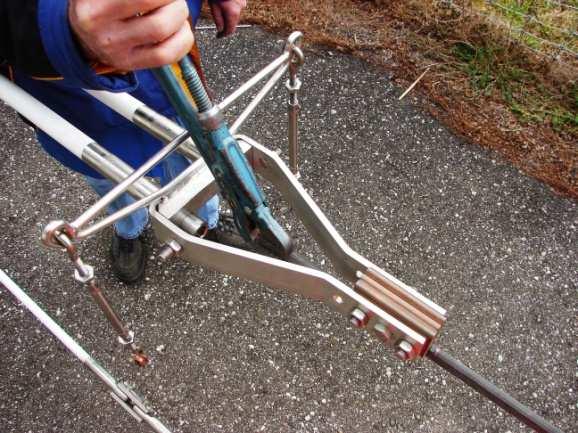
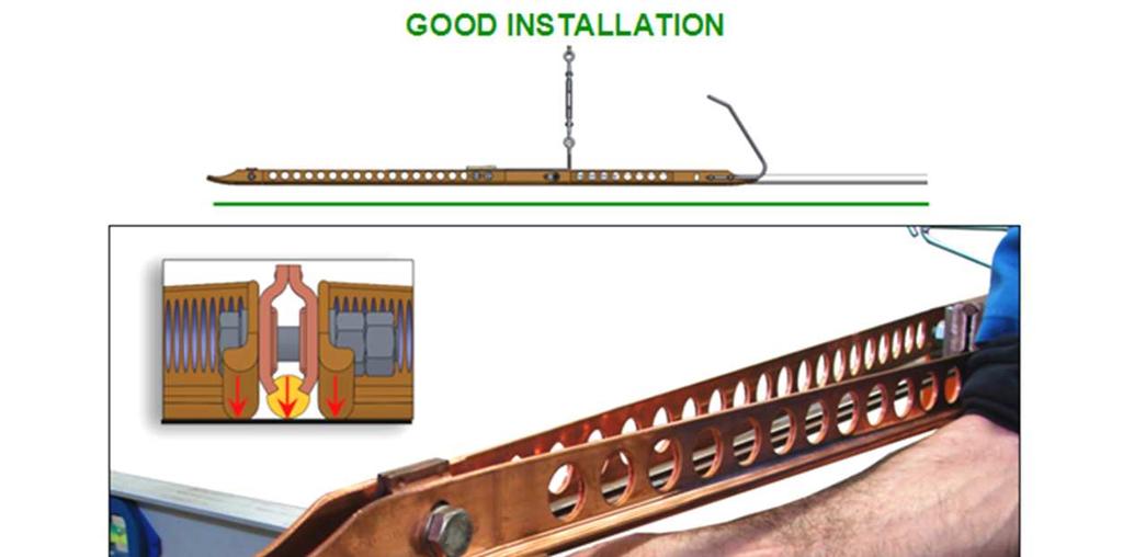
33 Installation Mount the Adjustment JIG fix center Turn 90 page 33
34 Installation Suspend the section insulator and adjust hogging Hogging (A+B/2)+X If not known x = 70 mm Adjust height of registration arm as well! page 34

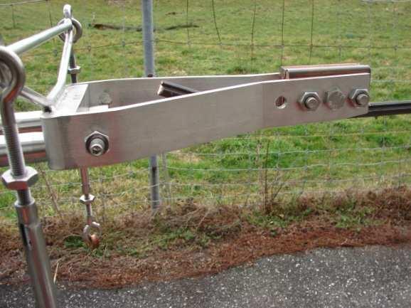
35 Installation Adjust precisely with turnbuckles in respect to the spirit level on the JIG page 35
36 Installation page 36


37 Installation Turn the JIG 180 and do the same adjustment with the JIG in yellow Turn 90 center fix page 37

+X If not known x")

38 Installation Suspend the section insulator and adjust hogging Hogging (A+B/2)+X If not known x = 70 mm Adjust height of registration arm as well! page 38
39 Installation Adjust precisely with turnbuckles in respect to the spirit level on the JIG page 39
40 Installation page 40


41 Installation Mount Runner on the left side Keep contact page 41


42 Installation Tighten the nuts with 50 Nm page 42
43 Installation Clip at Skid-Entrance Step 1: tighten the nut (green) with 50Nm Step 2: tighten the nut (purple) with 50Nm page 43


44 Installation Install and tighten the strengthening rods with 50 Nm Block with 20 Nm page 44
45 Installation page 45

46 Installation Mount Runner on the right side Keep contact page 46


47 Installation Tighten the nuts with 50 Nm page 47
 with 50Nm Step 2: tighten the nut (purple) with 50Nm")
48 Installation Clip at Skid-Entrance Step 1: tighten the nut (green) with 50Nm Step 2: tighten the nut (purple) with 50Nm page 48


49 Installation Install and tighten the strengthening rods with 50 Nm Block with 20 Nm page 49
50 Installation page 50
51 intermediate result READY page 51


52 Controll page 52
53 Earthing Phase 1 Phase 2 page 53
54 Installation and Design Recommendations Each neutral section insulator should be well centred and aligned parallel to the track. page 54
55 Most important points for NS Installation Skids in parallel to the track Hogging page 55
56 Last Point page 56
57 page 57
58 Maintenance Instruction page 58
59 Maintenance Instruction page 59

60 Maintenance Instruction page 60
61 Maintenance Instruction page 61

62 Maintenance Instruction page 62
63 The End Thank you for your attention page 63
INSTALLATION INSTRUCTION RRU DOUBLE LIGHT POLE MOUNT
 INSTALLATION INSTRUCTION RRU Double Light Pole Mount for installation of two RRU units on mast, towers or other vertical structures. CUE DEE YOUR INNOVATIVE PARTNER 1 CONTENTS 1. PRODUCT COVERED IN THIS
FABA. Installation Instructions. Conductor Bar System. Publication #FABA-03 3/1/04 Part Number: Copyright 2004 Electromotive Systems
 FABA Conductor Bar System Installation Instructions Publication #FABA-03 3/1/04 Part Number: 005-1062 Copyright 2004 Electromotive Systems 1S 100 Z Installation Instructions Contents: Basic Diagram - -
INSTALLATION RECOMMENDATIONS For The Con-Tech ODYSSEY Line Voltage Flexible Track System
 INSTALLATION RECOMMENDATIONS For The Con-Tech ODYSSEY Line Voltage Flexible Track System IMPORTANT SAFETY INSTRUCTIONS: Read all instructions before installation. Save these instructions for later use.
C 0.05" ALLEN WRENCH. Installation Instructions for Cirrus Channel Suspension T1 with 4" Square or Round Canopy. Section One: Adjusting Cable Position
 Doc # 90-CST-SQ_0 W. Fullerton Chicago, IL 0 Ph:.0.9 Fax:.9. www.pureedgelighting.com info@pureedgelighting.com 0 PureEdge Lighting. All Rights Reserved. Installation Instructions for Cirrus Channel Suspension
DO35 MAINTENANCE INSTRUCTIONS
 CUSTOMER INFORMATION SHEET NO. 038 DO35 MAINTENANCE INSTRUCTIONS (DO35 V3 LAUNCHED PRODUCTION JUNE 2017) Table of Contents 1.0 Replacing Spindle Bushes V3... 22 2.0 Replacing Locking Mechanism V3... 6
Session: Introduction to PPE and T&P
 Session: Introduction to PPE and T&P Learning Objectives Explain what safety PPE, tools and plants are, their purpose and their uses Evaluation Criteria Interactive Questioning Duration Resources Facilitator
MOTORIZED STANDARD SHADE WITH CABLES Installation Instructions
 Tools Needed Drill Measuring Tape Pencil 2 Level Plumb Line ¼ Masonry Drill Bit Hammer Linesmans Pliers Cable Cutters Phillips & Flat-Head Screw Driver 11/32 Socket or Open End Wrench 5/32 Allen Wrench
Introduction to PPE and T&P
 Introduction to PPE and T&P Learning Objective By the end of this session, you will be able to: Explain what safety PPE, tools and plants are, their purpose and their uses 2 Let s Discuss What do you mean
WARNING!! DO NOT LIFT DOORS UP WHEN THE HOOD IS OPEN. THE DOORS WILL HIT THE HOOD!
 WARNING!! DO NOT LIFT DOORS UP WHEN THE HOOD IS OPEN. THE DOORS WILL HIT THE HOOD! THIS KIT INCLUDES: 4 M8-1.25X30MM BOLTS WITH WASHERS 12 M8-1.25X40MM BOLTS WITH WASHERS 2 SHOULDER BOLTS WITH RIGHT AND
Clearview Railing System Installation Instructions
 Clearview Railing System Installation Instructions Disclaimer: AGS Stainless, Inc. has its Clearview Railing Systems designed by a professional engineer to meet the requirements of the latest national
Installation Instructions for Cirrus Suspension Downlight with Power - End Feed. Section One: 4" Flush Canopy Version
 Doc # 0-CSP-E_0 W. Fullerton Chicago, IL 606 Ph:.0. Fax:..6 www.pureedgelighting.com info@pureedgelighting.com 06 PureEdge Lighting. All Rights Reserved. Installation Instructions for Cirrus Suspension
Eraser Conveyor Belt Cleaning System IWARNING Always obey all applicable safety rules. Be sure all power to the conveyor has been disconnected and con
 INSTALLATION GUIDE LIB-CP-REA-03-01 Rev. 10 Eraser Conveyor Belt Cleaning System ARGONICS Eraser Conveyor Belt Cleaning System IWARNING Always obey all applicable safety rules. Be sure all power to the
Stanley Hand tools Stanley FatMax push-lock adjustable joint pliers. 3 piece Stanley FatMax pushlock. Stanley FatMax groove joint pliers.
 Stanley FatMax push-lock adjustable joint pliers Slip-resistant Bi-Material handle for a comfortable grip. Multipurpose jaws designed to grasp flat and round objects. Push-Lock technology allows for quick
TorqueMaster Replacement Spring
 TorqueMaster Replacement Spring Installation Instructions NOTE: Use these installation instructions in conjunction with the TorqueMaster Repair / Replacement Spring Program literature. Copyright 999 Wayne-Dalton
earth fault loop/pscc meter
 List of tools Claw hammer Club hammer Large hacksaw Small hacksaw Knife Wood saw large flat head screwdriver large posi-drive screwdriver terminal screwdriver flat file reamer long nose pliers Bolster
Installation Instructions
 Installation Instructions For 4 foot / 1.2m Diameter Ultra-high Performance Antenna Model ADxxG-4-T2 Before Installation, please read the instructions carefully. This instruction guide covers the installation
Ohbot. Eyes turn. servo. Eyelids open. servo. Head tilt. servo Eyes tilt. servo. Mouth open servo. Head turn servo
 Making Instructions Ohbot Ohbot has six servo motors. The servos allow each part of the face to be positioned precisely. Eyelids open servo Eyes tilt servo Eyes turn servo Head tilt servo Mouth open servo
TRACK TYPE DISCLAIMER. THESE INSTRUCTIONS ARE INTENDED FOR PROFESSIONAL GARAGE DOOR INSTALLERS and only apply to the fittings
 TRACK TYPE INSTALLTION INSTRUCTIONS DISCLAIMER THESE INSTRUCTIONS ARE INTENDED FOR PROFESSIONAL GARAGE DOOR INSTALLERS and only apply to the fittings Note: All references are taken from inside looking
Anti-Chattering Retrofit Assembly
 Anti-Chattering Retrofit Assembly Please follow through these instructions carefully and thoroughly. If you have questions, feel free to contact a Bend-Tech service representative at our office 651-257-8715
AUGMENT THE WEIGHT STACK SELECTION PRO SELECTION PRO MED INSTALLATION MANUAL
 AUGMENT THE WEIGHT STACK SELECTION PRO SELECTION PRO MED INSTALLATION MANUAL REV 1.0 LANG: ENG DATE: 2016.06.03 1/33 SOMMARIO 1 INFORMATION NOTE... 4 2 TOOLS... 4 3 PERSONAL PROTECTIVE EQUIPMENT... 4 4
MODEL H-9 HEAVY DUTY BENCH-TYPE UNDERCUTTER INSTRUCTIONS
 MODEL H-9 HEAVY DUTY BENCH-TYPE UNDERCUTTER INSTRUCTIONS CAPACITY: Between centers - 32" long x 12" diameter. Between roller V- supports - 35" long x 17" diameter. Maximum armature weight - 200 lbs. SAW
NOTE: The 1-piece panel is required for installation (the face mounts to the panel).
.") Installation Notes Flush Wood Plus Cypress Face Installation Before installing, make sure to install the one-piece panel, and disconnect the power cords making sure the Molex connector and two wires are
Installation Notes Flush Wood Plus Cypress Face Installation Before installing, make sure to install the one-piece panel, and disconnect the power cords making sure the Molex connector and two wires are
108 - CEILING HUNG RINGS
 Sales & Service sasportonline.com SA Sport (Canada) SA Sport (U.S.A.) 135 Forestview Road 4608 Fairlane Avenue P.O. Box 40 Fort Worth, Texas Orillia, Ontario USA 76119 Canada L3V 6H9 Telephone: (705) 325-2274
T-FITTINGS INSTALLATION INSTRUCTIONS
 T-FITTINGS INSTALLATION INSTRUCTIONS DISCLAIMER THESE INSTRUCTIONS ARE INTENDED FOR PROFESSIONAL GARAGE DOOR INSTALLERS and only apply to the fittings Note: All references are taken from inside looking
JSP60617 KIA EXPRESS SERVICE TOOL KIT
 JSP60617 KIA EXPRESS SERVICE TOOL KIT 60617-CAT TABLE OF CONTENTS JSP60617 Cart Inventory List...3 JSP60617 Cart Drawer Layout...4 Top Lid/Drawer Details...5 Drawer #1 Details...6 Drawer #2 Details...7
ClampStar Safe-T-Link Tether Installation Instructions for Deadends
 Tel.800-269-1462 Fax.800-311-9857 P.O. Box 100279, Birmingham, AL 35210 www.classicconnectors.com Classic Connectors, Inc. ClampStar Safe-T-Link Tether Installation Instructions for Deadends General Safety
ELECTRIC TOOL CORPORATION
 Cat. No. -0 / Hex Demolition Hammer Cat. No. 0-0 Spline Rotary Hammer MILWAUKEE ELECTRIC TOOL CORPORATION W. LISBON ROAD BROOKFIELD, WISCONSIN 00-0 -9-00 d 000 -9-00 d SpecialTools Require Forcing discs
Introduction To Automotive Technology
 Introduction To Automotive Technology UNIT 4: BASIc hand Tools LESSON 2: TYPES OF SCREWDRIVERS AND PLIERS I. Screwdrivers A. The standard screwdriver has a straight blade for turning screws with a slot
Rugged Ridge 2 Receiver Hitch Kit (J21068)
") Rugged Ridge 2 Receiver Hitch Kit (J21068) Installation Time: 1-2 Hours Tools Required: ¾ Open End Wrench 18 mm Socket ¼ drive Pliers/Needle nose pliers/channel locks, etc. Torque wrench Phillips head
Rugged Ridge 2 Receiver Hitch Kit (J21068) Installation Time: 1-2 Hours Tools Required: ¾ Open End Wrench 18 mm Socket ¼ drive Pliers/Needle nose pliers/channel locks, etc. Torque wrench Phillips head
ABM International, Inc. Navigator Assembly Manual
 ABM International, Inc. 1 1.0: Parts List Tablet (Qty. 1) Tablet mount (Qty. 1) NOTE: Mount may appear and operate different then image below Control Box (Qty. 1) Motor Power Supply (Qty. 1) 2 X-axis motor
Quick Set Dovetail Jig
 Quick Set Dovetail Jig FOR HELP OR ADVISE ON THIS PRODUCT PLEASE CALL OUR CUSTOMER SERVICE HELP LINE : 01509 500359 THE MANUFACTURER RESERVES THE RIGHT TO ALTER THE DESIGN OR SPECIFICATION TO THIS PRODUCT
MOR/ryde Steer Axle Suspension System
 MOR/ryde Steer Axle Suspension System (Double Eye Leaf Spring) Steer Axle Installation Instructions MOR/ryde International 1966 Moyer Avenue Elkhart, IN 46516 574-293-1581 www.morryde.com SRL153-001 REV.
Electrical Construction Name:
 Tools of the Trade The following are common tools that are used in the electrical industry. This hand-out is to help familiarize you with the tools, the terminology, and their use. Retractable Steel tape
1. Layout. Step 1. Step 2. Step 3. Fig. 1
 1-3/8 Panel Clamp Tools You Will Need: Tape Measure, Mason s String, Stakes, Hole Digger, Shovel, Level, Wheelbarrow, Wrenches or Adjustable Wrench, Hacksaw, Pliers, Cutting Pliers, Fence Stretcher and
STRAIGHT HANDLEBAR KIT
 STRAIGHT HANDLEBAR KIT P/N 2881973 APPLICATION All straight bar applications, excluding 550 Indy and Voyageur models BEFORE YOU BEGIN Read these instructions and check to be sure all parts and tools are
ASSEMBLY AND CARE INSTRUCTIONS CEILING HUNG RINGS 108
 ASSEMBLY AND CARE INSTRUCTIONS VERSION: 8920071 (Revised 06/15) CEILING HUNG RINGS 108 SALES AND SERVICE sasportonline.com SA Sport Canada and International 135 Forestview Road, PO Box 40 Orillia, Ontario,
Part 7 Assembling the X axis
 Part 7 Assembling the X axis 1 2 The X axis is a key part of the printer, it carries the extruder on a carriage that moves the extruder laterally in the X axis. The x axis itself is moved vertically on
Installing CNC Stepper Motor Mounts On A Sherline Mill
 Installing CNC Stepper Motor Mounts On A Sherline Mill P/N 6700 (6710 Metric) 5000/5100/5400/5410 Mills P/N 6705 (6715 Metric) 2000/2010 Mills USING THE TEMPLATE BLOCKS TO LOCATE NEW MOUNTING HOLES FOR
A500 ASSEMBLY & INSTALLATION INSTRUCTIONS
 ASSEMBLY & INSTALLATION INSTRUCTIONS 1 CONTENTS 2 Component Parts A B Canopy Mounting Plate C Cap (3) D Threaded Nipple E Threaded Standoffs (2) F Anchors (8) G #10 Screws (8) H Safety Cable (2) I Safety
C4 Fabrication Rock Slider Installation 14+ 5th Gen 4Runner w/o KDSS
 C4 Fabrication Rock Slider Installation 14+ 5th Gen 4Runner w/o KDSS Thank you for your purchase of the C4 Fabrication s 5th Gen 4Runner Rock Sliders! This product was carefully crafted to ensure a perfect
SERVICE ADVISORY SA-11
 SUBJECT: This document provides repair procedures of the Brush block assembly, and it: BRUSH ASSEMBLY REPLACEMENT BRUSH MODULE REPLACEMENT BRUSH REPLACEMENT CONTENTS: Page: I. GENERAL 1 II. NOMENCLATURE
ROOFSAFE ANCHOR & CABLE
 Installation Instructions ROOFSAFE ANCHOR & CABLE THE ULTIMATE IN FALL PROTECTION MANUAL Contents Guidelines for Installation 3 Top Bolt Installation 4 Toggle Installation 5 Concrete Installation 6 Component
These Installation Instructions are valid for antennas in the following version:
 Installation Instructions 4 ft CompactLine Antennas (with E-Mount 200 km/h) SB, SBX NMT 480-12(e) These installation instructions have been written for qualified, skilled personnel. The antenna shall be
HANDLEBAR KIT P/N APPLICATION BEFORE YOU BEGIN KIT CONTENTS TOOLS REQUIRED. Instr Rev Page 1 of 6
 HANDLEBAR KIT P/N 2881993 APPLICATION All straight bar applications, excluding 550 Indy and Voyageur models BEFORE YOU BEGIN Read these instructions and check to be sure all parts and tools are accounted
Fig. 2 DORMA-Glas Stand/Issue 02/03 Seite/Page 1/7
 FSW Installation instructions Track rail 75 x 72 mm 1. Ceiling substructure and installation of the track rail (Fig. 1): The track rail must be bolted over its entire length (including the stacking track
REC Series Rack Installation Guide
 REC Series Rack Installation Guide 1 REC Series Rack Installation Guide TABLE OF CONTENTS SECTION SAFETY WARNINGS 1 600 WIDE EXPLODED VIEW 2 800 WIDE EXPLODED VIEW 3 SWITCHING DOOR HANDING 4 STABILIZING
OX CNC. Mechanical Assembly Instructions. S.A. Brown & Maker Store
 OX CNC Mechanical Assembly Instructions S.A. Brown & Maker Store v1.2 07 2017 Contents About The Maker Store Ox CNC Kit... 2 Unpack and Check All Components... 2 Tools Required... 2 Pre-Assembly Notes...
Product #: Product #:
 STANLEY FATMAX Push-Lock Groove Joint Pliers Multi-purpose jaws designed to grasp flat and round objects. Push-Lock technology allows for quick and easy adjustment in 17 positions. Induction hardened jaws
Quick Hoops Seedling and Micro Green Bench Instruction Manual
 Quick Hoops Seedling and Micro Green Bench Instruction Manual 955 Benton Ave., Winslow, ME 04901 Phone: 1-877-564-6697 Fax: 1-800-738-6314 Email: service@johnnyseeds.com Web Site: Johnnyseeds.com This
Formula Suspension Fork RCC INSTALLATION AND ASSEMBLY INSTRUCTIONS
 Formula Suspension Fork RCC INSTALLATION AND ASSEMBLY INSTRUCTIONS COMPONENTS: 2 3 4 1 5 1) Remote regulator / Remote lever 2) Nut 3) Nut rubber cap 4) Complete cable 5) Cable rubber cap Note: In case
TO INSTALL SIDE PLATE:
 The Motion Pro PBR Chain Tool is designed to perform chain maintenance procedures quickly and easily by simply positioning the PBR Anvil Block and installing the rivet adapters as needed to Press, Break
Front axle components, overview
 j a t Front axle components, overview 40-1 General Information Load bearing components and parts of the suspension must not be welded or straightened. Vehicles without drive axle must not be moved, or
WARNING. BX Ford Explorer With Adaptive Cruise Control & Eco Boost Installation Instructions
 Please read BOTH these and the General Instructions before attempting to install or operate this equipment. 1. Blue Ox towing products and accessories are intended to be installed by Blue Ox Dealers who
INSTALLATION INSTRUCTIONS CHAIN-LINK FENCE AND GATE
 INSTALLATION INSTRUCTIONS CHAIN-LINK FENCE AND GATE 1 BEFORE YOU START, IT S IMPORTANT TO CHECK......That fence footings do not exceed legally established property lines. If uncertain, refer to real estate
REPAIR INSTRUCTIONS. Cat. No Cat. No MILWAUKEE ELECTRIC TOOL CORPORATION. SDS Max Demolition Hammer. SDS Max Rotary Hammer
 Cat. No. 9-0 SDS Max Demolition Hammer Cat. No. -0 SDS Max Rotary Hammer MILWAUKEE ELECTRIC TOOL CORPORATION W. LISBON ROAD BROOKFIELD, WISCONSIN 00-0 8-9-0 d 000 8-9-0 d Special Tools Require Forcing
Custom Pendant- Hardwire Assembly and Installation Instructions
 Custom Pendant- Hardwire Assembly and Installation Instructions CAUTION: BEFORE INSTALLING FIXTURE, MAKE SURE THE POWER TO THE CIRCUIT IS TURNED OFF AT THE MAIN FUSE BOX / CIRCUIT BREAKER UTILITY BOX.
SwingSafe Swing-Away Mailbox Support Diagram
 SwingSafe Swing-Away Mailbox Support Diagram Wood Mounting Plates Top Arm (B) Muffler Clamps (A) Carriage Bolts and Nuts Bottom Arm 4-Foot U-Channel Post USPS Recommended 42-44 Height Ground Slope Hex
WARNING Kia Spectra 5 Installation Instructions BX2713. Serial Number
 Please read BOTH these and the General Instructions before attempting to install or operate this equipment. 1. Blue Ox towing products and accessories are intended to be installed by Blue Ox Dealers who
THIS KIT INCLUDES: 8 M8-1.25X40MM BOLTS WITH WASHERS 8 M8-1.25X30MM BOLTS WITH WASHERS RIGHT AND LEFT HINGE
 Sal es@lambodoorscanada. com 2407A Kal adarave,ottawa,on K1V 8B9 THIS KIT INCLUDES: 8 M8-1.25X40MM BOLTS WITH WASHERS 8 M8-1.25X30MM BOLTS WITH WASHERS RIGHT AND LEFT HINGE 2 SHOCKS 565 PSI 2 SHOULDER
BUILD YOUR OWN. Pack 22
 BUILD YOUR OWN TM Pack 22 01 CONTENTS Assembly Guide 339 Stage 70: The front brake lever Stage 71: The oil hose and the twistgrip Stage 72: Fitting the front fork assembly Editorial and design by Continuo
Installation Instructions for OPGW Bolted Dead End
 INS-ACA015 OPGW Bolted Dead End Procedure 1. Disassemble dead end. Remove one bolt from the same side of each keeper. Loosen other bolts to permit conductor to be placed in the conductor groove. If keepers
Work Space Set-up. Slats will level the pipe during bending and help minimize twisting of the bow.
 Work Space Set-up Affix pipe bender to end of working surface Slats will level the pipe during bending and help minimize twisting of the bow. Make the slat height equal the distance from your work surface
Post-Paint>Fuselage>Interior>Controls>Fit rudder pedals
 Post-Paint>Fuselage>Interior>Controls>Fit rudder pedals Objectives of this task: To fit the rudder pedals and steering links to the aircraft, and fit the rudder cable to the rudder pedals and set the deflection
MANUAL SEALLESS STEEL STRAPPING TOOL MODEL A332
 OPERATION MANUAL / SPARE PARTS LIST MANUAL SEALLESS STEEL STRAPPING TOOL MODEL A332 13.2250.01 INDEX PAGE 1 SAFETY INSTRUCTIONS 2 2 WARRANTY CONDITIONS AND LIABILITY 3 3 APPROPRIATE USE 3 4 TECNICAL DATA
TABLE OF CONTENTS DRAWINGS
 TABLE OF CONTENTS Bifold Door Adjustment Procedures...pg 4 Bifold Door Maintenance...pg 6 Safety Concerns...pg 9 Troubleshooting...pg 10 Bifold Door Maintenance Checklist...pg 11 DRAWINGS EK 1880 Bifold
2009 Acura TL Installation Instructions
 Please read BOTH these and the General Instructions before attempting to install or operate this equipment. 1. Blue Ox towing products and accessories are intended to be installed by Blue Ox Dealers who
Installation Instructions for Vista Air Vertically Folding Walls
 Installation Instructions for Vista Air Vertically Folding Walls Use these instructions in conjunction with your shop drawings to see the specifics that are particular to the model you are installing.
STRENGTH Aligned teeth provide superior gripping power over standard vertical teeth. STRENGTH Diamond serrated jaws provide a firm grip
 STRENGTH Aligned teeth provide superior gripping power over standard vertical teeth STRENGTH Diamond serrated jaws provide a firm grip PLIERS AND SNIPS Locking Pliers Slip Joint Pliers Electrician s Pliers
ASSEMBLY AND ADJUSTMENT
 EDGE MONITOR ARM EDGE Rev A 2/17 Model EDGE-SLV Model EDGE-BLK Model EDGE-WHT ASSEMBLY AND ADJUSTMENT EDGE MONITOR ARM PARTS AND TOOLS PLEASE REVIEW these instructions before beginning the assembly and
Replacing the build plate clamps
 Repair manual Replacing the build plate clamps Instructions The build plate clamps hold the glass plate in place on the heated bed. There are two fixed in place at the back of the heated bed and two at
MANUAL SEALLESS STEEL STRAPPING TOOL MODEL A335
 OPERATION MANUAL / SPARE PARTS LIST MANUAL SEALLESS STEEL STRAPPING TOOL MODEL A335 13.2810.01 INDEX PAGE 1 SAFETY INSTRUCTIONS 2 2 WARRANTY CONDITIONS AND LIABILITY 3 3 APPROPRIATE USE 3 4 TECNICAL DATA
F5513 APOGEE 30"DIA 3LTS PENDANT INSTALLATION INSTRUCTIONS WARNING
 F5513 APOGEE 30"DIA 3LTS PENDANT INSTALLATION INSTRUCTIONS TROY LIGHTING DISCONNECT POWER BEFORE RE-LAMPING OR WIRING THE FIXTURE READ ALL INSTRUCTIONS COMPLETELY BEFORE STARTING INSTALLATION. CAUTION
Mainz Product Catalogue
 2018 Mainz Product Catalogue Stainless steel wire, fittings, hardware and tools for wire balustrades Stainless steel wire Stainless steel hardware and fittings Tools Mainz Pty Ltd Ph: (08) 92756246 www.wirebalustrades.com.au
Diva Acoustical Ceiling
 Installation Instructions Diva Acoustical Ceiling CONTENTS Important User Information...........................2 Safety Precautions.................................3 Required Tools....................................3
Hullavator Gas Spring Replacement (simplified)
") Hullavator Gas Spring Replacement (simplified) Some Thule Hullavators came with (original owner) lifetime warranties if you are the original owner of a defective Hullavator and can provide proof of purchase
Hullavator Gas Spring Replacement (simplified) Some Thule Hullavators came with (original owner) lifetime warranties if you are the original owner of a defective Hullavator and can provide proof of purchase
121PB - PRO UNEVEN BARS
 Sales & Service sasportonline.com Head Office 135 Forestview Road P.O. Box 40 Orillia, Ontario Canada L3V 6H9 Toll Free (800) 563-6479 Phone (705) 325-2274 Fax (705) 325-1485 USA Office 7879 Will Rogers
USSC LLC 4 ONE LLC FIELD MODIFICATION INSTRUCTIONS
 1 OF 17 A 1. PURPOSE: Instructions for in field replacement of 9004 mechanical suspension top pan 2. SCOPE: 9004 mechanical suspension with legacy two point LX back frame and current LX back frame 3. PROCEDURE:
Chapter 6. General-Purpose Tools and Equipment, Service Information
 This sample chapter is for review purposes only. opyright The Goodheart-Willcox o., Inc. ll rights reserved. ate lass hapter 6 General-Purpose Tools and Equipment, Service Information Learning Objectives
Tools for Plumbing. Introduction
 2 Tools for Plumbing Introduction So far, we have studied the importance of plumbing system, its stages and the role and responsibilities of a plumber. We will now look at the various tools that help a
CMA-455 Suspended Ceiling-Tile Reinforcing Kit
 INSTALLATION INSTRUCTIONS CMA-455 Suspended Ceiling-Tile Reinforcing Kit The provides a sturdy support for LCD/DLP hanging brackets (and certain other products) when installing these products in a suspended
Retractable Tongue Kit Model MPG457 Instructions
 Malone MicroSport Trailer Retractable Tongue Kit Model MPG457 Instructions TM Take a few moments and read through these instructions to familiarize yourself with the step by step assembly process before
ATLANTIS RAIL HandiSwage Installation Instructions ATLANTIS RAIL Contact Information Atlantis Rail Systems November, 2013
 ATLANTIS RAIL HandiSwage Installation Instructions ATLANTIS RAIL Contact Information Atlantis Rail Systems November, 2013 Atlantis Rail s HandiSwage System is an easy to use cable railing product utilizing
Installation instructions, accessories. TV receiver, digital
 Installation instructions, accessories Instruction No 30756561 Version 1.1 5 Part. No. 30756181, 30756569 TV receiver, digital Volvo Car Corporation TV receiver, digital- 30756561 - V1.1 Page 1 / 36 Equipment
TWL 1500 TORQUE WRENCH LOADER
 TWL 1500 TORQUE WRENCH LOADER OPERATOR S HANDBOOK (PART NUMBER 60246.1) CONTENTS PAGE 1 OF 8 INTRODUCTION 2 SPECIFICATION 3 ITEMS SUPPLIED 3 AVAILABLE OPTIONS 3 ASSEMBLY INSTRUCTIONS A. ASSEMBLY OF TRANSDUCER
YALE FIGURE 500 & 500R CLOSURE OPERATION AND MAINTENANCE INSTRUCTIONS
 YALE FIGURE 500 & 500R CLOSURE OPERATION AND MAINTENANCE INSTRUCTIONS IMPORTANT INFORMATION Note To Supervisor: Please share this information with your employees and make sure they have received training
Maintenance Information
 16575177 Edition 1 June 2006 Electric Angle Wrench QE8 Series Maintenance Information Save These Instructions General Instructions: Refer to Suggested Tools Parts List for quick reference to the tools
INSTALLATION INSTRUCTIONS FOR HAND OPERATED MODELS: 170, 171-R, 171-N, 172, 260
 INSTALLATION INSTRUCTIONS FOR HAND OPERATED MODELS: 170, 171-R, 171-N, 172, 260 I. SUSPENDED INSTALLATIONS NOTE: MODEL 260 FENSTEEL TRACK IS ASSEMBLED IN THE SAME MANNER AS DESCRIBED BELOW WITH THE EXCEPTION
ROBOT KR 350. Installation, Connection, Exchange. Ro/Me/03/ en. 1of 26
 ROBOT KR 350 Installation, Connection, Exchange 1of 26 e Copyright KUKA Roboter GmbH This documentation or excerpts therefrom may not be reproduced or disclosed to third parties without the express permission
MICC Ltd Unit 21 Sedling Road Wear East Industrial Estate Washington Tyne & Wear NE38 9BZ Tel: +44 (0)
") MICC Ltd Unit 21 Sedling Road Wear East Industrial Estate Washington Tyne & Wear NE38 9BZ Tel: +44 (0)191 416 8884 MINERAL INSULATED CABLE PRECISION DRILLING MACHINE INSTRUCTION MANUAL (Amended for new
MICC Ltd Unit 21 Sedling Road Wear East Industrial Estate Washington Tyne & Wear NE38 9BZ Tel: +44 (0)191 416 8884 MINERAL INSULATED CABLE PRECISION DRILLING MACHINE INSTRUCTION MANUAL (Amended for new
Printrbot Simple (Model 1403) Rev F Printrboard
 Rev F Printrboard") Printrbot Simple (Model 1403) Rev F Printrboard Printrbot Simple is currently shipping with the Rev F Printrboard. Check which rev Printrboard your Simple kit includes and use the corresponding instructions.
Printrbot Simple (Model 1403) Rev F Printrboard Printrbot Simple is currently shipping with the Rev F Printrboard. Check which rev Printrboard your Simple kit includes and use the corresponding instructions.
Connecting the Channel A
 20 Edge Lighting. All Rights Reserved. Installation Instructions for Cirrus Channel Suspension T, Tubular Lens w/2sq or 2RD Canopy IMPORTANT INFORMATION - This product is suitable for indoor locations.
Installation Guide. Overview
 Installation Guide Thank you for selecting a DuctSox SkeleCore Pull-Tight with Cable System. This guide will be helpful for installing the system. The key to a successful SkeleCore Pull-Tight installation
INSTRUCTIONS FOR HIT LOCK MORTISER
 1825 VIA BURTON ANAHEIM CA 92806 714-772-5202 / FAX 714-772-2302 EMAIL: MAIL@MAJORMFG.COM WEB: WWW.MAJORMFG.COM INSTRUCTIONS FOR HIT-66-200 LOCK MORTISER WHEN USING POWER TOOLS ALWAYS WEAR EYE AND EAR
Tools Needed Hardware Provided (per shade) Hardware Needed
 Hardware Needed") Baby Grande or Grande Motorized (XQ5 Premium) Shade with Cables and Housing Installation Instructions Tools Needed Hardware Provided (per shade) Hardware Needed Drill 3/8 Metal Drill Bit Measuring Tape
Baby Grande or Grande Motorized (XQ5 Premium) Shade with Cables and Housing Installation Instructions Tools Needed Hardware Provided (per shade) Hardware Needed Drill 3/8 Metal Drill Bit Measuring Tape
Independent Containment System (ICS)
") Installing the Independent Containment System (ICS) Complete these instructions to install the Independent Containment System (ICS). Prerequisites This installation requires a team of at least two people.
Installing the Independent Containment System (ICS) Complete these instructions to install the Independent Containment System (ICS). Prerequisites This installation requires a team of at least two people.
MTS-SP100. RENOGY Pole Mount System E Philadelphia St, Ontario, CA Version: 1.2
 MTS-SP100 RENOGY Pole Mount System 2775 E Philadelphia St, Ontario, CA 91761 1-800-330-8678 1 Version: 1.2 Important Safety Instructions Please save these instructions. This manual contains important safety,
Professional Pliers. Quality to Depend on
 Professional Pliers Quality to Depend on - 227 - High Leverage Pliers High Leverage Pliers High Leverage pliers boast a labor-saving design to generate greater productivity with less effort. Ergonomic
INSTALLATION: D1-NOTCH DRYWALL TRIM FLANGE
 T F W 604.549.979 604.549.9555 fluxwerx.com INSTALLATION: D1-NOTCH DRYWALL TRIM FLANGE fixture housing endcap kit optic kit join kit notch 2 cross section notch 4 cross section 4 4" 4-11/2" 4 /8 (111)
NATIONAL CERTIFICATE (VOCATIONAL) ENGINEERING TECHNOLOGY NQF LEVEL 2 NOVEMBER 2010
 ENGINEERING TECHNOLOGY NQF LEVEL 2 NOVEMBER 2010") NATIONAL CERTIFICATE (VOCATIONAL) ENGINEERING TECHNOLOGY NQF LEVEL 2 NOVEMBER 2010 (6021012) 24 November (X-Paper) 09:00 12:00 This question paper consists of 10 pages and 1 annexure. (6021012) -2- NC920(E)(N24)V
NATIONAL CERTIFICATE (VOCATIONAL) ENGINEERING TECHNOLOGY NQF LEVEL 2 NOVEMBER 2010 (6021012) 24 November (X-Paper) 09:00 12:00 This question paper consists of 10 pages and 1 annexure. (6021012) -2- NC920(E)(N24)V
INSTALL INSTRUCTIONS: FRAME REPAIR KIT
 INSTALL OF FRAME REPAIR KIT (523-203) Ford Ranger 2004 1993 General Tech Tips: Disconnect and Remove Battery Remove fuel tank and clamp, or disconnect fuel lines. Double check for leaking fuel. Ensure