Technical Documentation Lift Advanced
|
|
|
- Peregrine Dawson
- 5 years ago
- Views:
Transcription
1 Technical Documentation Lift Advanced 1
2 1 Introduction Basic Information Hinge Recommendations... 5 Lift Advanced HF... 5 Lift Advanced HK Usage of Aluminium Fronts mm Aluminium Framed Fronts mm / 55mm wide Aluminium Framed Fronts Gas Pressure Springs... 7 Description of the Component... 7 Technical & Logistical Information... 7 Assignment Article Numbers & Spring Force... 9 Selection of the Correct Spring... 9 Mounting of the Gas Pressure Spring... 9 Disfitting of the Gas Pressure Spring Fitting Preparation of Fitting Contents Fittings Set Preparation of the Cabinet Preparation of the Flap(s) Preparation of Cross Member (only for Lift Advanced HL & HS) Fitting Lift Advanced HF Usage of Spacers Fitting Lift Advanced HK Fitting Lift Advanced HL & HS Adjustment Adjustment of Gaps Adjustment of the Closing Damper Adjustment of the spring force Adjustment of the Opening Angle Stop Description of Defects and their Correction All Variants Distortion of the fitting base plate Lift Advanced HF Top flap closes properly, bottom flap tilts frontward Fitting arms are bent outwards, arms eventually grinding in the cabinet.. 36 Flap does not close correctly Flaps close very loudly Lift Advanced HK Flap is tilted in front of the cabinet / Flap does not close properly Fitting arms bend outwards Lift Advanced HS / HL Fitting arms grind against the cabinet / HFT / CM / DW 2
3 Flaps stays tilted in front of the cabinet / Flap does not close correctly Fitting arm collides with the cabinet top panel when open (only HS) Others Location of the contact points of the gas pressure springs Identification of the Fittings when fitted
4 1 Introduction The handbook is divided into several parts and should aim to represent all the aspects of the Lift Advanced series in a clear, comprehensive and descriptive manner. Covering everything from mounting to fine adjustment and a catalogue of defects, this document should serve as an aid to answer any questions quickly and substantially. Information which is already given in the catalogue documents (e.g. hole pattern, calculation of hole positions, etc.) are not again listed here. Symbols used Tips & Tricks Attention! Important note! Related information 4
 or 110 (e.g. Intermat 9943) can be used. The maximum opening angle of the flap is limited to approx.")
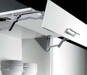
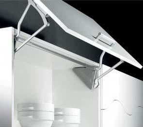
5 2 Basic Information 2.1 Hinge Recommendations Lift Advanced HF For this fitting, hinges with an opening angle of 110 should be used (e.g. Intermat 9943). The application of Sensys is possible. Lift Advanced HK For this fitting, hinges with an opening angle of 95 (e.g. Intermat 9936) or 110 (e.g. Intermat 9943) can be used. The maximum opening angle of the flap is limited to approx. 85 through the flap fitting. The application of Sensys is possible for applications as listed below and enables a gentle closure of the flap, especially large flaps. Internal cabinet height Weight Sensys? From 12.4kg OK All weights OK 2.2 Usage of Aluminium Fronts 19mm Aluminium Framed Fronts Holes for the adapter at least 42 mm away from the frame top edge otherwise they will collide with the connecting angle of the aluminium frame. The result of this is that specific configurations cannot be realised in case of a HFflap with unequally sized flaps. 5

6 Depending on the overlay, it can happen that there is a gap between the frame and the adapter. The below given table shows the assignment of the possible lateral overlays in gap dimensions ranging from 0mm to 5mm for the different fittings version. Gap min = 0mm max = 5mm HF HL HS Front adapter for Lift Advanced HF, Lift Advanced HL, Lift Advanced HS For Lift Advanced HK, due to the length of the adapter, the gap dimension of 0mm cannot be achieved. Gap HK min = 2.8mm max = 5mm Overlay Front adapter for Lift Advanced HK 45mm / 55mm wide Aluminium Framed Fronts Preparation of this aluminium profile for Lift Advanced by HFT is currently NOT possible. For connecting the fitting to a 45mm or 55mm wide frame so-called blind rivet nuts M6 must be flush mounted in the respective drilling positions in the frame. ATTENTION: Drilling positions should not be in the area of the aluminium frame connecting angle! 6

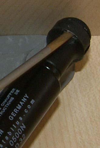
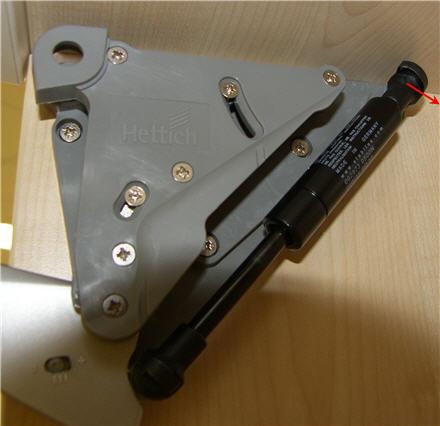
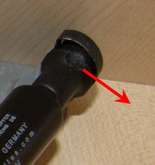
7 2.3 Gas Pressure Springs Description of the Component Technical & Logistical Information Gas pressure springs are filled with gas (nitrogen) and oil. The oil has several uses. It helps to lubricate the piston rod. It also collects on top of the seal, forms an additional barrier between the interior of the spring and the surrounding and like this helps keeping gas pressure loss low. However, this can only work, if the piston rod faces downwards (see image above). Therefore, storage and installation of the spring must be done with the piston rod facing downwards. ATTENTION: Storage ALWAYS with piston rod facing downwards, NEVER with piston rod facing upwards (otherwise loss of pressure may occur!) ATTENTION: Mounting ALWAYS with piston rod facing downwards (otherwise loss of pressure may occur!) (See photo page 8) Storage time should be kept as short as possible because the durability could be affected by long or improper storage. 7

8 Correct! Wrong! Other technical information: Operating temperature between 30 C and +80 C Oil for lubrication of the piston rod, sealing of the sealing gap and dampening of opening action Due to technical reasons there can be tolerances of the spring force of up to 15%, these possible fluctuations will be considered in the dimensioning of the spring strength The gas pressure spring cannot be completly sealed to the outside, approximately 2-3% of the gas escapes from the spring every year ( Permeation ) Gas pressure spring does not hold the flap closed; the spring always aims to open the flap If the selection table specifies two spring strengths, the stronger spring has to be chosen See also references to complaints that have arisen. 6582YG = Part number 0450N = Details of spring force 317/09 = Production day / Production year 8
9 Assignment Article Numbers & Spring Force Catalogue Spring force Catalogue Spring force number number N N N N N N N N N N N N N N N Selection of the Correct Spring The required spring force depends on the chosen fitting variant, the inner cabinet height and the weight of the flap. In the catalogue documentation, tables which allow the selection of the correct spring can be found. If the selection table specifies two springs, then the stronger spring has to be chosen. ATTENTION: For selection of the correct spring strength, the exact weight of the front including the handle must be considered. Mounting of the Gas Pressure Spring The gas pressure springs are clipped on to the fitting with ball cups fitted on ball pins. The ball cup is locked in position on the ball pin by means of steel spring. The gas pressure spring must be fitted with the piston rod facing downwards; otherwise an increased loss of pressure and premature malfunction of the spring is possible (see photo S.10) 9
10 Correct! Wrong! Disfitting of the Gas Pressure Spring To disassemble the spring, the steel spring is loosened at the top ball pin using a fine screwdriver and the ball cup is removed from the pin. ATTENTION: Hold the flap in place, risk of injury! The spring is turned downwards and the steel spring of the lower ball cup is loosened and the spring is removed. (See photos page 11) ATTENTION: To use the spring, if needed, in another fitting, the spring steel should not be slipped fully from the ball cup. 10
11 11

12 3 Fitting 3.1 Preparation of Fitting Contents Fittings Set 4x brass expanding dowel with hex head for holes Ø10x12mm, to drive into the flap 4x M6-threaded screw with hex socket in the head, to connect the fitting arm to the flap 6x Euro screws with Pozidriv for holes Ø5x12, to screw the fitting into the cabinet 2x allen keys in the required sizes Preparation of the Cabinet Drill the holes (Ø5x12) for securing the fitting into the cabinet. TIP: Use the drilling template included in the box If required, drill holes for the mounting plates in the cabinet and fix the mounting plates (Lift Advanced HF & HK) ATTENTION: Position the hinge min. 90 mm from the inner edge of the cabinet side! Preparation of the Flap(s) Calculate hole positions (see catalogue documentation) Drill the holes (Ø10x12) TIP: The more accurate the holes are drilled, the lesser adjustments are required later. In case of inaccurate holes, the flaps can maybe not be brought to the correct position by using the adjustment possibility given in the fitting. If required, drill holes for the hinge and mount the hinge (Lift Advanced HF top flap & HK) 12


 For Lift")
 For cabinet widths of 600mm, 1200mm and 1800mm, cross members are")
13 ATTENTION: Position the hinge min. 90 mm from the inner edge of the cabinet side! Flush insertion of the brass expanding dowels ATTENTION: Dowels must be absolutely flush inserted. Better a little too deep than projecting outside! Screw in the M6-screws into the dowel far enough that the dowels expand (Expanding the dowel will prevent the dowel from rotating during the subsequent fitting) Screw out the M6-screws again until only a few turns of the screw thread remain in the dowel (for the top flap HF and flap HK remove the screws) For Lift Advanced HF, if required, fit spacer for centre joint (see page 21 Usage of Spacers ) Preparation of Cross Member (only for Lift Advanced HL & HS) For cabinet widths of 600mm, 1200mm and 1800mm, cross members are available (the cross member automatically adjusts to different side panel thicknesses from 16-19mm) 13

14 For other cabinet widths, the mid section of the cross member must be cut to length (cabinet width 290mm) 14
15 3.2 Fitting Lift Advanced HF All the fitting steps shown are to be executed in the sequence presented below. Ignoring any fitting step can lead to severe damages and defect of the fitting or the fitting not being properly adjustable. ATTENTION: The fitting steps, especially 4, 6 and 8 are to be followed NECESSARILY. 1 Fix the fitting into the cabinet 2 Check whether spacer must be used Hole position J of the bottom flap smaller than 65mm Fit the spacer on the flap (see also page 21 Usage of Spacers ) 3 Mount the top flap to the cabinet with the hinges 15


16 Adjust the joints of the top flap at the hinges ATTENTION: It is absolutely necessary that the joint of the top flap is adjusted at this point during the fitting! 4 TIP: Use stop attachments as this will simplify the adjustment of the joint. Check the fit of the flap by pressing the corner of the flap from the front; in case of air between the flap and the cabinet, readjust the hinge. 5 Hold up the flap and clip on the gas pressure springs ATTENTION: Piston rod pointing downwards! 6 Screw the fitting arm to the top flap (M6-screws in expanding dowel) ATTENTION: It must be ensured that the top flap can be opened fully (min. 110 ) and does not get jammed in by the top panel (in this case: change the depth adjustment of the hinge) 16
 Tighten the screw on both sides in the joint!")


17 7 8 9 Close the flap ATTENTION: When closing, there could be crack sound, because the joint screws have not been tightened (see next step in fitting) Tighten the screw on both sides in the joint! ATTENTION: This fitting step is extremely important. If the screw is not fixed or not tightened sufficiently, it will result in increased wear and tear of the joint and the premature breakdown of the fitting! (see also defect pictures, page 33) Open the flap. ATTENTION: Risk of injury due to very forceful opening because the bottom flap is not yet installed! 10 Hang the bottom flap in the fitting with the premounted screws. 17


18 11 Tighten the screws Adjust the joint of the bottom flap 12 Height adjustment +/- 2mm 1. Loosen the mounting screws 2. Lower the flap: turn out the set screw 2. Raise the flap: Screw-in the set screw 18
, the bottom flap must be set as high as possible so")


19 3. Tighten the screws 13 ATTENTION: While using spacers (see page 21), the bottom flap must be set as high as possible so that no air remains between the spacers. Lateral adjustment Screw-in the set screw: Fitting is pushed to the outside. Move the flap to the right: Screwin the set screw at the left fitting arm, screw out the set screw at the right fitting arm Move the flap to the left: Screw in the set screw at the right fitting arm, screw out the set screw at the left fitting arm 19
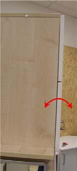
20 14 Tilt adjustment 20

 and 770 925mm (Article 9079615) and must be installed if the position")

21 Usage of Spacers To prevent the flap connection from overstretching during opening (by pulling the handle, the bottom flap is pushed backwards in the central joint), spacers must be placed in the central joint. This is required if the bottom flap can not support itself against the fitting arm, which might be the case with very high cabinets or unequally divided flaps. The spacers are included with the fitting Lift Advanced HF for the cabinet heights mm (Article ) and mm (Article ) and must be installed if the position of the upper hole on the bottom flap (value J see catalogue) is less than 65 mm from the upper edge of the flap. The spacers can only work effectively if no air is left between the angles. Therefore bottom flap has to be adjusted upwards until the spacers are pressed against each other. The overstretching of the bottom flap connection leads to wear and tear of the tilt adjustment and after some time the bottom flap no longer stays straight in front of the cabinet, but tilts forward at the top edge ( see also defect picture, page 33). 21


22 Bottom flap is supported by the fitting arm, spacer not required. Bottom flap cannot support itself on the fitting arm, spacer required. With the help of the spacer, the central reveal can be defined and the bottom flap cannot be overstretched. 22

23 3.3 Fitting Lift Advanced HK All the fitting steps shown are to be executed in the sequence presented below. 1 Fix the fitting into the cabinet 2 Mount the top flap to the cabinet with the hinges 3 Adjust the joints of the flap at the hinges 23
 ATTENTION: While tightening the screws, fix them in the middle position of the elongated holes of the fitting arm If the flap does")
24 4 Hold up the flap and clip-on the gas pressure spring ATTENTION: piston rod points downward! 5 6 Fix the fitting arm to the flap (M6-screws in expanding dowel) ATTENTION: While tightening the screws, fix them in the middle position of the elongated holes of the fitting arm If the flap does not close correctly, there could be two reasons 1. Closing damper too strong reduce closing damper (see page 30) 2. Tension in the fitting (depending on the hinge fitting) Loosen the screws of the front adapter and change the position of the screws in the elongated holes by pushing the adapter, fix the screws again. 24

25 3.4 Fitting Lift Advanced HL & HS All the fitting steps shown are to be executed in the sequence presented below. 1 Fix the fitting into the cabinet 2 Clip-on the gas pressure spring ATTENTION: Piston rod points downward! 3 Hang the flap in the fitting with the pre-assembled M6-screws and tighten the screws. ATTENTION: While tightening, hold the parts of the front adapter in alignment. Otherwise it can lead to the twisting of the parts of the front adapter. (see also defect picture, page 33) 25


26 Mount the cross member. Push the middle part of the cross member several times strongly towards the left and the right in the adapters to push the adapters tightly onto the pins of the fitting. Centre the middle part and fix the set screws of the adapter TIP: Due to aesthetic reasons, the set screws should point backwards. 4 ATTENTION: If the cross member has been fitted earlier than the flap or if the flap has been disassembled again for some reason, the fitting should not be pulled down at just one side ATTENTION: Because of the shape of the fitting arm for Lift Advanced HS, it can happen that the fitting arm touches the front edge of the top panel. In this case opening needs to be reduced(see page 31) Adjust the joint of the bottom flap 26


27 5 Height adjustment 1. Loosen the screws 2. Height adjustment in the maximum position 2. Height adjustment in the minimum position 3. Tighten the screws 27


28 6 Lateral adjustment 1. Loosen the screws on both front adapters 2. Bring the flap in the desired position by hand. 3. Tighten the screws on both front adapters 28


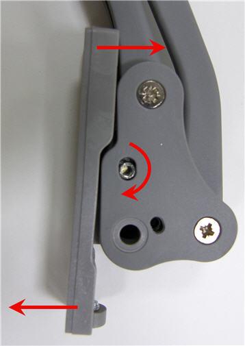
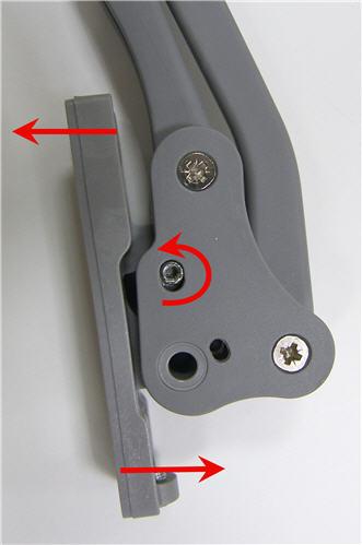
29 7 Tilt adjustment 1. Loosen the screws 2. maximum tilt adjustment 2. minimum tilt adjustment 3. Tighten the screws ATTENTION: Adjustment will be visible only after the screws are tightened 29


30 4 Adjustment 4.1 Adjustment of Gaps The adjustment of gaps is shown in section 3 for each case of the fitting of fittings. 4.2 Adjustment of the Closing Damper After the fitting is completed as per section 3, the closing action of the flap should be checked and optimised if required. The fitting comes with the damper adjusted to maximal strength. If the flap does not close or closes very slowly, then the damping action should be reduced. For this, loosen the screws indicated (do not take out) and push the damper down as required and then tighten the screw again. Maximum dampening action Minimum dampening action 30


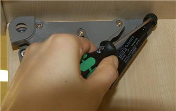
31 4.3 Adjustment of the spring force Fine alignment depending on the flap weight and personal instinct of the user Adjustment +/- 10% of the spring force By increasing the spring force, the opening angle is decreased minimally ATTENTION: The spring force should be adjusted equally on both the sides. Spring force max Spring force min 4.4 Adjustment of the Opening Angle Stop With the help of the opening angle stop, the upper end position of the flap can be regulated downwards, so that it is possible, e.g. for shorter persons to comfortably operate the flap. The adjustment is set to maximum opening of the flap from the factory. In order to reduce the opening, the below given screw must be loosened. Then pull the fitting arm a little downwards to the required opening and push down the opening angle stop with the help of a screwdriver till the opening angle stop rests on the fitting arm. Tighten the screw firmly in the required position. 31


32 ATTENTION: The screw must be firmly tightened; otherwise the opening angle stop moves again into the original position due to the pressure of the fitting arm. Maximum opening angle Minimum opening angle ATTENTION: Due to the shape of the fitting arm for Lift Advanced HS, it can happen that the arm touches the front edge of the cabinet top panel. In this case, the opening has to be reduced. TIP: It is advisable to reduce the opening for Lift Advanced HK. The beginning of the closing action is more comfortable as less force must be applied. Background: In comparison to other opening types, the comparatively stronger spring is used for the same flap size and weight for HK because the lever which is formed by the flap is the biggest; the spring force must be overcome by the user while closing and it is the highest at the start of the closing action. 32

33 5 Description of Defects and their Correction 5.1 All Variants Distortion of the fitting base plate Details Cause Correction Prevention 1. Distortion of fitting base plate Happens possibly due to usage of very strong gas pressure springs. Does not affect the function of the fitting and is not visible after the installation of the cover cap, hence is not a defect or a reason for complaint

 This is a result of overstretching of bottom front fitting during the usage on very huge cabinet heights.")
34 5.2 Lift Advanced HF Top flap closes properly, bottom flap tilts frontward Details Cause Rectification Prevention 1. while installation Overlay adjustment on the hinge has been done after the tightening of the joint screw 2. after some time of use Tilt adjustment screw on the front fitting is worn-out and can no longer hold the flap straight. (see photo) This is a result of overstretching of bottom front fitting during the usage on very huge cabinet heights. (see also page 15) Remove the bottom flap, loosen the joint screw, do the adjustment at the hinge as required. Tighten the joint screw. Fit the bottom flap again. (see also page 12) If the defect has happened recently and the wearing out of the screw has not progressed too far, then the transparent spacers can be introduced in the central joint. This will prevent a further overstretching of the front fitting. While fitting, after the fastening of the joint screws, do not carry out any adjustments at the hinge. Fitting of the spacer in situations as described in page 21 (J<65mm) 34
35 3. for aluminium frames Aluminium frame is not fixed with flush mounted screws. If the screws lie in the range of the fitting arms, the screw head prevents the flat attachment of the flap on the fitting arm. If no permanent solution can be attained by the usage of spacers, the fitting has to be exchanged. ATTENTION: while installing a new fitting, spacer has to be fitted Connecting screws of the frame have to be fitted flush. Connecting screws of the frame have to be fitted flush. 35


36 Fitting arms are bent outwards, arms eventually grinding in the cabinet Details Cause Rectification Prevention During fitting, the joint screw has not been used or not been fixed firmly. Hence the upper metal arm moves against the lower plastic arm and this leads to abrasion and wearing out. After some time there is so much play in the joint that the metal arm tilts and the plastic arm pushes outward. In case of continued wear, the fitting arm grinds against the cabinet The wear and tear cannot be undone. The fitting must be replaced. ATTENTION: Fitting instruction has to followed correctly! Pay attention to the fitting sequence and carry out all the fitting steps carefully. 36
 Closing damper too strong Top flap wrongly mounted, fitting sequence not followed. 2.")
37 Flap does not close correctly Details Cause Rectification Prevention 1. while assembling Dowel on the flap not inserted flush (see photo) Closing damper too strong Top flap wrongly mounted, fitting sequence not followed. 2. after some time of use Wear and tear in the joint (see page 38 Fitting arms are bent outwards ) Disassemble the fitting, flush fit the dowel and re-fit Reduce closing damper action (see page 30) Disassemble both the flaps, loosen the joint screws and carry out the installation as per specification. see page 40 Fitting arms are bent outwards Dowels must be fitted flush in the flap. - Follow the fitting sequence! see page 40 Fitting arms are bent outwards 37
38 Flaps close very loudly Details Cause Rectification Prevention In the fitting arm, there is a spring steel which pulls the flap close (like a cup hinge). The spring steel pulls the flap very strongly over the last centimetres, this might make a noise at the time of closing. This is NOT a defect, but a feature of the fitting. Use Sensys hinges or Intermat hinges with additional damper. - 38
39 5.3 Lift Advanced HK Flap is tilted in front of the cabinet / Flap does not close properly Details Cause Rectification Prevention 1. while fitting, the flap sticks out on the top Depth adjustment of the hinge Adjust the depth adjustment of the hinge - 2. while fitting, the flap sticks out at the bottom Dowel on the flap not inserted flush (see photo) Disassemble the fitting, flush fit the dowel and re-fit Dowels must be fitted flush in the flap. Tension in the fitting Open the flap, loosen the front mounting screws on the flap and push the front mounting in the elongated holes. (see photo) While assembling, place the front mounting screws in the centre of the elongated holes. This setting should be suitable for when drilling of the hinges / mounting plates and the fitting have been carried out exactly. Closing damper too strong Reduce closing damper action (see page 30) - 39

40 Fitting arms bend outwards Details Cause Rectification Prevention 40
 (Can happen while fastening the fixing screws) Loosen the screws between the parts, align the parts (see photo) and tighten the screws again, while")
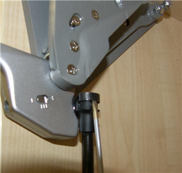
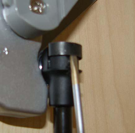
41 5.4 Lift Advanced HS / HL Fitting arms grind against the cabinet Details Cause Rectification Prevention While assembling Front adapter has twisted itself, top part (blue coloured in photo) lies sideways on the base plate (orange coloured) (Can happen while fastening the fixing screws) Loosen the screws between the parts, align the parts (see photo) and tighten the screws again, while ensuring the alignment of the parts by hand Check the alignment of the parts during fitting. 41
 Disassemble the fitting, flush fit the dowel and re-fit Dowels must be fitted flush in the flap. 2.")
42 Flaps stays tilted in front of the cabinet / Flap does not close correctly Details Cause Rectification Prevention 1. while assembling Dowel on the flap not inserted flush (see photo) Disassemble the fitting, flush fit the dowel and re-fit Dowels must be fitted flush in the flap. 2. while fitting, the flap sticks out on the top Tilt adjustment on the front adapter loosely or wrongly installed Carry out tilt adjustment and fasten the fixing screws - 3. while fitting, the flap sticks out at the bottom or parallel in front of the cabinet Tilt adjustment on the front adapter loosely or wrongly installed Closing damper too strong Carry out tilt adjustment and fasten the fixing screws Reduce the closing damper action (see page 30)

43 Fitting arm collides with the cabinet top panel when open (only HS) Details Cause Rectification Prevention Depending on the spring force, the settings of the spring force and the opening angle stop, it can happen that the fitting arm touches the top panel in the end position. Reduce the opening, if necessary, increase the spring force setting _ 43
.")
44 6 Others 6.1 Location of the contact points of the gas pressure springs The base plate of the fitting is identical for all the 4 opening versions. However the placement of the upper ball pins for the types Lift Advanced HF and HK is different from Lift Advanced HL and HS (see photo). A few times in the past, it has happened that the ball pins were wrongly installed at the factory. Meanwhile, the cause for the mistake in fitting was eliminated. The wrong placement of the upper ball pin has an effect on the opening angle of the flap. If a customer complains regarding an extremely small opening angle, the position of the upper ball pin has to be checked. 44


45 6.2 Identification of the Fittings when fitted In the versions Lift Advanced HF and Lift Advanced HL, there are variants which are suitable for different cabinet heights. Following representation should enable the user to exactly identify the fitting and check if the correct fitting has been installed. Lift Advanced HF Lift Advanced HF Lift Advanced HL mm mm mm mm mm X Lift Advanced HL 45
FABA. Installation Instructions. Conductor Bar System. Publication #FABA-03 3/1/04 Part Number: Copyright 2004 Electromotive Systems
 FABA Conductor Bar System Installation Instructions Publication #FABA-03 3/1/04 Part Number: 005-1062 Copyright 2004 Electromotive Systems 1S 100 Z Installation Instructions Contents: Basic Diagram - -
Mounting Instructions Item No.: /521/522/420/421/422
 Mounting Instructions Item No.: 541.35.520/521/522/420/421/422 Revolving Corner Unit In addition to these general mounting instructions, please refer to the fitting instructions, where the individual drilling
DICTATOR RTS Tube Door Closer
 Tube Door Closer RTS v long DICTATOR RTS Tube Door Closer The "Invisible" Door Closer The DICTATOR RTS tube door closer is built into the door and therefore is as good as invisible. The joint can only
In addition to this general mounting and adjustment instruction you need the fitting specification document, where the individual drilling dimensions
 Mounting and Adjustment Instruction for corner carrousel fitting In addition to this general mounting and adjustment instruction you need the fitting specification document, where the individual drilling
3.2.3 Rear Door Window and Quarter Window Carrier Assembly
 Tighten all bolts. Tighten bolts marked -1- and -2- in specified sequence. Tightening torque: 8 Nm Remaining bolts can be tightened in any sequence. Insert door window -3- through window recess without
Jass.Performance Low Profiles Installation Manual
 Jass.Performance Low Profiles Installation Manual What is in the box: 2x Adapter Frame 2x Outer Panels 2x Inner Panels Pushrod, Ball Joints & Brackets 2x Hella Headlights 6x Springs 4x M6x25 Cross Head
Hullavator Gas Spring Replacement (simplified)
") Hullavator Gas Spring Replacement (simplified) Some Thule Hullavators came with (original owner) lifetime warranties if you are the original owner of a defective Hullavator and can provide proof of purchase
Hullavator Gas Spring Replacement (simplified) Some Thule Hullavators came with (original owner) lifetime warranties if you are the original owner of a defective Hullavator and can provide proof of purchase
Maintenance & Parts list for:
 Maintenance & Parts list for: Industrial gun GB 2 Juni 2017 This Maintenance & Parts list for industrial gun is prepared by : Winchester Europe Service V. Parbst & Søn as a comprehensive maintenance guide
MS25 OPERATION MANUAL
 SAFETY INSTRUCTIONS SPECIFICATIONS OPERATING INSTRUCTIONS MAINTENANCE ADJUSTMENTS REPLACEMENT OF PARTS MS25 DIAGRAM MS25 PARTS LIST MS25 OPERATION MANUAL SAFETY INSTRUCTIONS Please read these instructions
Replacing the Reciprocator on the SWF Compact Series Machine (601C and 1201C)
") Follow the instructions below to replace the reciprocator in the SWF Compact series machines. The tools required can be found in the tool kit that came with the machine. Preparation 1. First, place the
Follow the instructions below to replace the reciprocator in the SWF Compact series machines. The tools required can be found in the tool kit that came with the machine. Preparation 1. First, place the
SERVICE MANUAL AND PARTSLIST
 SERVICE MANUAL AND PARTSLIST Next 20 CONTENTS WHAT TO DO WHEN... 1~3 SERVICE ACCESS FACE COVER... 4 TOP COVER... 4 BASE COVER... 5 REAR COVER... 6 FRONT COVER... 7 MECHANICAL ADJUSTMENT NEEDLE THREAD TENSION...
MM340 Installation Instructions IMPORTANT SAFETY INSTRUCTIONS - SAVE THESE INSTRUCTIONS
 MM30 Installation Instructions IMPORTANT SAFETY INSTRUCTIONS - SAVE THESE INSTRUCTIONS Please read this entire manual before you begin. Do not unpack any contents until you verify all requirements on PAGE.
Frameless Inline Door With Return QCI5263
 INSTALLATION INSTRUCTIONS Frameless Inline Door With Return QCI5263 WALL MOUNT HINGES FRAMELESS DOOR / PANEL / RETURN PANEL QCI5263 REV. 0 Page 1 Certified 06/17/2016 Parts List with wall mount hinges
INSTALLATION MANUAL FORTRESS SERIES
 Guardian Security Structures TEL 1-406-212-2334 EMAIL rg@gssdoors.com WEB www.gssdoors.com FORTRESS SERIES GENERAL INSTALLATION GUIDELINES 1. The door frame is installed using 16 bolt screws 7,5 mm in
Wooden Frame Type Instruction Manual
 Wooden Frame TypeInstruction Manual Thank you for selecting our product. Before starting installation, please read this manual thoroughly to ensure correct installation. Please keep this manual at hand
REPAIR INSTRUCTIONS. Cat. No Cat. No MILWAUKEE ELECTRIC TOOL CORPORATION. SDS Max Demolition Hammer. SDS Max Rotary Hammer
 Cat. No. 9-0 SDS Max Demolition Hammer Cat. No. -0 SDS Max Rotary Hammer MILWAUKEE ELECTRIC TOOL CORPORATION W. LISBON ROAD BROOKFIELD, WISCONSIN 00-0 8-9-0 d 000 8-9-0 d Special Tools Require Forcing
Profiform 200 Profiform 320. Operating manual
 Profiform 200 Profiform 320 Operating manual Profiform 200 / Profiform 320 Operating manual Page 1 Table of contents 1. General information Page 2 2. Profile of the Profiform sheet metal working machines
 www.hafeleindia.com www.hafeleindia.com INTRODUCTION Intuitive furniture is the need of the hour. In times like these where every extra square meter is considered as good as gold, installing versatile
INSTALLING YOUR NEW SPRING LIFT ARM KIT
 INSTALLING YOUR NEW SPRING LIFT ARM KIT 1. Measure the distance that the roof is to be raised. [If your lift system is completely non-functional, you will need to calculate or estimate this distance as
Functional movement systems for furniture in offices and public buildings. SINGLE-JOINT HINGES
 SINGLE-JOINT HINGES Functional movement systems for furniture in offices and public buildings. QUALITY CERTIFICATE Reduced to the essentials. For us, that means focusing on quality, design and function.
Mechanical Frappe Press
 Mechanical Frappe Press Operation Manual CONTENTS OPERATIONAL INSTRUCTIONS PRECAUTIONS PART NAMES INCLUDED ITEMS BASIC OPERATION MAINTENANCE REPLACEMENT PARTS Thank you for using The Frapptastic Five Mechanical
CIRRUS AIRPLANE MAINTENANCE MANUAL
 FASTENER AND HARDWARE GENERAL REQUIREMENTS 1. DESCRIPTION This section contains general requirements for common hardware installation. Covered are selection and installation of cotter pins, installation
LEG CURL IP-S1315 INSTALLATION INSTRUCTIONS
 LEG CURL IP-S35 INSTALLATION INSTRUCTIONS Copyright 2009. Star Trac by Unisen, Inc. All rights reserved, including those to reproduce this book or parts thereof in any form without first obtaining written
Fig Remove chain cover plate bolts. Fig Remove hammer member. Fig Loosen set screws at base of 12-tooth sprocket.
 Fig. 17.2. Remove chain cover plate bolts. Fig. 17.1. Remove hammer member. Fig. 17.3. Remove chain cover plate. Fig. 17.4. Loosen set screws at base of 12-tooth sprocket. Page 61 Fig. 17.5. Remove socket
Hatchback Wing Riser Kit
 Hatchback Wing Riser Kit 2015-06-11 Thank you for purchasing this PERRIN product for your car! Installation of this product should only be performed by persons experienced with installation of aftermarket
Dowelling joints with VS 600
 No. 112 Dowelling joints with VS 600 A Description Dowelling joints with round dowels (in addition to flat dowels) are part of the standard wood joints in furniture manufacture. This joint is very stable.
Assembly Instructions for Model: VMPR1
 Assembly Instructions for Model: VMPR1 Thank you for choosing a Sanus Systems Model: VMPR1 ceiling mount. The VMPR1 ceiling mount provides a unique, simplified method of ceiling mounting inverted LC/LP
4-Piece Table Tennis Table
 Item# 45-6074 4-Piece Table Tennis Table Please keep this instruction manual for future reference If you have any problems with your new product, please contact Triumph Sports USA at 1-866-815-4173, or
Hinges and Flap Fittings Information
 Information METALLAMAT Adjustment options Lateral adjustment Adjusting on concealed hinge + mm Height adjustment Via mounting plates adjusting ± 2 mm Depth adjustment Adjusting on concealed hinge + 4 mm,
Nancy s Knit Knacks LLC 4 Yard Option Upgrade Kit Assembly Instructions and User Manual
 Nancy s Knit Knacks LLC 4 Yard Option Upgrade Kit Assembly Instructions and User Manual Thank you for purchasing our 4 Yard Option (4YO) Upgrade Kit. To install this upgrade you are simply going to assemble
Series 1500 Aluminum Door Canopy
 Series 500 Aluminum Door Canopy with Sidewings It is our recommendation that you read instructions carefully prior to assembly and installation. Series 500 with Sidewings mounting bar (A) top trim (B)
Series 1100 Aluminum Door Canopy
 Series 00 Aluminum Door Canopy with Support Arms It is our recommendation that you read instructions carefully prior to assembly and installation. Series 00 with Support Arms MOUNTING BAR (A) TOP TRIM
Installation for Full Size Polaris Ranger Crew Doors
 Installation for Full Size Polaris Ranger Crew Doors Order of Installation: Heater Doors Wiper on to Windshield Windshield Top & Back Panel Note: Most of the steps in these instructions need to be repeated
S E L E C T I O N. Arm Curl. User manual
 S E L E C T I O N T H E S T R E N G T H E V O L U T I O N User manual The identification plate of the and manufacturer, affixed behind the seat, gives the following details: A Name and address of the manufacturer
METAL BLINDS. Deluxe GETTING STARTED OPTIONAL HARDWARE. A few simple tools are required: STANDARD HARDWARE
 METAL BLINDS Deluxe GETTING STARTED OPTIONAL HARDWARE A few simple tools are required: Steel Tape Measure Pencil Level Hold Down Brackets with Screws Extension Bracket Power Drill and Drill Bits Flathead
Ruby 0-4-0T Kit Assembly Instructions
 Ruby 0-4-0T Kit Assembly Instructions Ruby Parts List PART NO.& NAME QTY PART NO.& NAME QTY SHEET 1 1 Frame 2 2 Bracket 4 3 M2 x 4 Hex Head Screw 25 4 Wheelset (without eccentrics) 1 5 Wheelset (with eccentrics)
Aluminum Frame Type Instruction Manual
 Aluminum Frame TypeInstruction Manual Thank you for selecting our product. Before starting installation, please read this manual thoroughly to ensure correct installation. Please keep this manual at hand
Fig. 2 DORMA-Glas Stand/Issue 02/03 Seite/Page 1/7
 FSW Installation instructions Track rail 75 x 72 mm 1. Ceiling substructure and installation of the track rail (Fig. 1): The track rail must be bolted over its entire length (including the stacking track
Custom Wood Frame Overlay for Glass Doors Installation Instructions
 MARVEL CUSTOM WOOD FRAME OVERLAY FOR GLASS DOORS Custom Wood Frame Overlay for Glass Doors Installation Instructions Wine Cellars 6SWC 6SWCE 61WC 61WCM 66SWC (2 required) 66SWCE (2 required) Beverage Centers
EXIT DEVICE OPERATION FIRE DOOR LABELS, STRIKES AND FRAME SCREWS FOR INFORMATION CALL OR VISIT RITEDOOR.COM
 RECORD & LABELS WHAT THIS OWNER'S CAN DO FOR YOU It explains exactly how The Rite Door operates. It explains periodic maintenance requirements necessary to assure reliable operation. It explains simple
UNPACKING. Thank you for purchasing the Manual Capsule Filling Machine from KARISHMA PHARMA MACHINES.
 UNPACKING Thank you for purchasing the Manual Capsule Filling Machine from KARISHMA PHARMA MACHINES. Please take sufficient time and read this manual carefully before you start installation and operation
ALLORA SWING PANEL INSTALLATION INSTRUCTIONS
 ALLORA SWING PANEL INSTALLATION INSTRUCTIONS Before Installation Please check that your Allora Swing Panel is undamaged SEQUENCE OF INSTALLATION These instructions are also available from the Athena website:
Installation Instructions
 by Plato Woodwork Installation Instructions Plato Woodwork, Inc. 200 Third Street SW P.O. Box 98 Plato, MN 55370 www.platowoodwork.com 800.328.5924 SECTION GUIDE GETTING STARTED PAGE # Installation Methods...
CORVETTE CORVETTE REV: Made in USA U.S. PATENT #6,808,223; #6,845,547; #7,140,075; #7,059,655 and other patents pending.
 CORVETTE 2005-2006 CORVETTE 2005-2007 REV: 7-2-07 Made in USA U.S. PATENT #6,808,223; #6,845,547; #7,140,075; #7,059,655 and other patents pending. Page 1 of 12 CORVETTE C6 2005-2007 THIS KIT INCLUDES:
Ribcage Installation. Part 2 - Assembly. Back-Bone V1.06
 Ribcage Installation Part 2 - Assembly Back-Bone V1.06 Contents Section 1 Before You Get Started... 2 Included With Your Kit:... 2 Figure: A... 3 CAUTION!... 4 Note:... 4 Tools Required... 5 Section 2:
Phone # La Jolla Doors. Block Frame Installation Manual Aluminum Frame with either Vinyl or Aluminum Panels
 Phone # 800-440-8785 www.lajolladoors.com La Jolla Doors Block Frame Installation Manual Aluminum Frame with either Vinyl or Aluminum Panels Thank you for choosing La Jolla Doors In this manual you will
C70 Window Roller Repair Taken from: Heres the problem:
 C70 Window Roller Repair Taken from: http://www.volvospeed.com/vs_forum/topic/115086-how-to-c70-window-rollers-permanent-fix/ Heres the problem: This happened to two separate window assemblys on my c70
MM540 Installation Instructions IMPORTANT SAFETY INSTRUCTIONS - SAVE THESE INSTRUCTIONS
 MM50 Installation Instructions IMPORTANT SAFETY INSTRUCTIONS - SAVE THESE INSTRUCTIONS Please read this entire manual before you begin. Do not unpack any contents until you verify all requirements on PAGE.
Installation Instructions
 by Precision Screen & Security s 27040 San Bernardino Ave, Redlands, CA 92374 www.precision-screens.com TM Installation Instructions NOTE: Prior to Permanently mounting the BacTrac, insure the handle and
Assembly Instructions for model: VMPR1
 Assembly Instructions for model: VMPR1 Congratulations on your purchase! The VMPR1 ceiling mount provides a unique, simplified method of ceiling mounting inverted LCD/DLP projectors. Its low profile design
Build your own. Pack. Stages 19-22: Continue building Robi s left arm
 Build your own Pack 06 Stages 19-22: Continue building Robi s left arm Build your own All rights reserved 2015 Published in the UK by De Agostini UK Ltd, Battersea Studios 2, 82 Silverthorne Road, London
HOUSE PARTS PACKED IN HOUSE BOX PARTS IN PLASTIC BAG (HARDWARE) PARTS IN SMALL PLASTIC BAG (FLOOR CLIPS) PARTS PACKED IN BUNDLE
 PARTS IN SMALL PLASTIC BAG (FLOOR CLIPS) PARTS PACKED IN BUNDLE") Check parts against this list before starting assembly. Refer to illustrations on pages 6 and 7 to view house parts. If any shortages are found, refer to Packing Slip for claim instructions. Item 3 5 6
Check parts against this list before starting assembly. Refer to illustrations on pages 6 and 7 to view house parts. If any shortages are found, refer to Packing Slip for claim instructions. Item 3 5 6
Full Overlay Door Panel Preparation and Installation Instructions for 2175, 2115, CLR2160 Models
 Full Overlay Door Panel Preparation and Installation Instructions for 2175, 2115, CLR2160 Models www.u-lineservice.com Phone (414) 354-0300 FAX (414) 354-7905 Service & Parts Tech Lines Phone (800) 779-2547
Sales & Service. JFK - Just For Kids. sasportonline.com. 135 Forestview Road 7879 Will Rogers Blvd.
 Sales & Service sasportonline.com SA Sport (Canada) SA Sport (U.S.A.) 135 Forestview Road 7879 Will Rogers Blvd. P.O. Box 40 Fort Worth, Texas Orillia, Ontario USA 76140 Canada L3V 6H9 Telephone: (705)
SERVICE MANUAL MODEL: 13512, 14412, 15312
 SERVICE MANUAL MODEL: 13512, 14412, 15312 CONTENTS TROUBLESHOOTING... 1-3 SERVICE ACCESS (1) FACE COVER, BELT COVER... 4 SERVICE ACCESS (2) BASE PLATE... 5 SERVICE ACCESS (3) FRONT COVER... 6 SERVICE ACCESS
Installation Instruction
 Tools Needed for Assembly Stud finder (for wood stud wall) Pencil Mark Electric drill Wood Stud Wall Installation Step 1. Locate the Wood Studs Installation Instruction Drill bit (for wood stud wall) Masonry
15 Dovetail Jig. Instruction Manual. Part # 3452
 15 Dovetail Jig Instruction Manual Part # 3452 CAUTION: Please read, understand, and follow all manufacturers instructions, guidelines and owners manuals that come with your power tools. Peachtree Woodworking
RESolution V2 Manual
 RESolution V2 Manual Note for the German Manual: Yellow Bottle thick CA Pink Bottle Med CA Blue tube 5 minute Epoxy Green tube 90 Minute Epoxy Construction of the Fuselage Step 1: Cover the plan with a
INSTALLATION INSTRUCTIONS GRILLE GUARD 09-ON DODGE RAM PART #
 INSTALLATION INSTRUCTIONS GRILLE GUARD 09-ON DODGE RAM PART # PARTS LIST: Qty Description Qty Description 1 Grille Guard 8 12-1.75mm x 35mm Hex Bolts 2 Brackets (for trucks without 22 12mm x 30.1mm OD
MM750 Installation Instructions
 MM750 Installation Instructions IMPORTANT SAFETY INSTRUCTIONS - SAVE THESE INSTRUCTIONS Please read this entire manual before you begin. Do not unpack any contents until you verify all requirements on
Shepherd 210A Fingerprint Door Lock Installation Manual V1.1
 Shepherd 210A Fingerprint Door Lock Installation Manual V1.1 Hongda USA Inc. 2505 Technology Dr. #2-6A, Hayward, CA 94545, USA Phone: (510) 887-5682 Fax: (510) 372-0487 Email: info@hongdausa.com Website:
MOVENTO. The Evolution of Motion
 The Evolution of Motion is the latest advancement in concealed runner technology. It brings together all of the features, innovations and benefits that Blum has developed since first manufacturing drawer
IMPORTANT: PLEASE RETAIN THIS INSTRUCTION MANUAL FOR FUTURE REFERENCE
 IMPORTANT: PLEASE RETAIN THIS INSTRUCTION MANUAL FOR FUTURE REFERENCE 005-07 Cadillac STS Classic 3D Z, Classic Dual Weave, Classic Mesh & Classic Black Mesh Grilles B 7 HR 3 STS Classic 3D Z Grille Part
Mounting instructions SZ210 Full-frame pedestal with screw-on tube with placement hinge, for type SCHATTELLO
 This height will be made to order. Mounting instructions SZ210 Full-frame pedestal with screw-on tube with placement hinge, for type SCHATTELLO The following instructions include all information necessary
Hardware and Components:
 Hardware and Components: (A) 4X 5/16 x 1 Carriage Bolt (B) 2X 5/16 x 2-1/4 Carriage Bolt (C) 2X 5/16 x 3-1/4 Hex Bolt (D) 2X 5/16 x 3/4 Hex Bolt (E) 2X 5/16 x 1-1/4 Hex Bolt (F) 5/16 x 2-1/4 Hex Bolt (G)
MODEL T " HELICAL CUTTERHEAD INSTALLATION INSTRUCTIONS
 MODEL T27696 12" HELICAL CUTTERHEAD INSTALLATION INSTRUCTIONS For questions or help with this product contact Tech Support at (570) 546-9663 or techsupport@grizzly.com Introduction The Model T27696 indexable
Mount to the Wall INSTALLATION MANUAL
 Mount to the Wall 15 Locate the Wooden Studs This step applies to wooden stud wall installation only. Determine and mark the exact locations of two stud centers on the wall. Wooden studs should be spaced
Replacing the Reciprocator on an SWF Multi-head.
 Replacing the Reciprocator on an SWF Multi-head. Follow the instructions below to replace the reciprocator in the SWF multi-head machines. The tools required are found in the tool kit that came with the
THIS KIT INCLUDES: 8 M8-1.25X40MM BOLTS WITH WASHERS 8 M8-1.25X30MM BOLTS WITH WASHERS RIGHT AND LEFT HINGE
 Sal es@lambodoorscanada. com 2407A Kal adarave,ottawa,on K1V 8B9 THIS KIT INCLUDES: 8 M8-1.25X40MM BOLTS WITH WASHERS 8 M8-1.25X30MM BOLTS WITH WASHERS RIGHT AND LEFT HINGE 2 SHOCKS 565 PSI 2 SHOULDER
Frameless Inline Door QCI5254
 INSTALLATION INSTRUCTIONS Frameless Inline Door QCI5254 FRAMELESS DOOR / PANEL QCI5254 REV. 0 Page 1 Cer fied 06/16/2016 Parts List with wall mount hinges *Quanes may vary QCI5254 REV. 0 Page 2 Cer fied
Revised
 Indentify Non-powered panels and separate from Powered panels. Non-powered panel shown at left.. Powered panel shown at left has powerway mounted at factory. Also separate panels by surface type, width
INSTALLATION INSTRUCTIONS
 INSTALLATION INSTRUCTIONS SOLID PHENOLIC TOILET PARTITIONS 1080 DuraLineSeries Class-A Fire Rated Includes Institutional Hardware Option.67 IMPORTANT: Storage and Handling Information on last page. Review
MantelMount. TM1A Installation Instructions IMPORTANT SAFETY INSTRUCTIONS - SAVE THESE INSTRUCTIONS
 MantelMount TMA Installation Instructions IMPORTANT SAFETY INSTRUCTIONS - SAVE THESE INSTRUCTIONS TM Thank you for choosing the MantelMount television wall mount. Please read this entire manual before
ASSEMBLY INSTRUCTIONS FOR SL500A AND SL500AL
 ASSEMBLY INSTRUCTIONS FOR SL500A AND SL500AL January 2013 The SL500A is a square upright glass cabinet with a single hinged lockable door. It has five adjustable shelves plus the base. It also has an optional
FRAMELESS DOOR / PANEL WITH WALL MOUNT HINGES QCI5274
 FRAMELESS DOOR / PANEL WITH WALL MOUNT HINGES QCI5274 QCI0274 QCI5274 REV. Rev. 1 0 Page Page 1 1 Date Certified: Certified 06/16/2016 10/01/10 Parts List with wall mount hinges ITEM NO. Part # DESCRIPTION
Installation Instructions
 Supafold Slide Aside System Three Fold Room Divider Installation Instructions Distinctive Doors Ltd Supafold Slide Aside Internal Folding System IMPORTANT: Before proceeding with the installation, and
HEAVY DUTY 11 STEEL CABINET
 HEAVY DUTY STEEL CABINET ASSEMBLY INSTRUCTIONS ONE DRAWER BASE CABINET 05-206 Parts List Part No Description Qty Image ONE DRAWER BASE CABINET Part No Description Qty Image SB- Cabinet Body EH-0 Euro Hinge
Sales and Service
 OPERATION MANUAL / SPARE PARTS LIST MANUAL SEALLESS STEEL STRAPPING TOOL MODEL A333 13.2370.01 INDEX PAGE 1 SAFETY INSTRUCTIONS 2 2 WARRANTY CONDITIONS AND LIABILITY 3 3 APPROPRIATE USE 3 4 TECNICAL DATA
High Speed Air Turbine Handpiece
 OPERATION MANUAL High Speed Air Turbine Handpiece Please read this Operation Manual carefully before use and file for future reference. Handpiece should not be used with friction grip burs exceeding 18.5
DP-8 H. H. MØRCH. Instructions. Contents of the packing. Spatial requirements. Mounting the bush
 DP-8 Instructions H. H. MØRCH Contents of the packing In the packing of the tonearm you will find the arm base in which the bearings are encapsulated in a heavy body. This is the link between the moveable
SERVICE MANUAL PARTS LIST MODEL: NH40
 SERVICE MANUAL & PARTS LIST MODEL: NH40 CONTENTS What to do when... 1-3 SERVICE ACCESS Face Cover... 4 Bed Cover... 5 Free-arm Cover... 6 Front Cover... 7 Rear Cover... 8 MECHANICAL ADJUSTMENT Presser
Tilting & Swiveling Plasma/LCD Flat Panel Wall Mount Installation Guide Model: A380SM
 Tilting & Swiveling Plasma/LCD Flat Panel Wall Mount Installation Guide Model: A380SM Easy installation Built-in level for easy positioning Corrective leveling adjustments after installation Forward /
JVice Care and Maintenance Thanks for purchasing a Jvice. If properly looked after your Jvice will give a lifetime of tying pleasure.
 JVice Care and Maintenance Thanks for purchasing a Jvice. If properly looked after your Jvice will give a lifetime of tying pleasure. Although it is manufactured from highest quality materials any metal
Preference Collection and Treatment Console INSTALLATION GUIDE
 Preference Collection 5580.69 and 5580.96 Treatment Console INSTALLATION GUIDE WARNING Failure to install the 5580 as described in this installation guide may cause the unit to collapse, resulting in serious
REPAIR INSTRUCTIONS: CABLE
 The repair instructions describe replacing the Cable in the Easy Sun PARASOL Sunshade. These repair instructions are intended only for persons with experience of using the tools required. Please read the
ASSEMBLY AND CARE INSTRUCTIONS JUST FOR KIDS 355
 ASSEMBLY AND CARE INSTRUCTIONS VERSION: 8920100 (Revised 06/16) JUST FOR KIDS 355 SALES AND SERVICE spiethamerica.com Canada and International 135 Forestview Road, PO Box 40 Orillia, Ontario, Canada L3V
Heavy Duty Ceiling Tilt Mount Installation Manual
 HD-CTM-5580 Heavy Duty Ceiling Tilt Mount Installation Manual *This Installation requires a minimum of two people. For your safety: Read the complete instruction manual before starting an installation
INSTALLATION INSTRUCTIONS GRILLE GUARD RAM 1500 PART # 5058/5058-2
 INSTALLATION INSTRUCTIONS GRILLE GUARD PART # 5058/5058-2 PARTS LIST: Qty Description Qty Description 1 Grille Guard 8 12-1.75mm x 35mm Hex Bolts 2 Upper Frame Mounting s (for trucks without tow hooks
MUTO COMFORT DORMOTION XL 150/80 L 80
 MUTO COMFORT DORMOTION XL 150/80 L 80 Installation instructions - Wall mount with DORMOTION ( ) TABLE OF CONTENTS Closer overall Overview Intended use Wall requirements and fittings Safety instructions
Selekta Pro 2000 Fast assembly hinges for office and commercial furniture
 Fast assembly hinges for office and commercial furniture 99 The program opening angles 180 and 270 with pre-mounted pan-head screws with eccentric height adjustment ± 2 mm with eccentric overlay adjustment
Sabre Series 2 Inspired Design Precision Engineering
 Sabre Series 2 Inspired Design Precision Engineering USER INSTRUCTIONS Thank you for choosing the Keencut Sabre Series 2. Every effort has been made to bring you a precision engineered product with the
Frameless Inline Door QCI5250
 INSTALLATION INSTRUCTIONS Frameless Inline Door QCI5250 FRAMELESS PANEL / DOOR / PANEL QCI0249 REV. 3 Page 1 Certified 10/12/12 Parts List with pivot hinges *Quantities may vary. QCI0249 REV. 3 Page 2
EmagiKit. Privacy Pod Plus. Quiet. Easy. Affordable. INSTRUCTIONS ASSEMBLY
 EmagiKit Privacy Pod Plus Quiet. Easy. Affordable. INSTRUCTIONS ASSEMBLY DIMENSIONS AND COMPONENTS 47 47 Ceiling Unit 2-B 2-L 2-R Glass Door Corner Trim Door Handle 90 Adjustable Height Work Surface 1-B
Preference Collection 5543 Central Console INSTALLATION GUIDE
 Preference Collection 5543 Central Console INSTALLATION GUIDE WARNING Failure to install the 5543 as described in this installation guide may cause the unit to collapse, resulting in serious injury to
INSTALLATION INSTRUCTIONS
 INSTALLATION INSTRUCTIONS HIGH PRESSUE LAMINATE (HPL) TOILET PARTITIONS 1030 TrimLineSeries 1040 DesignerSeries Includes continuous hardware option.65. IMPORTANT: Storage and Handling Information on last
Functional movement systems for furniture in offices and public buildings. SINGLE-JOINT HINGES
 SINGLE-JOINT HINGES Functional movement systems for furniture in offices and public buildings. QUALITY CERTIFICATE Reduced to the essentials. For us, that means focusing on quality, design and function.
VACUSEAL MODEL 300 & 400
 VACUSEAL MODEL 300 & 400 G L HOT TUB PRODUCTS 2 Toelles Road, Suite 13 Wallingford, CT 06492 860-469-2580 www.hottubproducts.com J G F H H K E D C I A P B 10 9 8 7 6 5 4 3 2 1 0 0 1 Figure 1 2 3 4 SPAS
Power Train Lift Max. Capacity: 1,250 lbs.
 655 EISENHOWER DRIVE OWATONNA, MN 55060 USA PHONE: (507) 455-7000 TECH. SERV.: (800) 533-6127 FAX: (800) 955-8329 ORDER ENTRY: (800) 533-6127 FAX: (800) 283-8665 INTERNATIONAL SALES: (507) 455-7223 FAX:
WARNING. Read and become familiar with this manual BEFORE operating unit.
 Covered by one or more of the following patents: 3,828,942 5,368,429 5,586,619 5,984,605 7,556,464 7,726,901 Other patents pending. OPERATOR S MANUAL For Model 439 WARNING Read and become familiar with
Instruction Manual. Manual Furniture Mover. Note: Owner/Operator must read and understand this instruction manual before using the furniture mover.
 Instruction Manual Manual Furniture Mover Note: Owner/Operator must read and understand this instruction manual before using the furniture mover. I - Contents 1. Application 2 Specifications 3.Assembly