The Structural Use of Timber
|
|
|
- Allan Horn
- 5 years ago
- Views:
Transcription

1 Malcolm Jacob James Harrington Bill Robinson The Structural Use of Timber Handbook for Eurocode 5: Part 1-1
2 Malcolm Jacob James Harrington Bill Robinson The Structural Use of Timber Handbook for Eurocode 5: Part 1-1
3 COFORD Department of Agriculture, Food and the Marine Agriculture House Kildare Street Dublin 2 Ireland First published in 2018 by COFORD ISBN: Title: The Structural Use of Timber - Handbook for Eurocode 5: Part 1-1 Authored by: Malcolm Jacob, James Harrington and Bill Robinson Citation: Jacob, M., Harrington, J., Robinson, B The Structural Use of Timber - Handbook for Eurocode 5: Part 1-1. COFORD, Department of Agriculture, Food and the Marine, Dublin. COFORD, 2018 All rights reserved. No part of this publication may be reproduced, or stored in a retrieval system or transmitted in any form or by any means electronic, electrostatic, magnetic tape, mechanical, photocopying, recording or otherwise, without prior permission from COFORD.
4 Dedicated to the memory of James Harrington in recognition of his contribution to the structural use of Irish timber and his work in timber standards.
5 The Structural Use of Timber Handbook for Eurocode 5: Part 1-1 Contents Foreword by the Minister...i Introduction...iii Disclaimer...iv Conventions and abbreviations...iv Conventions...iv Abbreviations...iv 1 General Eurocode 5 in the Eurocode family National Annexes and nationally determined parameters Eurocode 1 - Actions on structures Eurocode 0 Basis of structural design The Construction Products Regulation (CPR) Execution of timber structures Solid timber and glued solid timber products General Solid timber Finger jointed solid timber Glued laminated timber and glued solid timber Glued laminated timber (glulam) Glued solid timber Glulam with large finger joints Block glued glulam Deviation in sizes Correction of sizes due to moisture content change Laminated veneer lumber Deviation in sizes Correction of sizes due to moisture content change Cross-laminated timber The harmonised product standard EN Deviation in sizes Correction of sizes due to moisture content change Adhesives for glued timber products Type 1 and Type 2 adhesives Sub-classes Glue line thickness Maximum test temperature Adhesive application Moisture contents of timber for glued joints at assembly Effect of change in moisture content on floor, roof and wall plates...17
6 The Structural Use of Timber Handbook for Eurocode 5: Part Deviation from straightness Design assumptions Product straightness requirements Wood-based panel products used as structural elements General Classification of wood-based panel products Performance characteristics Characteristic strength, stiffness and density values Plywood OSB, particleboard and fibreboard Wall constructions Floor constructions Effects of material variability, load-duration and moisture content Partial factors for material property γ M Load-duration classes Service classes Strength modification factors k mod for service and load-duration classes Deformation modification factors k def for service class Durability of timber, timber products and wood-based panels Use classes Natural durability of timber Specifying treatment Service classes Fasteners and connectors General Dowel-type fasteners General Load-carrying capacity Resistance to corrosion Connectors General Split ring, shear plate and toothed plate connectors Punched metal plate fasteners (PMPF) Resistance to corrosion Horizontally and vertically in-plane loaded structural plate elements General Horizontal plate elements Vertical plate elements Methods of analysis Connections... 37
7 The Structural Use of Timber Handbook for Eurocode 5: Part Trusses fabricated with punched metal plate fasteners General Design, fabrication and erection S.R. 70, Timber in construction - Eurocode 5 - Trussed rafters EN Requirements CE Marking Annex A Tables Solid timber and glued timber products Annex B Tables - Adhesives in glued timber products Annex C Tables Wood-based panel products Annex D Tables Effects of material variability, load duration and moisture content Annex E Tables - Fasteners and connectors Annex F Timber species Annex G Loadings and actions Annex H Non-contradictory complementary information Annex I European standards in categories Annex J References... 81
8 Foreword i Foreword In line with the growing level of harvest from Irish forests, Irish sawmilling output has increased substantially, and was close to one million cubic metres in Kiln dried, graded structural timber has accounted for most of the increase, and amounts to more than half of sawmill output. Allied to the increasing levels of sawnwood production in Ireland, there is growing realisation of the many benefits of wood in construction, including a material that facilitates rapid, modern and modular construction, and one that has signifcant potential to reduce the level of greenhouse gas emissions associated with traditional construction methods. Timber buildings, also of course, store carbon over extended periods and this role in climate change mitigation can only increase over the coming decades. Underpinning the use of timber in construction is Eurocode 5 Part 1-1 and associated CEN loading and product standards. Since the first edition of the COFORD Handbook on structural design to Eurocode 5, published in 2006, a large amount of new information has become available which is needed by a structural engineer when designing timber buildings. The many amendments to product standards resulting from the introduction of the Construction Products Regulation in July 2013 are included. In addition a strong emphasis has been given to providing more technical information, mainly through tables, in this edition making the handbook more user friendly. Information on cross laminated timber has been added to coincide with the spectacular rise in the use of this wood product in timber construction. A new section gives information on the adhesives and the related product standards which are common to many glued timber products, including CLT. I am confident that this handbook will help many more structural engineers and specifiers who are new to timber construction to specify with confidence timber and timber products in their client s buildings. Andrew Doyle TD, Minister of State for Forestry Department of Agriculture, Food and Marine January 2018
9
10 Introduction iii Introduction Eurocode 5 was first published as a European standard in 2004; amendments appeared in 2006, 2008 and Major reviews of most parts of all the Eurocodes have already been done by CEN TC 250. Working groups and project teams under CEN TC 250/SC 5 are busily developing the so called secondgeneration Eurocode 5, with the new Eurocodes scheduled to appear in Since 2004 many of the product standards and related standards have been amended, some extensively. The Construction Products Regulation came into effect in 2013 and this led to more revisions of most of the harmonised European product standards. The rapid increase and extraordinary development in the use of cross-laminated timber (CLT) took place after Thus, no particular rules for the design of CLT members are included in the current Eurocode 5. Facing the task of designing a structural timber member or a complex timber structure, the structural engineer has Eurocode 5 to hand and a lot of other information. The aim of this handbook is to summarize some of that other information into a single source. Like the first edition of the handbook, this second edition is not a commentary on Eurocode 5 Part 1-1 dealing with every topic; instead the focus is on providing useful information on the numerous solid timber and wood-based panel products and, also, on fasteners and connectors. Rather than wait the three to four years for the second-generation Eurocodes to be published, it was decided to prepare this second edition now, in This allows the many changes that have already taken place since 2004 to be addressed in this edition. A strong emphasis has been given to providing more tables in this second edition. The aim is that once familiar with the text, the user may be able to simply use the tables for everyday work. Generally, the requirements in the current EN are not repeated here, except in some instances. One of the exceptions is the inclusion of the tables on the effects of material variability, loadduration and moisture content. Many of the requirements for adhesives for the different types of joint are common to finger jointed timber, glued laminated products and cross laminated timber, and so information for the designer and the specifier are dealt with in a new separate section. The production requirements for curved glulam or curved cross laminated members are not included; for these the designer is referred to EN and EN Fire can start, develop and spread in any building and designing the structure to continue to provide support and separation for the required fire resistance period is essential. EN deals with the design of timber structure in normal conditions; the design of structural timber in a fire situation is covered in a different part, EN As in the first edition, this handbook only covers design in normal conditions. References to a current European standard are generally without the year of publication; however, the relevant current standards related to the use of EN are listed in different categories in Annex J, where the year of publication is given.
11 iv The Structural Use of Timber Handbook for Eurocode 5: Part 1-1 Disclaimer Although care has been taken to ensure, to the best of our knowledge, that all data and information contained in this handbook are accurate to the extent that they relate to either matters of fact or accepted practice or matters of opinion at the time of publication, the authors assume no responsibility for any errors in or misinterpretations of such data and/or information or any loss or damage arising from or related to their use. Conventions and abbreviations Conventions The following conventions are followed: Blue text is used for references to headings, tables or pages in this handbook Ordinary text is used for references to clauses, tables or equations in the EN or document which is being discussed in a paragraph Italics are used for references to clauses, equations or tables in EN All of the European Standards referred to are also Irish Standards. For brevity, the letters I.S. have been omitted from the standard names but are included in the lists of standards in Annex I Abbreviations AVCP CEN CPR CUAP DoP EAD EOTA ETA ETAG NA NDP NPD OJEU Glulam LVL CLT OSB MDF PMPF RoI Assessment and Verification of Constancy of Performance European Committee for Standardisation Construction Products Regulation Common Understanding on Assessment Procedures Declaration of Performance European Assessment Document European Organisation for Technical Approvals European Technical Approval or European Technical Assessment European Technical Approval Guidelines National Annex Nationally Determined Parameters No Performance Determined Official Journal of the European Union (commonly referred to as the OJ) glued laminated timber laminated veneer lumber cross-laminated timber oriented strand board medium density fibreboard punched metal plate fastener Republic of Ireland
12 General 1 1 General 1.1 Eurocode 5 in the Eurocode family There are ten Eurocodes covering the structural design of structures and the actions on them: EN 1990 Eurocode 0: Basis of Structural Design EN 1991 Eurocode 1: Actions on structures EN 1992 Eurocode 2: Design of concrete structures EN 1993 Eurocode 3: Design of steel structures EN 1994 Eurocode 4: Design of composite steel and concrete structures EN 1995 Eurocode 5: Design of timber structures EN 1996 Eurocode 6: Design of masonry structures EN 1997 Eurocode 7: Geotechnical design EN 1998 Eurocode 8: Design of structures for earthquake resistance EN 1999 Eurocode 9: Design of aluminium structures EN 1990 gives the basis of structural design for the design codes (EN 1992 to EN 1999); EN 1991 gives the actions on structures (loadings) to be used with the design codes. The design codes are spilt into a number of parts (usually at least three) dealing with various design aspects; Part 1-1 gives general rules and rules for buildings, Part 1-2 gives information on fire design, Part 2 covers bridges and Part 3 deals with specific items. EN 1995 (i.e. Eurocode 5) consists of three separate sections; Parts 1-1, 1-2 and National Annexes and nationally determined parameters All of the Eurocodes mentioned so far are required to have National Annexes (NA). While each standard is exactly the same in each member state, it is allowed to have some nationally determined parameters (NDP) which are included in a National Annex. In the foreword of each Eurocode the clauses through which national choices are allowed are listed; notes within the main body of the Eurocode indicate where the choices are permitted and recommendations are usually given where there are options. Other European standards exist to provide support to the design standards; these include topics such as testing, strength grading, preservative treatment and various product standards. A number of these standards can be supported by other standards for example some of the testing standards related to timber grading have standards covering the calculation of characteristic values. All the standards sit within a committee framework; committees deal with amendments, revisions and the development of standards. Going from bottom to top there is usually a technical or task group (TG), then a working group (WG) and above this the plenary committee; the TGs report to the WGs and the WGs to the plenary committee, all of which is overseen by the European Commission. Eurocode 5 is simply another design standard within the European family with its own supporting standards etc. It is similar to the steel, concrete and masonry codes in this context.
13 2 The Structural Use of Timber Handbook for Eurocode 5: Part Eurocode 1 - Actions on structures EN 1991 gives the actions, including the many types of loads, and thermal actions, which building structures and bridges may be required to support. The requirements for combinations of these actions are given in EN EN 1991 has ten separate parts: EN , Actions on structures - Part 1-1: General actions - Densities, self-weight, imposed loads for buildings EN , Actions on structures - Part 1-2: General actions - Actions on structures exposed to fire EN , Actions on structures - Part 1-3: General actions - Snow loads EN , Actions on structures - Part 1-4: General actions - Wind actions EN , Actions on structures - Part 1-5: General actions - Thermal actions EN , Actions on structures - Part 1-6: General actions - Actions during execution EN , Actions on structures - Part 1-7: General actions - Accidental actions EN , Actions on structures - Part 2: Traffic loads on bridges EN , Actions on structures - Part 3: Actions induced by cranes and machinery EN , Actions on structures - Part 4: Silos and tank 1.4 Eurocode 0 Basis of structural design This is the leading Eurocode and establishes principles and requirements related to: Ultimate Limit State (safety) Serviceability Limit State (deflection, vibration etc.) Durability The basis of their design and verification. It also gives some guidelines for structural reliability. Eurocode 0 makes certain assumptions regarding personnel including that design is undertaken by appropriately qualified and experienced personnel and that factory and site personnel also have the appropriate level of skill and experience. It also assumes that adequate levels of supervision and quality control are provided for execution of the works in design, factories and site. The Eurocode further assumes that the construction products and materials are as specified in the relevant design standards, execution, material or product standards and that the structure will be adequately maintained and used in accordance with the design assumptions. Design conditions are divided into four classifications: Persistent this refers to conditions of normal use Transient this refers to temporary conditions e.g. during execution or repair Accidental this refers to exceptional conditions e.g. fire, explosion, impact or the consequences of local failure Seismic this is where structures are subject to seismic events.
14 General 3 Actions or loads are classified as: Permanent e.g. the self-weight of components or structures, fixed equipment and indirect actions caused by shrinkage or uneven settlement Variable - e.g. imposed loads on floors walls, roofs, wind loads and snow loads Accidental e.g. explosions or vehicles. Guidance is given on the nature of different characteristic actions as well as how to modify different variable actions and combinations of variable actions: The combination value is represented as Ψ 0 Q k The frequent value is represented as Ψ 1 Q k The quasi-permanent value is represented as Ψ 2 Q k. The combination value is usually used for persistent or transient situations (fundamental combinations i.e. the common design case). The Ψ 0 Q k factor is applied to the secondary variable actions, each variable action is considered as the primary action in turn with the other variable loads considered as secondary loads. For accidental designs, the Ψ 1 Q k variable load is used for the primary variable action and Ψ 2 Q k for the secondary variable loads; again each variable load is considered as a primary load. The use of Ψ 1 for the primary variable load, rather than Ψ 2 is a national choice and is specified in the National Annex to EN The Construction Products Regulation (CPR) Following the introduction of the Construction Products Regulation (CPR) in July 2013 it is now mandatory that all construction products which are covered by a harmonised European standard have a Declaration of Performance (DoP) and are CE marked. If a manufacturer has a European Technical Assessment (ETA) he must also have a DoP and CE mark his product. Under the CPR, if there is no harmonised product standard and/or the manufacturer does not have an ETA, then he cannot issue a DoP or CE mark the product. The first harmonized standard for timber products was EN Wood Based Panels for Use in Construction, published in The following are the principal harmonized European product standards for timber products relevant for designing to EN : EN 13986:2004+A1:2015, Wood-based panels for use in construction Characteristics, evaluation of conformity and marking. EN 14080:2013, Timber structures Glued laminated timber and glued solid timber Requirements. EN :2016, Timber structures Strength graded structural timber with rectangular cross section Part 1: General requirements (at time of writing this EN has not been included in the OJEU). EN 14250:2010, Timber structures Product requirements for prefabricated structural members assembled with punched metal plate fasteners. EN 14374:2004, Timber structures Structural laminated veneer lumber Requirements.
15 4 The Structural Use of Timber Handbook for Eurocode 5: Part 1-1 EN 14545:2008, Timber structures Connectors Requirements. EN 14592:2008+A1:2012, Timber structures Dowel-type fasteners Requirements. EN 14915:2013, Solid wood panelling and cladding Characteristics, evaluation of conformity and marking. EN 15497:2014, Structural finger jointed solid timber Performance requirements and minimum production requirements. EN 16351:2015, Timber structures: cross laminated timber requirements (at time of writing this EN has not been included in the OJEU). The Official Journal of the European Union and the European commission publishes a list of harmonised standards on www. ec.europa.eu. The requirements for ETAs can be found on the European Organisation for Technical Approvals (EOTA) website; ETAs are based on European Assessment Documents (EAD) which are slowly replacing the ETAGs (European Technical Approval Guidelines), though some ETAGs are still valid. European Technical Approvals were originally a way of providing a uniform specification for products where there was no European or harmonised standard; it was a voluntary assessment procedure and companies did not have to go down the ETA route. However, once a company has an ETA then they must have a DoP and CE mark their product. The CPR lays down seven Basic Requirements for Construction Works and states that construction products must be fit for their intended use and take into account the health and safety of persons involved in the works: 1. Mechanical resistance and stability 2. Safety in case of fire 3. Hygiene, health and the environment 4. Safety and accessibility in use 5. Protection against noise 6. Energy economy and heat retention 7. Sustainability of natural resources. The basic works requirements are reflected in the essential characteristics which are contained in the CE marking section of the harmonised specification. The CE mark cannot be applied until the manufacturer has drawn up a Declaration of Performance (DoP). The DoP gives the performance levels of the essential characteristics that the manufacturer wishes to declare. It should list all the essential characteristics; if no performance level is declared then NPD (no performance determined) may be placed against the essential characteristic, but the performance of at least one essential characteristic is required to be declared. All product standards tend to have marking requirements but harmonised product standards have both marking requirements and CE marking requirements. The manufacturer has sole responsibility for the DoP and CE marking. However, under certain circumstances other economic operators (a term which relates to the supply and distribution of construction products and can include manufacturers, importers, distributors and authorised representatives) have to take over these responsibilities. Importers may only put construction products on the market that comply with the CPR. They should ensure that the manufacturer has drawn up a DoP and has affixed the CE mark. The importer should check
16 General 5 that the DoP has been drafted in accordance with the model in Annex III (amended) of the CPR, and that the product bears a mark allowing its identification and that of the manufacturer. Importers also need to ensure that instructions and safety information accompany any product. They should also ensure that the conformity of the product is not changed while under their control e.g. by storage or transport conditions. Distributors need to make sure that, where required, the construction product has the CE mark and other appropriate documents required by the CPR (including the DoP); this extends to product identification and details of the manufacturer. The specific obligations of manufacturers can apply to importers and distributors where they place a product on the market under their own name or trademark or where they modify a construction product already placed on the market in such a way that the DoP is affected. Care also needs to be taken in relation to the effects of such a change on the requirement of the AVCP and the CE mark. An authorised representative should not draw up any technical documentation (including a DoP) and may only perform the duties set out in a written agreement between the manufacturer and the representative. However, the authorised representative should keep copies of the technical documentation (including the DoP and CE mark) and make such documentation available where required, especially for the national surveillance authorities. The declared performances in the DoP and CE mark should be the same; one performance cannot be declared in one without being declared in the other and of course, the values should match. A DoP can be generic and placed on a website. In some cases, this means that the DoP may not give much useful information; e.g. as in the case of roof trusses where the calculations and drawings (required by EN to be provided by the manufacturer) would provide essential information. Standards have specific requirements and these should be fulfilled as well as the requirements for providing a DoP and CE mark. The DoP and CE mark declare performance levels of the essential characteristics but it is up to the user/specifier to ensure that these levels are adequate for the intended use. 1.6 Execution of timber structures At time of writing, there are standards for the execution of steel structures (EN 1090) and concrete structures (EN 13670), but none for timber structures. A draft execution standard is currently being developed by WG 9, a working group under CEN TC 250/SC 5. In general, it is proposed to give the minimum requirements for fabrication, assembly, transport, and erection of timber structures, which are designed in accordance with EN 1995, to ensure that a completed structure is as the designer intended in terms of its strength, stability, and durability. To achieve the above it is proposed to include in the standard: The permitted tolerances for fabricated elements including for: member dimensions, fastener hole sizes and location, cutting and machining, and components such as floor, roof and wall elements The allowed erection tolerances at a reference moisture content The requirements for moisture content control of timber and timber products during execution The requirement for the preparation of fabrication method statements The requirements for the preparation of method statements for transport, handling and erection of the structural members and components A list of information which should be provided in a project specification on execution.
17 6 The Structural Use of Timber Handbook for Eurocode 5: Part Solid timber and glued solid timber products 2.1 General Solid timber and glued solid timber products are generally used for beams, columns (or posts), ties, beam-columns and frames, and trusses. These glued solid timber products include: Finger jointed solid timber Glued laminated timber Laminated veneer lumber (LVL) Cross laminated timber (CLT) When the above structural units form a continuous layer within the external envelope of a building (i.e. in external walls, roofs and suspended ground floors) the designer of the whole envelope needs more performance characteristics than those required just for the structural design of the unit. These additional characteristics include: Water vapour permeability Air permeability Thermal conductivity Airborne sound insulation Sound absorption. Manufacturers of wood-based panels usually determine and declare these additional performance characteristics because it is more than likely the panel may be used as a layer within a wall, floor or roof construction. Information and requirements for wood-based panel products are in Section 3. The current harmonised European product standards for solid timber and glued solid timber products are: EN , Timber structures Strength graded structural timber with rectangular cross section Part 1: General requirements EN 15497, Structural finger jointed solid timber Performance requirements and minimum production requirements EN 14080, Timber structures Glued laminated timber and glued solid timber Requirements EN 14374, Timber structures Structural laminated veneer lumber Requirements EN 16351, Timber structures Cross laminated timber Requirements (status as a harmonised EN is imminent). To design a structural timber member in a building to comply with Eurocode 5, the engineer needs to know the strength and stiffness properties and the density of the proposed material, and the cross-section dimensions and lengths of the products normally available on the market. For example, a beam in a finished building has normally been designed and specified by the designer, made by a manufacturer and installed by a builder. Using the available standards or technical specifications, the designer/specifier specifies the beam; the builder buys the beam from the manufacturer.
18 Solid timber and glued solid timber products 7 If the beam is straight and of uniform cross-section the designer/specifier typically specifies at least the required strength and stiffness of the material - usually using strength classes the breadth and depth the allowed maximum deviations from the specified dimensions the allowed maximum deviations from straightness the maximum moisture content of the timber at delivery to the building site the use class in accordance with EN 335 where preservative treatment is required. The manufacturer makes such a beam in accordance with the requirements of a harmonised product standard or a European Assessment Document, declares the various values in a DoP, CE marks it and sells it. The strength and stiffness values for the materials/products listed above are not included in EN The information the designer needs for each product is presented below. 2.2 Solid timber EN is a harmonised product standard which governs the strength grading of structural timber; the standard was revised and published in 2016, but at time of writing has not been referenced in the OJEU, which means that the previous version ( A1: 2011) still applies. The standard gives some rules for visually graded timber; national standards (such as I.S. 127) are still required for visual strength grading. Machine grading usually assigns timber directly to a strength class while visually graded timber is usually graded to either general structural (GS) or special structural (SS) grade and then assigned to a strength class using EN A manufacturer may produce a special grade (for example TR26) and give the performances of the essential characteristics in a Declaration of Performance provided this is undertaken according to EN For the vast majority of designs the design characteristic properties for solid timber will be taken from EN 338. Strength and stiffness values and densities for three different strength class systems, C classes, T classes and D classes are found in EN 338 in Tables 1, 2 and 3, respectively. According to 6.2.2, a timber population may be assigned to a strength class if the following values equal or exceed the strength class values in Table 1, 2, or 3: the characteristic values of edgewise bending (or tension parallel-to-grain) strength the mean modulus of elasticity in bending or tension parallel-to-grain the characteristic density. A summary of the strength class system is given in Table A.1. Solid timber boards may be machine graded directly into one of the C, T, or D strength classes. The above three values are determined from tests results and apart from shear strength and some tension perpendicular to grain strengths, which are constant values, all the remaining values in Tables 1, 2 or 3 in EN 338 are calculated using equations in Table 2 in EN 384; Table A.2 demonstrates how the values are determined for strength class C16. Home-grown softwood in the Republic of Ireland is most commonly graded into strength classes C14, C16 and C18 (about 95 % into C16) and imported whitewood is generally available in strength classes C16 and C24 and by special order in C27. Strength and stiffness values and densities for the
19 8 The Structural Use of Timber Handbook for Eurocode 5: Part 1-1 above strength classes are included in Table A.3. The values in Tables 1, 2 and 3, and Tables A.1, A.2 and A.3 are for timber with an average moisture content of 12 % (equilibrium moisture content at 20 C and 65 %RH). Dried solid softwood timber with an average moisture content of 20 % is referred to as dry timber (according to EN ). The target size is defined in EN 336 as the cross-section size corrected to 20 % moisture content and is the size that is specified by the engineer in the structural specification or on the structural drawings. The engineer also specifies the tolerance class according to EN 336 as either Tolerance class 1 or 2; Table A.4 shows the permitted deviations in the two tolerance classes. For solid structural timber members in both Service class SC 1 and SC 2 environments, the target breadth and depth of timber (with a rectangular cross-section) are used by the engineer when calculating the section modulus or the moment of inertia. The characteristic strength, stiffness and density values used by the engineer in his calculations are normally those given for the selected strength class in one of the tables in EN 338. Justification for using these values, which are stated as being for solid timber with an average moisture content of 12 %, is given below. In the ultimate limit state (where k crit is equal to 1,0), the ultimate bending stress is required to be less than the design bending strength, f m,d, which is found from ffff ",$ = kkkk "'$ γγγγ ).ffff ",+ where k mod is a strength modification factor for service classes and load-duration classes γ M is a partial factor for a material property: 1,3 for solid timber f m,k is the characteristic bending strength for a strength class from EN 338 In Table 3.1 in EN (also given in Table D.4), k mod has the same value for service class SC 1 and SC 2 for all load-duration classes. Therefore, according to EN , the design bending strength should be taken as being the same for solid timber with average moisture contents of 12 or 20 %. Madsen et al [1] found that the effect of moisture content in bending was highly strength dependant, and for strengths of less than 20 N/mm 2, bending strengths decreased as the moisture content reduced. This is the opposite of what was assumed in the past: i.e. bending strength increased as moisture content decreased. The ultimate bending capacity of a timber member should theoretically reduce with decrease in moisture content due to shrinkage and the resulting smaller cross-section size, but most engineers ignore this in their calculations nor is it a requirement of EN to take the reduction in size into account. For a change of moisture content from 20 to 12 %, ignoring the size reduction is effectively allowing an increase in design bending strength of approximately 6 %. Madsen et al also found in [1] that the mean modulus of elasticity values (E-values) increased with decreasing moisture content, but found practically no change in the bending stiffness because the increase in E-value was offset by the reduction in moment of inertia due to shrinkage. The latter appears to justify the use of the E-values from the tables in EN 338 for solid timber in Service class SC 1 without correcting the cross-section size for the change in moisture content from 20 to 12 %. The permitted deviations from target sizes for softwood and hardwood species are given for two tolerance classes, 1 and 2, in Tables 1 and 2, respectively in EN 336. Table A.4 shows the permitted deviations in the two tolerance classes. The target size of a piece of sawn or prepared square-edged timber is defined as the specified cross-section size at the reference moisture content, 20 %. To check if the cross-section dimensions of a piece of solid softwood timber are within the permitted
20 Solid timber and glued solid timber products 9 deviations, the dimensions must first be corrected to the reference moisture content, 20 %, assuming a 0,25 % decrease or increase in dimension for every 1 % change in moisture content unless a more accurate dimension change rate is known for the timber. Hardwoods should be adjusted by 0,35 % for every 1 % change in moisture content. Example The floor joists in a floor are specified as 44 mm thick and 200 mm wide and Tolerance class 2 (according to EN 336). The average moisture content of one piece is 16 % and its thickness and width are measured as 42 and 197 mm, respectively. Is the target size within the permitted deviations of Tolerance class 2? The target thickness and width at 20 % moisture content are calculated and found to be 42,4 and 199,0 mm respectively. From Table A.4, it can be seen the target width is within the permitted deviation (200 1,5 = 198,5) but not the thickness (44 1 = 43). 2.3 Finger jointed solid timber The performance and minimum production requirements for structural finger jointed timber are given in the harmonised product standard EN The standard covers finger jointed timber made from sixteen softwood species (including Norway spruce, European silver fir (Fir), Sitka spruce, Scots pine and European larch) and poplar. The full list of species is given in and in Table F.1 in Annex F. The finger jointed timber is required to consist of only one species, but Norway spruce and Fir may be considered as being one species. The solid timber used to make finger jointed timber is required to be strength graded to EN into one of the strength classes in EN 338 or a manufacturer s specific strength class. The strength and stiffness values and density values of the finger jointed timber are the same as those for the strength class of the timber from which it is made. The characteristic bending strength of the finger joints is required to be equal to or to exceed the characteristic bending strength of the solid timber. Both the strength class of the timber and the characteristic bending strength of the finger joints are declared in the DoP. The finger joints are required to be tested in accordance with Annex C in EN If the timber is preservative treated, only treatments according to 4.5 in EN which do not affect the strength and stiffness properties of the timber should be used. The recommended finger lengths and geometries for the finger joints are given in Annex G as well as the moisture content requirements. The moisture content of the two pieces being joined must not differ by more than 5 % and must be between 7 and 18 %. 2.4 Glued laminated timber and glued solid timber Glued laminated timber (glulam) members with rectangular cross-section are manufactured in accordance with EN by gluing kiln-dried planed solid timber pieces together in a controlled factory environment. The standard covers glued laminated timber made from sixteen softwood species (including Norway spruce, Fir, Sitka spruce, Scots pine and European larch) and poplar. The full list of species is given in and in Table F.1 in Annex F. EN gives the performance requirements not only for glued laminated timber but also for glued solid timber, glulam with large finger joints and block glued glulam. Each of the structural glued timber products are defined below.
21 10 The Structural Use of Timber Handbook for Eurocode 5: Part Glued laminated timber (glulam) Each member is made up of at least two laminations. The laminations have thicknesses from 6 to 45 mm and may comprise two boards side by side Glued solid timber Each member is made up of two to five laminations and having maximum depth or breadth of 280 mm. The laminations may have thicknesses greater than 45 mm and up to 85 mm, and all have either the same strength class or manufacturer specific strength class. Glued solid timber manufactured in accordance with the minimum production provision in EN is suitable for use in Service class 1 or 2 environments only Glulam with large finger joints One member is made from joining two glulam members together with large finger joints. The cut for each tapered finger is parallel with the depth of the joined members. The angle between the lamination length directions in both joined members may be from 45 to 90 degrees. The fingers must be at least 45 mm long. Glulam with large finger joints manufactured in accordance with the minimum production provision in EN is suitable for use in Service class 1 or 2 environments only Block glued glulam Member with rectangular cross section made up of two or more glulam members bonded together with a gap filling adhesive (an adhesive which has been tested with a 2 mm thick glue line). Curved members or members with non-uniform cross-sections are also made by many manufacturers; however, the information in this handbook is for straight pieces with uniform cross-section only. Glulam members are generally manufactured to meet the strength and stiffness value and density requirements of the glulam strength classes given in EN Two sets of glulam strength classes are given, one set for homogeneous glulam and the other for combined glulam. In homogeneous glulam, the solid wood laminations all have the same strength class, whereas in combined glulam, laminations with two to three different strength classes may be used. The glulam strength class notation is explained by using an example: Glulam strength class GL 24c: The letters GL denote glulam class. In this class, the characteristic bending strength (about the strong y-axis) is 24 N/mm 2 and the lower-case letter c denotes it is combined glulam. When the glulam is homogeneous the letter h is used instead of c. Characteristic strength and stiffness values and densities for each glulam strength class are found in Tables 4 and 5 in EN for combined and homogeneous glulam, respectively. Table A.5 gives values for the most commonly used glulam strength classes for both combined and homogeneous glulam. The strength and stiffness values and density values for glued solid timber are the same as those for the solid timber from which it is made. C24 glued solid timber is commonly used for floor beams and rafters which are visible in the finished building, and generally has a planed finish on all sides. EN is a harmonised EN and therefore the manufacturer should produce a DoP, and CE mark the glued timber products Deviation in sizes The maximum deviations of corrected sizes from nominal sizes for glulam, glulam with large finger joints and block glued glulam are given in Table A.6, and for glued solid timber in Table A.7.
22 Solid timber and glued solid timber products Correction of sizes due to moisture content change If the moisture content of the glued laminated product differs from the reference moisture content, 12 %, the corrected depth or width may be calculated using expression (6) in of EN and the swelling/shrinkage factors in Table 14. The expression is: llll "#$ =llll & 1+kkkk uuuu +,- uuuu & where l COR l a k is the corrected dimension in mm. is the actual size is the swelling/shrinkage factor (called deformation factor in Table 14 - a misnomer) k = 0,0025 in perpendicular-to-grain directions (average of radial and tangential) k = 0,0001 in parallel-to-grain direction (above are valid for coniferous wood and poplar within 6 25 % MC range) u ref is the reference moisture content = 12 % u a is the actual moisture content in % measured according to Annex G in EN Table A.8 shows corrected dimensions for a range of depths or widths of glulam assuming the nominal dimension is the dimension at the reference moisture content, 12 %. 2.5 Laminated veneer lumber Currently there are two European standards for the use of LVL, EN and EN However, in a proposed amended EN, pren (published for the CEN Enquiry process in May 2016) it is proposed to combine and update the contents of both current ENs into a new harmonised product standard. Publication of the new standard, or an amended version of it, is imminent (the designer is advised to check the current status of the pren). The two current standards and the pren are: EN 14279: A1: 2009, Laminated veneer lumber (LVL) Definitions, classification and specifications EN 14374: 2004, Timber structures Structural laminated veneer lumber Requirements pren 14374: 2016, Timber structures Laminated veneer lumber (LVL) Requirements. The current EN was prepared by CEN TC 112 Wood-based panels, the technical committee which prepares the ENs for wood-based panels, whereas the current EN was prepared by CEN TC 124 Timber structures. It appears that when LVL is manufactured for use as floor or roof panels (or decking) the assessment and verification of constancy of performance (AVCP) should be carried out using I.S. EN 13986, the same standard that is used for the AVCP of plywood, orientated strand board, particleboard and fibreboard panels. However, LVL members which are subjected to bending moment about the weak-axis (called flatwise bending ), are also included in the scope of EN and the AVCP may be carried out using the latter because it is a harmonized product standard. Having one harmonized product standard for all LVL products, as proposed in the pren, will remove the current overlap between the two standards.
23 12 The Structural Use of Timber Handbook for Eurocode 5: Part Deviation in sizes The maximum deviations of corrected dimensions from nominal sizes for laminated veneer lumber from 4.3 in EN 14374: 2005 are given in Table A.9 and from 6.8 and Table 1 in the draft pren (May 2016) in Table A Correction of sizes due to moisture content change Swelling/shrinkage factors are not required to be declared in the current EN In the draft pren in 6.8 swelling/shrinkage values are required to be: Expressed by the product type, or Tested according to EN 318 and declared as 95 % quantiles referring to EN 318. LVL is manufactured with and without cross layers. Swelling/shrinkage is reduced by cross layers. Swelling/shrinkage factors for one of manufacturer s products are given in their product literature. These are given in Table A.11 to show the designer the order of the factor he/she would expect to find for LVL of the two different types. 2.6 Cross-laminated timber The use of cross-laminated timber has increased dramatically since the publication of Eurocode 5 in This material is not included in the current EN , nor are particular rules given for its structural use. However, proposed rules for the design of CLT members are currently being developed for the second-generation Eurocodes and the product standard EN was published in Publication of the latter has not yet been listed in the OJEU, but once it has it will become a harmonised EN. Manufacturers are currently using the European Assessment Document EAD [2] as the basis for obtaining European Technical Assessments for their CLT products. CLT is mainly used for floor, roof and wall plates. A plate is defined here as a structural element which has no protrusions on either of the two largest parallel flat surfaces. The stresses and strains occurring in a CLT plate depend on how it is loaded. The plates are usually loaded mainly in one direction at a time, but can also be loaded in two directions at the same time. A CLT floor plate supporting vertical loads is loaded in a direction perpendicular to the CLT, whereas a CLT wall plate acting as a shear wall in a building is loaded in the plane of the CLT. The strength and stiffness of the CLT when subjected to load in either of the above directions is usually calculated from (a) the strength and stiffness values of the solid timber boards used to make up the layers, and (b) the geometry of the cross section. It is assumed that: the glued joints are rigid and the shear and tensile strength of the bonding is always stronger than that of the timber being joined, and the characteristic bending and tensile strengths of the finger joints in the boards are stronger than those of the timber. The manufacturer may use solid timber boards which have been graded into a strength class in EN 338, either from Table 1 (C classes) or Table 2 (T classes) or he may test samples of the solid timber and determine the characteristic strengths and mean stiffnesses from the test results. Some of the strength and stiffness properties of the timber needed to calculate the strength and stiffness of the CLT are not
24 Solid timber and glued solid timber products 13 provided in the EN 338 tables, and these must be determined from test results or from values that can be assumed without testing. The requirements for the latter are currently given in the EAD The additional values include: For CLT loaded in the perpendicular-to-plate direction Characteristic shear strength perpendicular to the grain Mean shear modulus perpendicular to the grain (according to EAD : G 9090,mean = 50 N/mm 2 may be used). In European Technical Approvals or Assessments (ETAs) for CLT the following three declared values are found to be generally lower than those given in Tables 1 or 2 in EN 338 Characteristic tension strength perpendicular to the grain (for load perpendicular to plate) Mean shear modulus parallel to grain (for load in plane of plate) Characteristic shear strength parallel to grain (for load in plane of plate). A review of some current ETAs shows that some manufacturers are testing the modulus of elasticity parallel to the grain of the graded solid timber and are taking advantage of the higher mean values determined from the test results (higher than those in EN 338). With no harmonized product standard in place, manufacturers have so far obtained ETAs for their CLT products in order to comply with the CPR. Most recent assessments have been made in accordance with EAD An ETA for a product is valid for 5 years after it is obtained and so ETAs to EAD will continue to be valid for up to 5 years after EN is published in the OJEU. Because of its alternating arrangement of longitudinal and cross layers, the bending stiffness about an axis parallel to the cross layers (the y-axis), is greater than that about an axis parallel to the longitudinal layers (the x-axis). For verifications in the ultimate limit state the section modulus may be calculated using the net cross-section ignoring the shear flexibility of the cross layers, whereas for the serviceability limit states the shear flexibility is taken account of in the effective cross-sectional values. The simplified method in Annex B of EN (also known as the Gamma method) can be adapted to CLT cross sections. The method in the current EC5 is for mechanically jointed beams and for crosssections with two or three parts connected to each other with fasteners and can be used to calculate: In the ultimate limit state: Maximum normal stresses at top and bottom edges of the cross-section using Equations (B.7) and (B.8) Maximum shear stress in the middle, or next to middle longitudinal layer using Equation (B.9) Maximum horizontal load on a fastener using Equation (B.10) Effective bending stiffness using Equations (B.1 to B.6). The slip modulus for the ultimate limit state is K u which equals 2/3 K ser. In the serviceability limit state: Effective bending stiffness using Equations (B.1 to B.6). The slip modulus for the serviceability limit state is K ser.
25 14 The Structural Use of Timber Handbook for Eurocode 5: Part 1-1 The Gamma method in Annex B in EN may be applied to a CLT cross-section by replacing the fasteners between the connected parts with the flexible cross layers in the CLT element. The term s i /K i in Equation (B.5) is replaced by d i /G. b. The amended equation (B.5) becomes γγγγ " = [1 + ππππ (.EEEE ".AAAA ".dddd " (GGGGG GGGG ".llll ( )] 34 where d i G b is the thickness of the cross layer boards is the shear modulus of the cross layer board perpendicular to the grain is the width of the glued joint between the cross layer board and the longitudinal board d 1 is the thickness of the cross layer board between the top and second layers of longitudinal boards, d 3 is the thickness of the cross layer board between the second and bottom layers of longitudinal boards. The same value of G equal to 50 N/mm2 is recommended in EAD when calculating the effective stiffness in both limit states. whereas in the original Equation (B.5) s i K i is the spacing of the fasteners is the slip modulus of the fastener connection s 1 and K 1 are for the connection of part 1 to part 2 and s 3 and K 3 are for the connection of part 3 to part 2. Using the amended γ i in Equation (B.10) the maximum horizontal shear force perpendicular to a single cross layer board may be calculated. The design shear strength in this case is the characteristic rolling shear strength f v,9090,k (or f R,k ) multiplied by k mod and divided by γ M. For cross sections with more than three longitudinal layers, for example seven or nine layer CLT, a modified Gamma method (called the extended Gamma method) may be used. The latter and the alternative shear-flexible Timoshenko beam method are described in [3]. The Timoshenko beam method is preferred in the CLT floor plate design software provided by one of the manufacturers. A review of the content of some of the more recently obtained ETAs for CLT products shows the variations between products made by each manufacturer. Table A.13 compares some of the dimensions and specifications of two manufacturers for their CLT products. In both EAD and in the new EN 16351, CLT may be used in Service classes 1 and 2 environments The harmonised product standard EN The new standard gives the requirements for straight and curved structural CLT with or without large finger joints and applies to CLT used in Service class 1 or 2 environments made with: Coniferous species or poplar (list of species is given in Table F.1) Strength graded solid timber boards to EN to 60 mm thick solid timber layers up to a total depth of 500 mm At least 3 layers of which 2 are solid timber Some adjacent layers bonded parallel to the grain
26 Solid timber and glued solid timber products 15 All boards edge-bonded in each layer, or less than 6 mm wide gaps between board edges Some wood-based panel layers with thicknesses of 6 to 45 mm (without edge bonding). The adhesives and bonding requirements for finger joints in solid timber boards, joints between layers, board to board edge joints and large finger joints are included in the standard. Large finger joints between CLT elements are covered by the standard where the joined pieces: Have the same cross section and layups; and only solid timber layers Are 51 to 345 mm thick; outermost layers are not less than 17 mm thick Have finger joints with at least 45 mm long fingers Are joined with the grain directions in the surface boards lining up (with x-axis). Section 5 in EN gives the requirements for the product CLT and its components Deviation in sizes The maximum deviations of corrected dimensions from nominal sizes for CLT from in EN are given in Table A.12. No maximum deviations are given for width of CLT cross-section, length of CLT element, or deviation from straightness. NOTE: In in EAD the manufacturer is required to declare the manufacturing tolerances of the CLT element in accordance with the applicable specifications of EN 336. In one of the manufacturers ETAs assessed to the above EAD, the declared tolerances on the cross-section dimensions are within the maximum deviations for tolerance class 2 in EN 336, however, it is not stated in the EAD or in the ETA how the dimensions should be corrected to a reference moisture content or to what reference moisture content. The reference moisture content in EN 336 is 20 % and is 12 % in EN Correction of sizes due to moisture content change If the actual moisture content of the CLT differs from the reference moisture content, 12 %, the corrected depth or width for unhindered moisture induced dimension change may be calculated using expression (4) in of EN The expression is: aaaa "#$ =aaaa &. (1 + kkkk "#$,-. uuuu $/0 uuuu & ) where a cor a a k cor,α is the corrected dimension in mm. is the actual size is the swelling/shrinkage factor (called deformation factor in a misnomer) k cor,90 = 0,0024 in perpendicular-to-plane direction (average of radial and tangential) k cor,0 = 0,0002 in parallel-to-plane direction (above are valid for coniferous wood and poplar within 6 25 % MC range) u ref is the reference moisture content = 12 % u a is the actual moisture content in % measured according to Annex G in EN In the latest working draft of the proposed new rules for the design of CLT in the second-generation Eurocode 5 (May 2017), different values for the swelling/shrinkage factor may be taken for swelling/
27 16 The Structural Use of Timber Handbook for Eurocode 5: Part 1-1 shrinkage in the x and y-axis directions parallel to the plane as follows: k cor,x = 0,0002 in parallel to plane in the x-axis direction k cor,y = 0,0004 in parallel to plane in the y-axis direction, where the x-axis is parallel to the length of the CLT element and y-axis parallel to the width. 2.7 Adhesives for glued timber products Because of the overlap between the requirements for adhesives in the individual European product standards for finger jointed solid timber, glued laminated products and cross-laminated timber, the adhesive products are considered together in this one sub-section. Each of the product standards require that the adhesives used should provide durable bonds throughout the lifetime of the structure for the required Service class and that each adhesive can be assigned to an adhesive class in EN 301, EN 14525, or EN Adhesives from the three families of adhesives (below) are referred to in the glued product standards: 1. Phenolic and aminoplastic polycondensation adhesives (MF, MUF, PRF, UF) (I.S. EN 301) 2. One component polyurethane adhesives (PUR) (EN 15425) 3. Emulsion polymer isocyanate adhesives (EPI) (EN 16254). EN 301, EN and EN specify the performance requirements of the adhesives in the three families. In each of these standards, adhesives are assigned to adhesive classes in a Table 1 (same table number in each). It is important to note that these standards apply to the adhesive only and not to the glued timber joint. For example, in the tests to determine the tensile shear strength, the timber test specimens are always made from beech. It is the adhesive that is being tested not the glued joint and the requirements in these standards apply to type testing of the adhesives only. Adhesives meeting the requirements of these standards are adequate for use in load-bearing timber structures only if the bonding process is carried out in accordance with the requirements of the harmonised product standard. The bonding process requirements for CLT are, for example, given in Annex I in EN Thirteen adhesive classes are specified in Table 1 in EN 301, seven in Table 1 in EN and nine in Table 1 in EN Type 1 and Type 2 adhesives In each family of adhesives, an adhesive is either a Type 1 or Type 2 adhesive. Types 1 and 2 do not have the same meaning in all of the adhesive standards. In EN 301 and EN Type 1 adhesives are stated as being suitable for use in Service classes 1, 2 and 3; in EN Type 1 adhesives are those suitable for use in Service classes 1 and 2; In all three standards Type 2 adhesives are only suitable for Service class 1 (Roman numerals for the 1 and 2 in Types 1 and 2 are not used in this handbook ordinary numbers are used instead) Sub-classes Adhesives in the three standards are further allocated to sub-classes related to their use. These subclasses are defined in each standard and summarised in Table B.1. The reader should note that the subclasses general purpose (GP) and finger jointing (FJ) do not have the same definition in each standard.
28 Solid timber and glued solid timber products Glue line thickness In each standard, a glue line is defined as being thick if its thickness lies between 0,3 and 2,0 mm, and as close contact if not greater than 0,1 mm. Thicknesses of 0,1; 0,2; 0,3; 0,5; 0,6; and 1,5 mm are included. To achieve a close contact glue line the pieces being joined must be plane and clamped together with a clamping pressure of 0,8 ± 0,1 N/mm 2 without grooves or spacers Maximum test temperature The maximum temperature in test conditions is limited to 50, 70, or 90 C Adhesive application For those phenolic and aminoplastic adhesives which comprise two parts (such as a resin plus a hardener), and the two parts are to be mixed before application, the class name includes the capital letter M. If the parts may be applied separately and are mixed in the bonding process the letter S is included. Emulsion polymerized isocyanate adhesives are always applied in a mixed state and one component polyurethane adhesives comprise only one part and so the letters M and S do not appear in the class designation. The adhesive classes for the three families of adhesive are given in Table B.2. The classes of adhesive used for the different joints in a glued product are declared in the product s Declaration of Performance. The designer and specifier can use Tables A.9 and A.10 to check the adhesives are appropriate for their intended use Moisture contents of timber for glued joints at assembly The requirements for a range of moisture content and moisture content difference for the different types of joint in the various glued solid timber products at time of assembly are summarized in Table B Effect of change in moisture content on floor, roof and wall plates Wall, floor and roof structural units (or plates) are readily made using CLT. LVL may be used in two forms, either as (a) a single structural member, or (b) as a floor or roof decking. Floor and roof decking may also be made using glulam planks (glulam installed on its side) and solid timber pieces may be nailed or stapled (with hardwood dowels or pegs) together to make wall units and floor and roof units. The effects of swelling of wood particularly in the tangential and radial directions because of change in moisture content need careful consideration in all the above uses, and definite measures must be taken to accommodate such swelling. Because of their cross layered construction, the changes in width due to change in moisture content are less for CLT panels and LVL with cross layers (see Table A.11 for LVL). The designer/specifier should specify the required maximum and minimum moisture contents of the specified solid timber or glued solid timber products at time of delivery to the building site. 2.9 Deviation from straightness Design assumptions To verify the stability of members in EN , the engineer may use the calculation methods in the Eurocode. The stability of columns or struts subjected to either compression or combined compression and bending may be verified using and the lateral torsional stability of beams subjected to bending
29 18 The Structural Use of Timber Handbook for Eurocode 5: Part 1-1 or combined bending and compression may be verified using In expression (6.29) in the values of the factor β c are only valid for columns whose straightness is within the limits given in section 10 in 10.2 (1). Likewise, in 6.3.3, expression (6.34) may only be used to determine the value of the factor k crit if the straightness of the beam is within the same limits. In 10.2 (1) the deviation from straightness midway between the supports is limited to L/500 for glued laminated timber and LVL and L/300 for solid timber, where L is the member length or the effective length Product straightness requirements The designers and specifiers need to check the relevant harmonised product standard or European Technical Approval or Assessment to see if the solid timber or solid timber product they specify is required to be manufactured with a straightness within the above limits and if not the limit needs to be specified on the drawings or in the project specification. For solid timber bow is defined as deviation from straightness when the piece is bent about the weak axis; and spring when bent about the strong axis. Limits in EN and I.S. 127 for bow and spring are given as maximums over a 2 m length. In EN for classes C18, T11 and below, bow is limited to 20 mm and spring to 12 mm for both visually and machine graded solid timber; for higher classes bow and spring are limited to 10 and 8 mm, respectively. For visually graded solid timber according to I.S. 127, bow and spring are limited to 20 and 12 mm, respectively, for General Structural grade (GS) and limited to 20 and 8 mm, respectively, for Special Structural grade (SS). The timber used in finger jointed solid timber is required to be strength graded according to EN and so the above limits apply to finger jointed timber as well. The maximum deviation from straightness (referred to as longitudinal warping) for glued laminated timber, glulam with large finger joints and block glued glulam is limited to 4 mm over a length of 2 metres. That is equivalent to a limit of L/500, i.e. the same as the limit in 10.2(1). No limits on the maximum deviation from straightness are required for glued solid timber in EN 14080, or for LVL in EN or EN It is proposed to include limits on deviation from straightness for structural members in the Execution standard.
30 Wood-based panel products used as structural elements 19 3 Wood-based panel products used as structural elements 3.1 General The wood-based panel products in this section include those used as panels in a load-bearing timber frame floor, roof and wall constructions. The term construction used here means the whole floor, roof or wall, including all the layers which make up the total thickness. These constructions may be subjected to loads applied in directions normal or parallel to the plane of the construction. Normally, only some of the layers or pieces within the constructions are designed to resist the loads applied to them. For example in a shear wall, the timber frame and the panel layers fastened to it provide resistance to horizontal load applied parallel to the plane of the wall (normally referred to as racking resistance). Panels are subjected to different environments depending on their location within the thickness of a construction. At any point in time, the moisture content of a wood-based panel depends on the humidity and temperature history in its local environment. Some local environments vary considerably over time and others very little. Panels fastened to the top of floor joists in an internal suspended floor are normally in an environment where the change in the humidity of the air over time is relatively small. In contrast, panels fastened to the outer face of the timber frame in external wall and roof constructions are often in local environments where the humidity of the air is higher and fluctuates considerably over time. For structural purposes three different local environments are defined in EN Wood-based panels in these environments are described as being in one of, Service class 1, 2 or 3. The average moisture content of softwoods in the three classes is given in Table D.3, but the equivalents for the different wood-based panel materials are not given in EN The designer should obtain the average moisture contents of wood-based panel materials in service classes SC 1 and SC 2 from the panel manufacturer. The average moisture content of an oriented strand board type OSB/3 is estimated to be 16,5 % in service class SC 2, for example, - lower than that for the softwood from which it has been made. In EN there are no limits on the moisture content of wood-based panels fastened to the outer face of external timber frame walls and roofs, however a limit of 18 % is required in some national standards in Europe. Limits of 20 % for solid timber products and 18 % for wood-based products are for untreated products and are to prevent colonisation and damage by wood-destroying fungi. Where a wood-based panel is installed on the outer face of the timber studs in a timber frame external wall and is adjacent to a ventilated cavity, the designer should obtain the maximum average moisture content allowed for untreated panels from the panel manufacturer. The performance characteristics of wood-based panels are normally given for structural use in dry, humid, or exterior conditions. In EN dry, humid, or exterior conditions are defined as being those corresponding with service classes SC 1, SC 2, or SC 3, respectively. Where panels fastened to the outer face of the timber frame in a wall construction are used to provide all or part of the racking resistance of a wall, the designer must decide which local environment and hence service class is applicable. The design lateral load-carrying capacity of a panel-to-timber connection for a nail, or staple is adjusted for moisture content through the k mod factor. The values of this factor for plywood are given in Table D.4, and for other wood-based panels in Table D.5. It can be seen that no values for k mod are given in Table D.5 for wood-based panels in service class SC 3 environments. Table C.1 shows where the different wood-based panel products are typically used as structural elements in buildings.
31 20 The Structural Use of Timber Handbook for Eurocode 5: Part Classification of wood-based panel products It appears product standards for wood-based panel products were prepared by the CEN technical committee TC 112 and its working groups at different times and by different experts. As a result, there is no consistent overall classification system which covers all of these products. There are types and classes and types within classes and some types are classes. In an effort to present the information on these panel products in this handbook in a more coherent way the following system is adopted: 1. Plywood, OSB, particleboard and the fibreboards, hardboard, medium board and MDF are all called products 2. Within each product, variations of the product are allocated to classes 3. Variations within a class are called sub-types (dry, humid and exterior are use condition sub-types) 4. Sub-types include those (a) Suitable for use in the three environments: dry, humid and exterior (b) For all load-duration classes, or limited to some (c) Load-bearing or heavy-duty load-bearing. Note: Sub-type is deliberately used rather than type, because in some of the classifications in the product standards, the different classes are called types, for example in section 4 in EN 300: 2006 oriented strand boards are classified according to four Types, OSB/1, OSB/2 and so on. The classification of OSB, particleboard and fibreboard panels which are used as structural elements in either dry or humid conditions is summarized in Table C.2. Fibreboards are manufactured from lignocellulosic fibres (mainly softwood) and are produced using either wet or dry production processes. Fibreboards produced by wet processes are classified in EN 316 and in EN 622-2, -3, -4 and -5 according to the density of the panel material. Table C.3 shows this classification. Fibreboards are classified further according to additional properties and applications; the classification system and the related symbols are shown in Table C.4. Examples MBH.LA2 - High density medium board (MBH) for load-bearing use (L) in dry conditions (no symbol) in all load-duration categories (A) and a heavy-duty load-bearing board (2). MDF.HLS Medium density fibreboard (MDF) for use in humid conditions (H) for load-bearing use (L) and for instantaneous or short-term load-durations (S). 3.3 Performance characteristics The performance characteristics for solid wood panels, plywood, LVL, OSB, particleboard, cementbonded particleboard and fibreboard are given in EN 13986: A1: This standard gives the performance characteristics required for each of nine variations of use of the wood-based panel products in construction. Of these, the five of most interest to the designer using EN 1995, are those used as structural components:
32 Wood-based panel products used as structural elements For internal use in dry conditions (SC 1) 2. For internal (or protected external) use in humid conditions (SC 2), and as wood-based panels used in dry or humid conditions as structural: 3. Floor decking on joists 4. Roof decking on joists (or rafters) 5. Wall sheathing on studs. Tables 1 and 2 list the required performance characteristics for the uses in 1 and 2 above and Table 7 lists those required for the uses in 3, 4 and 5 in one table. In Table 7 the requirements for durability (moisture resistance) in clause 5.6 are not required for use in dry conditions and those for strength and stiffness under point load are required for floor and roof joists only. All the listed requirements in Tables 1 and 2 are included in Table 7 (If a small number of superscripts and footnotes had been added in Table 7, Tables 1 and 2 could have been omitted from the standard). EN also sets out the requirements for assessment and verification of constancy of performance (AVCP) and for CE marking of wood-based panels. The means of determining each characteristic are given in each table by reference to the relevant clause in section 5 in EN In Table C.5 the tests required or other determining methods are shown for each of the performance characteristics listed in Table 7 in EN Table C.5 covers plywood, LVL, OSB, particleboard (resin bonded and non-extruded) and fibreboard; the designer/specifier is referred to Table 7 and the relevant clauses in EN for solid wood panels and cement-bonded particleboard. For all of the panel products in Table C.5 the bending strengths and stiffnesses about the major and minor axes are tested according to EN 310 and the test results expressed according to EN The resulting values must exceed those given in the relevant table in the panel product standard. For example for an 11 mm thick OSB/3 panel, the resulting values must exceed those in Table 4 in EN 300 for the thickness range >10 to <18 mm; for a 12 mm thick P5 particleboard, the resulting values must exceed those in Table 7 in EN 312 for the thickness range >10 to 13 mm. The relevant standard for fibreboard is EN 622 and each different product has its own part as follows: hardboards EN 622-2, Medium boards EN 622-3, and MDF EN For an 8 mm thick HB.HLA1 hardboard panel, the resulting values (of bending strength and stiffness) must exceed those in Table 6 in EN for the thickness range >5,5 mm; for a 12 mm thick MDF.HLS panel the resulting values must exceed those in Table 6 in EN for the thickness range >9 to 12 mm. The minimum bending strengths and bending stiffnesses required in the product standards for values from tests according to EN 310 and EN for 12 mm thick panels of OSB/3, P5 particleboard, and MDF.HLS and MDF.RWH are compared in Table C.6. The above bending strengths and stiffnesses (determined from tests according to EN 310) should not be used for design purpose; the values for use in calculations are considered under the next heading. 3.4 Characteristic strength, stiffness and density values Plywood The characteristic strength, stiffness and density values of a plywood can be provided by a manufacturer in two ways:
33 22 The Structural Use of Timber Handbook for Eurocode 5: Part Each of the strength and stiffness values for a plywood can be determined from tests according to EN 789 and characteristic values determined from the test results using EN 1058, or a combination of calculated values according to EN and values from test results, or 2. A plywood can be assigned to a class according to EN 636 using Tables 1 and 2 and the characteristic strength and mean stiffness values obtained using EN Using the second method a plywood is named by assigning the following properties: (a) Out-of-plane bending strength about the y-axis, f m,0 (b) Out-of-plane bending strength about the x-axis, f m,90 (c) Modulus of elasticity for bending about the y-axis, E m,0 (d) Modulus of elasticity for bending about the x-axis, E m,90, into two bending strength classes using Table 1 and two modulus of elasticity classes using Table 2. The above bending strengths and moduli of elasticity are determined from bending tests according to EN 310 and EN with results expressed according to EN Example Example (not real) bending strength and modulus of elasticity values from tests and test results are assigned using Table 1 and 2 in Table C.7. The calculation values are then obtained from the following tables in EN Table 2 Bending, tension and compression strengths from the bending strength F-class Table 3 Mean moduli of elasticity for bending, tension and compression from the modulus of elasticity E-class Table 4 Shear strengths and stiffnesses from the mean density according to EN 323. The full set of calculation values for the example is shown in Table C OSB, particleboard and fibreboard The characteristic strength, stiffness and density values are given in various tables in EN : 2001 for the following load-bearing and heavy-duty load-bearing classes of OSB, particleboard and fibreboard: Oriented strand boards OSB/2, OSB/3 and OSB/4; to EN 300: 2006 Particle boards P4, P5, P6, and P7; to EN 312: 2010 Hardboard HB.HLA2; to EN 622-2: 2004/AC: 2005 Medium board MBH.LA2; to EN 622-3: 2004 Medium density fibreboards MDF.LA, MDF.HLS; to EN 622-5: The current versions of the product standards have all been revised since 2001; EN : 2001 is in need of revision. Values for medium boards MBH.HLS1 and MBH.HLS2 and medium density fibreboard MDF.RWH should be included. The latter is currently sold on the market in RoI as a panel suitable for providing racking resistance, but without a value for the shear modulus for load applied in a direction parallel to the face (panel shear) the designer cannot calculate one part of the total horizontal deflection (i.e. shear deflection of the panel).
34 Wood-based panel products used as structural elements 23 The characteristic strength, mean stiffness and density values for the above product classes are presented in Tables C.9 to C.14 (inclusive) but for a smaller range of thicknesses than included in the tables in EN These tables (C.9 to C.14) also show which values are missing. If the designer needs these missing values he should contact the product manufacturers. 3.5 Wall constructions A wall construction may be an internal or external wall. In both, the wall typically supports floor and wall loads applied vertically to the top of the wall. In this case the timber studs are axially loaded in compression and the panels fixed to the studs provide lateral support to the slender stud members. If the wall provides racking resistance (acts as a shear wall) the panels are subjected to shear forces in the plane of the panels and the wall studs are subjected to axial loads and resist out-of-plane buckling of the panels. Panels within external wall constructions generally have more than one function. For example, the hygrothermal performance of the construction depends on the water vapour diffusion resistance of the different layers making up the construction. Many designers require panels with low values of water vapour diffusion resistance fixed to the outer face of the wall studs. Panels on the outer face of the studs with better thermal resistance may also be specified. The primary structural requirements of a panel in a timber frame wall construction are its resistance to in-plane loads (racking) and the embedment strength of the panel material for laterally loaded doweltype fasteners. The lateral deflection of the panel partly depends on the shear stiffness of the panel material; and the out-of-plane buckling resistance of the panel depends on the 5-percentile modulus of elasticity of the material for bending about an axis parallel to the wall studs. In Methods A and B in EN out-of-plane buckling is limited by requiring that the clear distance between wall studs is less than or equal to 100 t, where t is the panel thickness. In all methods of calculating the racking strength of wall constructions, the maximum horizontal load the wall can resist is directly proportional to the characteristic lateral load-carrying capacity of the panel-to-timber connection for the fastener used to connect the panels to the timber frame members. To calculate the capacity the designer needs to know the characteristic embedment strength for a fastener in the selected wood-based panel material. Equations are given for calculating the embedment strength in in EN for plywood, hardboard, particleboard and oriented strand board for nailed panel-to-timber connections where the nail head diameter is at least twice the diameter of the nail. The equations are summarized in Table E.5. It can be seen that for plywood the embedment strength depends on the density of the plywood and the diameter of the fastener, whereas for hardboard, particleboard and OSB it depends on the diameter of the fastener and the thickness of the panel, but not on the density. Due to the manufacturing process, some panel materials do not have a uniform density through the thickness of the panel and this is the reason the embedment strength depends on the thickness. The same equations as above can be used for calculating the lateral load-carrying capacity of stapled panel-to-timber connections, where the leg diameter is taken as the square root of the product of the cross-section dimensions and when the pull-through capacity is equal to or greater than that provided with a head with a diameter of 2 d, where d is the nominal diameter of the nail. For medium boards (MB) and medium density fibreboards (MDF) no equations are given in EN However, in 3.5 (1)P wood-based panels are required to comply with EN and a
35 24 The Structural Use of Timber Handbook for Eurocode 5: Part 1-1 manufacturer has a number of options when it comes to declaring racking resistance. To determine racking strength and stiffness of a timber frame wall according to EN the alternatives in may be used; in summary, these are: 1. The characteristic racking strength F Rd,max,k and the mean stiffness R mean may be determined from tests according to EN 594 and these values may be used for walls with the same components and arrangement as those used in the tests 2. The characteristic lateral load-carrying capacity of a panel-to-timber connection for a particular combination of fastener and thickness of the panel product may be determined from test results. In 2 above the selection and preparation of the test specimens and joined pieces are done according to EN 1380; the test loading procedure is carried out according to EN 26891, and the characteristic lateral load-carrying capacity is determined from the test results using EN The manufacturer may also carry out tests and declare the characteristic embedment strength. The tests are done according to EN 383 and the characteristic value is determined from the test results using EN The characteristic embedment strength is only valid for the type and diameter of the fastener and the strength class of the timber specimens used in the tests. If C24 timber was used in the tests, for example, the designer would have to adjust the characteristic load-carrying capacity declared by the manufacturer when fastening the panel product to C16 timber studs. The characteristic lateral loadcarrying capacity of a nailed panel-to-timber connection can then be calculated using the equations in in EN In summary, to compare the design racking resistance and mean stiffness of two timber frame shear walls made with different wood-based panels, the designer needs the following values for each: Characteristic lateral load-carrying capacity of the panel-to-timber connection for the same one fastener type, or Characteristic embedment strength for one fastener type Shear stiffness or shear modulus of the panel when resisting load in the plane of the panel in the horizontal direction Bending stiffness, EI, for bending out-of-plane of the panel about an axis parallel to the wall studs. 3.6 Floor constructions Where a wood-based panel is used as floor or roof decking, it is required to support a uniformly distributed load or a concentrated load according to EN for the specified category of imposed loading. The concentrated load test and assessment methods are specified in EN
36 Effects of material variability, load-duration and moisture content 25 4 Effects of material variability, load-duration and moisture content 4.1 Partial factors for material property γ M The design strength of a material or the design resistance of a connection are found by multiplying the characteristic value by the strength modification factor k mod and dividing it by the partial factor for material property γ M : ffff " =ffff $. $ &'( ) * ; FFFF," =FFFF ". $ &'( ) * Table D.1 gives the partial factor for material property adjusted to include the requirements of the Irish NA to EN Load-duration classes Load-durations are defined in Table D.2 and examples of types of loading are included in the third column. The table includes the recommendations in the Irish NA to EN Service classes The three service classes defined in in EN are shown in Table D Strength modification factors k mod for service and load-duration classes Values of k mod for different combinations of service class and load-duration class are given for solid timber, glulam, LVL, plywood and CLT in Tables D.4 and for OSB, particleboard and fibreboard in Table D.5. Note 1: The values given for CLT are those recommended in the most recent draft rules submitted to CEN TC 250/SC 5 at time of writing. Note 2: For many of the product classes in Table D.5 values of k mod are only given for Service class 1; none are given for Service class Deformation modification factors k def for service class Values of the modification factor k def for solid wood, glulam, LVL, plywood and CLT in different service classes are given in Tables D.6 and D.7. Note: The values given for CLT are those recommended in the most recent draft rules submitted to CEN TC 250/SC 5 at time of writing.
37 26 The Structural Use of Timber Handbook for Eurocode 5: Part Durability of timber, timber products and wood-based panels Treating timber with a preservative can be an effective low-cost method of extending the service life of timber and timber products. However, some timbers have a natural durability that may be perfectly well suited for their intended use. There are many sources of information that can help a designer decide on whether treatment is necessary or if the natural durability of the timber is adequate. Environments are allocated to Use classes in EN 335 Durability of wood and wood-based products - Use classes: definitions, application to solid wood and wood-based products. A designer must first determine the environment where the component is to be used. The use classes are defined below. 5.1 Use classes Use class 1 (UC 1) - wood or wood-based products are inside a construction and not exposed to the weather and wetting. Insect attack might be possible. In this environment the moisture content of solid wood is such that the risk of attack by surface moulds or by staining or wood-destroying fungi is insignificant (the wood would have a moisture content of a maximum of 20 % in any part of the component for practically the whole of its service life). Examples include internal joinery, dry roofs and internal floor timbers. Use class 2 (UC 2) - wood or wood-based products are under cover and not exposed to the weather (especially rain) but where occasional, but not persistent wetting may occur. Condensation of water on the surface of the wood may occur; insect attack might be possible. In this environment the moisture content of solid wood occasionally exceeds 20 %, either in the whole or only in part of the component. This might allow attack by wood-destroying fungi. Examples include roof timbers where there is a risk of wetting, timber frame external wall panels and ground floor joists. Use class 3 (UC 3) - wood or wood-based products are above ground and are exposed to the weather. There are two possible sub-classes in this use class: Use class 3.1 (UC 3.1) where the wood or wood based product will not remain wet for long periods; water will not accumulate. Use class 3.2 (UC 3.2) where the wood or wood based product will remain wet for long periods and water may accumulate. In this environment the moisture content of solid wood can be expected to exceed 20 % frequently, and thus it will often be liable to attack by wood-destroying fungi. Examples include external joinery, decking boards and joists and cladding. Use class 4 (UC 4) - wood or wood-based products are in direct contact with the ground or fresh water.
38 Durability of timber, timber products and wood-based panels 27 In this environment the moisture content of solid wood would be expected to exceed 20 % permanently and would be liable to attack by wood-destroying fungi. The above-ground (or above-water) portion of certain components, for example fence posts, may be attacked by wood-boring beetles. Examples include fence posts, poles and sleepers. Use class 5 (UC 5) - wood or wood-based product are permanently or regularly sub-merged in salt or brackish water. In this environment the moisture content of solid wood can be expected to exceed 20 % permanently. Attack by invertebrate marine organisms is the principal problem, particularly in the warmer waters where organisms such as Limnoria spp., Teredo spp. and Pholads can cause significant damage. The above water portion of certain components, for example harbour piles, can be exposed to woodboring insects, including termites. 5.2 Natural durability of timber The natural durability of various timber species is given in EN 350:2016 Durability of wood and wood based products - Natural durability of solid wood - Guide to natural durability and treatability of selected wood species of importance in Europe ; EN 350 also gives information on timber treatability. Natural durability relates to the heartwood and the specified classification relates to the timber being in ground contact (Use class 4); all sapwood should be regarded as non-durable or perishable. However, for some species (softwoods especially) the natural durability of heartwood is now considered to be the same as sapwood: non-durable. In EN 350 there are five timber durability classes for fungi, DC 1 being very durable and DC 5 being not durable; intermediate classes refer to durable, moderately durable and slightly durable. There are also durability classes for insect attack (such as longhorn beetle and the common furniture beetle); termites and marine borers. These classes are summarised in the table below. Table 1 Durability classes. Durability class Durability Fungi Wood-boring beetles Termites Marine organisms Very durable DC1 Durable DC2 DC D DC D DC D Moderately durable DC3 DC M DC M Slightly durable DC4 Not durable DC5 DC S DC S DC S There are four tables in EN 350 giving the durability of different timbers: Table B.1 Durability of heartwood of softwood species Table B.2 Durability of temperate hardwood species Table B.3 Durability of tropical hardwood species Table B.4 Classification of commercial groupings.
39 28 The Structural Use of Timber Handbook for Eurocode 5: Part 1-1 An example of some timbers from Table B.1 is: Table 2 Durability of some timber species. No. Common name EN code Origin Density at 12 % MC Fungi Durability of heartwood Hylotrupes Anobium Termites 14 Sitka spruce PCST N America and Europe D S S 17 Southern pine PNEL PNTD C/N America D D S 24 Scots pine redwood PNSY Europe (2-S) D D S In the above example Sitka spruce is slightly susceptible or susceptible to fungal attack, durable to Hylotrupes (longhorn beetle), not durable to Anobium (woodworm) or termites. Information is given in EN 335 on the types of fungi and timber attacking insects. If a timber species is not referred to in EN 350 then advice on its durability should be sought from specialists. 5.3 Specifying treatment The Wood Protection Association (WPA) manual [4] and BS 8417 [5] provide recommendations on the need for treatment, including guidance on treatment of wood-based panels and engineered wood products. These documents use some additional considerations outside the European standards including service factors divided into four classifications: A. Unnecessary (negligible risk of failure) B. Optional (low failure risk, remedial action is easy, treatment would be an insurance against repair costs) C. Desirable (high failure risk, remedial costs difficult and/or expensive) D. Essential (very high failure risk, possible serious danger to persons or structure). Treatment can be specified by use class and desired service life, and the above service factors. In the absence of a stated desired service life, 60 years would normally be assumed. Table 4 in BS 8417 (treatment using preservatives tested in accordance with EN 599-1) gives a number of classifications based on use class and service factors and treatment details associated with these classifications, some of these are: Timber frame walls are usually considered to be 2C or 2D and are normally treated Sole plates above DPC (damp proof course) are assigned to use class 2D, the D signifies that the timber would be difficult and expensive to replace and therefore treatment is considered essential. BS 8417 specifies a higher level of treatment specifically for sole plates Ground floor joists and associated timbers are usually assigned to use class 2D and are normally treated
40 Durability of timber, timber products and wood-based panels 29 Roof timbers (dry) are usually considered to be 1B or 1D but if there is a risk of wetting then 2C would be appropriate. Dry roofs are sometimes classified as 2C for treatment purposes as an assurance against future remedial action. Treatment details are associated with the desired service life (15, 30 and 60 years); this should be specified by the client or building designer. Information should be provided by the treater and should be in accordance with EN EN requires the following to be provided: Method of treatment with wood preservative Preservative: specification complying with national provisions Penetration class Retention value Charge number and year of treatment Target biological agents Identification of the treater. The charge number could be the actual charge sheet giving detailed information on the treatment. In considering the need for treatment the costs of timber failure and remedial action should be considered; treatment is usually relatively inexpensive and can significantly extend the life of a component. Some standards specify components that have to be treated (e.g. I.S. 440 Timber Frame Construction, Dwellings and Other Buildings ). 5.4 Service classes The service classes in EN are based on the moisture content of timber, which is related to the relative humidity. Service class 1 approximates to Use class 1; Service class 2 approximates to Use class 1 or if there could be occasional wetting of the timber Use class 2; Service class 3 approximates to Use class 2 or Service class 3 or higher if the timber if used externally.
41 30 The Structural Use of Timber Handbook for Eurocode 5: Part Fasteners and connectors 6.1 General The current harmonised European product standards for dowel-type fasteners and connectors are EN 14592: A1: 2012 and EN 14545: 2008, respectively. Work on the amendment of EN has just finished and the draft, pren (June 2017), is at time of writing at the CEN Enquiry stage. It is possible the amended standard, which has some significant changes, could be published in EN is also under revision. The European Technical Approval Guidelines ETAG 015 [6] cover threedimensional nailing plates, but there are currently no European standards for these connectors. 6.2 Dowel-type fasteners General EN gives the requirements for dowel-type fasteners for use in timber-to-timber, panel-to-timber and steel-to-timber connections. These requirements are for special stainless or carbon steel nails, staples, screws, dowels and bolts with nuts. All dowel-type fasteners except dowels may be loaded either laterally or axially; when loaded axially screws may be in tension or in compression. The longitudinal axis of a dowel-type fastener is usually installed perpendicular to the grain, but screws installed at an angle to the grain are also used, especially long fully threaded screws. The development of new types of screws continues and includes: Fully threaded screws up to 550 mm long Screws with two separate threads with different pitches which pull the pieces being joined together Screws with special serrated threads near the screw point to facilitate insertion and avoid the need to drill pilot holes Screws with different screw heads including: Torx heads, countersunk heads with matching washers, heads with special shoulders for use with steel plate, and flat wide heads with higher head withdrawal strengths. The use of fasteners coated with three types of coatings are also within the scope of the standard. These coatings are: Corrosion protection coatings Lubricants to facilitate insertion Adhesive coatings used for collation and providing enhanced withdrawal resistance Load-carrying capacity Various connections where fasteners are laterally loaded are shown in Figures 8.2 and 8.3 in EN ; these figures show the failure modes of the fasteners. The fasteners may be in single or double shear (depending on the number of pieces being joined). To calculate the lateral load-carrying capacity of a dowel-type fastener in a connection according to 8.2, the designer needs certain characteristics of the fastener and of the fastener in timber. For nails for example, the nail geometry, the tensile strength of the wire and the characteristic embedment strength of the nail in timber are required.
42 Fasteners and connectors 31 To calculate the axial withdrawal capacity of a fastener the designer needs the geometry of the fastener and the characteristic withdrawal parameter for the fastener in timber; if the fastener is a screw he may need the characteristic tensile strength of the screw. Note the withdrawal parameter is called a strength in EN and a parameter in EN 14592: A1: The use of parameter is preferred because for a screw, for example, the value depends on the magnitude of the pointside penetration length of the threaded part. There is only one equation for calculating the characteristic head pull through strength, or parameter, in EN and that is for smooth nails. The head pull-through parameters for other than smooth nails, staples and screw heads are found from tests done by the manufacturer and the characteristic values are determined from the test results using EN Table E.1 summarizes the EN equations for calculating the characteristic yield moment for nails, staples, screws, dowels and bolts. The characteristic tensile strength of steel dowels for different steel types and of steel bolts for different steel classes are given in Table E.2. The equations for calculating the characteristic withdrawal parameter are included in Table E.3. Table E.4 summarizes the options open to manufacturers for determining values for smooth shank and ring shank nails, staples, and partially threaded and fully threaded screws for the purpose of declaring values in the DoP. Expressions for the calculation of characteristic embedment strengths for a fastener in solid timber are given for each fastener type in section 8 in EN and for nails in plywood, hardboard, particleboard and oriented strand board. For other wood-based materials the embedment strength can be determined from tests according to EN 383 and the characteristic value can be calculated from the test results according to EN At this point it is worth highlighting that the current EN is a harmonised product standard which was published before the CPR came into effect (July 2013). The amended draft standard has been changed to align with the CPR. Under the CPR, a manufacturer can choose which essential characteristics he declares in the Declaration of Performance for a particular product. For the essential characteristics he chooses to declare, Table ZA.1 in EN lists what must be declared for each chosen characteristic. To further complicate matters, most screw manufacturers currently assess and verify the constancy of performance of their screws using the European Assessment Document EAD (published in October 2016) [7] and before that the Common Understanding on Assessment Procedures CUAP 06.03/08 [8] was used. According to the scope of the EAD, the products (screws) are not fully covered by EN 14592: A1: 2012 (the current harmonised EN) and the additional essential characteristics: bending angle (for ductility), yield strength, slip modulus for axially loaded screws, spacing, end and edge distances of screws, and minimum thickness of wood based material, are covered in the EAD. For some values, the manufacturer has a choice on how he verifies a value. For example, the value of the characteristic yield moment can be determined by: (a) Carrying out tests according to EN 409 (modified as in in EN 14592) and determining the characteristic value from the test results using EN 14538, or (b) Calculating the value from Equations (8.14) or (8.30) in EN using the tensile strength determined by the manufacturer from test results. Most modern wood screws are rolled or forged from steel wire or rod and heat treatment is part of the manufacturing process. The heat treatment typically increases the tensile strength and the yield
43 32 The Structural Use of Timber Handbook for Eurocode 5: Part 1-1 moment. In the current EN 14592, if a manufacturer chooses to declare the characteristic yield moment of a modern screw, he is not required to state how the value has been determined (i.e. from (a) or (b) above) and for this reason the designer should always use the manufacturer s declared value for the characteristic yield moment. The manufacturer is required to declare the minimum characteristic yield moment for the shank and the threaded parts, but may declare two values, i.e. one for each part. The same applies to the declared characteristic withdrawal parameter, because once again the manufacturer is not required to state how the declared value has been determined. Because of the above, it is no longer valid to specify a steel screw in a detail or specification by just giving its diameter, overall length and minimum threaded length. A manufacturer is required to state the reference characteristic density when declaring either the characteristic withdrawal parameter or the characteristic head pull-through parameter for a nail, staple or screw. The most widely used reference characteristic density in Europe is 350 kg/m 3 (for strength class C24 according to EN 338). The characteristic withdrawal or head pull-through parameter of one of these fasteners in timber of strength class C16 may be calculated by multiplying the values given for the reference characteristic density by the factor ( ρρρρ #,%&' ρρρρ#,()* ), where ρ k,c16 is the characteristic density for strength class C16 (equal to 310 kg/m 3 ) ρ k,ref is the reference characteristic density in kg/m 3 c is an exponent which equals 2 for nails and staples and equals 1,2 for screws (the exponent has the same value for the withdrawal and head pull-through parameters) For example: The characteristic withdrawal parameter of a screw, f ax,k = 10 N/mm 2 is declared for timber with ρ k,ref = 350 kg/m 3. For the screw in C16 timber ffff "#,% =( )-,.. 10 = 8,6 N/mm 2 In the new pren 14592, new W classes of characteristic withdrawal parameter and H classes of characteristic head pull-through for ring shank nails, staples and screws are proposed for timber with a characteristic density of 350 kg/m 3. This would allow manufacturers to declare a class or actual values or both and would allow a designer to specify a fastener by giving the length, diameter, a withdrawal parameter W class and a head pull-through H class and to not have to specify a specific product Resistance to corrosion In the current EN metal fasteners and connectors are required to be inherently corrosion resistant or protected against corrosion. Examples of the required minimum zinc coatings on carbon steel for different fasteners and steel plate in the three service class environments are given in Table 4.1. Staples and punched metal plate fasteners in service class 3 are required to be stainless steel. In the new draft pren 14592, the corrosion resistance of fasteners is approached in a more specific and scientific manner and is based on work by Nürnberger. It is hoped that the new requirements will eventually be incorporated into the second-generation Eurocode 5. In the new approach, minimum
44 Fasteners and connectors 33 requirements for zinc-coated carbon steel or stainless steels are given separately for (a) the part of the fastener in the timber, and (b) the part which is in the atmosphere. For the part embedded in timber, five new T classes are used to define a range of conditions which can coexist. Each T class represents a combination of conditions taking account of: The moisture content of the timber The acidity of the untreated timber Preservative treatment of the timber. For the part of the fastener in the atmosphere, new corrosivity classes (C classes) define six different atmospheric conditions which are based on those in EN ISO The minimum thicknesses of zinc coatings on carbon steel or the required grades of stainless steel are given for fasteners in the different T and C classes in two new tables, Table 1 and Table 2. Tables B.1 and B.2 in Annex B give guidance to the designer on how to identify the atmospheric environment for a particular case and in a third table, Table B.3 wood species are assigned to T Classes T3 or T4 based on the natural acidity of the wood. Stainless steels have been and continue to be classified using different standards; using a steel number according to EN (e.g ) or an A class to Table 1 in EN ISO : 2009 (e.g. A2) are two ways a designer can specify the type of stainless steel required. In the new pren 14592, stainless steels with steel numbers or A numbers are grouped into four new K classes, K2 to K5 in Table 3. Under the new system, it is intended that the manufacturer would declare the corrosion resistance by stating the fastener is suitable for use in both a timber and atmosphere defined by the new T and C class system. For example, a fastener which is declared as suitable for T3/C3 would be suitable for use in these two environments and also in lower T or C class environments. For stainless steel fasteners, the manufacturer must also declare the type of stainless steel, using either the steel number according to EN , or the A number according to EN ISO , or a K class. In the new system, the manufacturer is declaring that the zinc coating on carbon steel or the resistance of the stainless steel will last for a period of 50 years in the declared classes. 6.3 Connectors General EN is a harmonised European product standard which covers connectors manufactured from steel and it gives the performance requirements for: the steel connectors specified in EN 912, pressed metal plate fasteners and steel nailing plates. The standard gives the requirements for materials, geometry, mechanical strength and stiffness, and corrosion resistance. Equations for calculating the load-carrying capacity of pressed metal plate fasteners, split ring and shear plate connectors and toothed plate connectors are given in section 8 in EN Split ring, shear plate and toothed plate connectors The steel connectors defined in EN 912 include three types of steel ring connector: Types A2, A3, and A5; one type of steel plate connector, Type B2; and nine types of steel toothed-plate connector, Types C1 to C9. The corrosion resistance of the connectors is provided by using zinc coatings on carbon steel or by using stainless steels.
45 34 The Structural Use of Timber Handbook for Eurocode 5: Part 1-1 The other seven connectors in EN 912 are not covered by EN 14545, but expressions are given for calculating the characteristic load-carrying capacity of each in EN Of these the more commonly used connectors are: Type A1 ring connectors and Type B1 plate connectors made of aluminium casting alloy EN AC- AlSi9Cu3(Fe) according to EN 1706 Types C10 and C11 toothed plate connectors made of malleable cast iron according to EN The characteristic lateral load-carrying capacity of connections made with the EN 912 connectors generally depend on all or some of the following: the geometry of the connector and its embedment in the pieces being joined the spacing of the connectors in the parallel and perpendicular to grain directions the number of connectors in a line parallel to the grain the loaded end distance the number of connectors per shear plane the characteristic density of the timber the angle of the force to the grain direction. The minimum spacings and end distances for the different connectors are given in EN in Tables 8.7, 8.8 and 8.9 and the geometry of the connectors in EN 912. According to 8.10(1) the characteristic load-carrying capacity of a connection made using toothed plated connectors is the sum of the load-carrying capacity of the connectors and the load-carrying capacity of the connecting bolt. For initial type testing, the current EN 14545: 2008 requires that the mechanical strength (characteristic load-carrying capacity) of a shear plate, split ring or toothed plate connector shall be tested and assessed using which states the capacity shall be determined according to EN The latter is not a test standard, however, and no physical tests are required to be carried out on connections made with these connectors. The characteristic load-carrying capacity is determined by calculations alone based mainly on the geometry of the connector. The only physical testing required for these connectors is the testing of the steel material. The characteristic load-carrying capacity for ring and shear plate connector joints and toothed plate connector joints can be calculated using expressions in EN or expressions in EN The calculated values are the same. Expressions for calculating the slip modulus for the different connectors are also given in both EN (expressions (3), (8) and (9)) and in EN (Table 7.1). The expressions for values for the slip modulus for the toothed plate connectors in Table 7.1 are incorrect. The value for the type C1 to C9 connectors should be changed to that given for the type C10 and C11 connectors and vice versa Punched metal plate fasteners (PMPF) Punched metal plate fasteners of the same type, size and orientation must be placed on each side of the timber members being connected. To calculate the characteristic anchorage strength per plate according to in EN , the designer needs the following values: f a,0,0,k, f a,90,90,k, k 1, k 2, and α 0
46 Fasteners and connectors 35 where f a,0,0,k anchorage capacity per unit area for α = 0 and β = 0 f a,90,90,k anchorage capacity per unit area for α = 90 and β = 90 α angle between the x-direction and the force β angle between the grain direction and the force x-direction main direction of the plate k 1, k 2 and α 0 constants from anchorage tests. The above values are provided using the procedures in Annex B of EN The values of f a,0,0,k, f a,30,0,k, f a,60,0,k, f a,90,0,k, f a,0,90,k and f a,90,90,k are determined from tests according to EN 1075 and the characteristic values are calculated using B.2.3 in EN The characteristic strengths and the constants required in in EN are then calculated from the test results using B.2.4. Note: For some nail plate types and angles, the value of the characteristic plate anchorage strength f a,α,0,k calculated using expression (8.44) in EN is higher than the characteristic strength derived from tests to EN 1075, i.e. the calculated strength is too high and unsafe in some cases. EN is currently under revision and the remedy to the above inconsistency will be included. The PMPF system owners should have already changed their calculation software packages accordingly. To calculate the characteristic plate capacities according to in EN , the designer needs: f t,0,k, f t,90,k, f c,0,k, f c,90,k, f v,0,k, f v,90,k, γ 0 and k v where f t,0,k, f t,90,k f c,0,k, f c,90,k f v,0,k, f v,90,k γ 0, k v characteristic plate tension strengths at 0 and 90 to main direction of plate, derived directly from tests characteristic plate compression strengths at 0 and 90 to main direction of plate, derived directly from tests characteristic plate shear strengths at 0 and 90 to main direction of plate, derived directly from tests plate steel property constants. Two tension capacity, two compression capacity and twelve shear capacity tests are carried out according to EN 1075 at the angles listed in Table B.2 in EN and the characteristic values are calculated according to B.2.3 (EN 14545). The characteristic capacities and the constants required in in EN are then calculated from the test results using B.3.3. The plate slip modulus k ser is determined according to EN from the test results for the full set of plate anchorage tests Resistance to corrosion The current minimum requirements for resistance to corrosion are given in 4.2 and Table 4.1 in EN ; however, EN is currently being revised and it is likely the new approach and requirements for corrosion protection of carbon steel and selection of stainless steel type in pren (June 2017) will also be adopted in this standard.
47 36 The Structural Use of Timber Handbook for Eurocode 5: Part Horizontally and vertically in-plane loaded structural plate elements 7.1 General In most buildings, the horizontal elements which resist the horizontal components of wind loads are supported by vertical cantilever plate elements, braced frames or moment-resisting frames. In light timber frame construction where vertical cantilever plate elements or horizontal plate elements are used, these in-plane loaded elements are typically constructed by mechanically fixing wood-based panels to the floor joists in floors or to the timber frame members in walls. This section provides information needed by the structural engineer to design these horizontal or vertical plate elements. Roof and floor plate elements may also provide lateral (or horizontal) support to a beam to resist lateral torsional buckling. This support may be provided at the top or bottom edge of the beam or at some point in between the two. Within these plate elements the floor joists in horizontal elements and wall studs in external vertical elements are also required to resist out-of-plane floor and wind loads, respectively Horizontal plate elements A simplified analysis method for the design of simply supported floor or roof plate elements subjected to uniformly distributed horizontal loads is given in in EN The requirements for materials and fasteners are: 1. The panels in the plate element are made of wood-based material 2. Panel edges not supported by floor joists are connected to adjoining edges through solid timber battens or blocking pieces (examples are shown in Figure 10.1) 3. The fasteners are required in in EN to be other than smooth nails (as defined in EN 14592) or screws. To use the above method the span must be between 2.b and 6.b where b is the width Vertical plate elements Vertical plate elements acting as shear walls are designed as vertical cantilevers fixed at the base. The principal requirements of EN for these elements are listed in ; the most significant ones are: 1. Shear walls are required to resist both the horizontal and vertical actions imposed on them 2. Shear walls must be restrained to prevent overturning and sliding 3. The racking resistance of light timber frame shear walls shall be determined by calculation using appropriate design models and analysis, or by carrying out tests in accordance with I.S. EN The horizontal deflections of shear walls shall be determined to ensure they are within appropriate limits. In short, a structural engineer must verify that a shear wall will be strong and stiff enough to support the loads applied to it.
48 Horizontally and vertically in-plane loaded structural plate elements Methods of analysis Two simplified methods of analysis, Method A and Method B are given in and , respectively, in EN In the current Irish national annex to EN [9] it is recommended that Method A should be used (NA.2.10 Sub-clause (7)). The note beneath the latter clause indicates that further methods were being developed at the time the NA was implemented. It appears that several analysis methods are currently in use in Europe, including: The Swedish methods presented in a handbook by Källsner and Girhammar, 2008 [10] The British method in PD [11] The German method given in the Commentary to DIN 1052: [12]. In the current Methods A and B in EN , the horizontal load-carrying capacity of a timber frame shear wall is directly proportional to the design load-carrying capacity of the panel-to-timber connection for the fastener used. No horizontal deflection limits for vertical timber frame cantilevers are given in EN , but a limit of h/300 on the instantaneous deflection is recommended in the Irish N.A. to EN , where h is the height of the wall. Without this limit, a designer could use the deflection limit for cantilevers, h/150, in Table NA.3. Prior to implementation of the Eurocodes, racking strengths of walls calculated using BS [13] were based on a slightly lower maximum horizontal deflection limit of 0,003 times the wall panel height (h/333). The instantaneous horizontal deflection of a vertical wall plate element subjected to horizontal load applied at the top is made up of four parts: 1. Deflection from slip in the fasteners in the panel-to-timber framing connections 2. Shear deflection of the panels 3. Deflection resulting from change in length due to axial forces on the perimeter timber framing members 4. Deflection resulting from deformation in the bottom rail due to compression in the trailing stud (compression perpendicular to the grain). The deflection in 1 is typically greater than the sum of the other three parts and so when making a decision on whether to use staples or nails for the panel-to-timber connections, the designer should compare not only the lateral load-carrying capacities of the connections but also the slip. Expressions for calculating the slip modulus, K ser, of nails and staples in wood-based panel-to-timber connections are given in Table 7.1 in EN Connections In a light timber frame vertical plate element there are many different connections, but when considering deflection the most significant of these connections are the: 1. Panel-to-timber frame members, including to wall studs and rails 2. Leading wall stud tied down to the wall below or to the foundation 3. Shear connection between the sole plate and the supporting wall or floor Panel to stud or rail connections Panels are usually fastened to studs or rails with steel nails or staples, both may be installed rapidly using nail or staple guns. Staples and nails are frequently supplied with an adhesive coating for collation purposes and the adhesive coating can increase the withdrawal resistance of the nail or staple leg.
49 38 The Structural Use of Timber Handbook for Eurocode 5: Part 1-1 As mentioned in Section 3, the design lateral load-carrying capacity of a panel-to-timber connection for a nail or staple is adjusted for moisture content through the k mod factor. Where a wood-based panel fastened to the outer face of the timber frame in an external wall construction is considered to be in a service class SC3 environment the structural engineer has to take account of this. Further comment on this topic is provided in Section 3. Tying down of wall ends The most direct and effective way to provide resistance to tension at the windward end of a timber frame wall subjected to horizontal load at its top is to provide a vertical tie as close as possible to the windward end. Such a tie is connected to a timber wall stud and tied down to the supporting wall and/or foundation. At the ground floor the reaction to the design tensile force in the tie is provided by the self-weight of the masonry and/or the concrete foundation, or by the self-weight of a reinforced concrete raft foundation. Vertical slip in the connection results in horizontal deflection and this additional deflection must be added to the total horizontal deflection of the wall and needs to be minimized. Vertical ties are typically provided at both ends of timber frame shear wall to resist wind load from both directions. Shear connections Where a timber sole plate is used under the bottom rail it must be connected to the supporting wall, concrete slab, or raft foundation to resist sliding; where the bottom rail is connected directly to the same supporting construction, the same resistance to sliding must be provided.
50 Trusses fabricated with punched metal plate fasteners 39 8 Trusses fabricated with punched metal plate fasteners 8.1 General In the RoI the vast majority of trusses are prefabricated by specialist companies using punched metal plate fasteners. Truss fabricators use software and plate fasteners provided by System Owners; the term System Owner refers to the company that manufactures the punched metal plates and provides design information on the plates usually incorporated into the design software. The design software is almost exclusively used under licence by the truss fabricators who are trained by the System Owner on its use. The System Owners also incorporate into their design systems long experience of truss behaviour and testing; many of the features are common to all systems as often the cost of testing is shared Design, fabrication and erection The main areas of EN that relate to trusses are: Section 5 - Basis of structural analysis Section 8 - Connections with metal fasteners Section 9 - Components and assemblies. Some elements of section 10 (Structural detailing and control) relate to trusses and some of these are also covered in EN Timber structures - Product requirements for prefabricated structural members assembled with punched metal plate fasteners. Section 5 refers to some general principles for analysis, while Section 5.4 is specifically related to assemblies and frames both of which would include trusses. Section covers simplified analysis of trusses with punched metal plate fasteners. However, as the design of most trusses using this type of fastener is undertaken by the System Owners, their designs have an element of the simplified design procedure; but their overall design also includes information derived from experience and testing e.g. the fixing together of the different plies of girder trusses is based on testing and not just design. In designing the different timber components of a truss, sections 6 (ultimate limit state) and 7 (serviceability limit state) apply as they would to any rafter or ceiling tie or compression member (web). Section 8.8 (connections made with punched metal plate fasteners) gives guidance on plate design. The plate anchorage strengths (8.8.4) can be calculated using the equations in this section or based on tests, most System Owners use test information. Section gives a method for calculating the plate anchorage stresses and the plate capacity. Note: For some nail plate types and angles, the value of the characteristic plate anchorage strength f a,α,0,k calculated using expression (8.44) in EN is higher than the characteristic strength derived from tests to EN 1075, i.e. the calculated strength is too high and unsafe in some cases. EN is currently under revision and the remedy to the above inconsistency will be included. The PMPF system owners should have already changed their calculation software packages accordingly.
51 40 The Structural Use of Timber Handbook for Eurocode 5: Part 1-1 Clause covers trusses; for trusses loaded predominantly at the nodes the bending and compression combined stress ratios are reduced from 1 to 0,9. For simplified analysis cases, this clause also gives information on bay lengths and effective column lengths as well as requiring the calculated axial forces to be increased by 10 % for compression and connection verifications. Another requirement for simplified analysis is that for trusses loaded at the nodes the tensile and compression stress ratios as well as the connection capacity should be limited to 70 %. There is a requirement that all joints should be capable of transferring forces which might occur during handling and erection. All joints should also be able to transfer a minimum load F r,d acting in any direction; this load (in kn) is given as 1 + 0,1 times the overall length of the truss (length in m). This applies to trusses with punched metal plates. Clause specifically applies to trusses with punched metal plates. Such trusses are required to comply with EN Timber structures - Product requirements for prefabricated structural members assembled with punched metal plate fasteners. The clause also states that clauses and apply. Calculations should assume a linear relationship between force and slip and a minimum overlap of the plate on any timber member should be at least the greater of 40 mm or one third the height of the timber member. Clause covers bracing and specifically covers beam or truss systems. It states that a bracing system should be able to cater for a specified internal stability load and that the bracing should be able to resist external horizontal loads (e.g. wind). The truss fabricator normally designs and specifies the bracing which is required as part of his design, for example to cater for load reversal in long tension members but not necessarily bracing according to unless commissioned to do so. It is important to note the difference between truss design and roof design. Most truss fabricators will certify the truss design but often the overall roof design and its certification are overlooked. Section 10.9 gives special rules for trusses with punched metal plates, these include: Trusses should be checked for straightness and vertical alignment prior to fixing the permanent bracing If members that have distorted during the period between fabrication and erection can be straightened without damage to the timber or the joints and maintained straight, then the truss may be considered satisfactory for use The maximum bow a bow in any truss member after erection should be limited. Provided that it is adequately secured in the completed roof to prevent the bow from increasing, the permitted value of the maximum bow should be taken as a bow,perm. Note: In the Irish National Annex the a bow,perm limit is given as the lesser of 10 mm or 0,003 times the length of the chord or web member (in mm) The maximum deviation a dev of a truss from true vertical alignment after erection should be limited. The permitted value of the maximum deviation from true vertical alignment should be taken as a dev,perm. Note: In the Irish national annex a dev, perm is given as the lesser of 25 mm or 10+5(H-1) where H is the height of the truss in metres.
52 Trusses fabricated with punched metal plate fasteners S.R. 70, Timber in construction - Eurocode 5 - Trussed rafters S.R. 70 is intended to provide non-conflicting complementary information (NCCI) in relation to design and site work for timber trussed rafters designed in accordance with EN and fabricated in accordance with EN S.R. 70 is limited to service classes 1 and 2 and consequence classes 1 and 2a as defined in EN S.R. 70 requires there should be a clear understanding of who is responsible for truss, roof and building design as they are all different. S.R. 70 refers solely to the family of European Standards and Codes. The only Irish Standards referenced are I.C.P. 2 (Slating and tiling - to be replaced shortly by S.R. 82), S.R. 325 covering masonry, and I.S. 127 covering the visual strength grading of timber. The only British Standard referenced is BS 8417 dealing with the preservation of wood. S.R. 70 states that the load sharing factor k sys (=1,1) should not be used for ceiling ties unless there is adequate load distribution and that plasterboard alone is not adequate to provide this. For multi-ply trusses (generally girder trusses) which are connected together on site, the ceiling ties should be fixed together using bolts or screws. The rafter and webs can be fixed together by nails in accordance with the fabricator s instructions. Further guidance is given on the simplified design method particularly in relation to bracing. To take account of handling of trusses, S.R. 70 gives recommendations on limits for trusses spans and sizes: The target thickness of trusses should be a minimum of span/345 and not less than 35 mm The maximum bay length should not exceed the appropriate value given in Table 2 of S.R. 70 The overall length of any internal member between node points should not exceed the appropriate value given in Table 3 of S.R. 70. Table 3 - Maximum bay lengths of chord members. Depth of member mm Maximum bay length a) of chord members b) in m 35 mm thick c) 47 mm thick c) Rafter Ceiling tie Rafter Ceiling tie 72 d) 1,9 2,5 3,3 3,3 84 2,1 2,7 3,4 3,8 97 2,3 3,0 3,6 4, ,5 3,3 3,8 4, ,6 3,4 3,9 5, ,8 3,7 4,1 5,3 a) The length values have been rounded to one decimal place. b) Linear interpolation may be used for intermediate timber sizes. c) Target size to I.S. EN 336. d) 72 mm timber should be the minimum size.
53 42 The Structural Use of Timber Handbook for Eurocode 5: Part 1-1 Table 4 - Maximum length of internal members. Depth of member mm Maximum length measured between node points a) M 35 mm thick 47 mm thick 60 2,4 3,5 72 3,6 5,2 84 4,0 5,6 97 4,5 6,0 a) Linear interpolation may be used for intermediate timber sizes. S.R. 70 also gives lists of information that should be required by the truss designer and the building designer. Handling and storage guidance is given in section 11 and follows standard good workmanship practices. Section 12 refers to site work including a delivery inspection. Trusses should not be modified or repaired unless authorised by the truss designer or building designer. Tolerances are given on truss erection and further advice on the fixing of girder and principal trusses. Wall plates should have a minimum width of 75 mm generally and 97 mm where the truss or wall plate is C18 or less; the truss designer should carry out a design check on the wall plate for heavily loaded trusses and it is recommended that wall plates be treated with preservative. Advice is given on bracing (bracing not related to the structural design) and minimum bracing requirements are specified by reference to Annex B (S.R.70). There are recommendations on cistern support which specify a minimum strength class of C16 and require water tank loads to be spread over at least 4 trusses. The minimum sizes specified implies that in some cases the water tank s supports may need to be designed. Annex A gives detailed information on bracing and minimum bracing details. Maximum spans of trusses for the standard bracing are given in Table A.1 taking into account the roof angle, the basic wind speed and eaves height. Finally a number of standard construction details associated with roof trusses are given and a typical roof truss construction checklist as well as advice on a typical erection procedure for the trusses. 8.3 EN Requirements EN Timber structures - Product requirements for prefabricated structural members assembled with punched metal plate fasteners is a harmonised product standard under the Construction Products Regulation (EU) No. 305/2011 (CPR). The standard includes the following: Additional visual grading limits for timber distortion Durability requirements related to use class (EN 335). Mechanical resistance is to be declared according to one of four methods: Method 1: by reference to dated drawings of the structural member with information on the geometrical data and reference to the material properties of the structural components and punched
54 Trusses fabricated with punched metal plate fasteners 43 metal plate fasteners used, sufficient to calculate characteristic load-bearing capacities and stiffness. This would typically refer to e.g. a product placed on retail shelves; the works where the member is going to be used would normally not be known and the design would be carried out by an unknown third party using the supplied information on the truss. Method 2: by calculating the characteristic values or design values for the load-bearing capacities and stiffness of the structural member. By this method the characteristic mechanical resistance is directly declared and would refer e.g. to catalogue products such as trussed beams. The works where the member is going to be used would normally not be known. Method 3a: by declaring compliance with the given production documents, together with the information on the structural design of the member. The fabricator makes the truss to requirements specified by a third party and has no responsibility for the structural design. Method 3b: by declaring compliance with a given structural design specification showing that the member is able to resist all the relevant actions affecting it in the ultimate limit state and satisfies specified serviceability requirements in a specific part of works. This method usually is relevant for a structural member made to measure and the works where the member will be used is known. Method 3b is the normal method relevant to prefabricated roof trusses where the fabricator designs and fabricates the trusses. The minimum target thickness of timber should be 35 mm and the minimum depths should be 68 mm for external chords and 58 mm for webs and internal members. There should be no protruding fasteners outside the timber edge and fasteners should be at least 3 mm from the lower edge in contact with a support. Product drawings (section 6) are important and adequate drawings and written instructions should be provided with the prefabricated members; these should relate to their transport, handling, storage, erection, positioning and internal bracing, together with any fixing details necessary to construct compound or multi-part structures. Drawings should be provided and as a minimum contain: The main dimensions and tolerance classes The cross-section sizes and strength grades of the timber components The punched metal plate fastener type, size, orientation and position on each joint The punched metal plate fastener assembly tolerance The pre-camber, if any Connections to be done on the building site including other fastener types and sizes Position of supports and minimum support lengths The requirements for bracing of compressed components Location of points suitable for hanging to crane Spacing of members Treatment with timber preservatives against biological attack and durability class. The structural design information to be provided is specified for Method 2 and Method 3b in section For Method 3b this includes: 1. The design codes that have been used to verify the design (EN *)
55 44 The Structural Use of Timber Handbook for Eurocode 5: Part The place of use of the member 3. The design software used, if any, unambiguously identified 4. Designer responsible for the structural design of the member 5. All the actions (loads) imposed on the member 6. Requirements for the serviceability limit states (i.e. deflection limits) 7. Material values necessary as input for calculation 8. Safety factors and other NDPs, if any, used in the calculation 9. Calculation results. * For Ireland this is I.S. EN , and a reference to the relevant National Annexes. For design engineers checking the design and certification of the roof trusses the design information is particularly relevant as Declaration of Performances can be generic i.e. not site specific. Information is given on the evaluation of conformity and Factory Production Control (FPC). Each truss is required to be marked with: 1. The identification of the manufacturer 2. The job and batch identification 3. The reference to the standard (i.e. EN 14250) Additionally, the following should be given either on the member or in accompanying documentation: 4. The location of support areas and any points at which internal bracing is required according to the design 5. If the member is not preservative treated, use class in accordance with EN and EN If the member is preservative treated, use class in accordance with EN and EN 335-2, type of preservative, critical retention value and penetration class in accordance with EN CE Marking The level of attestation (assessment and verification of the constancy of performance) for roof trusses is 2+, or 1 if there is a stage where the reaction to fire has been improved. A notified body must be involved in the assessment and surveillance of the factory production control system. The notified body should produce a Certificate of Conformity of the Factory Production Control and the manufacturer should produce a Declaration of Conformity; as EN has not yet been revised to conform to the CPR, a DoP is still required. The essential characteristics listed under CE marking include the following: Mechanical resistance Declared by one of the four Methods above, for Method 3b load-bearing and deflection is declared based on EN 1990, EN 1991 and EN The component characteristics (a) Structural timber to comply with EN (b) Finger jointed timber to comply with EN 15497
56 Trusses fabricated with punched metal plate fasteners 45 (c) Punched metal plate to comply with EN (d) Other member characteristics verified according to clause 5.4. Dimensional stability Calculated according to EN , usually not declared in CE marking. Reaction to fire Tested and classified according to EN or CWFT to Class D-s2, d0. Fire resistance Classified according EN after testing to standards given in EN or calculated according to EN and EN Fire resistance is dependent on the makeup of the construction. Release of dangerous substances Usually No Performance Determined (NPD) is referenced. Durability If the timber is not treated then EN can be referenced along with the durability class. If treated then the details required by EN should be provided along with the durability class or more commonly the use class. Fasteners should be declared according to EN Declaration of Performance The declarations in the DoP should be the same as those in the CE mark. A CE mark cannot be affixed until the manufacturer has drawn up a DoP. The performance of at least one essential characteristic must be declared, NPD should be used where no performance is determined. The DoP should list all the essential characteristics given in EN In a number of the performances listed above the performance can also be expressed as a Pass or Fail. The manufacturer is solely responsible for the CE mark and the DoP. It is up to the user or specifier to check that the performances declared satisfy their particular requirements for the end use. The full CE marking requirements to be marked on the truss along with the CE symbol are: (a) The identification number of the notified certification body (b) The name or identifying mark of the manufacturer (c) The last two digits of the year in which the marking was affixed (d) The number of the EC certificate of conformity of the factory production control (e) The reference to the European Standard and the year of its publication: EN 14250:2010 (f) A short description of the structural member and its intended use: 1. Generic name and its intended use: Prefabricated structural timber member assembled with punched metal plate fasteners used in buildings (relevant in ZA.3.3 provisions only) 2. Identification number, which identifies the member to the accompanying documents. CE marking in the accompanying documentation includes all of the above and the declared performances of the essential characteristics.
57 46 The Structural Use of Timber Handbook for Eurocode 5: Part 1-1 There are other declarations to be made by the manufacturer: Material properties and geometrical data (Method 1) Structural member characteristics (Method 2) Compliance with the given production documentation (Method 3a) Compliance with a given manufacturer s design document (Method 3b). Note: When a manufacturer uses components covered by a harmonised specification (e.g. punched metal plates, structural timber, finger jointing) then they are taking responsibility for the CE mark and DoP of those components.
58 Annex A Tables Solid timber and glued timber products 47 Annex A Tables Solid timber and glued timber products These tables include strength and stiffness values and densities for solid timber, finger jointed solid timber, glued laminated timber, glued solid timber, laminated veneer lumber and cross laminated timber. Maximum deviations of sizes from nominal/target sizes for these products are also included in this annex. Abbreviations: E Modulus of elasticity G Shear modulus 5 %-ile 5 th percentile or 5-percentile Table A.1 EN 338: 2016 Strength classes system based on test results for three primary properties. Strength Classes C classes T classes D classes Solid timber species Softwoods a) Softwoods a) Hardwoods a) Based on tests to I.S. EN 408: Characteristic bending f or tension strength m,k Edgewise f t,0,k f Tension tests m,k Edgewise bending tests bending tests Mean E grain E 0,mean E t,0,mean E 0,mean Characteristic density ρ k Density tests ρ k Density tests ρ k Density tests a) C and T classes may be used for some hardwoods, including poplar and chestnut. Table A.2 Calculation of strength and stiffness values and densities for C classes in EN 338: 2016 from characteristic bending strength parallel to grain, mean E parallel to grain and characteristic density using equations from EN 384: Example calculations for C16 solid softwood timber. Value Symbol C class equations C16 values from EN 384 Calculated In EN 338 Characteristic strength values in N/mm 2 : Bending f m,k given - 16,0 Tension grain f t,0,k 8,61 8,5 Tension grain f t,90,k 0,4-0,4 Compression grain f c,0,k 17,2 17,0 Compression grain f c,90,k 2,17 2,2 f Shear m,k 24 N/mm 2 f f v,k m,k > 24 N/mm 2 4,0 3,20 3,2 Stiffness values in kn/mm 2 : Mean E grain E 0,mean given - 8,0 5 %-ile E grain E 0,k 5,36 5,4 Mean E grain E 90,mean 0,27 0,27 Mean G G mean 0,50 0,50 Density in kg/m 3 : Characteristic density ρ k given Mean density ρ mean
59 48 The Structural Use of Timber Handbook for Eurocode 5: Part 1-1 Table A.3 Strength and stiffness values and densities for some C strength classes from EN 338: 2016 for solid softwood to EN Strength Class C14 C16 C18 C24 C27 Characteristic strength values in N/mm 2 : Bending f m,k Tension grain f t,0,k grain f t,90,k 0,4 0,4 0,4 0,4 0,4 Compression grain f c,0,k grain f c,90,k 2,0 2,2 2,2 2,5 2,6 Shear & torsion f v,k 3,0 3,2 3,4 4,0 4,0 Stiffness values in N/mm 2 : Mean E grain E 0,mean grain E 90,mean %-ile E grain E 0, Mean G G mean Densities in kg/m 3 : Char. density ρ k Mean density ρ mean Table A.4 Maximum deviations from target cross section dimensions for solid timber in Tolerance classes 1 and 2 to EN 336: Thickness or Maximum deviations in mm width mm Tolerance class 1 Tolerance class to +3-1 to +1 >100 to to +4-1,5 to +1,5 >300-3 to +5-2,0 to +2,0
60 Annex A Tables Solid timber and glued timber products 49 Table A.5 Strength and stiffness values and densities for combined and homogeneous glulam according to EN 14080: Glulam Strength Class GL 24c GL 24h GL 28c GL 28h GL 32c GL 32h Characteristic strength values in N/mm 2 : Bending f m,k Tension grain f t,0,k 17 19,2 19,5 22,3 19,5 25,6 grain f t,90,k 0,5 Compression grain f c,0,k 21, ,5 32 grain f c,90,k 2,5 Shear & torsion f v,k 3,5 Rolling shear f r,k 1,2 Stiffness values in N/mm 2 : Mean E grain E 0,mean grain E 90,mean %-ile E grain E 0, grain E 90, mean G G mean %-ile G G 0, mean Rolling G G r,mean 65 5 %-ile Rolling G G r,0,05 54 Densities in kg/m 3 : Char. density ρ k Mean density ρ mean Table A.6 Maximum deviations from nominal dimensions for glulam, glulam with large finger joints and block glued glulam according to EN 14080: Corrected dimension Maximum deviations Cross section: Width, b for all widths ± 2 mm Depth, h h 400 mm + 4 to - 2 mm h > 400 mm + 1 % to - 0,5 % Angle of side to edge from 90 1:50 Member length: Length, l l 2 m ± 2 mm 2 m l 20 m ± 0,1 % l > 20 m Deviation from straightness: maximum over any 2 m length ± 20 mm 4 mm
61 50 The Structural Use of Timber Handbook for Eurocode 5: Part 1-1 Table A.7 Maximum deviations from nominal dimensions for glued solid timber according to EN 14080: Corrected dimension Maximum deviations Cross section: Width, b or depth, h 100 mm ± 1 mm >100 mm ± 1,5 mm Angle of side to edge from 90 1:50 Member length: Length, l l 10 m ± 3 mm l > 10 m ± 5 mm Table A.8 Dimensions of glued laminated products at different moisture contents corrected to dimensions at the reference moisture content, 12 %. Reference MC % MC % Corrected dimension in mm Actual dimension in mm ,5 99,5 99, ,6 119,4 118, ,7 139,3 138, ,8 159,2 158, ,0 199,0 198, ,2 238,8 237, ,4 278,6 277, ,6 318,4 316, ,8 358,2 356, ,0 398,0 396, ,2 437,8 435, ,4 477,6 475, ,6 517,4 514, ,8 557,2 554, ,0 597,0 594,1 Table A.9 Maximum deviations of corrected sizes from target sizes for laminated veneer lumber from 4.3 in EN 14374: Corrected dimension Maximum deviations Cross section: Thickness, t + (0,8 + 0,03.t) mm, or (0,4 + 0,03.t) mm Width, b < 400 mm ± 2 mm 400 mm ± 0,5 % Angle of side to edge from 90 1:50 Member length: Length, l ± 5 mm
62 Annex A Tables Solid timber and glued timber products 51 Table A.10 Maximum deviations of corrected sizes from nominal dimensions for laminated veneer lumber not treated by pressure treatment from Table 1 in pren (May 2016). Corrected dimension Cross section: Thickness, t Width, b t 27 mm Maximum deviations ± 1 mm 27 < t 57 mm ± 2 mm t > 57 mm b 300 mm ± 3 mm ± 2 mm 300 < b 600 mm ± 3 mm b > 600 mm ± 0,5 % Angle of side to edge from 90 1:50 Member length: Length, l l 5 m ± 5 mm 5 < l 20 m ± 0,1 % l > 20 m ± 20 mm Table A.11 Swelling/shrinkage factors for LVL with and without cross layers from one manufacturer s product data. Dimension LVL without cross layers Swelling/shrinkage factor LVL with cross layers Cross-section dimensions: Thickness (sum of ply thicknesses), t 0,0024 0,0024 Width, b 0,0032 0,0003 a) Member length: Length, l 0,0001 0,0001 a) for b 500 mm Table A.12 Maximum deviations from nominal dimensions for CLT from in EN 16351: Corrected dimension Maximum deviations CLT cross section: Width, b a) - Thickness, t For all thicknesses + 2 to - 2 mm, or the greater of + 2 % to - 2 % CLT element length & straightness: Length, l a) - Deviation from straightness: maximum over any 2 m length a) - CLT layer: Thickness, t l a) no maximum deviations given + 1 to 1 mm
63 52 The Structural Use of Timber Handbook for Eurocode 5: Part 1-1 Table A.13 A comparison of product dimensions and specifications for CLT made by two manufacturers. Characteristic Dimension/specification Product 1/manuf. 1 Product 2/manuf. 2 Cross laminated timber: Thickness 54 to 350 mm 42 to 350 mm Width 1,25 m 3,0 m Length 5 m 16,5 m Length with large finger joint 24 m Number of layers 3 n 9 3 n 20 Symmetric assembly Maximum number of layers with same grain direction 2 2 for n = 4 or 5; 3 for n > 5 Maximum width of gap between boards in a layer 4 mm 3 mm Boards: Material Softwood Strength class: Graded /assigned to Strength class in EN 338 Cross layers: 30 % C24; 70 % C16 Longitudinal layers: 90 % C24; 10 % C16 One of combinations: 100 % C16 90 % C24 / 10 % C16 90 % C30 / 10 % C24 Thickness 18 to 45 mm 14 to 45 mm Width 80 to 250 mm 40 to 300 mm Ratio of width to thickness of cross layer boards 4 : 1 4 : 1 Moisture content of wood to EN ± 2 % 6 to 15 % 5 % between boards Finger joints According to EN According to EN 14080
64 Annex B Tables - Adhesives in glued timber products 53 Annex B Tables - Adhesives in glued timber products Table B.1 Sub-classes in adhesive families and the applicable joints. Sub-class Finger joints in Lams. Solid timber Large FJs Lams. Between Glulam members EN 301: 2013 adhesives: General purpose GP Finger joint FJ Gap filling GF EN 15425: 2017 adhesives: Special purpose SP 0,5 mm General purpose GP 0,3 mm Finger jointing FJ 0,1 mm 0,1 mm EN 16254: 2016 adhesives: General purpose GP 0,3 mm Small dimension* SD 0,2 mm Finger jointing FJ 0,1 mm 0,1 mm *beam width 180 mm, depth 300 mm.
65 54 The Structural Use of Timber Handbook for Eurocode 5: Part 1-1 Table B.2 Adhesive classes according to EN 301: 2013, EN 15425: 2017 and EN 16254: Adhesive type designation Application See Table B.1 Max. glue line thickness in mm Test Use Max. test Temp. C Type 1 Phenolic & aminoplastic adhesives: EN GP 0,6M GP 1,0 0,6 70 EN GP 0,3S GP 1,0 0,3 70 EN GF 1,5M GF 2,0 1,5 90 EN GP 0,6M GP 1,0 0,6 90 EN GP 0,3S GP 1,0 0,3 90 EN FJ 0,1M FJ 0,3 0,1 90 EN FJ 0,1S FJ 0,3 0,1 90 EN FJ 0,1M FJ 0,3 0,1 70 EN FJ 0,1S FJ 0,3 0,1 70 Type2 Phenolic & aminoplastic adhesives: EN GP 0,6M GP 1,0 0,6 No test EN GP 0,3S GP 1,0 0,3 No test EN FJ 0,1M FJ 0,3 0,1 No test EN FJ 0,1S FJ 0,3 0,1 No test Type 1 One component polyurethane adhesives: EN GP 0,3 GP 0,5 0,3 70 EN SP 0,5 SP 1,0 0,5 90 EN GP 0,3 GP 0,5 0,3 90 EN FJ 0,1 FJ 0,3 0,1 90 EN FJ 0,1 FJ 0,3 0,1 70 Type 2 One component polyurethane adhesives: EN GP 0,3 GP 0,5 0,3 50 EN FJ 0,1 FJ 0,3 0,1 50 Type 1 Emulsion polymerized isocyanate adhesives: Note: In I.S. EN 16254, Type 1 are for SC1 and SC2 only EN ,3 GP 0,5 0,3 70 EN ,3 GP 0,5 0,3 90 EN ,2 SD 0,3 0,2 90 EN ,1 FJ 0,3 0,1 90 EN ,2 SD 0,3 0,2 70 EN ,1 FJ 0,3 0,1 70 Type 2 Emulsion polymerized isocyanate adhesives: EN ,3 GP 0,5 0,3 50 EN ,2 SD 0,3 0,2 50 EN ,1 FJ 0,3 0,1 50
66 Annex B Tables - Adhesives in glued timber products 55 Table B.3 Moisture contents in pieces being glued together in finger jointed solid timber, glued laminated timber, glued solid timber and cross laminated timber. Glued joint/timber product Finger jointed solid timber: Moisture contents in pieces being glued together at assembly a) Range Max. difference between pieces Finger joints 7 to 18 % 5 % Glued laminated timber: Finger joints in laminations & Bonding of laminations Untreated timber 6 to 15 % Preservative treated timber 11 to 18 % 5 % Ref. in hen Annex G EN Annex I EN Glued solid timber: Finger joints in Laminations 6 to 15 % 5 % Annex I Bonding of laminations - - EN Block glued glulam: Bonding of glulam components Glulam with large finger joints: Large finger joints mean MC of 2 components <15 % mean MC of 2 components <15 % 3 % 2 % between mean MCs of components Cross laminated timber: Finger joints in laminations 6 to 15 % 5 % Bonding of all laminations or wood-based panels 6 to 15 % - Bonding together of adjacent laminations parallel to grain 6 to 15 % 5 % mean MC of 2 Large finger joints components <15 % a) at assembly = at the time adhesive is applied to timber 2 % between mean MCs of components Annex I EN Annex I EN Annex I EN 16351
67 56 The Structural Use of Timber Handbook for Eurocode 5: Part 1-1 Annex C Tables Wood-based panel products These tables include strength and stiffness values and densities for OSB, particleboards, hardboard, medium board (high density) and MDF. Table C.1 Structural use of wood-based panel products in buildings. Timber Construction Position Fastened to Wood-based panels used Floor Top Floor joists OSB, Ground floor Top Floor joists Particleboard, Plywood OSB, Pitched roof Top Particleboard, Rafters MDF Underside OSB Flat roof Top Roof joists OSB, Plywood Outer face OSB, Particleboard, External wall Wall studs MDF OSB, Inner face Particleboard, Hardboard Table C.2 Classification of wood-based panel products for structural use. Sub-type Product Class Use conditions Load bearing Load-duration dry humid Heavy Short/ all duty Instant. OSB/2 Oriented strand OSB/3 board: OSB/4 P4 Particleboards P5 P6 P7 Fibreboards: Hardboard HB.LA1 HB.HLA2 Medium board MBH.LA2 MDF.LA MDF MDF.HLS MDF.RWH
68 Annex C Tables Wood-based panel products 57 Table C.3 Fibreboard classes according to density. Fibreboard class Symbol Density in kg/m 3 Wet-process boards: Hardboard HB 900 Medium board: High density MBH < 900 Medium board: Low density MBL < 560 Soft board SB <400 Dry-process boards: Medium density fibreboard MDF Light MDF L-MDF Ultra-light MDF UL-MDF <550 Table C.4 Symbols used in the classification of fibreboards. Fibreboard type: Symbol Application purposes: Symbol Hardboard HB General purpose use no symbol High density medium board MBH Load-bearing use L Low density medium board MBL Softboard SB Load-duration use: Dry process board MDF All load-duration categories A Instantaneous or short-term S Conditions of use: Dry conditions no symbol Load-bearing categories: Humid conditions H Load-bearing boards 1 Exterior conditions E Heavy-duty load-bearing boards 2
69 58 The Structural Use of Timber Handbook for Eurocode 5: Part 1-1 Table C.5 - Performance characteristics for wood-based panels for use as structural floor and roof decking on joists and structural wall sheathing on studs. Performance characteristic Plywood LVL OSB Particleboard (not extruded) Bending strength EN 310/ EN Bending stiffness (MoE) EN 310/ EN Bonding quality EN / EN EN Internal bond (tensile strength) - EN 319/EN Durability: Swelling in thickness - EN 317/EN Moisture resistance a) EN EN Release of formaldehyde Annex B EN Reaction to fire Table 8 EN 13986, or relevant tests from EN Strength and stiffness: Bending, Compression, tension & shear EN 789/ EN 636, or EN Impact resistance for structural use: Floor decking on joists EN 1195 & EN Roof decking on joists EN Wall sheathing on studs EN 596 & EN Strength and stiffness under point load for structural use: Floor decking on joists EN 1195 & EN Roof decking on joists EN Racking resistance wall sheathing on studs Embedment strength - EN 789/EN 1058, or EN Fibreboard EN Characteristic racking strength and mean stiffness from EN 594 test, or characteristic LL-C capacity b) from EN 1380/EN test & EN for fastener type and panel thickness Characteristic strength from EN 383 test for fastener type and diameter, or EN calculation from density ρ k for plywood, and thickness t for OSB, particleboard and hardboard Mechanical durability Annex B Biological durability EN 636 a) for end uses under humid conditions only b) LL-C capacity is lateral load-carrying capacity from EN 1156 test, or use k mod and k def from EN Use classes where panel can be used from EN 335
70 Annex C Tables Wood-based panel products 59 Table C.6 Comparison of minimum bending strengths and MoE for 12 mm thick OSB/3, P5 particleboard, MDF.HLS and MDF.RWH panels. (Note: values in first two columns are not values for structural calculations). Product Table in product EN Min. bending strength N/mm 2 Min. MoE in bending N/mm 2 Mean shear modulus a) N/mm 2 OSB/3: about major axis Table 4: EN 300: P5 particleboard Table 7: EN 312: MDF.HLS Table 6: EN 622-5: MDF.RWH Table 11: EN 622-5: b) a) these are panel shear modulus values from EN b) no value given in EN Table C.7 Example of classification of single species plywood from bending strengths and moduli of elasticity from tests to EN 310. Bending strength or Modulus of elasticity Value from tests to EN 310/ EN results to EN Assigned to Bending strength F-class, or MoE in bending E-class Table in EN 636 f m,0 32,0 F 20 1 f m,90 18,0 F 10 1 E m, E 40 2 E m, E 20 2 Plywood product is F 20/10 E 40/20 Mean density determined to EN 323: ρ p,mean = 360 kg/mm 3 Table C.8 Calculation values for the example F 20/10 E 40/20 plywood with mean density of 360 kg/mm 3 from EN Orientation of face strands span direction span direction Characteristic strength values in N/mm 2 : Load panel face: Bending f m,k Compression f c,90,k - - Shear f v,k 0,90 0,60 Load panel face: Bending f m,k 9 7 Tension f t,k 9 7 Compression f c,k Shear f v,k 3,5 Characteristic mean stiffness values in N/mm 2 : Load panel face: Modulus of elasticity E mean Shear modulus G mean Load panel face: Modulus of elasticity E mean Shear modulus G mean 350 Characteristic densities in kg/m 3 : Density ρ k 350
71 60 The Structural Use of Timber Handbook for Eurocode 5: Part 1-1 Table C.9 Calculation values for OSB panels made to EN 300 for OSB/2 for use in dry conditions and OSB/3 in humid conditions. Orientation of face strands span direction span direction Nominal thickness in mm >6-10 >10-18 >18-25 >6-10 >10-18 >18-25 Characteristic strength values in N/mm 2 : Load panel face: Bending f m,k 18,0 16,4 14,8 9,0 8,2 7,4 Compression f c,90,k - Shear f v,k 1,0 Load panel face: Bending f m,k Tension f t,k 9,9 9,4 9,0 7,2 7,0 6,8 Compression f c,k 15,9 15,4 14,8 12,9 12,7 12,4 Shear f v,k 6,8 Characteristic mean stiffness values in N/mm 2 : Load panel face: Modulus of elasticity E mean Shear modulus G mean 50 Load panel face: Modulus of elasticity E mean Shear modulus G mean Characteristic densities in kg/m 3 : Density ρ k 550 Table C.10 Calculation values for OSB panels made to EN 300 for OSB/4 Heavy-duty load bearing panels for use in humid conditions. Orientation of face strands span direction span direction Nominal thickness in mm >6-10 >10-18 >18-25 >6-10 >10-18 >18-25 Characteristic strength values in N/mm 2 : Load panel face: Bending f m,k 24,5 23,0 21,0 13,0 12,2 11,4 Compression f c,90,k - Shear f v,k 1,1 Load panel face: Bending f m,k Tension f t,k 11,9 11,4 10,9 8,5 8,2 8,0 Compression f c,k 18,1 17,6 17,0 14,3 14,0 13,7 Shear f v,k 6,9 Characteristic mean stiffness values in N/mm 2 : Load panel face: Modulus of elasticity E mean Shear modulus G mean 60 Load panel face: Modulus of elasticity E mean Shear modulus G mean Characteristic densities in kg/m 3 : Density ρ k 550
72 Annex C Tables Wood-based panel products 61 Table C.11 Calculation values for particleboards made to EN 312 for use in dry conditions: P4 Load bearing panels and P6 Heavy-duty load-bearing panels. Particleboard type P4 P6 Nominal thickness in mm >6-13 >13-20 >20-25 >6-13 >13-20 >20-25 Characteristic strength values in N/mm 2 : Load panel face: Bending f m,k 14,2 12,5 10,8 16,5 15,0 13,3 Compression f c,90,k - - Shear f v,k 1,8 1,6 1,4 1,9 1,7 1,7 Load panel face: Bending f m,k Tension f t,k 8,9 7,9 6,9 10,5 9,5 8,5 Compression f c,k 12,0 11,1 9,6 14,1 13,3 12,8 Shear f v,k 6,6 6,1 5,5 7,8 7,3 6,8 Characteristic mean stiffness values in N/mm 2 : Load panel face: Modulus of elasticity E mean Shear modulus G mean Load panel face: Modulus of elasticity E mean Shear modulus G mean Characteristic densities in kg/m 3 : Density ρ k Table C.12 Calculation values for particleboards made to EN 312 for use in humid conditions: P5 Load bearing panels and P7 Heavy-duty load-bearing panels. Particleboard type P5 P7 Nominal thickness in mm >6-13 >13-20 >20-25 >6-13 >13-20 >20-25 Characteristic strength values in N/mm 2 : Load panel face: Bending f m,k 15,0 13,3 11,7 18,3 16,7 15,4 Compression f c,90,k - - Shear f v,k 1,9 1,7 1,5 2,4 2,2 2,0 Load panel face: Bending f m,k Tension f t,k 9,4 8,5 7,4 11,5 10,6 9,8 Compression f c,k 12,7 11,8 10,3 15,5 14,7 13,7 Shear f v,k 7,0 6,5 5,9 8,6 8,1 7,9 Characteristic mean stiffness values in N/mm 2 : Load panel face: Modulus of elasticity E mean Shear modulus G mean Load panel face: Modulus of elasticity E mean Shear modulus G mean Characteristic densities in kg/m 3 : Density ρ k
73 62 The Structural Use of Timber Handbook for Eurocode 5: Part 1-1 Table C.13 Calculation values for fibreboards made to EN 622 for classes: HB.HLA2 Heavy-duty load-bearing hardboard for use in humid conditions OR MBH.LA2 Heavy-duty load-bearing high density medium board for use in dry conditions. Fibreboard type HB.HLA2 MBH.LA2 Nominal thickness in mm > 3,5 5,5 > 5,5 10 > 10 Characteristic strength values in N/mm 2 : Load panel face: Bending f m,k 35,0 32,0 17,2 15,0 Compression f c,90,k - - Shear f v,k 3,0 2,5 0,3 0,25 Load panel face: Bending f m,k Tension f t,k 26,0 23,0 9,0 8,0 Compression f c,k 27,0 24,0 9,0 8,0 Shear f v,k 18,0 16,0 5,5 4,5 Characteristic mean stiffness values in N/mm 2 : Load panel face: Modulus of elasticity E mean Shear modulus G mean Load panel face: Modulus of elasticity E mean Shear modulus G mean Characteristic densities in kg/m 3 : Density ρ k
74 Annex C Tables Wood-based panel products 63 Table C.14 Calculation values for medium density fibreboards made to EN 622 for classes MDF.LA - Load-bearing MDF for use in dry conditions MDF.HLS - MDF for use for loads of short-term duration or less in humid conditions. Medium density fibreboard type MDF.LA MDF.HLS Nominal thickness in mm > 1,8 12 > > 1,8 12 > Characteristic strength values in N/mm 2 : Load panel face: Bending f m,k 21,0 22,0 22,0 Compression f c,90,k - - Shear f v,k 6,5 8,5 Load panel face: Bending f m,k Tension f t,k 13,0 12,5 18,0 16,5 Compression f c,k 13,0 12,5 18,0 16,5 Shear f v,k 6,5 8,5 Characteristic mean stiffness values in N/mm 2 : Load panel face: Modulus of elasticity E mean Shear modulus G mean Load panel face: Modulus of elasticity E mean Shear modulus G mean Characteristic densities in kg/m 3 : Density ρ k
75 64 The Structural Use of Timber Handbook for Eurocode 5: Part 1-1 Annex D Tables Effects of material variability, load duration and moisture content Table D.1 Recommended partial factors γ M for material properties and resistances. Material γ M Fundamental combinations: Solid timber 1,3 Glued laminated timber, CLT a) 1,25 LVL, plywood, OSB 1,2 Particleboards 1,3 Fibreboards: Hardboards, Medium boards, Softboards, MDF 1,3 Connections: All connections except as below 1,3 Axial steel strength in screws and bolts where axial load only is resisted b) 1,15 PMP fasteners - timber strength 1,3 PMP fasteners - steel strength b) 1,15 Accidental combinations: All 1,0 a) The 1,25 value for CLT is from PT draft b) Values from Irish NA to EN Table D.2 Load-duration class assignment. Load-duration class Order of accumulated duration of characteristic load Examples of loading Permanent > 10 years self-weight Long-term 6 months 10 years storage Medium-term 1 week 6 months imposed floor Short-term 3 minutes 1 week snow, wind Instantaneous < 3 minutes wind, impact, explosion The above includes recommendations of the Irish NA to EN : The duration of instantaneous load can be assumed to be less than 3 mins. Snow load can be assumed to be a short-term load in RoI
76 Annex D Tables Effects of material variability, load duration and moisture content 65 Table D.3 Service classes. Service class Relative humidity of air: range at 20 C For most softwoods Average MC % 1 RH 65 % a) MC 12 % 2 65 % < RH 85 % b) 12 % < MC 20% 3 RH > 85 % c) MC > 20 % a) but only exceeding 65 % for a few weeks per year. b) but only exceeding 85 % for a few weeks per year. c) for more than a few weeks per year. Table D.4 Modification factor k mod for service and load-duration classes - Solid timber, glulam, LVL, plywood and CLT. Material Solid timber, Glulam LVL, Plywood, CLT a) Load-duration class Service class Permanent 0,60 0,50 Long-term 0,70 0,55 Medium-term 0,80 0,65 Short-term 0,90 0,70 Instantaneous 1,10 0,90 a) proposed values for CLT from PT draft Table D.5 Modification factor k mod for service and load-dration classes OSB, particleboard and fibreboard. Panel material OSB/3 OSB/4 P6 a) P7 OSB/2 a) HB.LA1 a) or 2 a) P4 a) P5 Service class MBH.LA1 a) or 2 a) MBH.HLS1 or 2 MDF.LA a) MDF.HLS Load-duration class Permanent 0,40 0,30 0,30 0,20 0,20 - Long-term 0,50 0,40 0,45 0,30 0,40 - Medium-term 0,70 0,55 0,65 0,45 0,60 - Short-term 0,90 0,70 0,85 0,60 0,80 0,45 Instantaneous 1,10 0,90 1,10 0,80 1,10 0,80 a) only Service class 1
77 66 The Structural Use of Timber Handbook for Eurocode 5: Part 1-1 Table D.6 Deformation modification factor k def for service classes solid wood, glulam, LVL, plywood and CLT. Material Solid wood Glulam LVL CLT a) Plywood: Type EN b) Type EN Plywood: Type EN Service class 1 0,60 0,60 0,80 0,80 2 0,80 0,80 1,00 1,00 3 2, ,50 a) proposed values for CLT from PT draft b) only Service class 1 Table D.7 Deformation modification factor k def for service classes OSB, particleboard and fibreboard Panel material OSB/3 OSB/4 P6 a), P7 OSB/2 a) HB.LA1 a) or 2 a) MDF.LA a), MDF.HLS P4 a), P5 MBH.LA1 a) or 2 a) MBH.HLS1 or 2 Service class 1 1,50 2,25 3,00 2 2,25 3,00 4,00 a) only Service class 1
78 Annex E Tables - Fasteners and connectors 67 Annex E Tables - Fasteners and connectors Table E.1 Equations in EN for characteristic yield moment for nails, staples, screws, dowels and bolts. Fastener M y,rk f u or f u,k d Nail: round square tensile strength of steel wire nominal diameter side dimension Staple - equivalent diameter Screw a) : d ef 6 mm d ef > 6 mm Dowel Bolt tensile strength of steel rod char. tensile strength of steel rod char. tensile strength of steel rod shank or effective diameter nominal diameter nominal diameter a) where heat treatment is part of the manufacturing process, the manufacturer s declared value for M y,rk should be used. Table E.2 Characteristic tensile strengths of steel dowels and bolts. Steel dowels: Steel type to EN Char. tensile strength f u,k in N/mm 2 S S Steel bolts: Strength class to EN or or Table E.3 Equations in EN for characteristic withdrawal parameter for smooth nails, staples, and screws. Fastener f ax,k d in mm l ef in mm Nail: smooth - - Staple - - Screw a) outer thread diameter ρ k = characteristic timber density on the pointside in kg/m 3 a) Where 6 mm d 12 mm and 0,6 d1/d 0,75 penetration length of threaded part
79 68 The Structural Use of Timber Handbook for Eurocode 5: Part 1-1 Table E.4 Determination of tensile strength, characteristic strength or yield moment for nails, staples or screws - uncoated or coating type 1 from tests or EN equations. Characteristic Tensile strength: wire or rod Char. yield moment: from tests Char. yield moment: from equations Char. tensile capacity: from tests Char. tensile strength: tests or min. value Char. withdrawal parameter: tests Char. withdrawal parameter: equations Char. head pull-thro parameter: tests Char. head pull-thro parameter: equations Symbol Nail Ring Smooth shank Staple f u EN ISO Partially threaded Screw Fully threaded EN 409 mod. EN 409 a) M y,rk Eqn. Eqn. Eqn. - (8.14) (8.29) (8.14) or (8.30) F tens,k mod. EN 1383 b) f u,k min. 600 N/mm 2 from min. 800 F tens,k N/mm 2 EN 1382 f ax,k Eqn. Eqn. - (8.25) (8.25) EN 1383 f head,k Eqn. - - (8.26) a) Test in EN 409, but modified according to EN b) Test in EN 1383, but modified according to EN from F tens,k Eqn. (8.39) or (8.40a) mod. EN 1383 b) Eqn. - (8.40b) Table E.5 Calculation of characteristic embedment strengths for nails in wood-based panel-to-timber connections. Panel material Char. embedment strength f h,k in N/mm 2 Reference in EN Plywood Equation (8.20) OSB Particleboard Fibreboard: Equation (8.22) Hardboard to EN Equation (8.21) Medium board - No equation MDF - No equation where ρ k = characteristic density in kg/m 3 ; d = nail diameter in mm t = panel thickness in mm.
80 Annex F Timber species 69 Annex F Timber species Table F.1 Timber species for finger jointed solid timber, glued laminated timber, glued solid timber and cross laminated timber. Common name Botanical name Species code to EN Norway spruce Picea abies PCAB Fir Abies alba ABAL Scots pine Pinus sylvestris PNSY Douglas fir Pseudotsuga menziesii PSMN Western Hemlock Tsuga heterophylla TSHT Corsican pine Pinus nigra Arnold subsp. laricio PNNL Austrian pine Pinus nigra Arnold subsp. nigra PNNN European larch Larix decidua LADC Siberian larch Larix sibirica LASI Dahurian larch Larix gmelinii (Rupr.) Kuzen Maritime pine Pinus pinaster PNPN Radiata pine Pinus radiata PNRD Sitka spruce Picea sitchensis PCST Southern yellow pine Pinus palustris PNPL Western red cedar Thuja plicata THPL Yellow cedar Chamaecyparis nootkatensis CHNT Poplar Populus x euramericana cv Robusta, Dorskamp, 1214 and POAL
81 70 The Structural Use of Timber Handbook for Eurocode 5: Part 1-1 Annex G Loadings and actions Table G.1 Some of the load combination values, ψ 0, ψ 1 and ψ 2 from EN Irish NA. Action Combination value Ψ 0 Ψ 1 Ψ 2 Imposed floor load: Category A1, A2 Domestic & residential areas Category B Office areas 0,7 0,5 0,3 Category C Congregation areas Category D Shopping areas 0,7 0,7 0,6 Imposed roof load: Category H Roof areas (other than balconies) 0,6 0,0 0,0 Climatic load: Wind load To I.S. EN NA 0,6 0,2 0,0 Snow load Altitude 1000 m above sea level; to I.S. EN NA 0,5 0,2 0,0
82 Annex H Non-contradictory complementary information 71 Annex H Non-contradictory complementary information Summaries of the contents of the Irish Standard Recommendation S.R. 71 and Irish standard I.S. 440 are given below; a similar summary of S.R. 70 (Trusses made with PMPF) is included in the Section on trusses made with PMPF. H.1 S.R Span tables H.1.1 General The title of the Irish Standard Recommendation S.R. 71: 2015 is Timber in construction Eurocode 5 - Span tables and guidelines. Subject to the stated conditions, this Standard Recommendation allows designers and specifiers to specify the member size, spacings and strength class of solid softwood structural timber members found in common use in domestic scale construction in the Republic of Ireland. It also allows a designer to select and specify 44 mm thick by 100 mm wide solid softwood timber wall studs in a timber frame wall which supports either category A1 domestic or category B office imposed floor loading. Maximum spans are given for the following structural members: Floor joists, including ground floor joists Ceiling joists, including those supporting a water storage tank Flat roof joists with roof slope of 0 to 5 Rafters in roofs with roof slope of 20 to 45 Purlins in roofs with roof slope of 20 to 45. In Tables 4 to 57 maximum spans are given for structural timber members: For the normally available cross-section sizes Installed at a range of spacings from 300 to 600 mm (depending on the member type) For solid softwood timber in C classes C14, C16, C18, C24 and C27 (to EN 338) Subjected to the required loading in accordance with EN , -1-3 and -1-4 and their Irish NAs; and in the load combinations required in EN 1990 and its Irish NA. In Tables 58 and 59, maximum allowable unfactored loads on a 44/100 mm wall stud are given for: Solid softwood timber in C classes C14, C16, C18, C24 and C27 (to EN 338) Stud heights 2,4 m, 2,7 m and 3,0 m Studs supporting floor areas designed for category A1 domestic or category B office imposed loads Four different stud arrangements: a single interior stud, a single end stud, an interior pair and an end pair of studs. The maximum spans for joists, rafters and purlins and the maximum service loads on the wall studs are for members installed in a service class 2 environment as defined in EN
83 72 The Structural Use of Timber Handbook for Eurocode 5: Part 1-1 H.1.2 Wind load on roof members Wind loads are calculated in the RoI using EN and the National Annex. The wind loads on a flat roof joist, a rafter, or a purlin are specific to a location and many other factors. For the span tables for these members, the assumed loads, including wind loads, are summarized in Table 1 in S.R. 71. Faced with the task of providing span tables that could be used to select a structural roof member in a building anywhere in the RoI, the authors of S.R. 71 divided the country in to four wind zones, identified two sets of site and height characteristics and sub-divided duo-pitched roofs into two types based on the self-weight of the tiles or slates supported. In summary, the maximum span tables for rafters and purlins cater for: Four fundamental basic wind velocities 25, 26, 27 and 28 m/s Two site location conditions SLC 1 and SLC 2 (defined in Table H.1 below) Roofs supporting concrete tiles (heavy roof) or fibre-cement slates (light roof). Table H.1 Definition of site location conditions SLC 1 and SLC 2. Site location condition Distance from shoreline of open water - in km Height above mean sea level - in m Height to top of roof a) - in m SLC SLC 2 0, a) to top of ridge for duo-pitched roofs In EN the peak velocity pressure is the design pressure used to calculate the wind load on a structural member and it is calculated according to that standard and its Irish National Annex. Peak velocity pressures for a range of conditions are given in Table B.1 in S.R. 71. The symbol for peak velocity pressure at a height z in metres is q p (z). In Table 1 the values under q p (10) and q p (13) are for SLC 1 and SLC 2, respectively. When calculating the peak velocity pressures for Table B.1 and the maximum span tables, it has been assumed: Orography is not significant Terrain upwind of the site is country terrain No shelter is provided by obstructions or buildings upwind of the site The direction factor, c dir = 1,0. In one of the fundamental load combinations in the ultimate limit state according to EN 1990 the design load F d is: FFFF " = 0,9. GGGG ) + 1,5. QQQQ.,) where G k Q w,k is the characteristic permanent load (self-weight) is the characteristic wind load (from positive or negative wind pressure) 0,9 is the load factor γ f for permanent load 1,5 is the load factor for the primary variable load (in this case, wind load).
84 Annex H Non-contradictory complementary information 73 When a roof member in light roof construction is subjected to high negative wind pressure the above load combination can determine the maximum span. It is also likely to be the design load that determines the load carrying capacity of the connections. This is the reason why tables are provided for light and heavy roofs and for flat roofs with a self-weight ranging from 0,3 to 0,6 kn/m 2. Because of the assumptions made in the calculations for the tables for flat roof joists, rafters and purlins, a more economical design will usually be achieved by carrying out a bespoke design. Similarly, if a structural roof member is specified as having a smaller cross-section, wider spacing, or lower strength class than results from use of a S.R. 71 table, it may still comply with the requirements of EN H.1.3 Connections The design, detailing or specification of the connections are not included in the scope of S.R. 71 and this fact is highlighted in the scope. Structural Recommendation S.R 71 replaced I.S. 444 which included maximum span tables which were prepared to comply with the former permissible stress design standard BS In the fundamental load combination referred to above (light roof subjected to high negative pressure), the design resistance of a connection between a rafter and a wall plate can be significantly higher than before. Under the former permissible stress design in cases where the self-weight of the roof just exceeded the maximum negative wind pressure, there is no net uplift, but, under the current limit state design, the net uplift in those cases is 60 % of the negative wind pressure a very significant difference. It is clear from the above that connections should be designed and specified by a structural engineer. In addition, the wide range of fixings (most dependent on the information in their DoPs for design information) highlights the need to involve a structural engineer in the design of connections. H.1.4 Vibrations in floors In the majority of cases one of the vibration limits is the determining criterion for the maximum span of a solid timber floor joist. The vibration requirements for residential floors are given in of EN in conjunction with the Irish NA. There are three vibration limits and they are defined in Table H.2 below. The table also shows which vibration limits were applied when the maximum spans for floor joist were calculated for the tables in S.R. 71. Table H.2 Definition and application of floor joist vibration limits, VL 1, VL 2 and VL 3. Vibration limits VL 1 VL 2 VL 3 Use activities for floors (category) Expression f 1 < 8 Hz w/f a v b f1.ζ-1 EN reference 7.3.3(1) Expression (7.3) Expression (7.4) Domestic activities (A1) n/a n/a Enhanced domestic activities (A1) a) Residential activities (A2) Office areas (B) a) enhanced applies to separating floors between apartments
85 74 The Structural Use of Timber Handbook for Eurocode 5: Part 1-1 For the calculation of the equivalent plate bending stiffness of a floor about the x-axis it has been assumed for vibration limits VL 2 and VL 3 that: The floor sheathing is 15 mm thick OSB/3 The 5 th -percentile value of the modulus of elasticity for OSB/3 is N/mm 2 The stiffness of the plasterboard fixed to the underside of the floor joists is ignored. Note: The assessment criteria and the limits for vibrations in timber floors are currently under review by WG 3 a working group under CEN TC 250/SC 5. It appears likely that new methods of assessment and limits will be introduced in the second-generation Eurocode 5. H.2 I.S. 440 Timber frame construction I.S. 440 is an Irish standard for light timber frame construction for dwellings and other buildings. The requirements are limited to buildings where: The maximum number of storeys is four and the maximum height from the external ground surface level to the top floor level is 10 m Timber materials are in service class SC 1 or SC 2 environments The maximum fire resistance required for members or elements is 60 minutes There is an outer leaf of masonry, timber or other cladding behind which a drained and ventilated air space (cavity) is installed The maximum spacing of the timber wall studs is 610 mm The panels used in prefabricated wall, floor and roof elements are connected to the timber frame with fasteners. The standard requires that the design of the structural members or elements and their connections complies with EN and EN and that the design is carried out by appropriately qualified and experienced engineers according to 1.3 (2) of EN Section 6 deals with structural design; 6.2 sets out what structural calculations should normally be carried out and what should be demonstrated or verified; and Table 1 in 6.3 summarizes what design checks should be carried out for structural timber members in roofs, floors and walls. In a list is given of the connections for which fasteners should be included in the required site fixing schedule for each project. I.S. 440 is currently under revision.
86 Annex I European standards in categories 75 Annex I European standards in categories I.1 Solid timber and solid timber products I.S. EN 300: 2006, Oriented Strand Board (OSB) Definition, Classification and Specifications I.S. EN 336: 2013, Structural timber - Sizes, permitted deviations I.S. EN 338: 2016, Structural timber - strength classes I.S. EN 384: 2016, Structural timber - Determination of characteristic values of mechanical properties and density I.S. EN 844-3: 1995, Round and sawn timber - Terminology - Part 3: General terms relating to sawn timber I.S. EN 844-9: 1997, Round and sawn timber - Terminology - Part 9: Terms relating to features of sawn timber I.S. EN : 2010, Round and sawn timber - Permitted deviations and preferred sizes - Part 1: Softwood sawn timber I.S. EN 1912: 2012, Structural Timber - Strength classes - Assignment of visual grades and species I.S. EN 1912:2012/AC: 2013 I.S. EN , 2002, Moisture content of a piece of sawn timber Part 1: Determination by oven dry method I.S. EN , 2002/AC: 2003 I.S. EN 14080: 2013, Timber structures - Glued laminated timber and glued solid timber Requirements I.S. EN : 2012, Timber structures - Strength graded structural timber with rectangular cross section - Part 1: General requirements I.S. EN : A1: 2012, Timber structures - Strength graded structural timber with rectangular cross section - Part 2: Machine grading; additional requirements for initial type testing I.S. EN : 2012, Timber structures - Strength graded structural timber with rectangular cross section - Part 3: Machine grading; additional requirements for factory production control I.S. EN :2012/prA1 (under approval) I.S. EN 14279:2004+A1:2009, Laminated Veneer Lumber (LVL) - Definitions, classification and specifications I.S. EN 14358: 2016, Timber structures - Calculation and verification of characteristic values I.S. EN 14374: 2004+A1:2009, Timber structures - Structural laminated veneer lumber - Requirements pren (Under Approval) Will supersede EN 14279:2004+A1:2009 and EN 14374: 2004
87 76 The Structural Use of Timber Handbook for Eurocode 5: Part 1-1 I.S. EN 15497: 2014, Structural finger jointed solid timber - Performance requirements and minimum production requirements I.S. EN 16351: 2015, Timber structures - Cross laminated timber Requirements (not published in OJEC) I.2 Wood-based panels I.S. EN 309: 2005, Particleboards Definition and classification I.S. EN 310: 1993, Wood-based panels - Determination of modulus of elasticity in bending and of bending strength I.S. EN 312: 2010, Particleboards Specifications I.S. EN 313-2: 1999, Plywood - Classification and terminology - Part 2: Terminology I.S. EN 314-1: 2004, Plywood - Bonding quality - Part 1: Test methods I.S. EN 314-2: 1993, Plywood - Bonding quality - Part 2: Requirements I.S. EN 315: 2000, Plywood - Tolerances for dimensions I.S. EN 316: 2009, Wood fibre boards - Definition, classification and symbols I.S. EN 318: 2002, Wood-based panels Determination of dimensional changes associated with relative humidity I.S. EN 322: 1993, Wood-based panels - Determination of moisture content I.S. EN 323: 1993, Wood-based panels - Determination of density I.S. EN 326-1: 1994, Wood-based panels - Sampling, cutting and inspection - Part 1: Sampling and cutting of test pieces and expression of test results I.S. EN 326-2: 2010+A1: 2014, Wood-based panels Sampling, cutting and inspection Part 2: Initial type testing and factory production control I.S. EN 594: 2011, Timber structures - Test methods - Racking strength and stiffness of timber frame wall panels I.S. EN 596: 1995, Timber structures - Test methods - Soft body impact test of timber framed walls I.S. EN 622-1: 2003, Fibreboards - Specifications - Part 1: General requirements
88 Annex I European standards in categories 77 I.S. EN 622-2: 2004, Fibreboards - Specifications - Part 2: Requirements for hardboards I.S. EN 622-3: 2004, Fibreboards - Specifications - Part 3: Requirements for medium boards I.S. EN 622-4: 2009, Fibreboards - Specifications - Part 4: Requirements for softboards I.S. EN 622-5: 2009, Fibreboards - Specifications - Part 5: Requirements for dry process boards (MDF) I.S. EN 636: A1: 2015, Plywood Specifications I.S. EN 717-1: 2004, Wood-based panels - Determination of formaldehyde release - Part 1: Formaldehyde emission by the chamber method I.S. EN 789: 2004, Timber structures - Test methods - Determination of mechanical properties of wood based panels I.S. EN 1058: 2009, Wood-based panels - Determination of characteristic 5-percentile values and characteristic mean values I.S. EN 1156: 2013, Wood-based panels - Determination of duration of load and creep factors I.S. EN 1195: 1997, Timber structures - Test methods - Performance of structural floor decking I.S. EN : 2001, Wood-based panels - Characteristic values for structural design - Part 1: OSB, particleboards and fibreboards I.S. EN : 2011, Wood-based panels - Characteristic values for structural design - Part 2: Plywood I.S. EN : 2008, Wood-based panels - Characteristic values for structural design - Part 3: Solidwood panels I.S. EN 12871: 2013, Wood-based panels - Determination of performance characteristics for load bearing panels for use in floors, roofs and walls I.S. EN 13353: A1: 2011, Solid wood panels (SWP) Requirements I.S. EN 13354: 2008, Solid wood panels (SWP) - Bonding quality - Test method I.S. EN 13986:2004+A1:2015, Wood-based panels for use in construction - Characteristics, evaluation of conformity and marking I.S. EN 14272:2011, Plywood - Calculation method for some mechanical properties
89 78 The Structural Use of Timber Handbook for Eurocode 5: Part 1-1 I.3 Fasteners and connectors I.S EN 320: 2011, Particleboards and fibreboards - Determination of resistance to axial withdrawal of screws I.S. EN 383: 2007, Timber Structures - Test methods - Determination of embedment strength and foundation values for dowel type fasteners I.S. EN 409: 2009, Timber structures - Test methods - Determination of the yield moment of dowel type fasteners I.S. EN 912: 2011, Timber fasteners - Specifications for connectors for timbers I.S. EN 1075: 2014, Timber structures - Test methods - Joints made with punched metal plate fasteners I.S. EN 1380: 2009, Timber structures - Test methods - Load bearing nails, screws, dowels and bolts I.S. EN 1381: 2016, Timber structures - Test methods - Load bearing stapled joints I.S. EN 1382: 2016, Timber Structures - Test methods - Withdrawal capacity of timber fasteners I.S. EN 1383: 2016, Timber structures - Test methods - Pull through resistance of timber fasteners I.S. EN 13271: 2001, Timber fasteners - Characteristic load-carrying capacities and slip-moduli for connector joints I.S. EN 13271:2001/AC:2003 I.S. EN 13446: 2002, Wood-based panels - Determination of withdrawal capacity of fasteners I.S. EN 14250: 2010, Timber structures - Product requirements for prefabricated structural members assembled with punched metal plate fasteners I.S. EN 14358: 2016, Timber structures - Calculation and verification of characteristic values I.S. EN 14545: 2008, Timber structures - Connectors - Requirements pren currently being prepared in CEN/TC 124/WG 4 I.S. EN 14592:2008+A1:2012, Timber structures - Dowel-type fasteners - Requirements pren rev, under approval process I.S. EN 15736:2009, Timber Structures - Test methods - Withdrawal capacity of punched metal plate fasteners in handling and erection of prefabricated trusses I.S. EN 15737: 2009, Timber Structures - Test methods - Torsional resistance of driving in screws
90 Annex I European standards in categories 79 I.4 Adhesives I.S. EN 301: 2013, Adhesives, phenolic and aminoplastic, load-bearing timber structures Classification and performance requirements I.S. EN 302-1: 2013, Adhesives for load-bearing timber structures - Test methods - Part 1: Determination of longitudinal tensile shear strength I.S. EN 302-2: 2013, Adhesives for load-bearing timber structures - Test methods - Part 2: Determination of resistance to delamination I.S. EN 302-3: 2013, Adhesives for load-bearing timber structures - Test methods - Part 3: Determination of the effect of acid damage to wood fibres by temperature and humidity cycling on the transverse tensile strength I.S. EN 302-4: 2013, Adhesives for load-bearing timber structures - Test methods - Part 4: Determination of the effects of wood shrinkage on the shear strength I.S. EN 302-5: 2013, Adhesives for load-bearing timber structures - Test methods - Part 5: Determination of maximum assembly time under referenced conditions I.S. EN 302-6: 2013, Adhesives for load-bearing timber structures - Test methods - Part 6: Determination of the minimum pressing time under referenced conditions I.S. EN 302-7: 2013, Adhesives for load-bearing timber structures - Test methods - Part 7: Determination of the working life under referenced conditions I.S. EN 302-8: 2013, Adhesives for load-bearing timber structures - Test methods - Part 8: Static load test of multiple bond line specimens in compression shear I.S. EN : 2017, Adhesives for load bearing timber structures other than phenolic and aminoplastic - Test methods - Part 1: Long-term tension load test perpendicular to the bond line at varying climate conditions with specimens perpendicular to the glue line (Glass house test) I.S. EN : 2017, Adhesives for load bearing timber structures other than phenolic and aminoplastic - Test methods - Part 3: Creep deformation test at cyclic climate conditions with specimens loaded in bending shear I.S. EN : 2017, Adhesives for load bearing timber structures other than phenolic and aminoplastic - Test methods - Part 4: Determination of open assembly time under referenced conditions I.S. EN : 2017, Adhesives for load bearing timber structures other than phenolic and aminoplastic - Test methods - Part 5: Determination of minimum pressing time under referenced conditions I.S. EN 15425: 2017, Adhesives - One component polyurethane (PUR) for load-bearing timber structures - Classification and performance requirements
91 80 The Structural Use of Timber Handbook for Eurocode 5: Part 1-1 I.S. EN 16254: A1: 2016, Adhesives - Emulsion polymerized isocyanate (EPI) for load-bearing timber structures - Classification and performance requirements I.5 Durability and preservative treatment of timber I.S. EN 335: 2012, Durability of wood and wood-based products - Use classes: definitions, application to solid wood and wood-based products I.S. EN 15228: 2009, Structural timber - Structural timber preservative treated against biological attack CEN/TS 1099: 2007, Plywood - Biological durability - Guidance for the assessment of plywood for use in different use classes I.6 Prefabricated TF walls, floors and roofs pren 14732: 2012, Timber Structures Prefabricated wall, floor and roof elements Requirements Not published there is no new Work Item. Work on this draft standard has stopped; at the time of writing there are preliminary discussions on restarting the work. I.7 - Miscellaneous I.S. EN 1990: 2002, Eurocode Basis of structural design - April corrigendum I.S. EN , Eurocode 5: Design of timber structures Part 1-2: General Structural fire design
92 Annex J References 81 Annex J References [1] Madsen, B., Janzen, W., Zwaagstra, J., Moisture Effects in Lumber, Structural Research Series Report #27 I.S.S.N , Department of Civil Engineering, University of British Columbia, Vancouver, [2] European Assessment Document EAD , Solid wood slab element to be used as a structural element in buildings, EOTA, (OJEU) 2015/C 226/05. [3] Wallner-Novak, M., Koppelhuber, J., Pock, K., Cross Laminated Timber Structural Design - Basic design and engineering principles according to Eurocode, pro:holz, Austria, [4] Manual; Industrial Wood Preservation - Specification and Practice, 2nd. Edition, Wood Protection Association, Castleford, West Yorkshire, UK, [5] BS 8417: 2011, Preservation of wood. Code of practice, British Standards Institution, London, [6] ETAG 015, Guideline for European Technical Approval of Three-dimensional nailing plates, European Organisation for Technical Approvals, Brussels, [7] European Assessment Document EAD , Screws for use in timber constructions, EOTA, (OJEU) [8] Common Understanding of Assessment Procedure, CUAP 06.03/08, Screws for use in timber constructions. [9] NA: 2013 to I.S. EN : 2005, Irish National Annex to Eurocode 5: Design of timber structures Part 1-1: General Common rules and rules for buildings, NSAI, Dublin, [10] Källsner, B., Girhammar, U. A., Horisontalstabilisering av traregelstommar - Plastisk dimensionering av vaggar med trabaserade skivor, SP Trätek and Forskningsradet Formas, Stockholm, [11] PD : 2009, UK Non-Contradictory Complementary Information to Eurocode 5: Design of timber structures Part 1-1: General Common rules and rules for buildings, British Standards Institution, London, [12] Blass, H. J., Ehlbeck, J., Kreuzinger, H., Steck, G., Erlauterungen zu DIN 1052: Entwurf, Berechnung und Bemessung von Holzbauwerken (Commentary to DIN 1052: Design, Calculation and Sizing of Timber Structures), Informationdienst Holz, Deutsche Gesellschaft für Holzforschung, Munich, [13] BS : 1996, Structural use of timber Part 6: Code of practice for timber frame walls Section 6.1: Dwellings not exceeding seven storeys, British Standards Institution, London, 1996.
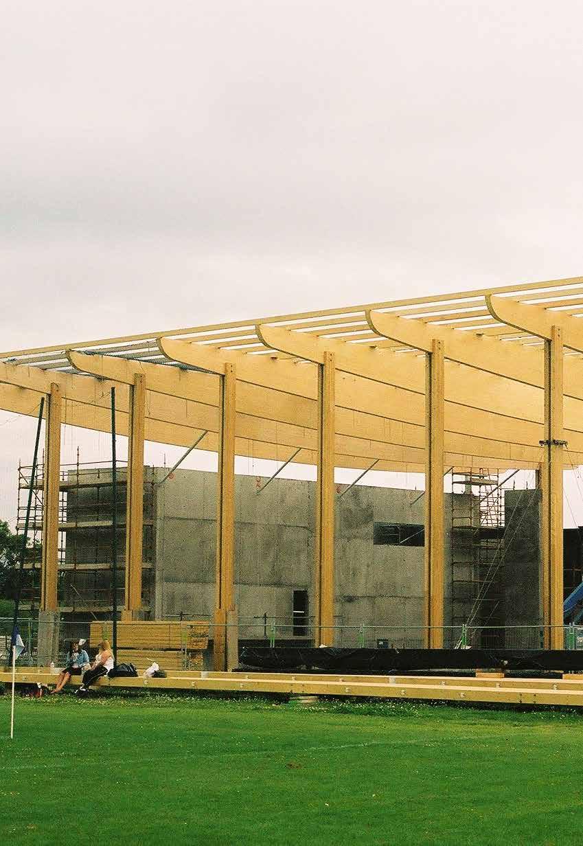
93
STRUCTURAL TIMBER DESIGN
 STRUCTURAL TIMBER DESIGN to Eurocode 5 2nd Edition Jack Porteous BSc, MSc, DIC, PhD, CEng, MIStructE, FICE Director lack Porteous Consultancy and Abdy Kernlani BSc, MSc, PhD, CEng, FIStructE, FIWSc Professor
European Technical Assessment ETA-17/1005 of
 ETA-Danmark A/S Göteborg Plads 1 DK-2150 Nordhavn Tel. +45 72 24 59 00 Fax +45 72 24 59 04 Internet www.etadanmark.dk Authorised and notified according to Article 29 of the Regulation (EU) No 305/2011
Verbindungselemente Engel GmbH Weltestraße Weingarten DEUTSCHLAND. Manufacturing plant 74437, , ,
 European Technical Assessment ETA-13/0536 of 20 February 2018 - Original version in German language General Part Technical Assessment Body issuing the European Technical Assessment: Trade name of the construction
nineteen Wood Construction 1 and design APPLIED ARCHITECTURAL STRUCTURES: DR. ANNE NICHOLS FALL 2016 lecture STRUCTURAL ANALYSIS AND SYSTEMS ARCH 631
 APPLIED ARCHITECTURAL STRUCTURES: STRUCTURAL ANALYSIS AND SYSTEMS DR. ANNE NICHOLS FALL 2016 lecture nineteen wood construction and design Wood Construction 1 Timber Construction all-wood framing systems
THE ENGINEERED WOOD ASSOCIATION
 D A T A F I L E APA Performance Rated Rim Boards A rim board is the wood component that fills the space between the sill plate and bottom plate of a wall or, in second floor construction, between the top
APA Performance Rated Rim Boards
 D a t a F i l e APA Performance Rated Rim Boards A Rim Board is the wood component that fills the space between the sill plate and bottom plate of a wall or, in second floor construction, between the top
European Technical Assessment ETA-13/0029 of 11/07/2017
 ETA-Danmark A/S Göteborg Plads 1 DK-2150 Nordhavn Tel. +45 72 24 59 00 Fax +45 72 24 59 04 Internet www.etadanmark.dk Authorised and notified according to Article 29 of the Regulation (EU) No 305/2011
Korean standards of visual grading and establishing allowable properties of softwood structural lumber
 Korean standards of visual grading and establishing allowable properties of softwood structural lumber Park, Moon-Jae 1, Shim, Kug-Bo 1 ABSTRACT Korean standards related to wood products such as "Sizes
ALONA YANSHINA EXERCISE 1.1
 material makeup: log ALONA YANSHINA EXERCISE 1.1 timeline + development log cabin - interlocked corners by cutting notches in the ends of the logs. using log joinery technique, structures grew higher logs
ADDENDUM (February 2014) 2012 NDS Changes John Buddy Showalter, P.E., Bradford K. Douglas, P.E., Philip Line, P.E., and Peter Mazikins, P.Eng.
 2012 NDS Changes John Buddy Showalter, P.E., Bradford K. Douglas, P.E., Philip Line, P.E., and Peter Mazikins, P.Eng.") ADDENDUM (February 2014) 2012 NDS Changes John Buddy Showalter, P.E., Bradford K. Douglas, P.E., Philip Line, P.E., and Peter Mazikins, P.Eng. 1) Add to section on Dowel-type Fasteners as follows: Section
ADDENDUM (February 2014) 2012 NDS Changes John Buddy Showalter, P.E., Bradford K. Douglas, P.E., Philip Line, P.E., and Peter Mazikins, P.Eng. 1) Add to section on Dowel-type Fasteners as follows: Section
VERSA-LAM. An Introduction to VERSA-LAM Products
 44 VERSA-LAM An Introduction to VERSA-LAM Products VERSA-LAM is one of the strongest and stiffest engineered wood products approved in the UK. 241 302 356 406 VERSA-LAM products are excellent as floor
European Technical Approval ETA-07/0212
 ETA-Danmark A/S Kollegievej 6 DK-2920 Charlottenlund Tel. +45 45 76 20 20 Fax +45 45 76 33 20 Internet www.etadanmark.dk Authorised and notified according to Article 10 of the Council Directive 89/106/EEC
T Wooden Structures 1
 T512903 Wooden Structures 1 Load Bearing Wooden Structures Structure of Wood Structural Properties of Wood Timber Glued Laminated Timber Laminated Veneer Lumber 1 T512903 Wooden Structures 1 Load Bearing
Wood. Wood construction
 CEEN 3144 Construction Materials Wood Francisco Aguíñiga Assistant Professor Civil Engineering Program Texas A&M University Kingsville Page 1 Wood construction Page 2 1 Wood construction Page 3 Advantages
Dowel-type fasteners. Timber Connections. Academic resources. Introduction. Deferent types of dowel-type fasteners. Version 1
 Academic resources Timber Connections Dowel-type fasteners Version 1 This unit covers the following topics: Deferent types of dowel-type fasteners Introduction There are four criteria designers should
Nailed Structural-Use Panel and Lumber Beams
 D A T A F I L E Nailed Structural-Use Panel and Lumber Beams When roof load or span requirements are too great to allow use of commonly available dimension lumber or timbers, a box beam constructed of
STRUCTURAL FINGER JOINTED SOLID TIMBER
 STRUCTURAL FINGER JOINTED SOLID TIMBER THE BEAM WITH THE CHARACTER OF SOLID TIMBER. 01 AT A GLANCE AREAS OF APPLICATION Single and multiple family houses Multi-storey residential buildings Industrial and
Glulam Connection Details
 T E C H N I C A L N O T E Glulam Connection Details Note: This version is superseded by a more current edition. Check the current edition for updated design and application recommendations. ENGINEERED
Wood Products Taxonomy
 THEN NOW Wood Products Taxonomy WOOD Composites Solid Wood Panels Engineered Lumber Composites (ELC) Softwood Lumber Glued Treated Hardwood Lumber Wood/ Non-wood Wood Based LVL Boards Finger joined CCA
European Technical Assessment. ETA-15/0667 of Member of. General part
 INSTITU Schenkenstrasse 4 T +43 1 533 65 50 1010 Vienna Ι Austria F +43 1 533 64 23 www.oib.or.at Ι mail@oib.or.at Designated according to Article 29 of Regulation (EU) No 305/2011 Member of www.eota.eu
2002 ADDENDUM to the 1997 NDS and PRIOR EDITIONS
 AMERICAN FOREST & PAPER ASSOCIATION American Wood Council Engineered and Traditional Wood Products March 2002 2002 ADDENDUM to the 1997 NDS and PRIOR EDITIONS The 2001 Edition of the National Design Specification
European Technical Assessment ETA-12/0197 of 12/07/2017
 ETA-Danmark A/S Göteborg Plads 1 DK-2150 Nordhavn Tel. +45 72 24 59 00 Fax +45 72 24 59 04 Internet www.etadanmark.dk Authorised and notified according to Article 29 of the Regulation (EU) No 305/2011
LVL8 H1.2 GENERAL FRAMING. Eco Friendly Revolutionary H1.2 Treatment Azotek by Zelam
 LVL8 H1.2 GENERAL FRAMING Eco Friendly Revolutionary H1.2 Treatment Azotek by Zelam NPIL/MARCH2015 Introduction to NelsonPine LVL8 H1.2 NelsonPine LVL is an engineered wood composite made from rotary peeled
European Technical Assessment. ETA-16/0902 of 17 March English translation prepared by DIBt - Original version in German language.
 European Technical Assessment ETA-16/0902 of 17 March 2017 - Original version in German language General Part Technical Assessment Body issuing the European Technical Assessment: Trade name of the construction
A Shell construction
 A Shell construction A 4/2012 Content 1 BASE AND WALL ANCHORING 1.1 Base with mortar bed 1.2 Base with sill plate 1.3 Base with raised sill plate 1.4 Concrete base (mortar bed) 1.5 Concrete base (sill
Timber fasteners for structural use
 TECHNICAL INFORMATION TIMBER FASTENERS FOR STRUCTURAL USE TESTING AND CERTIFICATION TI-17 V1 Timber fasteners for structural use Testing and certification 01 INTRODUCTION Timber fasteners for structural
Österreichisches Institut für Bautechnik Schenkenstrasse Vienna Austria T F
 Authorised and notified according to Article 10 of the Council Directive 89/106/EEC of 21 December 1988 on the approximation of laws, regulations and administrative provisions of Member States relating
MAT105: Floor Framing
 MAT105: Copyright 2007 American Forest & Paper Association, Inc. Because the common applications for wood framing are in residential construction, the details of this program will be based on the IRC which
Moment-Resisting Connections In Laminated Veneer Lumber (LVL) Frames
 Frames") Moment-Resisting Connections In Laminated Veneer Lumber (LVL) Frames Andy van Houtte Product Engineer-LVL Nelson Pine Industries Nelson, NZ Andy Buchanan Professor of Civil Engineering Peter Moss Associate
Moment-Resisting Connections In Laminated Veneer Lumber (LVL) Frames Andy van Houtte Product Engineer-LVL Nelson Pine Industries Nelson, NZ Andy Buchanan Professor of Civil Engineering Peter Moss Associate
Timber Rivet Connections Design Process for a Hanger Connection
 Timber Rivet Connections Design Process for a Hanger Connection RobertJ.Taylor,PhD,P.Eng.,Assoc.AIAand DavidM.Moses,PhD,P.Eng.,P.E.,LEED AP Introduction Timber rivet connections have been used successfully
National Design Specification for Wood Construction. Copyright Materials. Learning Objectives
 National Design Specification for Wood Construction The Wood Products Council is a Registered Provider with. Credit(s) earned on completion of this program will be reported to AIA/CES for AIA members.
ESR-1254 * DELETED BY CITY OF LOS ANGELES. Reissued April 1, 2006 This report is subject to re-examination in one year.
 ESR-1254 Reissued April 1, 2006 This report is subject to re-examination in one year. www.icc-es.org Business/Regional Office 5360 Workman Mill Road, Whittier, California 90601 (562) 699-0543 Regional
ESR-2403 Reissued October 1, 2009 This report is subject to re-examination in one year.
 ICC-ES Evaluation Report ESR-403 Reissued October, 009 This report is subject to re-examination in one year. www.icc-es.org (800) 43-6587 (56) 699-0543 A Subsidiary of the International Code Council DIVISION:
BRACING BRACING SECTION 7 SECTION 7
 If we are to learn from the past, it is clear that there is generally a lack of understanding of the purpose of roof bracing and who should be responsible for it. This has led to disputes, claims and,
European Technical Assessment ETA-04/0038 English translation prepared by DIBt. Page 2 of July 2016
 European Technical Assessment ETA-04/0038 Page 2 of 15 29 July 2016 The European Technical Assessment is issued by the Technical Assessment Body in its official language. Translations of this European
Regarding the code-compliance of CCA treated laminated veneer lumber
 Determination 2015/079 Regarding the code-compliance of CCA treated laminated veneer lumber Summary This determination discusses the pathway to establishing compliance with Clause B2.3.1 for laminated
Wood Products Taxonomy
 Then 1 Now 2 Wood Products Taxonomy WOOD Composites Solid Wood Panels Engineered Lumber Composites (ELC) Softwood Lumber Glued Treated Hardwood Lumber Wood/ Non-wood Wood Based LVL Boards Finger joined
Section Downloads. Lumber Design Values. Lumber Standard. Western Lumber Product Use Manual. Section 05: Truss Materials.
 Section Downloads Download & Print TTT I Sec 05 Slides TTT I Sec 05 Problem Handout TTT I Sec 05 Design Values Section 05: Truss Materials 1 PS 20-2010 Non-Printable Downloads Version 2.1 2 Lumber Design
European Technical Approval ETA-08/0165
 ETA-Danmark A/S Kollegievej 6 DK-2920 Charlottenlund Tel. +45 72 24 59 00 Fax +45 72 24 59 04 Internet www.etadanmark.dk Authorised and notified according to Article 10 of the Council Directive 89/106/EEC
SPECIFIC ENGINEERING DESIGN GUIDE
 SPECIFIC ENGINEERING DESIGN GUIDE LIMIT STATE DESIGN CHARACTERISTIC PROPERTIES AND STRUCTURAL DESIGN INFORMATION NPIL/03/DECEMBER2016 Introduction to NelsonPine LVL NelsonPine LVL is an engineered wood
European Technical Approval ETA-10/0038
 ETA-Danmark A/S Kollegievej 6 DK-2920 Charlottenlund Tel. +45 72 24 59 00 Fax +45 72 24 59 04 Internet www.etadanmark.dk Authorised and notified according to Article 10 of the Council Directive 89/106/EEC
Joint Evaluation Report
 0 Joint Evaluation Report ICC-ES (800) 423-6587 (562) 699-0543 www.icc-es.org 000 ESR-2909 Reissued 09/2017 This report is subject to renewal 09/2019. DIVISION: 06 00 00 WOOD, PLASTICS AND COMPOSITES SECTION:
Course Syllabus ARCHITECTURE 544 WOOD FRAMING. Organization. Evaluation. Text
 ARCHITECTURE 544 WOOD FRAMING Prof. Dr. Ing. Peter von Buelow pvbuelow@umich.edu 1205c Art & Architecture Bldg. Lecture Topics : Course Structure Codes NDS Approach Sawn Lumber Engineering Properties Engineered
REISSER-Schraubentechnik GmbH Fritz-Müller-Straße Ingelfingen-Criesbach DEUTSCHLAND
 European Technical Assessment ETA-11/0106 of 20 June 2016 - Original version in German language General Part Technical Assessment Body issuing the European Technical Assessment: Trade name of the construction
European Technical Assessment ETA-11/0024 of 08/07/2016
 ETA-Danmark A/S Göteborg Plads 1 DK-2150 Nordhavn Tel. +45 72 24 59 00 Fax +45 72 24 59 04 Internet www.etadanmark.dk Authorised and notified according to Article 29 of the Regulation (EU) No 305/2011
Sections & Details VOCABULARY
 1 Sections & Details VOCABULARY 1 ROOF FRAMING DETAIL RIDGE BOARD SHEATHING SHINGLES WEB FASCIA RAFTER (chord) SOFFIT SHEATHING STUD INSULATION DOUBLE TOP PLATE CEILING JOIST 2 FOUNDATION DETAIL STUD SHEATHING
LP SolidStart LSL. LP SolidStart LSL Prescriptive Roof Framing Technical Guide 2500F b-1.75e, 2360F b -1.55E and 1730F b -1.
 LP SolidStart LSL LP SolidStart LSL Prescriptive Roof Framing Technical Guide 2500F b-1.75e, 2360F b -1.55E and 1730F b -1.35E LSL Please verify availability with the LP SolidStart Engineered Wood Products
European Technical Assessment ETA-11/0024 of 02/03/2017
 ETA-Danmark A/S Göteborg Plads 1 DK-2150 Nordhavn Tel. +45 72 24 59 00 Fax +45 72 24 59 04 Internet www.etadanmark.dk Authorised and notified according to Article 29 of the Regulation (EU) No 305/2011
Eurocode EN Eurocode 3: 3 Design of steel structures. Part 1-1: General rules and rules for buildings
 Eurocode EN 1993-1-1 Eurocode 3: 3 Design of steel structures Part 1-1: General rules and rules for buildings Eurocode EN 1993-1-1 Eurocode 3 applies to the design of buildings and civil engineering works
Connection Philosophy. p NDS Chapter-by-chapter description Changes from previous editions Examples. Part 1: Member Design Webinar.
 Outline ASD and LRFD with the 2005 NDS Part 2 Connection Design Presented by: John Buddy Showalter, P.E. Vice President, Technology Transfer Connection philosophy p NDS Chapter-by-chapter description Changes
Pull-compression tests on glued-in metric thread rods parallel to grain in different timber species and laminated veneer lumber
 COST FP1004 15-17 April 2015 Lisbon, Portugal Pull-compression tests on glued-in metric thread rods parallel to grain in different timber species and laminated veneer lumber Frank Hunger 1, Mislav Stepinac
TECHNICAL MANUAL. TERADOWEL and ULTRADOWEL. Reliable Dowel System for Floor Joints
 TECHNICAL MANUAL TERADOWEL and ULTRADOWEL Reliable Dowel System for Floor Joints Version: PEIKKO GROUP 11/2018 TERADOWEL and ULTRADOWEL Reliable Dowel System for Floor Joints Dowels manufactured from high
Connection Design Examples
 Connection Design Examples Using the 2015 NDS (DES345) Lori Koch, P.E. Manager, Educational Outreach American Wood Council Adam Robertson, M.A.Sc., P.Eng. Manager, Codes and Standards Canadian Wood Council
European Technical Assessment ETA 15/0029 of 12/06/2017
 RISE Research Institutes of Sweden AB RISE Certifiering Box 553 SE-371 23 Karlskrona Sweden Member of www.eota.eu Tel: +46 10 516 63 00 Web: www.ri.se Mail: certifiering@ri.se European of 12/06/2017 General
European Technical Approval ETA-08/0183
 ETA-Danmark A/S Kollegievej 6 DK-2920 Charlottenlund Tel. +45 72 24 59 00 Fax +45 72 24 59 04 Internet www.etadanmark.dk Authorised and notified according to Article 10 of the Council Directive 89/106/EEC
Changes in the 2001 NDS for Wood Construction
 Changes in the 2001 NDS for Wood Construction Philip Line, P.E.; Dr. Robert Taylor, P.Eng.; John Buddy Showalter, P.E.; Bradford K. Douglas, P.E. Introduction The 2001 Edition of the National Design Specification
Statement for nail plate LL13 Combi
 STATEMENT NO VTT-S-0369-17 1 (5) Request by Order Contact person Ristek Oy Askonkatu 11 FI-15110 Lahti 15.3.017 Kimmo Köntti VTT Expert Services Ltd Ari Kevarinmäki P.O. Box 1001, FI-0044 VTT Tel. +358
ESR-2648 Reissued May 1, 2012 This report is subject to renewal June 1, 2013.
 ICC-ES Evaluation Report ESR-2648 Reissued May 1, 2012 This report is subject to renewal June 1, 2013. www.icc-es.org (800) 423-6587 (562) 699-0543 A Subsidiary of the International Code Council DIVISION:
Design Nailed and Wood Screwed Connections with Spreadsheet. Course Content
 Design Nailed and Wood Screwed Connections with Spreadsheet Course Content INTRODUCTION The complete design of a wood structure includes the design of connections between the various structural members.
AMTS STANDARD WORKSHOP PRACTICE. Bond Design
 AMTS STANDARD WORKSHOP PRACTICE Reference Number: AMTS_SWP_0027_2008 Date: December 2008 Version: A 1 Contents 1 Technical Terms...3 2 Scope...3 3 Primary References...3 4 Basic...3 4.1 Typical joint types...4
American Institute of Timber Construction 7012 South Revere Parkway Suite 140 Centennial, CO Phone: 303/ Fax: 303/
 American Institute of Timber Construction 7012 South Revere Parkway Suite 140 Centennial, CO 80112 Phone: 303/792-9559 Fax: 303/792-0669 404.1. SCOPE STANDARD FOR RADIALLY REINFORCING CURVED GLUED LAMINATED
AQA GCSE Design and Technology 8552
 AQA GCSE Design and Technology 8552 Natural and manufactured timbers Unit 3 Materials and their working properties 2 Objectives Know the primary sources of materials for producing natural and manufactured
Connections in CLT Assemblies
 Creating forest sector solutions www.fpinnovations.ca Connections in CLT Assemblies Cross Laminated Timber Symposium Vancouver, BC February 8-9, 2011 M. Mohammad Building Systems Wood Products Division
Tension Perpendicular to Grain Strength of Wood, Laminated Veneer Lumber, and a Wood Plastic Composite.
 Tension Perpendicular to Grain Strength of Wood, Laminated Veneer Lumber, and a Wood Plastic Composite. Tracy Hummer, Research Assistant J. Daniel Dolan, Professor Michael Wolcott, Professor Wood Materials
European Technical Approval ETA-08/0007
 ETA-Danmark A/S Kollegievej 6 DK-2920 Charlottenlund Tel. +45 72 24 59 00 Fax +45 72 24 59 04 Internet www.etadanmark.dk Authorised and notified according to Article 10 of the Council Directive 89/106/EEC
Featuring TJ Rim Board and TimberStrand LSL
 #TJ-8000 SPECIFIER S GUIDE TRUS JOIST RIM BOARD Featuring TJ Rim Board and TimberStrand LSL Multiple thicknesses, grades, and products to cover all your rim board needs 1¼" Thickness matches lateral load
LP SolidStart Laminated Strand Lumber (LSL) and Laminated Veneer Lumber (LVL) Louisiana-Pacific Corporation Revised July 21, 2017
 and Laminated Veneer Lumber (LVL) Louisiana-Pacific Corporation Revised July 21, 2017") LP SolidStart Laminated Strand Lumber (LSL) and Laminated Veneer Lumber (LVL) PR-L280(C) Louisiana-Pacific Corporation Revised July 21, 2017 Products: LP SolidStart 1.35E, 1.55E, and 1.75E LSL LP SolidStart
LP SolidStart Laminated Strand Lumber (LSL) and Laminated Veneer Lumber (LVL) PR-L280(C) Louisiana-Pacific Corporation Revised July 21, 2017 Products: LP SolidStart 1.35E, 1.55E, and 1.75E LSL LP SolidStart
European Technical Approval ETA-10/0413
 ETA-Danmark A/S Kollegievej 6 DK-2920 Charlottenlund Tel. +45 72 24 59 00 Fax +45 72 24 59 04 Internet www.etadanmark.dk Authorised and notified according to Article 10 of the Council Directive 89/106/EEC
Co-ordination of the Group of Notified Bodies for the Construction Products Directive 89/106/EEC. GNB-CPD Conference on CPR
 GNB-CPD All Co-ordination of the Group of Notified Bodies for the Construction Products Directive 89/106/EEC NB-CPD/All-13/112 Issued: 13 June 2013 Answers to GNB- CPD questions GNB-CPD Conference on CPR
AS/NZS :2012. Specification for preservative treatment AS/NZS :2012. Part 4: Laminated veneer lumber (LVL) Australian/New Zealand Standard
 Australian/New Zealand Standard") AS/NZS 1604.4:2012 Incorporating Amendment No. 1 Australian/New Zealand Standard Specification for preservative treatment Part 4: Laminated veneer lumber (LVL) Superseding AS/NZS 1604.4:2010 AS/NZS 1604.4:2012
AS/NZS 1604.4:2012 Incorporating Amendment No. 1 Australian/New Zealand Standard Specification for preservative treatment Part 4: Laminated veneer lumber (LVL) Superseding AS/NZS 1604.4:2010 AS/NZS 1604.4:2012
Ingenious hardwood. Ingenious hardwood. Order our BauBuche sample box free of charge. 1
 1 www.pollmeier.com +49 (0)36926 945-163 baubuche@pollmeier.com www.pollmeier.com Order our BauBuche sample box free of charge. Pollmeier Massivholz GmbH & Co.KG Pferdsdorfer Weg 6 99831 Creuzburg Errors
European Technical Assessment. ETA-14/0426 of 15 December English translation prepared by DIBt - Original version in German language
 European Technical Assessment ETA-14/0426 of 15 December 2014 - Original version in German language General Part Technical Assessment Body issuing the European Technical Assessment: Trade name of the construction
European Technical Assessment. ETA-12/0373 of Member of. General part
 INSTITU Schenkenstrasse 4 T +43 1 533 65 50 1010 Vienna Ι Austria F +43 1 533 64 23 www.oib.or.at Ι mail@oib.or.at Designated according to Article 29 of Regulation (EU) No 305/2011 Member of www.eota.eu
PART II ENGINEERED BASIS OF RIDGE AND EAVE VENT DETAILS
 PART II ENGINEERED BASIS OF RIDGE AND EAVE VENT DETAILS A - INTRODUCTION This report addresses engineered design for unblocked wood structural panel (plywood or OSB) roof diaphragms with either continuous
European Technical Approval ETA-13/0630
 ETA-Danmark A/S Kollegievej 6 DK-2920 Charlottenlund Tel. +45 72 24 59 00 Fax +45 72 24 59 04 Internet www.etadanmark.dk Authorised and notified according to Article 10 of the Council Directive 89/106/EEC
European Technical Approval ETA-12/0114
 ETA-Danmark A/S Kollegievej 6 DK-2920 Charlottenlund Tel. +45 72 24 59 00 Fax +45 72 24 59 04 Internet www.etadanmark.dk Authorised and notified according to Article 10 of the Council Directive 89/106/EEC
Bolt Material Types and Grades 1- Bolts made of carbon steel and alloy steel: 4.6, 4.8, 5.6, 5.8, 6.8, 8.8, 10.9 Nuts made of carbon steel and alloy
 Bolt Material Types and Grades 1- Bolts made of carbon steel and alloy steel: 4.6, 4.8, 5.6, 5.8, 6.8, 8.8, 10.9 Nuts made of carbon steel and alloy steel: 4, 5, 6, 8, 10, 12 2- Bolts made of stainless
5/16/2017. Timber Design
 Timber Design Wood is a very versatile raw material and is still widely used in construction, especially in countries such as Canada, Sweden, Finland, Norway and Poland, where there is an abundance of
WOODEN BUILDINGS 6.1 INTRODUCTION 6.2 TYPICAL DAMAGE AND FAILURE OF WOODEN BUILDINGS. Chapter 6
 Chapter 6 WOODEN BUILDINGS 6.1 INTRODUCTION Wood has higher strength per unit weight and is, therefore, very suitable for earthquake resistant construction. But heavy cladding walls could impose high lateral
European Technical Assessment. ETA-12/0056 of General Part. Technical Assessment Body issuing the ETA:
 Member of SINTEF Building and Infrastructure P.O.Box 124 Blindern NO-0314 Oslo, Norway Phone +47 40 00 51 00 e-mail: certification@sintef.no www.eota.eu European Technical Assessment ETA-12/0056 of 2018-12-15
BauBuche Fasteners and connections
 BauBuche Fasteners and connections Beech laminated veneer lumber Chapter under revision 05 BauBuche Fasteners and connections 05 04-18 - EN Sheet 1 / 10 Fasteners and connections Sheet CONTENTS 2 3 4 9
Sections & Details. WOOD SILL and FLOOR CONSTRUCTION NOTES
 2 Sections & Details WOOD SILL and FLOOR CONSTRUCTION NOTES 1 Commonly Used Lumber Common LENGTHS include: 8, 10, 12, 14, 16 NOMINAL SIZES 2 x 4 2 x 6 2 x 8 2 x 10 2 x 12 ACTUAL SIZES 1 ½ x 3 ½ 1 ½ x 5
Unit 2 Engineered Panels
 Unit 2 Engineered Panels MULTICHOICE 1. What is another name for large, reconstituted wood sheets or panels? (A) formed panels (B) engineered panels (C) architectural panels (D) construction panels 2.
Glulam Curved Members. Glulam Design. General Glulam Design. General Glulam Beams are Designed in the SAME Manner as Solid Sawn Beams
 Glulam Curved Members Glulam Design General Glulam Beams are Designed in the SAME Manner as Solid Sawn Beams There is an Additional Adjustment Factor, C v, the Volume Factor C v and C L (Lateral Stability
5. Timber Application, Products and their use
 TIMBER 5. Timber Application, Products and their use Lecturer: Prof. Dr. Mohammad Ismail Faculty of Civil Engineering, -Skudai, Johor Darul Ta zim, MALAYSIA 1 Room : C09-313 Tel : 07-5531688 December 6,
Beam & Header Technical Guide. LP SolidStart LVL. 2900F b -2.0E. U.S. Technical Guide U.S. TECHNICAL GUIDE
 U.S. Technical Guide U.S. TECHNICAL GUIDE LP SolidStart LVL & Header Technical Guide 2900F b -2.0E Please verify availability with the LP SolidStart Engineered Wood Products distributor in your area prior
Regarding the durability of New Zealand grown European oak timber to be used internally in a new dwelling at 350 Jones Road, Blenheim
 Determination 2016/025 Regarding the durability of New Zealand grown European oak timber to be used internally in a new dwelling at 350 Jones Road, Blenheim Summary This determination discusses the compliance
GLUED SOLID TIMBER DUO/TRIO
 GLUED SOLID TIMBER DUO/TRIO THE DIMENSIONALLY STABLE AESTHETE. 01 AT A GLANCE AREAS OF APPLICATION Single and multiple family houses Multi-storey residential buildings Visual application with the highest
ICC-ES Evaluation Report Reissued March 1, 2011 This report is subject to renewal in two years.
 ICC-ES Evaluation Report www.icc-es.org (800) -6587 (56) 699-05 ESR-0 Reissued March, 0 This report is subject to renewal in two years. A Subsidiary of the International Code Council DIVISION: 06 00 00
ROOF-CEILING CONSTRUCTION
 CHAPTER 8 ROOF-CEILING CONSTRUCTION SECTION R801 GENERAL R801.1 Application. The provisions of this chapter shall control the design and construction of the roof-ceiling system for all buildings. R801.2
European Technical Approval ETA-11/0283
 European Technical Approval ETA-11/0283 - Original version in German language Handelsbezeichnung Trade name Zulassungsinhaber Holder of approval Zulassungsgegenstand und Verwendungszweck Generic type and
Licensed Copy: RRICTISQ RRICTISQ, ISO/Exchange Russia, 01 December 2004, Uncontrolled Copy, (c) BSI
 BSI") BRITISH STANDARD BS EN 392:1995 Glued laminated timber Shear testof glue lines The European Standard EN 392:1995 has the status of a British Standard BSEN 392:1995 Committees responsible for this British
BRITISH STANDARD BS EN 392:1995 Glued laminated timber Shear testof glue lines The European Standard EN 392:1995 has the status of a British Standard BSEN 392:1995 Committees responsible for this British
Collins Engineers Palmetto Islands County Park Boardwalk Repairs 03/28/2014 SECTION ROUGH CARPENTRY
 PART 1 GENERAL 1.1 RELATED SECTIONS SECTION 061000 ROUGH CARPENTRY A. Drawings and general provisions of the Construction Contract, including General Conditions and Division 1 Specification Sections, apply
PRACTICE NOTE NO: 13 Version 1 Amended March 2001 Page 1 of 6 PRECAST CONCRETE ELEMENT DESIGN RESPONSIBILITIES AND CONTRACTUAL ARRANGEMENTS
 PRACTICE NOTE NO: 13 Version 1 Amended March 2001 Page 1 of 6 Scope This Practice Note is intended to identify responsibilities and contractual arrangements for precast elements used in buildings. Such
Nordic wood preservation classes and product requirements for preservative-treated wood
 Nordic wood preservation classes and product requirements for preservative-treated wood NWPC Document No 1:2011 Nordic Wood Preservation Council 2011 NWPC Document No 1: 2011 Nordic wood preservation classes
The Influence of Nails and Plasterboard on the Racking Resistance of Stud Walls
 Building 1 Grosvenor Court, Hipley Street OLD WOKING, SURREY GU22 9LL Tel: +44 (0) 1483 769518 Fax: +44 (0) 1483 770863 E-mail: design@silvatecdesigncom Internet: wwwsilvatecdesigncom The Influence of
Expressed Hardwood Structures
 Expressed Hardwood Structures Introduction This guide provides ideas and design information to assist in the development of expressed native timber structures in buildings. Basic information on how to
ARCH Structures 2, Winter 2009
 University of Michigan Deep Blue deepblue.lib.umich.edu 2009-01 ARCH 324 - Structures 2, Winter 2009 von Buelow, Peter Buelow, P. v. (2008, December 19). Structures 2. Retrieved from Open.Michigan - Educational
ISO INTERNATIONAL STANDARD. Non-destructive testing of welds Radiographic testing of fusionwelded
 INTERNATIONAL STANDARD ISO 17636 First edition 2003-09-15 Non-destructive testing of welds Radiographic testing of fusionwelded joints Contrôle non destructif des assemblages soudés Contrôle par radiographie
SIMPLIFIED DESIGN PROCEDURE FOR GLUED-LAMINATED BRIDGE DECKS
 ABSTRACT Procedures have recently been developed for the design of glued-laminated bridge decks and for steel dowel connectors. However, since most bridges are designed in accordance with the Specifications