RIDGE MAST MOUNT (RMM)
|
|
|
- Emerald Hunter
- 5 years ago
- Views:
Transcription
1 May 5, 009 Revision E ASSEMBLY MANUAL (RMM) General Dynamics Satcom Technologies 1500 PRODELIN DRIVE NEWTON NC
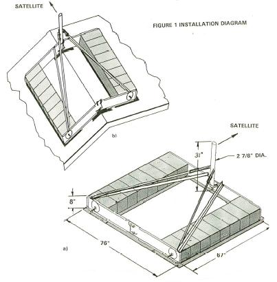
2 1.0 INTRODUCTION: 1.1 Features: The Ridge Mast Mount (RMM) is designed for use as a non penetrating mast mount for the.75m, 1.0M and 1.M General Dynamics Antenna. It has several unique features as given below: 1. It can be used on flat roofs (with up to 5 degree slopes) as well as peaked roofs up to a 30 degree pitch as shown in Figure 1.. The ballast is fixed and held captive by the tension rods and is integral to the mount structure. 3. The design incorporates Belville washers stamped into the end plates that allow for the expansion and contraction of the blocks during thermal changes while still maintaining a rigid structure. 4. As shown in Tables 1,, and 3, with smaller antennas, higher wind speeds, exposure factor, height above ground can be tolerated. The smaller antenna presents less area and hence has less wind force than a larger antenna. 5. Note that this mount can also be used on flat roofs and therefore substitute for the 5 1/ x 5 1/ NPMM. 6. The mount will require the use of a tether (especially when used on a peaked roof or where a sliding mount could leave the roof). Those installations where a natural barrier exist, like a parapet, will not require the tether. Initially this tether will have to be locally purchased and fabricated from 3/16 steel cable and attached to the mast and tether point with three (3) cable clamps on each end. 7. Note that the diagonal braces can be temporarily used in the peaked roof application to help hold the concrete blocks in place until they can be skewered by the rods. 8. The mount is light and compact and can be easily and economically shipped. 9. Because the mount requires 16 concrete blocks the installer cannot put too few ballast blocks on the mount.
3 10. Because the ballast is held captive, it is more difficult to later remove the blocks for some other purpose and hence risk the mount moving. 11. The rubber pads are provided to protect the roof as well as to provide a uniform coefficient of friction to prevent sliding. The pad is made of Butyl rubber and is designed to be compatible with most roof surfaces (asphalt, tile, membrane, tar and etc.) and to be resistant to deterioration due to weather (e.g. rain, snow and ice),most chemicals and ultra-violet light from the sun. It is not known to react with or be harmful to any roof material. 1. TOOLS REQUIRED: TOOL REQUIRED 7/16" SOCKET or WRENCH 9/16" SOCKET and WRENCH 3/4" WRENCH ( REQUIRED) HARDWARE SIZE USED ON 1/4-0 3/8-16 1/-13 MAXIMUM RECOMMENDED TORQUE (ft/lbs) 6 19 ADDITIONAL TOOLS REQUIRED: 1 Rake or Shovel (to remove rocks) 1 Broom (to sweep away dirt and small rocks) 1.3 SHIPPING / INSTALLED SIZE AND WEIGHT Shipping Size and Weight Installed Size and Weight Total Weight of Various Antennas 8 x 3 x 7 Box Mount (less pads) 70 lbs 0.75M 1.0M 1.M 97 pounds Concrete blocks (16 x 30 lbs) 480 lbs Total Mount 550 lbs Antenna Outdoor Unit(ODU) Ridge Mast Mount Total Installed Wt
4 4
5 .0 APPLICATION INSTRUCTIONS (1) Locate your installation site on the Wind Speed Map ( ) from Figure. () Determine the design wind speed from the map for your location. (3) Select the proper exposure factor (B or C) as described below. Exposure B: Urban and suburban areas, wooded areas, or other terrain with numerous closely spaced obstructions having the size of single family dwellings or larger. Obstructions must extend 1500 feet in all directions from the building. Exposure C: Open terrain with widely scattered obstructions having heights generally less than 30 feet. Includes flat, open country and grass lands. (4) Using the design wind speed and the exposure factor, determine the maximum building height from the tables 1 for 0.75M, for 1.0M and 3 for 1.M. If the actual building is taller than the height given in the table, the RIDGED ROOF MOUNT cannot be installed at this site. (5) Maximum pitch of roof for use on peaked roof is 30 degrees. (6) If used on corrugated roof, fill in between corrugations with weather treated lumber. (7) The 8" x 8" x 16" concrete blocks must be manufactured in accordance e with ASTM C90, Grade N-1. The concrete blocks shall average at least 8 pound each. If not, add weight by breaking blocks into small pieces and inserting the pieces in the cavity of the blocks, (one block per side). The pieces will be captured at final assembly. 5
6 TABLES # METER RECTANGULAR ANTENNA PEAKED OR FLAT ROOFS DESIGN WIND SPEED (MPH) EXPOSURE B MAXIMUM BUILDING HEIGHT (Feet) EXPOSURE C MAXIMUM BUILDING HEIGHT (Feet) TABLE # METER RECTANGULAR ANTENNA PEAKED OR FLAT ROOFS DESIGN WIND SPEED (MPH) EXPOSURE B MAXIMUM BUILDING HEIGHT (Feet) EXPOSURE C MAXIMUM BUILDING HEIGHT (Feet) DESIGN WIND SPEED (MPH) TABLE #3-1. METER OFFSET ANTENNA PEAKED OR FLAT ROOFS EXPOSURE B MAXIMUM BUILDING HEIGHT (Feet) EXPOSURE C MAXIMUM BUILDING HEIGHT (Feet)

7 7
8 RIDGE AND FLAT ROOF MOUNT INSTALLATION INSTRUCTIONS Note: The Ridge and Flat Roof Mount can be installed on peak roofs or flat roofs. The following instructions have been generalized for either type of installation. (1) See Figure 7 and 8 and Table 4 for identification of the parts. () Select the installation area. Locate South and plan to direct the mount generally South. For peak roofs select the direction closest to direction of the satellite of interest. (see Figure 1 and 7 for the definition of mount direction). (3) Assemble an end plate with full flanges to an end plate with cut-off flanges using three (3) 3/8-16 x 1.0" long bolts, six (6) flat washers, 3 lock washers and nuts. Hand tighten only. NOTE: On peak roofs position end plates so the same amount of slot shows above the tops of the end plates. FIGURE 3 8
9 (4) Assemble the remaining two end plates using one (1) 3/8-16 x 1.0" bolt (in the bottom slot), the large U-Bolt, U-Bolt Saddle and notched angle (in the top slot and hole), (4) 3/8" flat washers, (3) lock washers and (3) hex nuts. Bend the notched angle as required. Hand tighten the bolt but leave the U-Bolt loose. NOTE: On peak roofs position end plates so the same amount of slot shows above the tops of the end plates. (Same as Figure 3) FIGURE 4 9
10 (5) Place rubber pads on roof using end plates to locate position. Flanges on end plates point out, away from mount. FIGURE 5 10

11 (6) Place 16 concrete blocks on rubber (8 each side). Note: If concrete blocks slide on roof, they can be temporarily held in place using angle braces as shown. FIGURE 6 11
12 (7) Skewer threaded rods through concrete blocks and plates. Fasten using flat washers and nuts (4 places). Fully tighten nuts. Then add a second nut and fully tighten. (see Figure 7). (8) Fully tighten the straight bolts that join the end plates. Do not tighten U-Bolt at this time. (4, 3/8-16 x 1.0" bolts). NOTE: Check to be sure the same amount of slot shows above the end plates as set in steps and 3. (9) Attach angle braces using 3/8-16 x 1.0" long bolts, nuts and flat washers. Finger tight only. (see Figure 7). Note the hardware captures the notched angle (from step 4). (10) Slide mast pipe down through U-Bolt until the bottom touches the lower bolt thru the end plates. (see Figure 7). (11) Attach tube supports to the angle braces using 3/8-16 x 1.0" bolts, nuts and flat washers. Finger tight only. (1) Attach channels to mast pipe using 3/8-16 x 4.0" bolt, nut, lock washer and flat washers. Finger tight only. NOTE: The head of the bolt must be on the opposite side of the pipe from the channel it is holding. (13) Fasten tube supports to the channels using two small U-Bolts and U-Bolt plate. Position first U-Bolt to within 1" of end of tube support. Finger tight only. (14) Fully tighten angle braces to the end plates. (4 places). (15) Fully tighten tube supports to the angle braces. ( places). (16) Fully tighten channels to the mast pipe. ( places). (17) Level mast pipe and fully tighten small U-Bolts. (18) Fully tighten large U-Bolt. 1

13 FIGURE 7 13
14 FIGURE 8 14
15 TABLE #4 - PARTS LIST AND WEIGHT ITEM # PART # DESCRIPTION QTY L.H. END PLATE R.H. END PLATE MOUNTING PLATE BRACKET COMPRESSION ROD U-BOLT CHANNEL 3/8-16 x 3" U-BOLT END PLATE ANGLE DIAGONAL ANGLE BRACE CHANNEL BRACE CLAMP MAST PIPE DIAGONAL TUBE BRACE 1/16 x 18 x 70" RUBBER PAD 1/16 x 18 x 6" RUBBER PAD 3/8-16 x 4.00" BOLT 3/8-16 x.75" BOLT 1/4-0 HEX NUT 3/8-16 HEX NUT 1/-13 HEX NUT 1/4" FLAT WASHER 3/8" FLAT WASHER 1/" FLAT WASHER 1/4-0 x 1" U-BOLT 1/4" LOCK WASHER 3/8" LOCK WASHER
.84M Ku-Band Rx/O Antenna System
 4096-644 Revision A May 9, 2003 ASSEMBLY MANUAL.84M Ku-Band Rx/O Antenna System PRODELIN CORPORATION 1500 PRODELIN DRIVE NEWTON, NC 28658 .84M Ku-Band Rx/O Antenna System A ORIGINAL RELEASE 5/9/2003 A.Hahn
.98M Ku-BAND Rx/Tx ANTENNA SYSTEM
 Revision C January 2, 2002 ASSEMBLY MANUAL ANTENNA SYSTEM PRODELIN CORPORATION 1500 Prodelin Drive Newton NC 28658 ANTENNA SYSTEM C Revised Series text B Revised Address 1/2/02 RAH A Revise and Update
1.8 METER SERIES 1194 ANTENNA SYSTEM
 January 14, 2002 REVISION G ASSEMBLY MANUAL 1.8 METER SERIES 1194 ANTENNA SYSTEM PRODELIN CORPORATION 1500 Prodelin Drive Newton NC 28658 1.8 METER SERIES 1194 ANTENNA SYSTEM G Revise Address 1/14/02 F
1.2M Ku-BAND Rx/Tx SERIES 1134 ANTENNA SYSTEM
 August 21, 1997 Revision D ASSEMBLY MANUAL 1.2M Ku-BAND Rx/Tx SERIES 1134 ANTENNA SYSTEM PRODELIN CORPORATION 1700 NE CABLE DRIVE CONOVER, NC 28613-0368 1.2M Ku-BAND Rx/Tx SERIES 1134 ANTENNA SYSTEM D
1.8 METER SERIES 1184 ANTENNA SYSTEM
 REVISION F January 10, 2002 ASSEMBLY MANUAL 1.8 METER SERIES 1184 ANTENNA SYSTEM PRODELIN CORPORATION 1500 Prodelin Drive Newton NC 28658 1.8 METER SERIES 1184 ANTENNA SYSTEM F Revised Address 1/10/02
1.2M Ku-BAND Rx/Tx SERIES 1132 ANTENNA SYSTEM
 August12, 2003 ASSEMBLY MANUAL Revision E 1.2M Ku-BAND Rx/Tx SERIES 1132 ANTENNA SYSTEM PRODELIN CORPORATION 1500 Prodelin Drive Newton NC 28658 1.2M Ku-BAND Rx/Tx SERIES 1132 ANTENNA SYSTEM E Revised
STRATUS SHELTER. Take bike parking to new heights
 Take bike parking to new heights The Stratus Shelter is a striking bike shelter option for any transit station, university campus, or multi-family residential building project. It is constructed of American
MTS-SP100. RENOGY Pole Mount System E Philadelphia St, Ontario, CA Version: 1.2
 MTS-SP100 RENOGY Pole Mount System 2775 E Philadelphia St, Ontario, CA 91761 1-800-330-8678 1 Version: 1.2 Important Safety Instructions Please save these instructions. This manual contains important safety,
1 of 9 SITE PLAN modules at 325W kw. Sample GAMECHANGE SOLAR. Sample. Sample AERIAL VIEW. Array Information. Design Information.
 AERIAL VIEW Array Information PV Modules Racking Manufacturer Hyundai Gamechange Racking Model HiS-S325TI 5-Degree GC Grid-Lite Dimensions." x 39.29" x.9" Weight 5. lbs Quantity 224 224 modules at 325W
1.2 METER SERIES 1130 Rx/O ANTENNA SYSTEM
 REVISION H April 20, 2016 ASSEMBLY MANUAL 1.2 METER SERIES 1130 Rx/O ANTENNA SYSTEM General Dynamics SATCOM Technologies 1700 Cable Drive NE Conover NC 28613 USA Phone 770-689-2040 www.gdsatcom.com 1.2
INDEX PAGE RELEASE SECTION NUMBER DATE
 INSTALLATION INSTRUCTIONS For Wind Zone 1 (other Wind Zones available on request) Version 11/20/2002 INDEX PAGE RELEASE SECTION NUMBER DATE Approval INTRODUCTION 2 2/26/2001 GENERAL INSTALLATION 3 2/26/2001
INSTALLATION INSTRUCTIONS CONTOURED LIGHT BAR APPLICATION: CHEVY EQUINOX/ GMC TERRAIN PART NUMBERS: ,
 INSTALLATION INSTRUCTIONS CONTOURED LIGHT BAR APPLICATION: 2010-2014 CHEVY EQUINOX/ GMC TERRAIN PART NUMBERS: 32-21020, 32-21025 ITEM QUANTITY DESCRIPTION TOOLS NEEDED 1 1 CONTOUR BAR TORQUE WRENCH 2 1
INSTALLATION INSTRUCTIONS
 B E Fig. 1 A J INSTALLATION INSTRUCTIONS REESE Steadi-Flex K H 66557 250LB 400LB Weight Distributing Kits 66558 400LB 600LB G D C F A 1 BALL MOUNT B 1 DRAW BAR C 2 3/4-10 x 4-1/2" GR.8 HEX HEAD BOLT D
KOLO SHELTER Installation Instructions Parts List
 Parts List Roof Cap Rafter Upright Polycarbonate Polycarbonate Drop Polycarbonate Flange Center Weldment (Short length shown above) Polycarbonate Edge Bolt.25 x 6.5 Bolt.625 x 7.5 Threaded Rod.75 x 14
Installation Instructions Kit, Base Rail Bracket Part # 31413
 Installation Instructions Kit, Base Rail Bracket Part # 31413 Dealer / Installer: Provide a copy of these Instructions to the end user of this product. These Instructions provide important operating and
OWNERS MANUAL. Model No LB. POLY PRO SPIKER/SPREADER. CAUTION: Read Rules for Safe Operation and Instructions Carefully
 OWNERS MANUAL Model No. -0301 CAUTION: Read Rules for Safe Operation and Instructions Carefully 17 LB. POLY PRO SPIKER/SPREADER Safety Assembly Operation Maintenance Parts PRINTED IN U.S.A. FORM NO. 78
RBP-1215B-RX DODGE RAM QUAD CAB RX3
 RBP-1215B-RX3 2002-2017 DODGE RAM 15-3500 QUAD CAB RX3 Passenger side RX-3 Side Step Drill Template Passenger side rear Modular Bracket (6) L Support Brackets Driver side rear Modular Bracket Driver side
HANDLING AND ASSEMBLY INSTRUCTIONS FOR TRUE FOCUS 3.0M, 3.8M AND 4.2M ANTENNAS WITH POLAR MOUNT
 HANDLING AND ASSEMBLY INSTRUCTIONS FOR TRUE FOCUS 3.0M, 3.8M AND 4.2M ANTENNAS WITH POLAR MOUNT Introduction SECTION 1 Thank you for purchasing one of our fine True Focus products. This manual covers the
Toyota 4 Runner and Lexus GX Skid Plate installation instructions.
 Toyota 4 Runner and Lexus GX Skid Plate installation instructions. NOTE: When installing the full set of skid plate start at the rear of the vehicle and work your way forward. NOTE: Torque Specs: Tighten
Heavy Duty Ceiling Tilt Mount Installation Manual
 HD-CTM-5580 Heavy Duty Ceiling Tilt Mount Installation Manual *This Installation requires a minimum of two people. For your safety: Read the complete instruction manual before starting an installation
Modular Shelter Breezeway Assembly Instructions
 Modular Shelter Breezeway Assembly Instructions Hardware Kit 76900188 THANK YOU FOR PURCHASING THIS PRODUCT Behlen Country has been in the business of providing quality products for more than 75 years.
southpaw enterprises, inc.
 southpaw enterprises, inc. Store these instructions with the enclosed maintenance checklist in a safe place. You may also access them on our website. Instruction Sheet Wood Joist 2-1/2 Ft. Drop Ceiling
ShorePort PWC Lift Instructions " x 138" Sandstone ShorePort " x 138" White ShorePort " x 138" Tan ShorePort
 ShorePort PWC Lift Instructions 00-8" x 8" Sandstone ShorePort 009-8" x 8" White ShorePort 090-8" x 8" Tan ShorePort....... - PUT SAFETY FIRST To avoid the risk of personal injury or death, study and fully
SERIES M Ku-BAND Rx / Tx ANTENNA SYSTEM
 4096-432 June 15, 2011 REVISION D ASSEMBLY MANUAL SERIES 1125 1.2M Ku-BAND Rx / Tx ANTENNA SYSTEM General Dynamics 1500 PRODELIN DRIVE NEWTON, NC 28658 PRODELIN CORPORATION 4096-432 SERIES 1125 1.2M Ku-BAND
Size Grade Torque 9/ ft/lbs. 5/ ft/lbs. 3/ ft/lbs. 7/ ft/lbs ft/lbs.
 8-3 HJ3205,Rev 4 BOlT TORQUE SPECIfICATIONS STANDARD BOlTS: Size Grade Torque 5/6 5 20 ft/lbs. 3/8 5 35 ft/lbs. 7/6 5 56 ft/lbs. /2 5 85 ft/lbs. Size Grade Torque 9/6 5 23 ft/lbs. 5/8 5 70 ft/lbs. 3/4
4099T Parts List. Front Bow Assy. (1) Rear Bow Assy. (1) Long Mounting Rail (2) Short Mounting Rail (2)
 Rear Bow Assy. (1) Long Mounting Rail (2) Short Mounting Rail (2)") 4099T Parts List Ver.2 Front Bow Assy. (1) Rear Bow Assy. (1) Small Mnt Foot (2) Large Mount Foot (2) Ladder Hook (2) Ladder Stop (2) Handle Extension (1) Long Mounting Rail (2) Short Mounting Rail (2)
4099T Parts List Ver.2 Front Bow Assy. (1) Rear Bow Assy. (1) Small Mnt Foot (2) Large Mount Foot (2) Ladder Hook (2) Ladder Stop (2) Handle Extension (1) Long Mounting Rail (2) Short Mounting Rail (2)
ALUMINUM FOOTBALL GOALS INSTRUCTIONS WARNING WARNING Upright. Upright. Flag. Flag. Offset Pole.
 ALUMINUM FOOTBALL GOALS INSTRUCTIONS 800-67-090 Flag Flag Ground Sleeve Anchor Kit WARNING Football goals are shipped unassembled. Read all instructions thoroughly before attempting to assemble this equipment.
Multi-Stage ASSEMBLY INSTRUCTIONS ST-8100 SERIES. 125 TAYLOR PARKWAY ARCHBOLD, OH PHONE: (419) FAX: (419)
 FAX: (419)") 125 TAYLOR PARKWAY ARCHBOLD, OH 43502 PHONE: (419) 445-8915 FAX: (419) 445-0367 www.biljax.com Multi-Stage ST-8100 SERIES ASSEMBLY INSTRUCTIONS ALL DRAWINGS ARE FOR ILLUSTRATION ONLY. PRINTED IN U.S.A.
125 TAYLOR PARKWAY ARCHBOLD, OH 43502 PHONE: (419) 445-8915 FAX: (419) 445-0367 www.biljax.com Multi-Stage ST-8100 SERIES ASSEMBLY INSTRUCTIONS ALL DRAWINGS ARE FOR ILLUSTRATION ONLY. PRINTED IN U.S.A.
Instruction Guide 4A90L
 Instruction Guide 4A90L Kargo Master Rancho Cordova, CA 95742 800-343-7486 CustomerService@KargoMaster.com DATE: *PLEASE READ ALL INSTRUCTIONS AND WARNINGS PRIOR TO ASSEMBLING, INSTALLING, AND USING THIS
5/16" Flange nut. Bolt Keeper Plate (8" Sq. SYS.) (3) 1/2" x 3" Hex head connector zinc plated bolt w/ washers and nut. Anchor 3" sq. 7 Ga.
 (3) 1/2 x 3 Hex head connector zinc plated bolt w/ washers and nut. Anchor 3 sq. 7 Ga.") 2 1/2" x 2 1/2" x 10 Ga. 6" 5" 4" Variable Slipbase (8" Sq. SYS.) 5/16 Corner Bolt W/ nut 5/16" Flange nut Stub Insert (8" Sq. SYS.) Bolt Keeper Plate (8" Sq. SYS.) (3) 1/2" x 3" Hex head connector zinc
2 1/2" x 2 1/2" x 10 Ga. 6" 5" 4" Variable Slipbase (8" Sq. SYS.) 5/16 Corner Bolt W/ nut 5/16" Flange nut Stub Insert (8" Sq. SYS.) Bolt Keeper Plate (8" Sq. SYS.) (3) 1/2" x 3" Hex head connector zinc
F l a t S c r e e n A R M S I n s t a l l a t i o n
 ITEM NUMBERS (1) #TOACAORG16 (2) #TOACAORG20 (3) #TOACATRP24 (4) #TOACATRP30 (5) #TOACATRPDS (6) #TOACATRPSS TOOLS REQUIRED (1) 3/8 Wrench (not provided) (2) Phillips head screwdriver (not provided) (1)
LB. POLY PRO DROP SPREADER
 owners manual Model No. -02882 17 LB. POLY PRO DROP SPREADER CAUTION: Read Rules for Safe Operation and Instructions Carefully Safety Assembly Operation Maintenance Parts the fastest way to purchase parts
FRAME BRACKET. Doing Our Best to Provide You the Best. Ford. Page 1. BOlT TORQUE SPECIFICATIONS HJ31000,Rev 0
 2-13 HJ31000,Rev 0 Ford BOlT TORQUE SPECIFICATIONS METRIC BOlTS Size Grade Torque 8mm 8.8 23 ft/lbs. 10mm 8.8 45 ft/lbs. 12mm 8.8 78 ft/lbs. 14mm 8.8 125 ft/lbs. STANDARD BOlTS Size Grade Torque 5/16 5
INSTALLATION INSTRUCTIONS FOR FRONT CASTING DECK RAIL Ranger
 INSTALLATION INSTRUCTIONS FOR FRONT CASTING DECK RAIL Ranger TOOLS REQUIRED FOR INSTALLATION: Drill motor, (1) 5/16 inch drill bit, (1) 13/64 drill bit, (1) 3/16 inch hex wrench (1) 3/32 inch hex wrench.
400A 40113V, 401A 40120V, & 401AL 40120VL ALUMINUM VERTICAL 4000 LB LIFT INCLUDES SCREW LEG ASSEMBLY INSTRUCTIONS
 12/11/07 PAGE 1 OF 12 400A 40113V, 401A 40120V, & 401AL 40120VL ALUMINUM VERTICAL 4000 LB LIFT INCLUDES SCREW LEG ASSEMBLY INSTRUCTIONS Thank you for purchasing our product! *Please read these instructions
STEP 1 STEP 2 LEVELER KIT OPTION MOBILE CASTER KIT OPTION
 B SERIES INDUSTRIAL BENCHES TOOLS REQUIRED FOR ASSEMBLY Socket set, Open end wrench set, Cordless drill with 3/8" socket bit (Magnetic recommended). BEFORE ASSEMBLY Read through the assembly instructions
INSTALLATION INSTRUCTIONS AND PARTS LIST MODEL , O-MEGA II 6 OVAL STEPS
 INSTALLATION INSTRUCTIONS AND PARTS LIST MODEL 583036, 584036 O-MEGA II 6 OVAL STEPS 1. READ INSTRUCTIONS COMPLETELY AND CHECK TO MAKE SURE THAT ALL REQUIRED PARTS (LISTED ON THE SERVICE PARTS LIST) ARE
08+ KAWASAKI KLR PD NERF
 08+ KAWASAKI KLR PD NERF 0505-1299 Before you begin, place the bike on a hard level surface where you have room to work. Lay out the parts included in this kit and compare to the parts list on page 5 of
SunTrackerTwo Preparation
 TOLL FREE:(888)29-2705 FAX:(941)77-9460 info@eco-smart.com SunTrackerTwo Preparation Cutting Holes and Preparing Curbs T.G.I Or Truss CIRALIGHT INSTALLATION MANUAL Page 1 Cutting Holes and Preparing Curbs
INSTALLATION TORSION SPRING FRONT OR REAR MOUNT LOW HEADROOM. 1 Cutting Vertical Track. 2 Fully Adjustable Jamb Brackets
 TORSION SPRING FRONT OR REAR MOUNT LOW HEADROOM Wayne Dalton, a division of Overhead Door Corporation P.O. Box 67, Mt. Hope, OH., 44660 Supplemental insert Copyright 2015 Wayne Dalton, a division of Part
HD installation guide
 JANUS INTERNATIONAL 1 866 562 2580 www.janusintl.c o m 1950 1950HD installation guide RIGHT DRIVE END SHOWN LH OPPOSITE LEFT TENSION END SHOWN RH OPPOSITE PUSH-UP OPERATION 1950 1950HD SHOWN A rolling
Downtown Rack. Custom logo option available
 Custom logo option available Downtown Rack The Downtown Rack uses thick, square-tube construction that can t be cut with a pipe cutter. The extended width of the Downtown Rack makes for easy bike parking
Rayport G Eco Ballasted
 Rayport G Eco Ballasted Dealer Kit Installation Guide Contents 1. Installer Notes..... P2 2. Parts List........ P3-6 3. Tool List.... P7 4. Assembly.... P8-16 www.aetenergy.com Supporting a Cleaner, Greener
Equilibrium. Conference Table. Installation Instruction. Revision B 11/07/16
 Equilibrium Conference Table Installation Instruction Revision B 11/07/16 Equilibrium End User Agreement Enwork Equilibrium table bases must be installed directly onto a four inch minimum thickness concrete
Stainless Steel Bench Stand
 Installation Manual Stainless Steel Bench Stand Product(s): 29600 29601 51229 2016 by Fairbanks Scales, Inc. Revision 2 02/16 All rights reserved. Amendment Record STAINLESS STEEL BENCH STAND Document
Independent Containment System (ICS)
") Installing the Independent Containment System (ICS) Complete these instructions to install the Independent Containment System (ICS). Prerequisites This installation requires a team of at least two people.
Installing the Independent Containment System (ICS) Complete these instructions to install the Independent Containment System (ICS). Prerequisites This installation requires a team of at least two people.
TABLE OF CONTENTS REQUIRED TOOLS
 TABLE OF CONTENTS SECTION SECTION TITLE PAGE NO. 1 2 3 4 5 Assembling Mounting Structure Installing Bicycle Supports Mounting Rack to Wall Adding Sections Customizing Rack Configuration REQUIRED TOOLS
KO LO SH E LT E R. High Capacity and Flexibility
 KO LO SH E LT E R High Capacity and Flexibility The unique styling of our redesigned Dero Kolo Shelter will help beautify your facility and provide secure, covered bike parking for cyclists. The Kolo is
Roll In W/L Dock PAGE 1
 Roll In W/L Dock PAGE 1 1 2 3/8 X 1 CARRIAGE BOLT SS 3/8 FLANGE NUT BRASS 3 4 1/2-13 X 1.25 SQ BOLT SS 1/2 SQ NUT BRASS 5 3/8-16 X 2.5" BOLT SS PAGE 2 6 7 BRACE BRKT SINGLE AXLE TUBE 8 9 3" AXLE WASHER
Hip Roof Canopy Instructions
 Hip Roof Canopy Instructions - PUT SAFETY FIRST. NOT COMPLYING WITH THE PROCEDURES AND PRECAUTIONS OUTLINED IN THIS MANUAL MAY RESULT IN PERSONAL INJURY AND WILL INVALIDATE THE WARRANTY.. Before attempting
CSS Central Mount System
 CSS-20 Installation Manual CSS-20 Safety Notifications Below are the installation instructions for the CSS-20-2 Long Span Beam Mounting System. Please read these safety notifications prior to beginning
One Piece LSD/Vector Pads from TIE DOWN ENGINEERING Easier installation with 70% fewer parts Lower cost with competitive pricing
 NEW! One Piece SD/ector Pads from TIE DOWN ENGINEERING Easier installation with 70% fewer parts ower cost with competitive pricing Do the Math! Compare material and labor cost with the New SD and ector
installation guide
 JANUS INTERNATIONAL 1 866 562 2580 w w w. j a n u s i n t l. c o m 2000 2500 3000 installation guide RIGHT DRIVE END SHOWN LH OPPOSITE LEFT TENSION END SHOWN RH OPPOSITE PUSH-UP OPERATION 2000 2500 3000
frame bracket Dodge x 2 & 4 x 4 (6-1/2 & 8 Boxes Includes Mega Cab)
") , Rev 4 02/19 frame bracket 8552026 Dodge 3500 4 x 2 & 4 x 4 (6-1/2 & 8 Boxes Includes Mega Cab) 14 5 7 2 4 11 9 10 17 3 6 1 8 13 15 16 18 12 ITEM PART # DESCRIPTION QTY. 1 00085.50 FLAT WASHER 10 2 00248
, Rev 4 02/19 frame bracket 8552026 Dodge 3500 4 x 2 & 4 x 4 (6-1/2 & 8 Boxes Includes Mega Cab) 14 5 7 2 4 11 9 10 17 3 6 1 8 13 15 16 18 12 ITEM PART # DESCRIPTION QTY. 1 00085.50 FLAT WASHER 10 2 00248
CTTR Tire Rack Required tools
 CTTR Tire Rack Required tools Torque wrench, ratchet, 9/16 socket, tape measure, and square edge. ASSEMBLY REQUIREMENTS *Torque all T-bolt nuts to 35-40 foot pounds. Failure to follow the assembly instructions
Terminus TM CEN End Terminal
 Product/Installation Manual Corporate Offices: 35 East Wacker Dr., 11 th Floor Chicago, IL 60601-2076, USA Tel: +1 (312) 467-6750 Fax: +1 (312) 467-1356 http://www.energyabsorption.com/ Quixote Europe
Rayport G Eco Dealer Kit
 Rayport G Eco Dealer Kit Installation Guide Contents 1. Installer Notes..... P2 2. Parts List........ P3-7 3. Tool List.... P8 4. Assembly.... P9-19 www.aetenergy.com Supporting a Cleaner, Greener Tomorrow
INSTALLATION INSTRUCTIONS ATV PLOW Mount Kit: PN Application: Sportsman 400, Magnum 425
 INSTALLATION INSTRUCTIONS ATV PLOW Mount Kit: PN 37845 Application: 1996-97 Sportsman 400, 1997-98 Magnum 425 Your safety, and the safety of others, is very important. To help you make informed decisions
OPERATOR'S MANUAL 46" SNOW BLADE. Model Numbers OEM IMPORTANT: READ SAFETY RULES AND INSTRUCTIONS CAREFULLY
 OPERATOR'S MANUAL 46" SNOW BLADE Model Numbers 190-833-OEM IMPORTANT: READ SAFETY RULES AND INSTRUCTIONS CAREFULLY MTD PRODUCTS INC. P.O. BOX 368022 CLEVELAND, OHIO 44136-9722 PRINTED IN U.S.A. FORM NO.
00108/00110 INSTRUCTION MANUAL
 00108/00110 INSTRUCTION MANUAL Removable and Adjustable Mudflap System IMPORTANT! Exhaust Systems Note: Any modifications to the factory installed exhaust system may void your manufacturer s warranty.
SubZero Plow System SEVERE INJURY, DEATH, OR EQUIPMENT DAMAGE MAY RESULT IF SAFETY INSTRUCTIONS ARE NOT FOLLOWED.
 1 SubZero Plow System Check out our instructional video online at www.rockymountainatvmc.com/videos or on our Youtube channel under: RockyMountainATVMC Safety Instructions For your safety and the safety
User Instructions Multiline Otter Scoreboard Caddy Assembly
 List of parts: User Instructions Multiline Otter Scoreboard Caddy Assembly Single Caddy Double Caddy 1 1 Base assembly with attached wheels 2 4 1 1 2 4 4 8 10 20 12 Uprights (60 or 74 aluminum extrusion)
ASSEMBLY OF THE KNOCKED-DOWN LADDERS: 8 to 12 STEPS STANDARD TOP AND SAFELOCK REQUIRED TOOLS
 ASSEMBLY OF THE KNOCKED-DOWN LADDERS: 8 to 12 STEPS STANDARD TOP AND SAFELOCK REQUIRED TOOLS SAFETY GLASSES 7/16" WRENCH OR SOCKET STEP LADDER OF APPROPRIATE HEIGHT (2) 9/16" WRENCHES OR SOCKETS RUBBER
Modular XP Ramp Assembly Manual
 Modular XP Manual 1 Contents Overview... 2-5 1.1 Tools required...6 1.2 Hardware list...6 Ramp & Platform Standard Parts 2.1 Ramp Parts...7 2.2 Platform Parts...8 2.3 Standard Platform Configurations...
HONDA RIDGELINE (KIT #601) Installation Instructions (to be used in addition to owners manual)
 Installation Instructions (to be used in addition to owners manual)") HONDA RIDGELINE (KIT #601) Installation Instructions (to be used in addition to owners manual) IMPORTANT NOTE: Read before beginning installation. These instructions replace all of Step 1 of the instructions
HONDA RIDGELINE (KIT #601) Installation Instructions (to be used in addition to owners manual) IMPORTANT NOTE: Read before beginning installation. These instructions replace all of Step 1 of the instructions
UPM 6X. UPM 6X Standard stock Tee socket sized for 5" schedule 40 or 80 Pipe. Page 1 of 8
 Page 1 of 8 UPM 6X A. TEE SOCKET: 6 O.D. PIPE SOCKET TO FIT OVER 5 SCHEDULE 40 OR 80 STEEL PIPE B. CROSS PIECE: 2 X 2 X 1/8, LENGTH DEPENDENT ON MODULE USED, SQ. TUBE 2 PLACES C. LONGITUDINAL: 2 X 2 X
May 14, Installation Manual
 May 14, 2012 Installation Manual Contents MAG TRACKER Components...1 Mount Installation...7 Module Installation & Grounding...11 Maintenance...14 Warranty......14 Contact Information......14 May 14, 2012
KOLPIN ATV SWITCHBLADE PLOW
 KOLPIN ATV SWITCHBLADE PLOW P/N 17-0000 OWNER S MANUAL Application ATV VEHICLES ATTENTION DEALER: CUSTOMER MUST RECEIVE A COPY OF THIS MANUAL AT THE TIME OF SALE. Before you begin, please read these instructions
FLIP TARP SINGLE & DOUBLE UNDERBODY TRAILERS
 1-800-248-7717 1002 N. 15th Street, Middlesboro, KY 40965 FLIP TARP SINGLE & DOUBLE UNDERBODY TRAILERS INSTALLATION INSTRUCTIONS Congratulations on your purchase of a Mountain Flip Tarp Trailer system.
UPM 6X Custom. UPM 6X CUSTOM Standard stock Tee socket sized for 5" schedule 40 or 80 Pipe. Page 1 of 8
 Page 1 of 8 UPM 6X Custom A. TEE SOCKET: 6 O.D. PIPE SOCKET TO FIT OVER 5 SCHEDULE 40 or 80 STEEL PIPE B. CROSS PIECE: 2 X 2 X 3/16, LENGTH DEPENDENT ON MODULE USED, SQUARE TUBE 2 PLACES C. LONGITUNDINAL:
Page 1 of 12 DZ /02/15
 Page 1 of 12 Dee Zee Running Board Installation Instructions Congratulations on your purchase of a quality Dee Zee product. Dee Zee is recognized as having the highest quality running boards and accessories
PIPE/CONDUIT SUPPORTS
 PIPE/CONDUIT SUPPORTS Pipe/Conduit Clamps...102-105 Unicushion... 106 Pipe & Tubing (Cush-A-Clamp ) Clamps...107-110 Pipe Hangers... 111 Pipe Rollers...111-112 Pipe Brackets... 113 Reference Tables...114-120
Rayport G Eco Dealer Kit
 Rayport G Eco Dealer Kit Installation Guide www.aetenergy.com Supporting a Cleaner, Greener Tomorrow 1. Table of Contents 1. Table of Contents P2 2. Installer Notes P3 3. Parts List P4-7 4. Tool List P8
GIRTS ON BACK OF BUILDING
 GIRTS ON BACK OF BUILDING ALL GIRTS ARE 1 1/2 SQUARE TUBE. GIRT LENGTHS FOR 12, 20, 24, AND 30 WIDE BUILDINGS: ON 12 WIDE BUILDINGS GIRTS ARE 67 3/4 LONG ON 20 WIDE BUILDINGS GIRTS ARE 56 3/4 LONG ON 24
Instructions and Parts List DR-12N Martin House
 Form 36-99 Instructions and Parts List DR-N Martin House Note: It is necessary to install a post before house is put up, but the house can be assembled at any time. House parts Check parts against this
MPA-9000 Universal Ceiling Projector Mount Kit
 I N S T R U C T I O N M A N U A L Universal Ceiling Projector Mount Kit The Universal Ceiling Projector Mount provides a unique, simplified method of ceiling mounting your inverted projector. This low
Cable Tray Kit: - Cable Tray - Cable Tray Cover - Power Block Support (x2) Top Support Kit: (x2) - 2 Top Supports. Quantities are per bench
 Top Support Kit: (x2) - 2 Top Supports. Quantities are per bench") Parts Included (per back to back bench) Column Kit: (x2) - 1 LH & 1 RH Column - Control Box - Hand Switch Cable Tray Kit: - Cable Tray - Cable Tray Cover - Power Block Support (x2) Depth Support Kit: -
Parts Included (per back to back bench) Column Kit: (x2) - 1 LH & 1 RH Column - Control Box - Hand Switch Cable Tray Kit: - Cable Tray - Cable Tray Cover - Power Block Support (x2) Depth Support Kit: -
40993 Parts List. Front Bow Assy.(1) Rear Bow Assy.(1)
 Rear Bow Assy.(1)") 40993 Parts List Front Bow Assy.(1) Rear Bow Assy.(1) Rail Mnt Foot(4) Ladder Hook (2) Ladder Stop (2) Mounting Clip-ProMaster Only (6) Mounting Bracket(6) Long Mounting Rail(2) Short Mounting Rail(2)
40993 Parts List Front Bow Assy.(1) Rear Bow Assy.(1) Rail Mnt Foot(4) Ladder Hook (2) Ladder Stop (2) Mounting Clip-ProMaster Only (6) Mounting Bracket(6) Long Mounting Rail(2) Short Mounting Rail(2)
Installation Instructions Kit, Base Rail Bracket Part # 31413
 Installation Instructions Kit, Base Rail Bracket Part # 31413 Dealer / Installer: End User: Provide a copy of these Instructions to the end user of this product. These Instructions provide important operating
METRIC BOlTS. Size Grade Torque 8mm ft/lbs. 10mm ft/lbs. 12mm ft/lbs. 14mm ft/lbs. 16mm ft/lbs.
 8/16 HJ31005,Rev 7 BOlT TORQUE SPECIfICATIONS METRIC BOlTS STANDARD BOlTS Size Grade Torque 5/16 5 18 ft/lbs. 3/8 5 30 ft/lbs. 7/16 5 50 ft/lbs. 1/2 5 75 ft/lbs. 5/8 5 150 ft/lbs. 3/4 5 290 ft/lbs. Size
Installation Instructions
 Installation Instructions 000964 Revision F Installation Instructions for PIRIT Read this manual fully prior to starting installation. Call American eating Customer ervice with any questions. What you
TITAN2-EDGE Public Access Computer Station Dual Track
 TITAN2-EDGE Public Access Computer Station Dual Track TITAN2-EDGE Rev A 6/17 Model TITAN2-EDGE ASSEMBLY AND ADJUSTMENT TITAN2-EDGE PARTS AND TOOLS PLEASE REVIEW these instructions before beginning the
CHEVY SuperBracket Mounting Kit #0826
 CHEVY SuperBracket Mounting Kit #0826 #1200 SuperGlide (16K) #0800 SuperGlide (20.5K) Gross Trailer Weight (Maximum) Vertical Load Weight (Max. Pin Weight) 16,000 lbs. 4,000 lbs. Gross Trailer Weight (Maximum)
GlideRite Retractable Cover System For HotSpring & Tiger River Spas (except Classic & pre-2000 Landmark Spas)
") List of Contents Quantity Description 12 #10 x 1 ½ Flat Head Phillips Screw (see pg. 2) 2 #10 x ½ Pan Head Phillips Screw (see pg. 2) 8 ¼ x 2 ½ Lag Bolt (see pg. 2) 7 ¼ 20 x 5 / 8 Hex Head Bolt (see pg.
List of Contents Quantity Description 12 #10 x 1 ½ Flat Head Phillips Screw (see pg. 2) 2 #10 x ½ Pan Head Phillips Screw (see pg. 2) 8 ¼ x 2 ½ Lag Bolt (see pg. 2) 7 ¼ 20 x 5 / 8 Hex Head Bolt (see pg.
3/4 Rear DuraRac Installation Instructions
 3/4 Rear DuraRac Installation Instructions Ford Transit Low Roof 130 WB Frame Kit Part #: CRC 27-1010-001 V1.0.09.28.18 IMPORTANT INSTALLATION STEPS ARE DENOTED USING A STOP SIGN. THESE STEPS MUST BE PERFORMED
Procedure for Wrench Calibration and Snug Tightening
 Procedure for Wrench Calibration and Snug Tightening 1. Scope: This procedure provides the method for calibration of a manual torque wrench or an adjustable impact wrench and the snug tightening procedure
Pipe Restrainers series C Restrainers for use on IPEX Bionax AWWA CI OD C909 PVCO Pipe with MJ or Push-On Fittings
 Pipe Restrainers series 1000 1000C Restrainers for use on IPEX Bionax AWWA CI OD C909 PVCO Pipe with MJ or Push-On Fittings INFORMATION Restrainers for restraining mechanical joint or push-on fittings
Swerve Rack CUSTOM RACKS AVAILABLE
 CUSTOM RACKS AVAILABLE Swerve Rack The design of the Swerve mirrors the bike frame, thus providing superior bike support while making it easy to secure both the bike frame and wheel with a standard u-lock.
Lab Style Table Frame Part No Assembly Guide Automation Technology
 Ergonomic Workstations Lab Style Table Frame Part No. 8 0 Assembly Guide 7 90 70 Automation Technology SPECIFICATIONS Lab style frame part number... 80 Height... 70 mm (8.") Width... 90 mm (.7") Depth...
Modular XP Ramp Assembly Manual
 Modular XP Manual 1 Contents Overview... 2-5 Section 1: 1.1 Tools required...6 1.2 Hardware list...6 Ramp & Platform Standard Parts 2.1 Ramp Parts...7 2.2 Platform Parts...8 2.3 Standard Platform Configurations...
CAT-350 Product Manual
 CAT-350 Product Manual Release 01/17 www.ingalcivil.co.nz CAT-350 NZ Assembly Manual Ingal Civil Products NZ 40 Tironui Road, Auckland 2112 www.ingalcivil.co.nz Important: These instructions are for standard
USSC LLC 4 ONE LLC FIELD MODIFICATION INSTRUCTIONS
 1 OF 17 A 1. PURPOSE: Instructions for in field replacement of 9004 mechanical suspension top pan 2. SCOPE: 9004 mechanical suspension with legacy two point LX back frame and current LX back frame 3. PROCEDURE:
INSIDE PANEL NOT SHOWN TO DETAIL ANCHORING SYSTEM
 SIX INCH ALPHA MODULE INSTALLATION KEWAUNEE SCIENTIFIC CORPORATION SIX INCH ALPHA MODULE ANCHORING SYSTEM After Alpha module has been set in desired location. Adjust the four adjustment bolts until the
SWAG AIR-HYDRO RAM MOUNT ASSEMBLY INSTRUCTIONS
 SWAG AIR-HYDRO RAM MOUNT ASSEMBLY INSTRUCTIONS Tools needed for assembly: 5/16 HEX KEY WRENCH ¼ HEX KEY WRENCH ¾ SOCKET AND WRENCH 1.125 SOCKET HAMMER FLAT SCREW DRIVER GREASE FOR ASSEMBLY Step #1 Disassemble
M2 Antenna Systems, Inc. Model No: 2M4
 M2 Antenna Systems, Inc. Model No: 2M4 SPECIFICATIONS: Model... 2M4 Frequency Range... 144 To 148 MHz *Gain... 9.6 dbi Front to back... 20 db Typical Beamwidth... E=54 H=74 Feed type... T Match Feed Impedance....
INSTALLATION INSTRUCTIONS LS X 12-2 X 7 1/2 FRAME LOAFING SHED
 INSTALLATION INSTRUCTIONS LS-30 30 X 12-2 X 7 1/2 FRAME ACTUAL FRAME BASE SIZE: 30 X 12-2 LOAFING SHED Our unique assembly process quickly transforms the individual pieces into a finished structure that
TOOLS REQUIRED FOR ASSEMBLY. Rubber Mallet or Plastic Tip Hammer PARTS REQUIRED FOR ASSEMBLY OF SINGLE ENTRY STARTER.
 TOOLS REQUIRED FOR ASSEMBLY Rubber Mallet or Plastic Tip Hammer Top Cover Support PARTS REQUIRED FOR ASSEMBLY OF SINGLE ENTRY STARTER Back Stop Divider Closed 'L' Upright Slotted Reinforcement Support
INSTALLATION GUIDE SM SOLAR MOUNT PUB15JAN01
 MOUNT INSTALLATION GUIDE PUB5JAN0 SM SOLAR Wrenches and Torque Wrench Size Recommended Torque (ft-lbs) /4 Hardware 7/6 *0 3/8 Hardware 9/6 *30 # Hardware 5/6 0 Torques are not designed for use with wood
INSTALLATION & OWNER S MANUAL
 Rev. O p. 1 of 16 INSTALLATION & OWNER S MANUAL V4213 BALL CAGE KIT INSTALLATION & OWNER S MANUAL The contents of this envelope are the property of the owner. Be sure to leave with the owner when installation
Vinyl Gazebo Instructions
 P a g e 1 Vinyl Gazebo Instructions 10 Vinyl Gazebo Shown Thank you for the purchase of your New Gazebo. Depending on the size of your Gazebo, installation can usually be completed in 1 to 2 days. These