Wind Turbine Experimenter s Kit User Guide
|
|
|
- Brian Skinner
- 5 years ago
- Views:
Transcription


1 Wind Turbine Experimenter s Kit User Guide V0116

 22 6-32 3/4\" screws (use 7/64\" hex")
 1 prop hub 1 turbine clamp ring 1 long metal axle 4 4-40 3/16\" screw (use 3/32\" hex key) 1 black setscrew (use 3/32\" hex key) 1 large motor hub 1 small")
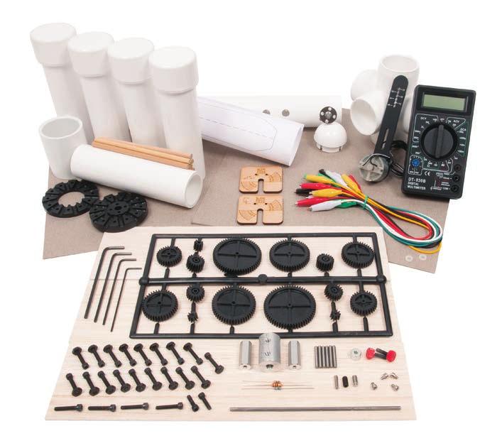
2 Cautionary and Warning Statements This kit is designed and intended for educational purposes only. Use only under the direct supervision of an adult who has read and understood the instructions provided in this user guide. Read warnings on packaging and in manual carefully. Always exercise caution when using sharp tools. Keep fingers away from rotating blades. Materials Included 2 nylon washers 7 PVC pipes 1 PVC pipe with attached motor hub 1 PVC cap 10 alligator cables 3 resistors /2" screws (use 7/64" hex key) /4" screws (use 7/64" hex key) 18 nuts standoff posts 2 thumbscrews 6 gear shaft pins 1 gear font 1 digital multimeter 2 angle gauges Items Required (not included) Glue Scissors Hobby knife Building the Turbine Stand 4 hex keys (7/64", 3/32", 1/16", and 5/64") 1 prop hub 1 turbine clamp ring 1 long metal axle /16" screw (use 3/32" hex key) 1 black setscrew (use 3/32" hex key) 1 large motor hub 1 small setscrew (use 3/32" hex key) 1 long setscrew (use 1/16" hex key) 1 motor mount 6 wooden dowel rods 3 balsa blades 5 chipboard sheets 1 blade design sample sheet 1 weight-lifting adapter Ruler Pen Tape 1. Slide a /2" screw into the top and bottom hole on the main PVC pipe from the opposite side. Screw each of them into a 6-32 standoff post (Figure 1). 2. Mount the prop hub to the motor hub with four /4" screws (Figure 2). Be sure to line up the holes. 3. Place the turbine clamp ring onto the prop hub and secure it with a /4" screw at the top and the bottom (Figure 3). Figure 1 Figure 2 Figure 3 2 Wind Turbine Experimenter s Kit User Guide V0116
.")


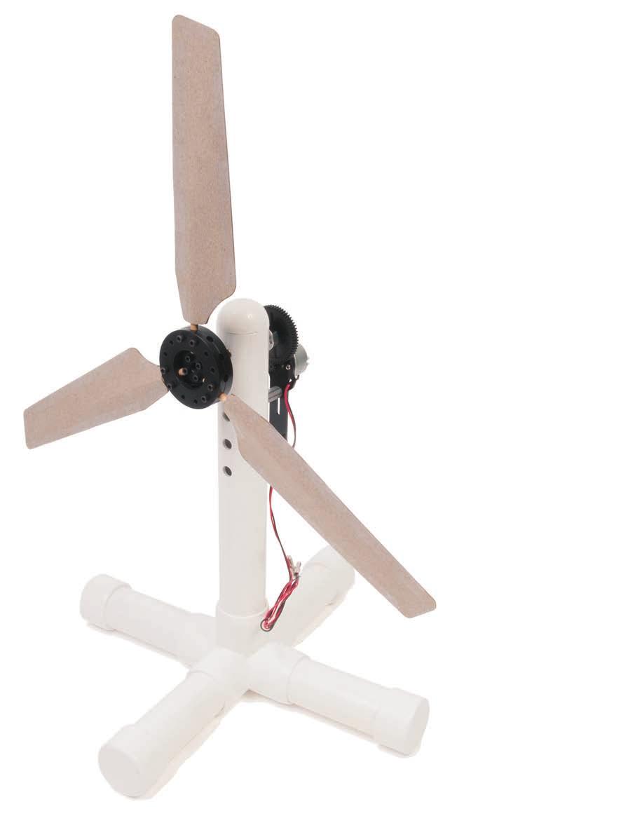
3 4. Build the PVC pipe stand. The main PVC pipe and four PVC pipe legs go into the five-way cross (Figures 4 and 5). The PVC cap fits in the top. Note: Extra PVC pipe pieces are included if you want the wind turbine to be taller. Figure 4 Figure 5 Attaching Gears to the Turbine Stand Note: 10T gears to 60T gears can be used with the Wind Turbine Experimenter s Kit. Make sure to remove the excess plastic from the gear so the teeth will mesh. Loosen and tighten the setscrew to make aligning the gears easier. For this example, we will use the 60T gear. 1. Remove the 60T gear from the gear font. 2. Place a gear shaft pin into the middle of the gear and make sure it is flush with one side (Figure 6). 3. Slide the 60T gear into the shaft hub on the back of the turbine and secure it with the set screw (Figure 7). 4. Slide a nylon washer onto each of the red thumbscrews. Mount the motor mount onto the standoff posts. Place a thumbscrew in the top hole, and then place a thumbscrew into the hole of the corresponding gear ratio (Figure 8). In this example, the correct hole is labeled 6:1 (Figure 9). Figure 6 Figure 7 Figure 8 Wind Turbine Experimenter s Kit User Guide V0116 Figure 9 3
.")
. Repeat two more times. 3. Measure an inch on three dowel rods.")


4 Creating Balsa Blades 1. Cut out the blade design you plan to use from the blade design sample sheet (Figure 10). 2. Trace the blade design onto a balsa blade and cut out the blade with a hobby knife (Figures 11 and 12). Repeat two more times. 3. Measure an inch on three dowel rods. Each blade needs at least one inch of a dowel rod exposed so the dowel rod can fit into the hub on the Wind Turbine Experimenter s Kit. 4. Put a line of glue into the middle of a balsa blade and glue the rod to it (Figure 13). Make sure an inch of the dowel rod sticks out at the bottom of the blade. Repeat two more times. Figure 10 Figure 11 Figure 12 Figure 13 4 Wind Turbine Experimenter s Kit User Guide V0116
.")


5 Creating Chipboard Blades 1. Cut out the blade design you plan to use from the blade design sample sheet. 2. Trace the blade design onto a chipboard sheet and cut out the blade with scissors (Figures 14 and 15). Repeat this five more times. Note: More than one blade can be created per sheet. 3. Measure an inch on three dowel rods. Each blade needs at least one inch of a dowel rod exposed so the dowel rod can fit into the hub on the Wind Turbine Experimenter s Kit. 4. Put a line of glue into the middle of a chipboard blade and glue the rod to it (Figure 16). Repeat two more times. 5. Tape a chipboard blade without a dowel rod to one with a dowel rod so that the dowel rod is in the middle. Tape the edges so there are no gaps (Figure 17). Repeat two more times. Figure 14 Figure 15 Figure 16 Figure 17 Wind Turbine Experimenter s Kit User Guide V0116 5
.")


6 Attaching Blades to the Hub 1. Push a blade into the prop hub until the bottom of the blade is flush with the center (Figure 18). Place a /4" screw on each side of the blade. Note: When you are placing blades into the prop hub, two screws must be used to fully secure the blade. 2. Repeat Step 1 to add the other blades (Figure 19). 1. Figure 18 Figure 19 Assembling and Using Angle Gauges Note: The angle gauge with the 1/8" offset is for balsa blades and the other blade angle gauge is for chipboard blades. 1. Place two /16" screws into the back of each angle gauge (Figure 20). 2. To use the gauges, press the screws on the gauge flush against the prop hub, look down the blade, and rotate to the desired angle (Figure 21). Figure 20 Figure 21 6 Wind Turbine Experimenter s Kit User Guide V0116


. 2. Insert the long axle into the large motor hub and secure by tightening the black")

7 Assembling Weight Add-On Note: This turbine setup is used to attach a weight with string to the weight-lifting adapter and long setscrew. You can use this setup to determine the amount of energy needed to lift the weight. 1. Remove the motor hub from the back of the turbine stand and attach the large motor hub in its place. Secure by tightening the small silver setscrew (Figure 22). 2. Insert the long axle into the large motor hub and secure by tightening the black setscrew (Figure 23). 3. Halfway down the long axle, attach the weight-lifting adapter and secure it with the long setscrew (Figures 24 and 25). Figure 22 Figure 23 Figure 24 Figure 25 Wind Turbine Experimenter s Kit User Guide V0116 7
8 Activity Ideas Determine the number of blades that provides the greatest power output for a given blade design. Use three or more different blade designs and determine whether the number of blades that provides the greatest power output for any given blade design is always the same. Compare blade output with various finishes applied (or not applied as the case may be): rough sanded, fine sanded, coated with lacquer, or coated with lacquer and then waxed and polished. Using the same basic blade design, determine the difference in output for various blade lengths (for example, 6", 8", 10"). Resistors, alligator cables, and a multimeter are included for your convenience so you can create your own activities. P.O. Box 1708 Pittsburg, KS Toll-Free Orders
T-Bot II. Challenge Set. Activity Guide. Cautionary and Warning Statements
 T-Bot II Challenge Set Activity Guide Cautionary and Warning Statements This kit is designed and intended for educational purposes only. Use only under the direct supervision of an adult who has read and
Sky Eagle. User Guide. Cautionary and Warning Statements
 Sky Eagle User Guide 60089 V0613 Cautionary and Warning Statements This kit is designed and intended for educational purposes only. Use only under the direct supervision of an adult who has read and understood
Start by building the example racer, then turn it into your own unique design.
 Start by building the example racer, then turn it into your own unique design. For use with TeacherGeek Air Racer Activity Pack, or Maker Cart. To find documents and activity materials, click here. Page
C-Bot. User Guide. Cautionary and Warning Statements
 C-Bot User Guide Cautionary and Warning Statements This kit is designed and intended for educational purposes only. Use only under the direct supervision of an adult who has read and understood the instructions
American Morse Equipment
 American Morse Equipment Thank you for purchasing an American Morse Porta Paddle-II Kit. We redesigned the original Porta Paddle for ease of assembly & provide all parts finished and ready for assembly,
Obtained from Omarshauntedtrail.com
 DaveintheGrave's Halloween Props Animated Crawling Skeleton Build a life-size skeleton torso that realistically crawls across the lawn one arm at a time. 1. Motor Base and Linkage Assembly BASE - I used
Super Sky Surfer 2000 Assembly Instructions
 Super Sky Surfer 2000 Assembly Instructions Note: Plug and Play version of the Sky Surfer comes with fuselage pre-glued and motor/servos installed. If you wish to route antennas or wires through the tail,
Lumber Smith. Assembly Manual. If you are having problems assembling the saw and need assistance, please contact us at:
 Lumber Smith Assembly Manual If you are having problems assembling the saw and need assistance, please contact us at: 804-577-7398 info@lumbersmith.com 1 Step 1 Safety Carefully read the Owners Manual.
installation guide
 JANUS INTERNATIONAL 1 866 562 2580 w w w. j a n u s i n t l. c o m 2000 2500 3000 installation guide RIGHT DRIVE END SHOWN LH OPPOSITE LEFT TENSION END SHOWN RH OPPOSITE PUSH-UP OPERATION 2000 2500 3000
Legacy Woodworking Machinery a division of Phantom Engineering. The Legacy CNC. Assembly Manual
 Legacy Woodworking Machinery a division of Phantom Engineering The Legacy CNC Assembly Manual New Orientation of the Legacy Step one: Re-orientation of the machine Remove the X-axis screw and supports.
Your kit contains the following parts. Please check your kit for any missing or damaged parts before starting construction.
 Your kit contains the following parts Please check your kit for any missing or damaged parts before starting construction COMPLETE KIT PARTS LIST 1 Plan Sheet #1 1 Plan Sheet #2 2 Decal Sheet 2 White Tissue
100mm (3in) Slide Stop Cut to 6mm (1/4in) Sections. Quantity: mm (10in) Skewers Quanity: 10. Material to Lift. Material for Blades.
 Slide Stop Cut to 6mm (1/4in) Sections. Quantity: mm (10in) Skewers Quanity: 10. Material to Lift. Material for Blades.") Wind Lift Page 1 The Activity This guide will take you through the process of creating a wind powered lift. You ll start by creating the stand. The lift mechanism, hub and blades are then added. Before
Wind Lift Page 1 The Activity This guide will take you through the process of creating a wind powered lift. You ll start by creating the stand. The lift mechanism, hub and blades are then added. Before
HD installation guide
 JANUS INTERNATIONAL 1 866 562 2580 www.janusintl.c o m 1950 1950HD installation guide RIGHT DRIVE END SHOWN LH OPPOSITE LEFT TENSION END SHOWN RH OPPOSITE PUSH-UP OPERATION 1950 1950HD SHOWN A rolling
WOLF PUP LOOM TM & WOLF PUP LT LOOM TM
 WOLF PUP LOOM TM & WOLF PUP LT LOOM TM Assembly Instructions FL3000 FL3006 FL3009 WOLF PUP WOLF PUP LT Find out more at schachtspindle.com Schacht Spindle Company 6101 Ben Place Boulder, CO 80301 p. 303.442.3212
ABM International, Inc.
 ABM International, Inc. Lightning Stitch required 1 1.0: Parts List head and motor assembly (Qty. 1) Reel stand (Qty. 1) Needle bar frame clamp (Qty. 1) Motor drive (Qty. 1) 2 Cable harness with bracket
DC Motor. Controller. User Guide V0210
 DC Motor Controller User Guide 59757 V0210 This kit provides a great exercise of intermediate soldering skills and creates a device that enables you to control various Pitsco motors, Tamiya gearboxes,
Hobby Lobby Zip Supplementary instructions Please refer to the included drawings while using these assembly instructions
 Materials needed: 15 or 30 minute epoxy Medium CA Masking tape Scotch tape Servo Tape Wax paper Tools Needed: Pencil or marker Flat building surface Hobby knife or razor blade 7/64" or 3mm drill bit 3/16"
Wind Pump Construction
 What Will You Need? Page 1 The following components can be found in your kit, and are needed to build one wind pump: 50 Tooth Gear* 40 Tooth Gear* 20 Tooth Gear* 10 Tooth Gear* Wheel Hub 300mm (~12in)
STAGE PAGE. 6 The left front door interior The right front wheel The right front seat back The right front wheel 37
 Pack 2 STAGE PAGE 6 The left front door interior 25 7 The right front wheel 29 8 The right front seat back 33 9 The right front wheel 37 10 The right front door 41 11 The right front door window 45 12
The Portable Open Source 3D Printer
 http://web.archive.org/web/201502142011/http://www.tantillus.org/build_3.html Page 1 of 12 captures 12 Oct 12 - Feb 15 The Portable Open Source 3D Printer Home Start Case X/Y Axis Extruder Z Axis Electronics
MAG-CONV Basic, 48, 48R & Midline Front Mount
 Parts Required: Tools Used: Mag Wheels Brakes Brake Rods Mounting Bracket Anti Tippers 7/16" Wrench Screw Driver Rubber Mallet 5/8 Wrench 5mm Allen Wrench Step Execution Figures 1 Remove front 5" total
The Useless Machine. DIY Soldering Edition. Instruction Guide v0004
 The Useless Machine DIY Soldering Edition Instruction Guide v0004 TM For the best outcome, follow each step in order. We recommend reading this guide entirely before you get started. Tools required: Soldering
This instruction manual is an in-depth look and explanation of how to assemble and install the Murphy Bed properly and efficiently.
 This instruction manual is an in-depth look and explanation of how to assemble and install the Murphy Bed properly and efficiently. Don t be put off by the size of the instruction manual as the large diagrams
VARIABLE SPEED WOOD LATHE
 MODEL MC1100B VARIABLE SPEED WOOD LATHE INSTRUCTION MANUAL Please read and fully understand the instructions in this manual before operation. Keep this manual safe for future reference. Version: 2015.02.02
3,500/4,500lb. Vertical Cable Feighner Lift
 3,500/4,500lb. Vertical Cable Feighner Lift CAUTION - PUT SAFETY FIRST 1. Before attempting to install or operate this lift, study and fully understand the proper operating procedures and safety precautions
It is highly recommended that you use a thread lock compound such as Loctite brand on all threads to keep them from vibrating loose.
 Installation instructions for FC12 Forward Controls for Kawasaki Vulcan 750 It is highly recommended that you use a thread lock compound such as Loctite brand on all threads to keep them from vibrating
Calf-Tel Pen System Assembly Instructions
 Calf-Tel Pen System Assembly Instructions (Instructions work for 4, 6, and the 7 Pen Systems) 1 ASSEMBLY OF PEN FRONT AND WALLS START THE ASSEMBLY BY LINING UP THE TWO UNI-DIRECTIONAL ARROWS IN THE TOP,
TeacherGeek Sumo Bot Vehicle Application Guide
 SUMO BOT VEHICLE EXAMPLE BUILD TeacherGeek Sumo Bot Vehicle Application Guide TeacherGeek, 011 SUMO BOT VEHICLE EXAMPLE BUILD TeacherGeek TeacherGeek s Sumo Bot Vehicle Activity is the perfect way to encourage
N. 15th Street, Middlesboro, KY FLIP TARP DUMP BODY INSTALLATION INSTRUCTIONS
 1-800-248-7717 1002 N. 15th Street, Middlesboro, KY 40965 FLIP TARP DUMP BODY INSTALLATION INSTRUCTIONS Congratulations on your purchase of a Mountain Flip Tarp Dump Body tarping system. With tarping systems
BABY WOLF LOOM. Assembly Instructions for Knocked-Down Looms
 BABY WOLF LOOM Assembly Instructions for Knocked-Down Looms BEFORE YOU BEGIN Please read through the directions before beginning to assemble your loom. Unpack the loom parts carefully. Do not throw away
Cautionary and Warning Statement. How a Trebuchet Works. Materials Included. Items Required (not included) Building the Base.
 Building the Base.") Cautionary and Warning Statement This kit is designed and intended for educational purposes only. Use only under the direct supervision of an adult who has read and understood the instructions provided
Cautionary and Warning Statement This kit is designed and intended for educational purposes only. Use only under the direct supervision of an adult who has read and understood the instructions provided
T R U E. Start by building the example boat, then turn it into your own unique design.
 T R U E Start by building the example boat, then turn it into your own unique design. For use with TeacherGeek Build-a-Boat Activity, or Maker Cart. To find documents and activity materials, click here.
Installation instructions for FC14S Forward Controls for Shadow ACE and Aero 1100
 Installation instructions for FC14S Forward Controls for Shadow ACE and Aero 1100 It is highly recommended that you use a thread lock compound such as Loctite brand on all threads to keep them from vibrating
model tsa-sa48 Sliding Crosscut Table installation guide
 model tsa-sa48 Sliding Crosscut Table installation guide A Note About Color Variations Among Anodized Aluminum Components Congratulations on the purchase of this SawStop Sliding Crosscut Table. We at SawStop
OWNER S MANUAL. But that s just half the story. The fence INCRA Miter Gauge really does work
 From the makers of the INCRA JIG! Please read this owner s manual before use and keep it at hand for reference. Your new INCRA Miter Gauge at long last solves that frustrating problem all too familiar
Thank you for purchasing out product! *Please read these instructions and follow them step by step. *
 Page 1 of 7 AD17 AA DS 4 X 16 T12 Thank you for purchasing out product! *Please read these instructions and follow them step by step. * STEP 1. Slide two support posts (REF. # 24) into the two outside
OPERATOR'S MANUAL 46" SNOW BLADE. Model Numbers OEM IMPORTANT: READ SAFETY RULES AND INSTRUCTIONS CAREFULLY
 OPERATOR'S MANUAL 46" SNOW BLADE Model Numbers 190-833-OEM IMPORTANT: READ SAFETY RULES AND INSTRUCTIONS CAREFULLY MTD PRODUCTS INC. P.O. BOX 368022 CLEVELAND, OHIO 44136-9722 PRINTED IN U.S.A. FORM NO.
Activity Instructions - Classroom Wind Farm
 Wind Power - Classroom Wind Farm Activity Instructions - Classroom Wind Farm The purpose of this activity is for students to build their own windmill generator, which will then be one unit of the classroom
ASSEMBLY GUIDE. Mia Narrow Bookcase
 ASSEMBLY GUIDE Mia Narrow Bookcase Components: Upon unpacking your bookcase from it s delivery box, you should have the pieces shown. Follow the steps on the next pages to assemble your new bookcase. Step
PORTA-DOCK, INC. AP17 APD DS 4 X 16 T12 AW17 CPD DS 4 X 16 T12
 Page 1 of 7 PORTA-DOCK, INC. AP17 APD DS 4 X 16 T12 AW17 CPD DS 4 X 16 T12 *For Beige Decking Add the Letter B to Model* Thank you for purchasing out product! *Please read these instructions and follow
Citabria Pro. Aerobatic Parkflyer. by Joel Dirnberger
 Citabria Pro Aerobatic Parkflyer by Joel Dirnberger Revision C: December 21, 2004 Citabria Pro Building Instructions Length: Wingspan: Wing Area: Flying Weight: Wing Loading: Functions: Specifications:
OWNER S MANUAL CONTENTS. The only table saw fence with Automatic Positioning Control TM
 The only table saw fence with Automatic Positioning Control TM OWNER S MANUAL Please read this owner s manual before use and keep it at hand for reference. Note: The INCRA TS II system consists of three
MPA-9000 Universal Ceiling Projector Mount Kit
 I N S T R U C T I O N M A N U A L Universal Ceiling Projector Mount Kit The Universal Ceiling Projector Mount provides a unique, simplified method of ceiling mounting your inverted projector. This low
The Useless Machine. Parts Only - Build Guide v0001
 TM The Useless Machine Parts Only - Build Guide v0001 For the best outcome, follow each step in order. We recommend reading this guide entirely before you get started. Tools required: One phillips screwdriver,
A59 APD & A86 CPD 5'X 16' SW ALUMINUM PORTA-DOCK
 Page 1 of 5 PORTA-DOCK, INC. A59 APD & A86 CPD 5'X 16' SW ALUMINUM PORTA-DOCK *For Beige Decking Add the Letter B to model* Thank you for purchasing our product! *Please read these instructions and follow
Range height adjustable assembly
 Table of contents Digital handset operation 3 Height adjustable bench kit 4-5 Cable carrier 6 Ganging tray and ganging rail 7 Height adjustable return frame kit 8 Cable entry pole 9 24 and 30 d worksurfaces
Large Wood Windmill Assembly Instructions
 CROW S NEST (TOP VIEW) TOWER (SIDE VIEW) 0 QTY 2 2 ITEM QTY 2 QTY QTY 8 QTY 8 QTY 4 TOP TOP TOP 47 9 QTY 4 QTY 4 QTY 4 QTY 4 QTY 4 ITEM 6 ITEM 7 ITEM 8 ITEM 3 ITEM 9 ITEM 4 ITEM 2 ITEM 5 47 Leg QTY 4 42.5
INSTRUCTION MANUAL AND PARTS LIST MODEL 14-10
 VERTICAL BAND SAWS INSTRUCTION MANUAL AND PARTS LIST MODEL 1-10 DAKE/PARMA WHEN ORDERING PARTS GIVE COMPLETE SERIAL NUMBER OF MACHINE GIVE PART NUMBER AND NAME GIVE AMOUNT REQUIRED Unless the above data
Sliding Crosscut Table installation guide
 Sliding Crosscut Table installation guide model tsa-sa48 A Note About Color Variations Among Anodized Aluminum Components Congratulations on the purchase of this SawStop Sliding Crosscut Table. We at SawStop
This manual will aid in the assembly of the FireBall V90 and FireBall X90. The assembly of both machines will be identical, unless specified.
 This manual will aid in the assembly of the FireBall V90 and FireBall X90. The assembly of both machines will be identical, unless specified. Step #1 Lay all parts out to verify quantities. (2) 2 x 25-1/4
SCC Inc. VA Series. Technical Instructions. Document No. VA-7000 February 1, VA Valve Actuator Assemblies with VRG Butterfly Valves.
 February 1, 2016 VA Valve Actuator Assemblies with VRG Butterfly Valves Description Features Application VA valve actuator assemblies include a Siemens SQM actuator reliably mounted to a VRG butterfly
VARIABLE SPEED WOOD LATHE. Model DB900 INSTRUCTION MANUAL
 VARIABLE SPEED WOOD LATHE Model DB900 INSTRUCTION MANUAL 1007 TABLE OF CONTENTS SECTION...PAGE Technical data.. 1 General safety rules....1-3 Specific safety rules for wood lathe.....3 Electrical information.4
WARNING! ETCHED PARTS CONTAINED IN THIS KIT HAVE SHARP POINTS, EDGES AND CORNERS.
 MPD18 chassis build instructions K A (see below for details) J I G H L C D F E B M Parts list: Ident Quantity A Etched Nickel/Silver fret 1 B Wheel sets 2 C Worms 2 D Worm gears 2 E Shaft adapters 2 F
Adjustable Hammered Dulcimer Stand
 Adjustable Hammered Dulcimer Stand Musicmaker s Kits (Hwy 36 behind Joseph s Restaurant) P.O. Box 2117 Stillwater MN 55082 651 439 9120 www.harpkit.com PARTS LIST: 1 Set of Assembly Instructions A. 2 front
Model 209 Fireback Replacement
 Model 209 Fireback Replacement Please read all the instructions before you begin the procedure. Confirm that you have all the necessary tools and materials. If you have any questions, technical support
OWNER S MANUAL CONTENTS. The only table saw fence with Automatic Positioning Control TM
 The only table saw fence with Automatic Positioning Control TM OWNER S MANUAL Please read this owner s manual before use and keep it at hand for reference. Note: The INCRA TS III system consists of three
EllisSaw.com. EllisSaw.com P.O. Box Verona, WI
 P.O. Box 9019 Verona, WI 9-019 GENERAL OPERATING & SAFETY INSTRUCTIONS * READ INSTRUCTIONS BEFORE USE * CAUTION: Disconnect power supply cord from power source when doing repair work or changing belt.
Orbital Test Stand. Operations and Assembly Manual. Department of Mechanical Engineering Northern Arizona University Flagstaff, AZ 86011
 Orbital Test Stand Operations and Assembly Manual Department of Mechanical Engineering Northern Arizona University Flagstaff, AZ 86011 TABLE OF CONTENTS 1.0 Components List... 2 2.0 Assembly Instructions...
INSTALLATION INSTRUCTIONS
 INSTALLATION INSTRUCTIONS TM X-10 Type 1F HIGH SECURITY ELECTRONIC LOCK Table of Contents Introduction... 1 Basic Tools and Materials Needed... 1 Lock Parts for Installation... 1 Installation Kit Contents...
Plug-n-Show Stake Down Pixel Tree Kit 16 strips of 25 pixels Assembly Instructions
 www.lightorama.com Plug-n-Show Stake Down Pixel Tree Kit 16 strips of 25 pixels Assembly Instructions Read all instructions before you start Kit assembly! STEP 1. Check that all parts are included Parts
SECTION 9: PARTS. Table Breakdown REF PART # DESCRIPTION REF PART # DESCRIPTION
 SECTION 9: PARTS Table Breakdown 1 2 3 4 5 6 7 8 9 10 11 12 13 14 15 16 17 18 19 20 21 22 23 24 23 25 17 26 27 8 1 P0675001 CAP SCREW M8-1.25 X 30 15 P0675015 SUPPORT BLOCK 2 P0675002 TABLE SUPPORT BLOCK
ABM International, Inc. Navigator Assembly Manual
 ABM International, Inc. 1 1.0: Parts List Tablet (Qty. 1) Tablet mount (Qty. 1) NOTE: Mount may appear and operate different then image below Control Box (Qty. 1) Motor Power Supply (Qty. 1) 2 X-axis motor
Instruction Manual 2 BLADE CLASSIC. Scan the QR code with a mobile device to view the installation video.
 Instruction Manual 2 BLADE CLASSIC Scan the QR code with a mobile device to view the installation video. www.max-prop.com 1) INTRODUCTION: Thank you for having chosen a MAX PROP automatic feathering propeller
Customer Notice: Congratulations again on your SawStop purchase, and thank you! -SawStop Tualatin, OR
 Customer Notice: Congratulations on the purchase of this Sliding Crosscut Attachment. As the owner of a SawStop saw, you are familiar with our high standards for quality, fit and finish. Different from
v1.0 ASSEMBLY GUIDE Mia Wide Bookcase
 v1.0 ASSEMBLY GUIDE Mia Wide Bookcase Components Upon unpacking your bookcase from it s delivery box, you should have the pieces shown. Follow the steps on the next pages to assemble your new bookcase.
MOTOR & BULK HEAD. A Manual for Repair and Maintenance Technicians
 MOTOR & BULK HEAD A Manual for Repair and Maintenance Technicians CAUTION This manual is designed to help technicians who are already experienced in workshop procedures and know how to handle tools. Only
PORTABLE ADJUSTABLE BASKETBALL SYSTEM
 Instruction Manual PORTABLE ADJUSTABLE BASKETBALL SYSTEM P A R T S L I S T 5 1/2 and 8 safe play clearance Item Qty Description Item Qty Description A 1 Portable Base Assembly M 4 1/2 Lock Nut B 2 Front
RIPPER PEDAL. Bearing / Axle Replacement. ( Disassembly )
") RIPPER PEDAL Bearing / Axle Replacement ( Disassembly ) 1 1. Use good quality tools to avoid stripping screw sockets. 2. When servicing your pedals, work on one side at a time to prevent parts from mixing
RIPPER PEDAL Bearing / Axle Replacement ( Disassembly ) 1 1. Use good quality tools to avoid stripping screw sockets. 2. When servicing your pedals, work on one side at a time to prevent parts from mixing
MULTI-ACTIVITY PLAY TABLE
 ASSEMBLY INSTRUCTIONS! WARNING: CHOKING HAZARD - Small parts. Not for children under 3 years.! CAUTION: Adult assembly required. C 2006 Melissa and Doug, Inc. All Rights Reserved www.melissaanddoug.com
H2-50 Hydrogen Generator Field Update
 This field update is intended to provide extra protection in the event the H2 generation cell fractures or cracks. Please add the additional parts to your H2-50 as soon as possible. Please take a digital
RC-TEK Ltd. SKYSHARK 450 REFERENCE MANUAL. Copyright 2007 RC-TEK, All Rights Reserved
 RC-TEK Ltd. SKYSHARK 450 REFERENCE MANUAL Frame Assembly On each page of this manual the parts required for each step will be listed below along with a set of images showing the stages of each part of
Side Winder R o u t e r L i f t.
 Woodpeckers PRECISION WOODWORKING TOOLS Side Winder R o u t e r L i f t. INSTALLATION INSTRUCTIONS The wrench handle must be pointing left in order to fully insert or remove it. Lift Wrench Once fully
Read through the Operator's Manual carefully and understand the content before using the machine.
 Operator's Manual 123L J-Handle Kit Read through the Operator's Manual carefully and understand the content before using the machine. These instructions supplement the instructions that were included with
NOT ALLOW YOUNG CHILDREN TO PLAY WITH THIS TOY UNSUPERVISED.
 SNAPPING ALLIGATOR This wooden toy is great for parents or grandparents to play with young children. Hold by the tail and move the alligator slowly along with the front wheel slightly off the ground and
LSU Duct Liner Sizer. LSU Duc DUCT LINER SIZER MACHINERY DIVISION OWNER S MANUAL
 LSU Duct Liner Sizer LSU Duc DUCT LINER SIZER OWNER S MANUAL MACHINERY DIVISION ASSEMBLY INSTRUCTIONS IMPORTANT: DO NOT TIGHTEN THE NUTS UNTIL THE UNIT IS COMPLETELY ASSEMBLED. A) Assemble the cutting
RANGE DIGITAL HANDSET OPERATION. 1. Panel. 2. Initialization Procedure. 3. Move Up & Down. 4. Set Memory Positions. 5. Move to the Memorized Positions
 INSTRUCTION SHEET #2577INS PART #1730534 DIGITAL HANDSET OPERATION OPERATION INSTRUCTIONS 1. Panel 1 Button: Preset 1 2 Button: Preset 2 3 Button: Preset 3 S Button: Select Display: Reads in 1 / 2 " Increments
Shop Style Miter Saw Stand Kit
 Quality Power Tool Accessories OWNER S MANUAL Assembled Unit Shown Without Shelves & Wings Assembled With Shelves & Wings Shop Style Miter Saw Stand Kit Model 2850 IMPORTANT Read and understand all safety
/ Rudder Installation Guide
 / Rudder Installation Guide Parts List Part # Part Description Qty Part # Part Description Qty 1030 Plastic Bead 1 1195 Rope; 1/8" Black Nylon 1 @ 9 1044 1/4-20 x 5/8" Pan Head Bolt 2 1353 Sliding Track
Zen Toolworks CNC Carving Machine DIY Kit User Installation Manual
 User Installation Manual Visit Us At: http://www.zentoolworks.com or http://www.zentoolworks.com/zenwiki/mediawiki Contact Us At: zentoolworks@gmail.com 1 P-01, Nema 17 Stepper Motor, 3 P-02, Motor Shaft
WRIGHT FLYER 1 INSTRUCTIONS FOR THE D10LC KIT
 WRIGHT FLYER 1 INSTRUCTIONS FOR THE D10LC KIT Manufactured in the USA by Easy Built Models PO Box 681744, Prattville, AL 36068-1744 Visit us at www.easybuiltmodels.com Easy Built Models GLUE METHODS Always
 www.wildmanconstruction.com Changing your toilet is an easy project that should take half a day or less. The most common toilet has a separate tank that mounts on top of the bowl. These instructions apply
Instructions & Parts SM100B SM400 K025S1 K005
 Instructions & Parts SM100B SM400 K025S1 K005 Table of Contents 2 SM100B/SM400 Manual Engraver Machine Diagram Pantograph Operation Setup & Layout Engraving & Changing Cutters Adjusting Depth of Cut &
WILDING WALLBEDS INSTALLATION INSTRUCTION Side Mount
 WILDING WALLBEDS INSTALLATION INSTRUCTION Side Mount For Wallbed models: Do-It-Yourself Insturction booklet C92 WARNING! ALL MURPHY/WALLBED SYSTEMS CONTAIN STORED ENERGY. FAILURE TO USE AND FOLLOW THESE
LSU Duct Liner Sizer. LSU Duct UCT LINER SIZER MACHINERY DIVISION OWNER S MANUAL
 LSU Duct Liner Sizer LSU Duct LDUC UCT LINER SIZER OWNER S MANUAL MACHINERY DIVISION assembly Instructions IMPORTANT: DO NOT TIGHTEN THE NUTS UNTIL THE UNIT IS COMPLETELY ASSEMBLED. A) Assemble the cutting
Portable System Owners Manual
 Portable System Owners Manual Customer Service Center N53 W24700 South Corporate Circle Sussex, WI 53089 U.S.A. Adult Assembly Required. This manual, accompanied by sales receipt, should be saved and kept
43in EPP Acrocub Instruction Manual
 43in EPP Acrocub Instruction Manual Specifications Wingspan: 43.3in (1100mm) Length: 41.3in (1050mm) Flying Weight: Approx. 1.5lb (670g) Dear Customer, Congratulations on your purchase of 43in EPP Acrocub
Building Instructions Diva cabin boat
 Building Instructions Diva cabin boat Order no. 3093/00 aero-naut Modellbau Stuttgarterstr. 18-22 D-72766 Reutlingen / Germany http://www.aero-naut.com 1 For pictured building instructions please see the
SERIES I MILLING MACHINES
 INSTALLATION, OPERATION, MAINTENANCE, AND PARTS LIST SERIES I MILLING MACHINES TP5260 Revised: August 29, 2005 Manual No. M-450 Litho in U.S.A. Part No. M -0009500-0450 June, 2003 MAINTENANCE PROCEDURES
Assembly Instructions Please keep for future reference Inspire 40
 Assembly Instructions Please keep for future reference Inspire 40 Version 3 : 28/07/2014 Important - Please read these instructions fully before starting assembly ALR2902 Safety and Care Advice Important
Two Panel Frameless Bypass Door
 INSTALLATION INSTRUCTIONS Two Frameless Bypass Door Series 00 Please Record Model Number From Carton Label Here Please read these instructions carefully to familiarize yourself with the required tools,
Pro-Doweling Kit USER S MANUAL #840. Visit us at
 Pro-Doweling Kit USER S MANUAL #840 99 Washington Street Melrose, MA 02176 Phone 781-665-1400 Toll Free 1-800-517-8431 Visit us at www.testequipmentdepot.com Please read this manual carefully and thoroughly
Traditional Wall Mounted Potfiller
 TOOLS NEEDED FOR INSTALLATION 1/4 hex wrench (provided in installation kit) 3/32 hex wrench (provided in installation kit) Pencil or marker PTFE tape Small level, or carpenters square Power Drill with
installation guide 1 GUIDE#: pwb-assault-001
 assault WAKEBOARD tower installation guide INSTALLATION SUPPORT 1 important information This Aerial wakeboard tower fits motor boats with 76-108 inch wide beam widths. This measurement is taken from the
Modifying the Hextronik HX5010 Servo Motors for Babuinobot 1.0
 Modifying the Hextronik HX5010 Servo Motors for Babuinobot 1.0 Brett Nelson January 2010 1 Converting the Hextronik HX5010 to a Geared DC Motor The following pages will describe step by step the process
Build the Spitfire: Step-By-step. Pack 7 Stages 61-71
 Pack 7 Stages 61-71 1 Stage Contents Page Number 61 212-215 62 216-218 63 219-221 64 222-224 65 225-228 66 229-231 67 232-235 68 236-238 69 239-241 70 242-245 71 246-249 Editorial and design by Continuo
Assembly Instructions. Table of Contents
 HQ Little Foot Assembly Instructions Back of Handi Quilter, Inc. 501 North 400 West North Salt Lake, UT 84054 1-877-697-8458 Front of 2015 Handi Quilter, Inc. www.handiquilter.com Printed in the United
HEAVY DUTY GASKET CUTTER
 HEAVY DUTY GASKET CUTTER GUIDE TO PERFECT GASKETS CUTTING GASKETS 1 TO 13 IN DIAMETER: 1. Lay out gasket outer diameter (OD), inner diameter (ID) and bolt holes on template or gasket material. See section
Pistol Pete s Truck Bed Lighting w/recon Lights
 PARTS LIST Pistol Pete s Truck Bed Lighting w/recon Lights # Description 1 Four 3/16 X 2 toggle bolts 2 Four Fender washers 1.5 x 3/8 (SS) 3 1 wide x 1/8 thick aluminum stock to make brackets 4 Four 3/16
Woodline USA Woodline Spacer Fence System
 Woodline USA Woodline Spacer Fence System MADE IN THE USA Includes: (1) ¼ Spacer Fence (1) 3/8 Spacer Fence (1) ½ Spacer Fence (1) Hardware Package (1) 3 Piece Brass bar set (2) Setup Blocks Visit Us Online
TYGER GUARD. Parts List BEFORE INSTALLATION WARNING TG-GD6D /7. Tyger Guard. Tube Brackets (Bull Bar) passenger or driver side
 passenger or driver side") TYGER GUARD TM BEFORE INSTALLATION TG-GD6D60068 READ INSTRUCTIONS CAREFULLY BEFORE STARTING INSTALLATION. REMOVE CONTENTS FROM BOX AND VERIFY ALL PARTS ARE PRESENT. ASSISTANCE IS RECOMMENDED. CUTTING IS
TYGER GUARD TM BEFORE INSTALLATION TG-GD6D60068 READ INSTRUCTIONS CAREFULLY BEFORE STARTING INSTALLATION. REMOVE CONTENTS FROM BOX AND VERIFY ALL PARTS ARE PRESENT. ASSISTANCE IS RECOMMENDED. CUTTING IS