WireCrafters, LLC. General Information
|
|
|
- Amos Hunt
- 5 years ago
- Views:
Transcription

1
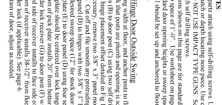
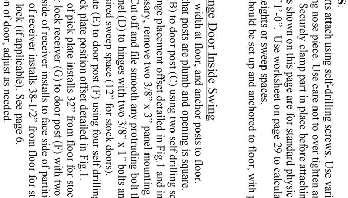
2 WireCrafters, LLC. General Information 6208 Strawberry Lane 502/ Louisville, Kentucky / FAX The following General Installation Instructions should be used as a guide for installing WireCrafters Style 840 Partitions. Because of the varying job site conditions, and infinite layout possibilities, there is no recommended way to install the product. Good common sense and proper safety precautions must be used during installation. The product may be unstable during installation; proper temporary bracing should be used until all hardware is tightened and the product is properly anchored to the floor. Permanent field bracing may be installed at installer s/owner s discretion. Install problems arising from job site conditions should be referred to a professional installer. Refer product assembly questions to WireCrafters. TOOLS RECOMMENDED Chalk line & marker Drill with adjustable clutch and 3/8 nut driver (2) Step ladders if installing ceiling Tape Measure Hammer Drill with 3/8 masonry bit (2) C clamps or Vise-Grip type clamps Level (2) 9/16 open end wrenches and/or #1 & #2 Phillips Screw Driver Hacksaw (2) 9/16 deep socket ratchets 1/2 deep socket or 1/2 open end wrench SELF DRILLING SCREW INSTALLATION RECOMMENDATIONS When installing self drilling screws use a standard variable speed screw gun equipped with an adjustable clutch or depth locating nose piece. Take care not to over tighten or strip, set drill accordingly. DO NOT USE IMPACT TYPE GUN WHEN INSTALLING SELF DRILLING SCREWS. Securely clamp component parts in place before attaching with self drilling screws. INSTALLER TIPS 1. Installation is best accomplished with a two or three person crew. 2. Before starting, review all installation instructions pertinent to your layout (i.e. panels, doors, etc.) 3. Face Side of the partition is the outside, where nuts and bolts will NOT be visible or accessible. Inside of the partition has one leg of the panel frame pointing in. Assembly hardware will be on the inside of most layouts. 4. Panels install horizontally between posts, 2 mesh opening should be parallel with floor. 5. Identify all panels by part number. If possible stage parts where they will be installed. 6. Special size panels have metal tags on the mesh and are referenced on drawing. 7. Make sure all posts are installed plumb (vertically perpendicular to floor). Shims (not provided) may be necessary. 8. Use a 3-1/4 spacer block (not provided) to support far end of panel during setup. 9. Begin installation process at a building wall, end or corner of layout. 10. Gauge hinge door opening by width of transom panel. 11. Gauge slide door opening by door width (e.g. 48 between posts for 4 wide slide door). When necessary, slide door openings may be narrowed to adjust length of adjacent run. 12. Standard hinge, double hinge, and slide doors are universal and may be installed inside or outside swing, left or right hand. Dutch and special doors are not universal and must be installed as shown out on drawing. 13. Installer should cut off any bolts or hardware protruding into aisle ways or around door openings. 14. Installer should touch up all nicks, marks, and scratches with touch up paint provided. Revision 1.0 8/21/02
3
4
5
6
7
8
9
10
11
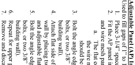
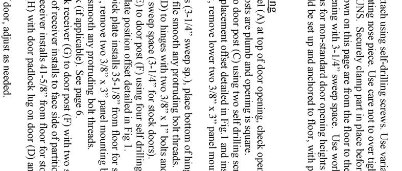
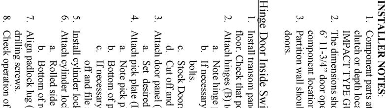
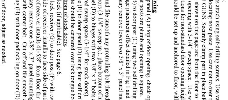
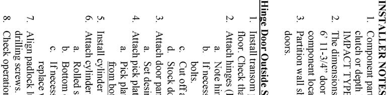
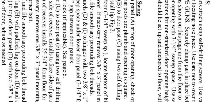
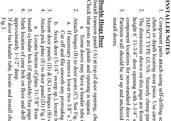
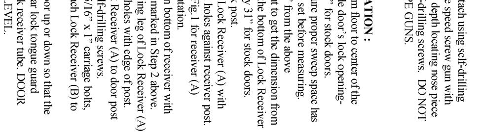
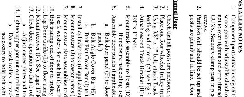
12 WireCrafters Outside Slide Door INSTALLER NOTES 1. Doors wider than 5 are made up of multiple door panels (see page 16), and use two pieces of track spliced at Splice Track Bracket (A). 2. Component parts attach using self-drilling screws. Use variable speed screw gun with adjustable clutch or depth locating nose piece. Use care not to over tighten and strip threads. DO NOT USE IMPACT TYPE GUNS. Securely clamp part in place before attaching with self drilling screws. 3. Partition wall should be set up and anchored to floor. It is CRITICAL that posts are plumb and in line. Door opening should be square. Outside Slide Door 1. Check that door posts are anchored and plumb. 2. Using a 3/8 x 3 bolt, install Splice Track Bracket (A) on face side of door post (B) opposite door receiver post (C). Note: if enclosure has ceiling use a 3/8 x 1 bolt to attach bracket see Fig Place two 4 wheel trolley trucks (F) into track (D). Using one 3/8 x 1 bolt, attach track bracket (G-1) to track. a. Check that trucks roll freely in track. 4. Slide open end of track (D) into Splice Track Bracket (A). Using one 3/8 x 3 bolt, attach track bracket (G-1) to receiver post (C) see Fig Invert Track Bracket (G-2) and attach to far end of Track (D) using one 3/8 x 1 bolt. If end of track aligns with post, do not invert track bracket. a. For doors wider than 5 i. Attach inverted bracket to far end of second track section. ii. Slide open end of second track section (D) into open end of Splice Track Bracket (A). 6. Using one 3/8 x 1-1/2 bolt and two Slide Door Shims, attach the inverted track bracket on the far end of Track (D) to the wire mesh panel. a. Per Fig. 3 place one flat Slide Door Shim between the Track Bracket (G-2) and the mesh, and the other Slide Door Shim on the inside of the mesh and fasten in place with one 3/8 x 1-1/2 bolt and hex nut. TRACK MUST BE LEVEL. b. Should Track Bracket (G-2) align with post, attach upright track bracket to post with 3/8 bolt. 7. For doors wider than 5 or taller than 8, assemble door panels to form door assembly. See Slide Door Panel Assembly page Hang door (I) on Trolley Trucks. a. Two 9/16 round holes on top of door assembly match trolley bolts. b. Trolley bolts should have one nut above and below door frame; upper jam nut should be backed off until door operation is finalized. 9. Raise door to desired sweep space using lower trolley nut. a. Stock doors without lower angle cover bar have 3-1/4 sweep space. b. Stock doors with lower angle cover bar have 1-3/4 sweep space. c. Door must be level for proper operation. 10. Lag Door Guide (M) to floor with two floor anchors see Fig Door should slide freely, if not check that trolley trucks are properly aligned in track. 12. If applicable, install cylinder lock in door, see page Install Lock Receiver (N). See Fig 5. and slide door receiver instructions on page Fine tune door by tightening/loosening trolley truck nuts. a. When door operates smoothly and locks consistently, tighten top jam nut. b. Be sure not to cock trolleys sideways when tightening jam nut. It may be necessary to hold bolt with pliers while tightening jam nut. Revision 1.0 8/21/02
13
14 WireCrafters Inside Slide Door INSTALLER NOTES 1. Doors wider than 5 are made up of multiple door panels (see page 16), and use two pieces of track spliced at Track Bracket (A). 2. Component parts attach using self-drilling screws. Use variable speed screw gun with adjustable clutch or depth locating nose piece. Use care not to over tighten and strip threads. DO NOT USE IMPACT TYPE GUNS. Securely clamp part in place before attaching with self drilling screws. 3. Partition wall should be set up and anchored to floor. It is CRITICAL that posts are plumb and in line. Door opening should be square. Inside Slide Door 1. Check that door posts are anchored and plumb. 2. Using a 3/8 x 3 bolt and one Slide Door Shim(O), install Splice Track Bracket (A) on inside of door post (B) opposite door receiver post (C). Place the shim between the bracket and the post. Note: If enclosure has ceiling, use a 3/8 x 1 bolt to attach bracket see Fig Place two 4 wheel trolley trucks (F) into track (D). Using one 3/8 x 1 bolt attach track bracket (G1) to track. a. Check that trucks roll freely in track. 4. Slide open end of track (D) into Splice Track Bracket (A). Using one 3/8 x 3 bolt and one Slide Door Shim (O), attach track bracket (G1) to inside of receiver post (C) see Fig Invert Track Bracket (G2) and attach to far end of Track (D) using one 3/8 x 1 bolt. If end of track aligns with post, do not invert track bracket. a. For doors wider than 5 i. Attach inverted bracket to far end of second track section. ii. Slide open end of second track section (D) into open end of Splice Track Bracket (A). 6. Using one 3/8 x 2-1/2 bolt, one Slide Door Shim and one 2 Slide Door Spacer (P), attach the inverted track bracket on the far end of Track (D) to the wire mesh panel. TRACK MUST BE LEVEL. a. Per Fig. 3 place one 2 Slide Door Spacer between the Track Bracket and the mesh, and the Slide Door Shim on the outside of the mesh and fasten in place with one 3/8 x 2-1/2 bolt and hex nut. b. Should Track Bracket (G-2) align with post, attach upright track bracket to post with 3/8 bolt. 7. For doors wider than 5 or taller than 8, assemble door panels to form door assembly. See Slide Door Panel Assembly page Hang door (I) on Trolley Trucks. a. Two 9/16 round holes on top of door assembly match trolley bolts. b. Trolley bolts should have one nut above and below door frame; upper jam nut should be backed off until door operation is finalized. 9. Raise door to desired sweep space using lower trolley nut. a. Stock doors without lower angle cover bar have 3-1/4 sweep space. b. Stock doors with lower angle cover bar have 1-3/4 sweep space. c. Door must be level for proper operation. 10. Lag Door Guide (M) to floor with two floor anchors see Fig Door should slide freely. If not check that trolley trucks are properly aligned in track. 12. If applicable, install cylinder lock in door, see page Install Lock Receiver (N). See Fig.5 and Slide Door Receiver instruction on page Fine tune door by tightening/loosening trolley truck nuts. a. When door operates smoothly and locks consistently, tighten top jam nut. b. Be sure not to cock trolleys sideways when tightening jam nut. It may be necessary to hold bolt with pliers while tightening jam nut. Revision 1.0 8/21/02
15
16
17
18
19
20

21
22
23
24
25
26
27
28
29 NON-STOCK COMPONENT LOCATION WORK SHEET All locations are from floor to bottom of component Fill in blanks with appropriate Dimensions before starting calculations Sweep Space Door Leaf Height Center Line of Door (Divide Door Leaf Height in Half) Center Line of Tongue Hole in Door Leaf Bottom Door Leaf Height (Dutch Door Only) Top Door Leaf Height (Dutch Door Only) Hinge Door Components Bottom Hinge Location : Sweep Space + 4 = Center Hinge Location : (Sweep Space + Center line of Door) then subtract 2 = Top Hinge Location : (Door Height + Sweep Space) then subtract 8 = Receiver Location : (Center Line of Tongue Hole in Door Leaf + Sweep Space) then Subtract 3 1/2 = Angle Pick Plate : (Center Line of Tongue Hole in Door Leaf + Sweep Space) then Subtract 10 = (Inside Swing Only) Dutch Door Components Bottom Hinge Bottom Leaf : Sweep Space + 4 = Top Hinge Bottom Leaf : (Sweep Space + Bottom Door Leaf Height) then subtract 8 = Bottom Hinge Top Leaf : Bottom Door Leaf Height + Sweep Space + 5/8 + 4 = Top Hinge Top Leaf : (Bottom Door Leaf Height + Sweep Space + 5/8 + Top Door Leaf Height) then subtract 8 = Receiver Location : (Center Line of Tongue Hole in Door Leaf + Sweep Space) Subtract 3 1/2 = Revision 1.0 8/21/02
30 WireCrafters Thanks for using WireCrafters woven wire partitions. Tool Cribs Storage Lockers Machine Guards Mezzanine Rails Pallet Rack Backs Security Enclosures
31 WireCrafters We appreciate your business, and hope to work with you on future projects. A significant effort went into creating this instruction booklet and we are interested in your comments regarding it. Please answer the questions below, tear off this page, and fax it to us at , or fold on the dotted lines, tape shut, and drop in the mail. We welcome your suggestions and observations. Drawing or B/L Number Date Installed Did you find any of the instructions confusing? If so which one(s) and why. Generally, the instructions are (circle one): Too detailed About right Too general Did you encounter any assembly problems? If so please describe. Did the product arrive in good condition? Are you satisfied with the product? If not please explain. Other Comments
Installation Instructions
 Contents Page General Information and Installer Tips.......... 2 Panels & Posts............................. 3 Enclosure Description..................... 4 Hinge Door Hardware................... 4-5 Step-by-Step
LPR System Installation instructions
 Toll LPR System Installation instructions 1 General Information The following installation instructions should be used as a guide for installing Folding Guard LPR System. Good common sense and appropriate
Qwik-Fence Installation Instructions
 Qwik-Fence Installation Instructions 1 Tools Required The following installation instructions should be used as a guide for installing Folding Guard Qwik-Fence Partitions. Good common sense and appropriate
EZ-MATRIX I N S TA L L AT I O N I N S T R U C T I O N S EZ-MATRIX
 TM I N S TA L L AT I O N I N S T R U C T I O N S READ THESE INSTRUCTIONS page 2 Installer Tips: Installation is best completed with the help of one or two people. Prior to beginning, please read through
MATRIX GUARD. I nstallation I nstructions TERMS AND CONDITIONS. Call or visit
 TERMS AND CONDITIONS It is the intent of Wireway Husky Corp. that any product received by our Customers fully meets their expectations. MATRIX GUARD Wireway Husky product is Marketed and Distributed by
Track Rack. * Track Racks are not lockable
 The Track Rack s unique staggered, sliding hook design creates the greatest parking efficiency while still providing easy access to any particular bike. When adding or removing a bike to the rack, simply
Heavy-Duty Bypass Track System
 Heavy-Duty Bypass Track System Please Note: This track system must be installed with the screws going into a solid surface such as studs or a header. Due to the spacing of the holes on these Brackets,
CONTENTS TOOL LIST U P S I D E I N N O V A T I O N S, L L C RAMP AND STEP SYSTEM ASSEMBLY INSTRUCTIONS. Revised: June 2013
 U P S I D E I N N O V A T I O N S, L L C RAMP AND STEP SYSTEM ASSEMBLY INSTRUCTIONS TOOL LIST Required Tools: - Reciprocating Saw with Metal Cutting Blade - Drill - 7/16 Drill Bit for Metal Drilling -
End of Row Doors. Revision Number 1
 End of Row Doors Single Swing Door Café Style Doors Revision Number 1 Wright Line LLC 160 Gold Star Boulevard Worcester, MA 01606 Tel: 800-225-7348 508-852-4300 Fax: 508-365-6178 www.wrightline.com info@wrightline.com
LOFT DOOR HANGER BARN DOORS & HARDWARE. Hardware Installation Instructions. Page
 LOFT DOOR HANGER Page 1 Specifications 2 7/16" 3/8" 1-1/2 1-3/4 Ø3 3 7/8" 11-1/16 Page 2 Parts and Tools Tools Needed Tape Measure Pencil Drill with 1/8, 1/4 and 3/8 bits, 1 spade bit and Phillips bit
INSTALLATION INSTRUCTIONS INS T A L L A TIO N INS T R U C TIO N S THE MAVERICK HANGER R H
 INS T A L L A TIO N INS T R U C TIO N S THE MAVERICK HANGER 10.6.2016 PARTS INSTALLATION SPECIFICATIONS AND TOOLS INSTRUCTIONS 2-1/4" 2-7/8 11-3/8" 1/4" 2-1/8 PARTS INSTALLATION AND INSTRUCTIONS TOOLS
WAREHOUSE HANGER INSTALLATION INSTRUCTIONS R H INS T A L L A TIO N INS T R U C TIO N S
 INS T A L L A TIO N INS T R U C TIO N S WAREHOUSE HANGER NOTE: Due to the size and weight of the Warehouse Hanger it is recommended that this Hanger be installed on 3 4 or wider doors. 10.11.2016 2-3/16"
Installation Manual for Metal Toilet Partitions Standard Series
 For Video instructions http://www.hadrian-inc.com/tech-data/installation/toilet-partitions.aspx P a g e 1 Table of Contents Page General Notes and Tools Required 3 STEP 1: Establish Floor Bracket Locations
INS T A L L A TIO N INS T R U C TIO N S HORSESHOE W/ BAR HANGER
 INS T A L L A TIO N INS T R U C TIO N S HORSESHOE W/ BAR HANGER 6-1/2" 5" 2-7/16" 3-7/16" Ø2-7/8" 4-7/8" 11" 2" 3/16" 1/2" HORSESHOE W/ BAR S P ECIFICATIONS PARTS AND TOOLS Tools Needed Tape Measure Pencil
96 (Standard Length)
") Setbacks 96 (Standard Length) Bike Files may be lined up end to end to fill the available space. A 36 aisle should be left between the ends of bikes in racks facing one another. 36 aisle 50 Installation
Setbacks 96 (Standard Length) Bike Files may be lined up end to end to fill the available space. A 36 aisle should be left between the ends of bikes in racks facing one another. 36 aisle 50 Installation
Installation Instructions - Model V4JSD 1
 Installation Instructions - Model V4JSD 1 Support Assemblies: Parts list: (Note see enclosed cut sheet for quantities and dimensional information) A vertical structural member (1 ½ x 1 ½ modular frame)
BioPrism Solid Surface
 Please read all instructions before installing products. These instructions are intended for use with InPro s standard toilet partitions, which include 58 high doors and wall panels, when deviating from
Oxford Stalls Installation Instructions
 Oxford Stalls Installation Instructions RAMM Horse Fencing and Stalls 13150 Airport Hwy. Swanton, OH 43558-9615 1-800-434-8456 Rev. 8/15/17 Before You Start Typical stall sizes are 10 x 10, 12 x 12 or
INSTALLATION INSTRUCTIONS INS T A L L A TIO N INS T R U C TIO N S ROD IRON SCROLL HANGER R H
 INS T A L L A TIO N INS T R U C TIO N S ROD IRON SCROLL HANGER 10.5.2016 2-1- 3/16" 11/16" 8" 8 O 2-7/8 Ø2-7/8" 3-1/2 3-1/2" 12-9/16 12-9/16" PLEASE NOTE: These instructions are specific to a particular
BIKE FILE (301)
") B IK E F I L E High Efficiency The Bike File is our most space efficient u-lock compatible product. Sturdy sliding hangers allow nine bikes to be securely stored in an eight-foot section while allowing
B IK E F I L E High Efficiency The Bike File is our most space efficient u-lock compatible product. Sturdy sliding hangers allow nine bikes to be securely stored in an eight-foot section while allowing
Installation Manual. Solid Plastic Toilet Partitions. IN CANADA & AREAS OTHER THAN U.S.A.: IN THE U.S.A.:
 Installation Manual Solid Plastic Toilet Partitions Toilet Partitions & Lockers IN THE U.S.A.: Hadrian Inc., 7420 Clover Avenue, Mentor, OH 44060 Telephone: 440-942-9118 Fax: 440-942-9618 U.S. toll free
Installation Manual for Metal Toilet Partitions Elite & Elite Plus Series
 P a g e 1 Table of Contents Page General Notes and Tools Required 3 STEP 1: Establish Floor Bracket Locations 4 STEP 2: Fasten Floor Brackets 4 & 5 STEP 3: Erect Panels 6 STEP 4: Erect Wall Pilaster 7
INSTALLATION INSTRUCTIONS
 INSTALLATION INSTRUCTIONS 1350 COMBAT SERIES TOILET PARTITIONS IMPORTANT: Review these instructions thoroughly prior to installation. In the United States: BOBRICK WASHROOM EQUIPMENT INC. 200 Commerce
TOOL LIST FOR TAILGATE HIDDEN LATCH & LINK ASSY FOR FORD FLARESIDE TRUCKS
 TOOL LIST FOR TAILGATE HIDDEN LATCH & LINK ASSY FOR 53-87 FORD FLARESIDE TRUCKS Vise Grip Clamps C-clamps Sharpie Marker Ball Peen Hammer Center Punch 3/8 or 1/2 Drill 5/32, 7/32, 9/32, and 3/8 Drill Bits
PRE-ENGINEERED HORSE STALL SYSTEMS SDFD SLIDING DOOR c/w FOLD-DOWN GRILL. & Assembly. Installation Instructions
 PRE-ENGINEERED HORSE STALL SYSTEMS 4800 SDFD SLIDING DOOR c/w FOLD-DOWN GRILL & Assembly Installation Instructions 4800 SDFD Sliding Door c/w Fold-Down Grill Components - 1 3 /4" x 2" x 88" channels (2)
Allow 60 from door face
 Setbacks Allow 60 from door face TOOLS NEEDED Tape Measure Marker or Pencil Masonry Drill Bit 3/8 Hammer Drill Hammer Socket Wrenches and Wrench: 9/16, 1/2, 7/16, 1/4 drive socket wrench and 1/2 socket
Installation Instructions
 Installation Instructions For Models: Model Number / Description File Name 1540 Classic Series P-Lam Toilet Partitions 1540.pdf 1 INSTALLATION INSTRUCTIONS LAMINATED PLASTIC TOILET PARTITIONS 1540 Classic
Independent Containment System (ICS)
") Installing the Independent Containment System (ICS) Complete these instructions to install the Independent Containment System (ICS). Prerequisites This installation requires a team of at least two people.
Installing the Independent Containment System (ICS) Complete these instructions to install the Independent Containment System (ICS). Prerequisites This installation requires a team of at least two people.
Melamine Plastic Laminate. Toilet Partition Installation Manual
 Melamine Plastic Laminate Toilet Partition Installation Manual PHONE: FAX: 1-866-317-2786 ATTENTION DO NOT MIX FASTENER PACKS EACH FASTENER PACK HAS THE NECESSARY BOLTS, BARRELS AND SCREWS TO INSTALL THE
Gared Pro-S Portable Backstop
 Models: 9616 & 9618 Installation, Operation and Maintenance Instructions Please read all instructions before attempting installation or operation of these units SAVE THESE INSTRUCTIONS FOR FUTURE USE PUBLICATION
ICU TRACKLESS SLIDING DOOR
 Interior View 0 Installation Instructions Tools Required: Screwdrivers Small Straight (Flat Blade) - for Terminal Block wiring # Phillips (Crosspoint) - for various #8, #0, and #4 screws Wrenches / Sockets
Assembly Instructions
 10' and 12' Octagon Cedar Gazebo Assembly Instructions Toll Free: 866.768.8465 Hours: 9-5 Monday-Friday EST www.homeplacestructures.com Package ships as shown revised 06/20/09 Cedar Gazebo Assembly Instructions
Closet System Installation Manual
 Closet System Manual Thank you For choosing our Custom Closet Collection to fit all your needs Closets come fully assembled to make your project an enjoyable and satisfying experience. With quality Custom
Heavy Duty I-Beam Trolley
 Heavy Duty I-Beam Trolley ASSEMBLY INSTRUCTIONS I-BEAM TROLLEY Recommended Tools Level Tape Measure Pencil Drill with 1/8, 1/4, and 3/8, Drill Bits and Phillips Bit Socket Wrench with 9/16 Socket I-BEAM
INSTALLATION INSTRUCTIONS
 INSTALLATION INSTRUCTIONS SOLID PHENOLIC TOILET PARTITIONS 1080 DuraLineSeries Class-A Fire Rated Includes Institutional Hardware Option.67 IMPORTANT: Storage and Handling Information on last page. Review
Introduction. Depending on your kennel project, you may have some or all of the following hardware: Part # Description Part # Description 1468
 Introduction Thank you very much for your investment in Mason kennels. We take great pride in providing our customers with the highest quality animal enclosures combined with an enjoyable ordering experience.
Bi-Pass And Bi-Fold Sliders
 Bi-Passs and Bi-Fold Sliders Installation Guide Bi-Pass And Bi-Fold Sliders Tools required: Hand Drill Counter Sink Drill BitSet #8 Philips Screw Driver Measuring Tape Level What s Included: Panels with
Dublin Stalls Installation Instructions
 Dublin Stalls Installation Instructions RAMM Horse Fencing and Stalls 13150 Airport Hwy. Swanton, OH 43558-9615 1-800-434-8456 Rev. 9/13/17 Part Identification Round Track Bracket (4) (Not Painted) Round
Pillar Hanger ASSEMBLY INSTRUCTIONS
 Pillar Hanger ASSEMBLY INSTRUCTIONS PILLAR HANGER Recommended Tools Drill with 1/8, 1/4, and 3/8 Drill Bits, 1-1/8 Forstner Bit or 1-1/8 Spade Bit, and Phillips Bit 9/16 and 5/8 Combination Wrench Socket
Vir Stil Console Lavatory INSTALLATION INSTRUCTIONS
 THANK YOU FOR CHOOSING KALLISTA We appreciate your commitment to Kallista quality products. Please take a moment to review this manual before you install your Kallista product. If you encounter any installation
The Festival Assembly Instructions
 The Festival Assembly Instructions Toll Free: 866.768.8465 Hours: 9-5 Monday-Friday EST www.homeplacestructures.com Package ships as shown CONTACT INFORMATION: HomePlace Structures 301 Commerce Drive New
Octagon Vinyl Gazebo Assembly Instructions For 10 & 12 Models
 Octagon Vinyl Gazebo Assembly Instructions For 10 & 12 Models Toll Free: 866.768.8465 Hours: 9-5 Monday-Friday EST www.homeplacestructures.com Package ships as shown revised 04/29/09 Vinyl Gazebo Assembly
Ripple Hanger ASSEMBLY INSTRUCTIONS
 Ripple Hanger ASSEMBLY INSTRUCTIONS RIPPLE HANGER Recommended Tools Drill with 1/8, 1/4, and 1/2 Drill Bits, 1-1/8 Forstner Bit or 1-1/8 Spade Bit, and Phillips Bit 9/16 and 5/8 Combination Wrench Socket
HIGH RISE Portable Restroom Assembly Instructions
 HIGH RISE Portable Restroom Assembly Instructions 2530 Xenium Lane North, Minneapolis, MN 55441 Telephone: 763-553-1900 / Fax: 763-553-1905 800-328-3332/ www.satelliteindustries.com PN 20930 REV C 8/16
INSTALLATION INSTRUCTIONS
 INSTALLATION INSTRUCTIONS HIGH PRESSUE LAMINATE (HPL) TOILET PARTITIONS 1030 TrimLineSeries 1040 DesignerSeries Includes continuous hardware option.65. IMPORTANT: Storage and Handling Information on last
Spring Loaded All Season Roll-Up Doors
 Spring Loaded All Season Roll-Up Doors STAND-OFF MOUNTING METHOD INSTALLATION INSTRUCTIONS READ THIS FIRST Carefully examine the crate(s) for damage before opening. If the carton is damaged, immediately
Stainless Steel 95C34 Series
 Stainless Steel 95C34 Series Toilet Partition Installation Manual PHONE: FAX: 866-317-2786 ATTENTION DO NOT MIX FASTENER PACKS EACH FASTENER PACK HAS THE NECESSARY BOLTS, BARRELS AND SCREWS TO INSTALL
Contour Hanger ASSEMBLY INSTRUCTIONS
 Contour Hanger ASSEMBLY INSTRUCTIONS CONTOUR HANGER Recommended Tools Drill with 1/8, 1/4, and 3/8 Drill Bits, 1-1/8 Forstner Bit or 1-1/8 Spade Bit, and Phillips Bit 9/16 and 5/8 Combination Wrench Socket
Industrial Hanger ASSEMBLY INSTRUCTIONS
 Industrial Hanger ASSEMBLY INSTRUCTIONS INDUSTRIAL HANGER Recommended Tools Drill with 1/8, 1/4, and 3/8 Drill Bits, 1-1/8 Forstner Bit or 1-1/8 Spade Bit, and Phillips Bit 9/16 and 5/8 Combination Wrench
ICU TRACK SLIDING DOOR
 Interior View 0 Installation Instructions Tools Required: Screwdrivers Small Straight (Flat Blade) - for Terminal Block wiring # Phillips (Crosspoint) - for various #8, #0, and # screws Wrenches / Sockets
Mighty Mo GX Series Cabinet Installation Guide. OR Rev /11
 Mighty Mo GX Series Cabinet Installation Guide OR-71601787 Safety and Warning ATTENTION The exclamation point within an equilateral triangle is intended to alert the user to the presence of important operating
Oval Vinyl Gazebo. Assembly Manual
 Oval Vinyl Gazebo Assembly Manual Gazebo Assembly Thank you for your purchase of this Gazebo. This manual is designed to simplify the assembly process, however we strongly recommend having an experienced
Stag Hanger ASSEMBLY INSTRUCTIONS
 Stag Hanger ASSEMBLY INSTRUCTIONS STAG HANGER Recommended Tools Drill with 1/8, 1/4, and 3/8 Drill Bits, 1-1/8 Forstner Bit or 1-1/8 Spade Bit, and Phillips Bit 9/16 and 5/8 Combination Wrench Socket Wrench
RLP Flat Track Hardware sliding door hardware/ barn door track
 Page 1 of 9 Installation Suggestions for: RLP Flat Track Hardware sliding door hardware/ barn door track Read these instructions to end before starting installation or ordering hardware. Reclaimed Lumber
Cellar Hanger ASSEMBLY INSTRUCTIONS
 Cellar Hanger ASSEMBLY INSTRUCTIONS CELLAR HANGER Recommended Tools Drill with 1/8 and 1/4 Drill Bits, 1-1/8 Forstner Bit or 1-1/8 Spade Bit, and Phillips Bit 9/16, 7/16, and 5/8 Combination Wrench Socket
TWIG Hanger ASSEMBLY INSTRUCTIONS
 TWIG Hanger ASSEMBLY INSTRUCTIONS TWIG HANGER Recommended Tools Drill with 1/8, 1/4, and 3/8 Drill Bits, 1-1/8 Forstner Bit or 1-1/8 Spade Bit, and Phillips Bit 9/16 and 5/8 Combination Wrench Socket Wrench
SwingSafe Swing-Away Mailbox Support Diagram
 SwingSafe Swing-Away Mailbox Support Diagram Wood Mounting Plates Top Arm (B) Muffler Clamps (A) Carriage Bolts and Nuts Bottom Arm 4-Foot U-Channel Post USPS Recommended 42-44 Height Ground Slope Hex
INSTALLATION INSTRUCTIONS
 INSTALLATION INSTRUCTIONS LAMINATED P LASTIC TOILET PArTITIONS 1540 ClassicSeries with Options IMPORTANT: Storage and Handling Information on last page. For faster, easier installation, please review these
Installation Instructions for Vista Air Vertically Folding Walls
 Installation Instructions for Vista Air Vertically Folding Walls Use these instructions in conjunction with your shop drawings to see the specifics that are particular to the model you are installing.
INSTALLATION INSTRUCTIONS
 INSTALLATION INSTRUCTIONS HIGH PRESSUE LAMINATE (HPL) TOILET PARTITIONS 1030 TrimLineSeries 1040 DesignerSeries Includes continuous hardware option.65. IMPORTANT: Storage and Handling Information on last
INSTALLATION INSTRUCTION
 INSTALLATION INSTRUCTION Soild Phenolic Series contents page 1080 DuraLineSeries...2-21 1180 DuraLineSeries...2-21 2080 DuraLineSeries Maximum Privacy...22-41 2180 DuraLineSeries Maximum Privacy...22-41
INSTALLATION INSTRUCTIONS
 INSTALLATION INSTRUCTIONS COMPACT LAMINATE TOILET PARTITIONS 1080 DuraLineSeries 1180 DuraLineSeries Class-A Fire Rated Includes Institutional Hardware Option.67 IMPORTANT: Storage and Handling Information
Spoked GARRICK HANGER
 Spoked GARRICK HANGER ASSEMBLY INSTRUCTIONS SPOKED GARRICK HANGER Recommended Tools Drill with 1/8 and 1/4 Drill Bits, 1-1/8 Forstner Bit or 1-1/8 Spade Bit, and Phillips Bit 9/16 and 5/8 Combination Wrench
M10 x 75mm Sockethead Cap Screws. 5mm Fender Washer (12) Included - (8) Required. #10 x 2.5" PH Wood Screws. (30) Included - (24) Required
 Included - (8) Required. #10 x 2.5 PH Wood Screws. (30) Included - (24) Required") Door System Unit - Hardware Tools Included: (2) 2mm Allen Wrenches, (2) 3mm Allen Wrenches, (2) 4mm Allen Wrenches, (2) 6mm Allen Wrenches, and (1) 8mm T-Handle Allen Wrench Tools Required: Phillips Screwdriver,
Door System Unit - Hardware Tools Included: (2) 2mm Allen Wrenches, (2) 3mm Allen Wrenches, (2) 4mm Allen Wrenches, (2) 6mm Allen Wrenches, and (1) 8mm T-Handle Allen Wrench Tools Required: Phillips Screwdriver,
Shetland Stalls Installation Instructions
 Shetland Stalls Installation Instructions RAMM Horse Fencing and Stalls 13150 Airport Hwy. Swanton, OH 43558-9615 1-800-434-8456 Rev. 1/9/18 Before you start Kit can accommodate up to 12 wide stall front
ESA-100 Fixed Sidelite/Non Breakout
 /Non Breakout Exterior View Installation Instructions For use with ESA II Controller 1 Tools Required: Suggested Fasteners Required - (Not supplied) Screwdrivers Small Straight (FlatBlade) - for Terminal
INSTALLATION INSTRUCTIONS
 INSTALLATION INSTRUCTIONS Special-Lite Restroom Partitions IMPORTANT - BEFORE YOU START... 1. Read through these installation instructions first to understand the order of work. 2. Check all components
Installation Instructions
 Installation Instructions Follow these simple instructions to install your OneDayCab! IMPORTANT: Unpack and check shipment for damage. Verify color, size and parts before demolition. Installation of interiors
IDR assembly instructions:
 IDR assembly instructions: Required Tools: 2 X 12mm Open End Wrench 14mm open end wrench #2 Phillips Head Screw Driver (Drill with adjustable torque clutch recommended) 8mm nut driver (Supplied in IDR-AK)
Therma-Tru Door Gallery Setup Instructions Swing Unit with Hardware Kit - Hardware Part # MADGSWU15 (Swing Unit) Part # MADGHKSU10 (Hardware Kit)
 Part # MADGHKSU10 (Hardware Kit)") Swing Unit with Hardware Kit - Hardware Tools Included: 4mm Allen Wrench, 6mm Allen Wrench, 8mm T-Handle Allen Wrench (1) 3/4" Drill Bit, (1) 7/32" Drill Bit and Hole Template Guide Tools Required: Phillips
Swing Unit with Hardware Kit - Hardware Tools Included: 4mm Allen Wrench, 6mm Allen Wrench, 8mm T-Handle Allen Wrench (1) 3/4" Drill Bit, (1) 7/32" Drill Bit and Hole Template Guide Tools Required: Phillips
For installation assistance, contact SARGENT at DOORS SHOWN HERE SWING IN FOR ILLUSTRATION PURPOSES ONLY.
 SARGENT Installation Instructions for LP8600 x LR8600 & 12-LP8600 x 12-LR8600 Series Low Profile Panic and Fire Exit Devices on Double Egress & Double Doors or LS8600 & 12-LS8600 Low Profile Exit Device
Equilibrium. Conference Table. Installation Instruction. Revision B 11/07/16
 Equilibrium Conference Table Installation Instruction Revision B 11/07/16 Equilibrium End User Agreement Enwork Equilibrium table bases must be installed directly onto a four inch minimum thickness concrete
GlideRite Retractable Cover System For HotSpring & Tiger River Spas (except Classic & pre-2000 Landmark Spas)
") List of Contents Quantity Description 12 #10 x 1 ½ Flat Head Phillips Screw (see pg. 2) 2 #10 x ½ Pan Head Phillips Screw (see pg. 2) 8 ¼ x 2 ½ Lag Bolt (see pg. 2) 7 ¼ 20 x 5 / 8 Hex Head Bolt (see pg.
List of Contents Quantity Description 12 #10 x 1 ½ Flat Head Phillips Screw (see pg. 2) 2 #10 x ½ Pan Head Phillips Screw (see pg. 2) 8 ¼ x 2 ½ Lag Bolt (see pg. 2) 7 ¼ 20 x 5 / 8 Hex Head Bolt (see pg.
INSTALLATION INSTRUCTIONS FOR FRONT CASTING DECK RAIL Ranger
 INSTALLATION INSTRUCTIONS FOR FRONT CASTING DECK RAIL Ranger TOOLS REQUIRED FOR INSTALLATION: Drill motor, (1) 5/16 inch drill bit, (1) 13/64 drill bit, (1) 3/16 inch hex wrench (1) 3/32 inch hex wrench.
SINCE 1922 P UBLICATION N O
 SINCE 1922 GARED SPORTS MICRO-Z SET-UP INSTRUCTIONS VERY IMPORTANT! READ INSTRUCTIONS CAREFULLY AND FOLLOW STEP BY STEP SET-UP PROCEDURE P UBLICATION N O. 5 5 1 7 5 2 9 1 6 Recommended tools and accessories.
User Instructions Multiline Otter Scoreboard Caddy Assembly
 List of parts: User Instructions Multiline Otter Scoreboard Caddy Assembly Single Caddy Double Caddy 1 1 Base assembly with attached wheels 2 4 1 1 2 4 4 8 10 20 12 Uprights (60 or 74 aluminum extrusion)
ROCKWELL. Two Panel Door. Half X Door. Double X Door. Z Combination Door
 ROCKWELL 4 in 1 DOOR Choose between four door styles with this Door Kit. Our versatile Rockwell Door Kit is very easy to assemble. All materials and hardware needed to assemble any of the four styles are
For additional assistance call
 The following pages will help guide you through the process of assembling your new 48 custom prize wheel. Choose an assembly area with plenty of room to lay your pieces on the floor and also a bench or
C-Series & S-Series Classic Frame with Transom (Single or Pair)
") 1. TOOLS REQUIRED Tape measure 6' magnetic level 3' magnetic level Safety Glasses Screw gun #2 Screwdriver tip #3 Screwdriver tip Philips Head screwdriver (Used to move frame on wall using oval slots on
1. TOOLS REQUIRED Tape measure 6' magnetic level 3' magnetic level Safety Glasses Screw gun #2 Screwdriver tip #3 Screwdriver tip Philips Head screwdriver (Used to move frame on wall using oval slots on
INSTALLATION INSTRUCTIONS
 INSTALLATION INSTRUCTIONS MAXIMUM PRIVACY HIGH PRESSURE LAMINATE (HPL) TOILET PARTITIONS 2030 TrimLineSeries 2040 DesignerSeries IMPORTANT: Storage and Handling Information on last page. Review these instructions
MOTORIZED STANDARD SHADE WITH CABLES Installation Instructions
 Tools Needed Drill Measuring Tape Pencil 2 Level Plumb Line ¼ Masonry Drill Bit Hammer Linesmans Pliers Cable Cutters Phillips & Flat-Head Screw Driver 11/32 Socket or Open End Wrench 5/32 Allen Wrench
ROCKWELL 4-IN-1 DOOR. Two Panel Door. Half X Door. Z Combination Door. Double X Door
 ROCKWE 4-IN-1 DOOR Two Panel Door Half X Door Double X Door Z Combination Door Choose between four door styles with this Door Kit. Our versatile Rockwell Door Kit is very easy to assemble. All materials
Your order will be shipped with the supports and rail components packaged inside the ramp package. Each accessory package is labeled.
 instructions About Your Order. Your order will be shipped with the supports and rail components packaged inside the ramp package. Each accessory package is labeled. Check the Order Before the Carrier leaves!
Steel Sound Enclosure
 Steel Sound Enclosure INSTALLATION MANUAL List of tools recommended for use during installation: vise grips c clamp ladder electric drill drill bits / taps as req d screw drivers hammer rubber mallet pipe
IMPORTANT: installation. FLOOR ANCHORED CEILING HUNG OVERHEAD BRACED FLOOR-TO- CEILING ANCHORED
 INSTALLATION INSTRUCTIONS MAXIMUM PRIVACY COMPACT LAMINATE TOILET PARTITIONS 2080 DuraLineSeries 2180 DuraLineSeries Class-A Fire Rated Includes Institutional Hardware Option.67 IMPORTANT: Storage and
Extra Wide Heavy Duty Plastic Lockers Series Locker Installation Instructions
 Locker Installation Instructions Thank you for selecting Extra Wide Heavy Duty Plastic Lockers. We are confident that the quality and construction of the lockers will prove to be a good investment. These
INSTALL INSTRUCTIONS WELCOME TO THE NEWAGE PERFORMANCE CABINETRY SERIES NEWAGE STEEL WELDED CABINETRY
 NEWAGE STEEL WELDED CABINETRY WELCOME TO THE NEWAGE PERFORMANCE CABINETRY SERIES ALL CABINETS MUST BE MOUNTED TO STUDS ON A SECURE WALL, AS PER THESE INSTRUCTIONS. FAILURE TO DO SO MAY RESULT IN SERIOUS
PH03 Comfort XL Front Assembly Replacement Instructions
 PH03 Comfort XL Front Assembly Replacement Instructions POLYJOHN USA PolyJohn Enterprises Corp 2500 Gaspar Ave. Whiting, IN 46394 Phone: 800-292-1305 Fax: 219-659-0625 www.polyjohn.com info@polyjohn.com
TABLE OF CONTENTS REQUIRED TOOLS
 TABLE OF CONTENTS SECTION SECTION TITLE PAGE NO. 1 2 3 4 5 Assembling Mounting Structure Installing Bicycle Supports Mounting Rack to Wall Adding Sections Customizing Rack Configuration REQUIRED TOOLS
Installation Manual Flat Track Series
 Manual Flat Track Series Contents Safety...1 Parts...2 Hardware.......................................... 2 Tools Required..................................... 4.............................................
GlideRite Retractable Cover System For Hot Spot Spas (SE & SLX only)
") List of Contents Quantity Description 12 #10 x 1 ½ Flat Head Phillips Screw (see pg. 2) 2 #10 x ½ Pan Head Phillips Screw (see pg. 2) 8 ¼ x 2 ½ Lag Bolt (see pg. 2) 7 ¼ 20 x 5 / 8 Hex Head Bolt (see pg.
List of Contents Quantity Description 12 #10 x 1 ½ Flat Head Phillips Screw (see pg. 2) 2 #10 x ½ Pan Head Phillips Screw (see pg. 2) 8 ¼ x 2 ½ Lag Bolt (see pg. 2) 7 ¼ 20 x 5 / 8 Hex Head Bolt (see pg.
Chapter 1. Beam and Sill Plates
 Chapter 1. Beam and Sill Plates 1.1 ESTABLISHING SQUARE SILL PLATE CHALK LINES 1.2 INSTALLING TREATED SILL PLATES 1.3 INSTALLING LAMINATE BEAM Tools needed by volunteers: Hammer Nail apron Tape measure
Before Assembling the Storage Wall
 Chapter 1 Assembling the Lista Storage Wall Lista provides two types of standard Storage Walls: B251 and B255. The design, construction, assembly, and quality are identical for both types, however, B251
INSTALLATION INSTRUCTIONS FOR PLASCORE NARROW STILE DOORS
 INSTALLATION INSTRUCTIONS FOR PLASCORE NARROW STILE DOORS The following information is provided by Plascore, Inc., as a general guideline for the installation of the Plascore Narrow Stile Door and Jamb
Phone # La Jolla Doors. Block Frame Installation Manual Aluminum Frame with either Vinyl or Aluminum Panels
 Phone # 800-440-8785 www.lajolladoors.com La Jolla Doors Block Frame Installation Manual Aluminum Frame with either Vinyl or Aluminum Panels Thank you for choosing La Jolla Doors In this manual you will
INS T A L L A TIO N INS T R U C TIO N S. Ceiling Mount Track System
 Ceiling Mount Track System 10.26.2016 Specifications Ceiling Post: Unassembled 2-7/8 Assembled 1-11/16 7/8 7-9/16 5-7/8 3/8 2 Tubes 1/2 2-3/8 5 Parts and Tools Tools Needed Tape Measure Pencil Drill with
INSTALLATION INSTRUCTION
 INSTALLATION INSTRUCTION Plastic Laminate Series contents page 1030 TrimLineSeries...2-21 1040 DesigerSeries...2-21 Urinal Screens, Benches, Shower Seats...22-31 2030 TrimLineSeries Maximum Privacy...32-47
Rockwell 4-in-1 Sliding Door
 Rockwell 4-in-1 Sliding Door ASSEMBLY INSTRUCTIONS ROCKWELL 4-IN-1 SLIDING DOOR Recommended Tools Drill with Phillips Bit Socket Wrench with 7/16 Socket Rubber Mallet Adjustable Square ROCKWELL 4-IN-1
10 Octagon Cedar Gazebo Assembly Instructions
 10 Octagon Cedar Gazebo Assembly Instructions Toll Free: 866.768.8465 Hours: 9-5 Monday-Friday EST www.homeplacestructures.com Package ships as shown revised 06/22/09 10 Cedar Gazebo Assembly Instructions
Assembly and installation help
 Assembly and installation help A supplement to the directions The Purpose of this tutorial is to expand (not replace) upon the directions that come with the system and to help provide shortcuts, the first