High-Quality High-Productivity Manufacturing of Variable Valve Timing Parts by Green Machining
|
|
|
- Blaze Collins
- 5 years ago
- Views:
Transcription
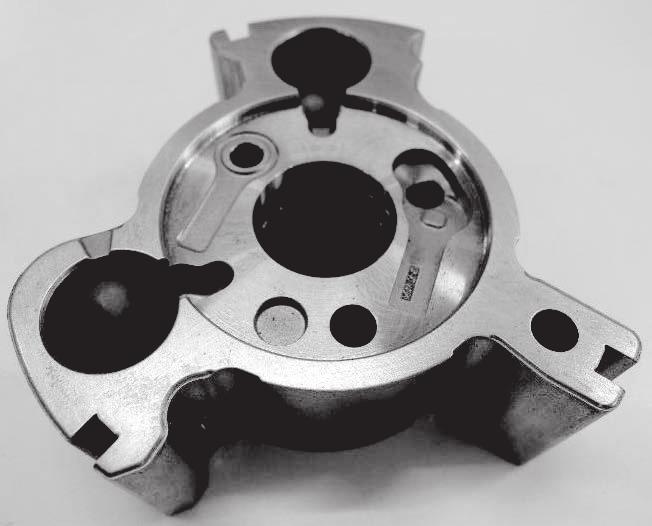
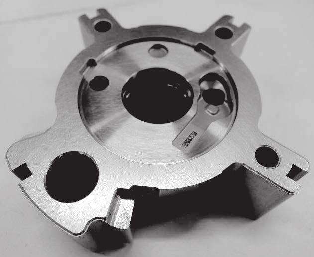

1 INDUSTRIAL MATERIALS High-Quality High-Productivity Manufacturing of Variable Valve Timing Parts by Green Naoto IGARASHI*, Yasunori SONODA, Ryota TAKE, and Hiroaki TERAI In recent years, variable valve timing (VVT) systems have been increasingly used for vehicle engines. The most common VVT is hydraulic systems because they require fewer parts and production costs are lower. However, the rising concern about the environment and demand for improved fuel efficiency have made VVT systems more complicated. We have developed a green machining technique that enables the one-chuck ing of a large number of complicated holes and lateral grooves and established a simple machining line for smart production. For quality assurance, compacts can be traced by 2D codes applied after in-line green machining Keywords: Variable valve timing system, green machining, 2D code 1. Introduction Variable valve timing (VVT)* 1 systems, which are increasing being used for automotive engines, boost fuel economy and reduce exhaust emissions by making the usually fixed opening/closing timing of the intake/exhaust valves controllable. VVT systems are roughly classified into hydraulic and electric systems; at present, hydraulic VVT systems are used more widely since they have fewer parts and are therefore cheaper to manufacture. A hydraulic VVT system is mainly composed of a sprocket, housing, and rotor. Since the shapes of these parts are suitable for forming by sintering, sintered VVT parts have increasingly been used since the 2s. Meanwhile, in response to growing public concern about environmental protection and fuel efficiency, the functions and performance of VVT systems are being improved. Accordingly, the oil passages formed in the systems for hydraulically controlling the component parts are becoming more complex (Photo 1). An example is a VVT system with a built-in oil control valve (OCV). The OCV, which is constructed by additionally cutting oil grooves in the inner diameter surface of the VVT rotor, controls the flow of pressurized oil to minimize the number of necessary parts. Since it is usually impossible to form horizontal holes or inner diameter grooves with molds in a powder metallurgy, these holes and grooves are machined after the parts are sintered. However, deburring sintered parts after machining increases the manufacturing cost and may deteriorate their quality. To solve these problems, we developed a line for producing VVT parts that can achieve high-productivity, high-quality machining of the new VVT rotors shown in Fig. 1. We introduced green machining technology* 2 into the new production line under the concepts of 1) drilling many complexly-arranged holes and cutting inner diameter grooves in green compacts by optimizing the machining conditions and cutting tool geometry, 2) establishing a touchless, stockless, in-line machining of green compacts by synchronizing compacting and green machining, and 3) ensuring the traceability of each product by printing a 2D code* 3 on each green compact. Rotor (intake side) Parts to be ed by green machining Vertical hole :1 Horizontal hole :6 Inclined hole :2 Inner diameter groove :2 Parts to be ed by green machining Vertical hole :1 Horizontal hole :9 Inner diameter groove :2 Rotor (exhaust side) Fig. 1. Products and Their Parts to be Processed by Green Rotor (Intake) Rotor (exhaust) Photo 1. External Appearance of VVT Rotor 48 High-Quality High-Productivity Manufacturing of Variable Valve Timing Parts by Green
2 2. Development of Green Technology The usual flow for making sintered parts is shown in Fig. 2. In the compacting, raw powder composed primarily of iron is poured into a mold and compressed to 5 to 7 MPa on a compacting press to make a green compact. The green compact is merely a packed mass of metal powder. The constituent particles are not yet metallurgically bonded and the shape of the mass is maintained by only the mechanical entanglement force of each particle. The green compact is subsequently conveyed to a sintering and burnt at a temperature of approximately 11 C to 12 C. In this, the powder particles are metallurgically bonded together to become a sintered body or part. After sintering, the part can be ed in the same manner as ingot steel. <Usual flow for making sintered parts> Mixing Compacting Sintering Sizing (Aftertreatment) application examples of green machining include drilling of intersecting holes (2) by utilizing feature 4). Deburring drilled intersecting holes is difficult. On the other hand, the major problems regarding green machining are: 1) the workpiece may chip or suffer cracks since it is a ductile green compact; 2) the parts of the workpiece that can be machined are limited due to low dimensional accuracy and large surface roughness (such parts must be machined after sintering the workpiece); and 3) dust-prevention measures and special-purpose workpiece handling systems are required. (1) The workpiece (green compact) may chip or suffer cracks (during green machining). (1) Suppressing chipping and cracking (a) Enhancing the strength of green compact Increasing the density of green compact Adding binder Optimizing particle size and/or surface geometry Increase in manufacturing cost (b) Optimizing machining conditions Using special-purpose jig (workpiece holding jig) Limitations on the use of green machining <Green machining > Mixing Compacting Note 1 Green machining Sintering The downstream es are the same as those for making conventional sintered parts. Note 1: Green machining is used for ing a part or the wholeof the green compact. Fig. 2. Conventional Parts Sintering Process Flow and Green Process Flow (2) The machined part has low dimensional accuracy and large surface roughness. Separation of particles from machined surface (3) Special-purpose machining is required. A special-purpose green compact handling system and gripper are required. Dust-prevention measures and a chip removing system are required. Items to be considered Optimizing cutting tool geometry and machining conditions (2) Improving dimensional accuracy and machined surface roughness Difficult to improve because of the principle of green machining) Necessary to select workpieces suitable for green machining (3) Developing special-purpose for green machining Green compact handling system that is designed after in-depth consideration of the properties of compacts line that minimizes the risk of damaging workpieces (frequency of contact with workpiece) Production line that ensures the traceability of quality line equipped with dust filter and collector Example of solution We developed a green machining technology useful for shaping parts in the state of green compacts in which the powder particles are not yet metallurgically bonded together, as shown in Fig. 3. Compared with conventional sintered part machining, green machining can the parts at lower shearing stress. The primary features of green machining are that it 1) ensures high productivity, 2) reduces cutting tool wear, 3) allows the use of relatively compact ing due to low cutting resistance, and 4) does not produce burrs since it does not plastically deform metal particles. Some Shearing Usual machining Cutting tool direction Separation of mechanically bonded (entangled) particles Green machining Cutting tool direction Fig. 3. Comparison between Usual and Green Fig. 4. Problems Regarding Green and Example of Solution A possible measure for protecting the workpiece from chipping and cracks (problem 1) is to enhance its strength by increasing the density of the green compact or adding a binder. However, this measure requires higher compacting pressure, which will shorten the mold s service life and increase the raw material cost. Some examples of green machining that prevented the workpieces from chipping by holding them at non-machining parts have been reported. (1),(3),(5) However, the major drawback of this method is that it narrows the range of workpiece geometries that can be ed by green machining. To solve these problems, we developed a VVT parts green machining line that can: 1) prevent green compacts from chipping by optimizing the cutting tool geometry and machining conditions, 2) minimize the risk of deteriorating the quality of machined workpieces by protecting them from chipping and cracking while being handled, and 3) make the quality of products traceable. 2-1 Development of cutting tool for green machining At the initial stage of developing a cutting tool suitable for green machining, we investigated the chipping mechanism of green compacts. To do this, a green compact having a green density of 6.9 g/cm 3 was prepared as shown SEI TECHNICAL REVIEW NUMBER 85 OCTOBER


 Hole-drilling point Excessive radial stress creates tensile stress, increasing the probability of crack generation.")


 Improved drill External view of drill Chipping of drilled Chipping of drilled hole edge on hole edge on entrance side exit side.49 1.55 Fig. 5.")
3 in Table 1. A hole was bored in this green compact with a 4 mm-diameter drill. In this procedure, chipping of the hole circumferential edges on both the drill entrance and exit sides was recorded by a high-speed camera. exit side. For the product to be ed by green machining, horizontal holes must be bored through thin walls as shown in Fig. 6. Drilling these holes was expected to create excessively large radial stress and cause the stressed parts to crack. Table 1. Green Test Conditions Test specimen Cutting tool conditions Description of investigation Test specimen dimensions : mm Material composition : Fe-2.Cu-.8C.8%Lub (EBS) Green density : 6.9 g/cm 3 Drill diameter : 4 mm Point angle : 12 Material : High-speed steel * General-purpose metalworking drill Drill revolution speed : 6 rpm Vf : 16 mm/min Drilling Φ4 through-hole to investigate chipping of circumferential edges on both drill entrance and exit sides Schematic illustration of green machining test Camera Drill Punched end side Camera External appearance of drill used for test Geometry of half-opened hole (drilled at three places) Hole-drilling point Excessive radial stress creates tensile stress, increasing the probability of crack generation. Horizontal hole Cross-sectional view of product Fig. 6. Geomatry of Horizontal Hole to be Drilled by Green and Cross-Sectional View of Product The chipping investigation results are shown in Fig. 5. On the drill entrance side, the circumferential edge of the hole chipped extensively when the outer corner of the drill contacted the workpiece and the chipped edge remained even after the hole was completely bored. We considered that reducing the drill point angle would effectively prevent green compacts from chipping at the circumferential edges of drilled holes on the entrance side. Reducing the point angle will reduce the stock allowance at the drilled hole edge per revolution of the drill, thereby reducing cutting resistance. Chipping of drilled hole edge on entrance side Chipping of drilled hole edge on exit side Separation of large chip Chipping Amount of Chipping:.49 Drill outer corner Amount of Chipping: 1.56 Drill point Cause of chipping Drill moving direction Large cutting resistance of drill outer corner caused chipping. Drill moving direction Thrust force Separation of large chip when drill point exits workpiece Possible chipping prevention measure Reducing cutting resistance by reducing drill outer corner angle Stock allowance Drill moving direction Point angle Radial force Reducing thrust force by reducing drill point angle Feed rate f = mm/rev To overcome such problems, we developed a new, special-purpose cutting tool shown in Fig. 7. The reduced outer corner angle of the new tool minimizes the cutting resistance, thereby eliminating chipping of the workpieces at the circumferential edge of drilled holes on the entrance side. The reduced top angle of the tool optimizes the stress distribution in the thrust and radial directions, thereby preventing the workpieces from chipping at the circumferential edge of drilled holes on the exit side and eliminating crack generation in thin walls. The newly-developed tool dramatically reduced the size of chips at the circumferential edge of the drilled hole on the exit side from 1.6 mm to approximately.3 mm. Type of drill General-purpose drill (for metalworking) Improved drill External view of drill Chipping of drilled Chipping of drilled hole edge on hole edge on entrance side exit side Fig. 5. Chipping of Green Compact, Cause of Chipping, and Possible Chipping Prevention Measures 1 2 Optimization of drill top angle 1) and outer corner angle 2) independently of each other.3.33 At the circumferential edge of the drilled hole on the exit side, a large chip separated from the workpiece when the drill top protruded, and the conspicuously chipped hole edge remained even after the hole was completely bored. We also considered that reducing the drill point angle would disperse the thrust stress in radial directions, thereby effectively preventing the green compact from chipping at the circumferential edges of drilled through-holes on the Fig. 7. Summary of Improved Drill Evaluation Results 2-2 Optimization of green machining conditions To optimize the green machining conditions, we carried out window evaluation using the drill revolution speed plotted on the horizontal axis and the feed rate 5 High-Quality High-Productivity Manufacturing of Variable Valve Timing Parts by Green


. Thrust load (kn) <Example of thrust load measurement> Load (kn) 2 15 1 5-5 2 15 1 5 First hole 17,th hole 36,th hole Load (kn) Feed (F):.26 Feed (F):.")

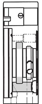
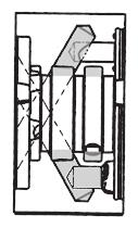
4 plotted on the vertical axis as the parameters as shown in Fig. 8. Based on the evaluation results, we clarified the boundary condition of chipping and determined the machining conditions that assure the required quality of products. Standard feed rate x Green of Inner Diameter Grooves Since the products to be ed by green machining are VVT systems with a built-in OCV, their oil passage is constructed by running a horizontal hole through the inner diameter groove as shown in Fig. 1. When the inner diameter groove is machined after the VVT rotor is sintered, it is difficult to deburr the horizontal hole at its outlet. To eliminate the necessity of deburring, we worked to apply green machining to both the horizontal hole and inner diameter groove. Feed rate Good Revolution speed x.55 Feed rate x 2.7 Revolution speed x.55 Bad Revolution speed x.75 Feed rate x 2 Operational limit of Standard feed rate x 2 Bad Good Standard machining conditions Inclined hole passing through inner diameter groove Intersection (Inclined and vertical holes) Bad Standard revolution speed x.6 Good Revolution speed Inner diameter groove geometry Fig. 8. Process Window Evaluation of Green Conditions Fig. 1. Example of Product Processed by Green With regard to another parameter, which is the state of the drill, a tool dynamometer was used to measure the thrust force imparted to the workpiece during green machining. This made it possible to more quantitatively analyze the wear/deterioration of the tool, and hence quantitatively evaluate the deterioration of the drill with and to determine its service life (Fig. 9). Thrust load (kn) <Example of thrust load measurement> Load (kn) First hole 17,th hole 36,th hole Load (kn) Feed (F):.26 Feed (F): Load (kn) Inner diameter grooves are usually cut on a lathe. However, lathing a workpiece, which is a green compact, may cause cracks in the workpiece since it is strongly gripped by the chuck and is also exposed to centrifugal force created by high-speed turning. To eliminate this risk, we decided to cut the inner diameter groove on a machining center. As an inner diameter groove cutting tool, we developed a special-purpose forming tool (having the same geometry as the groove) that can utilize low cutting resistance, a feature of green machining. The helix and clearance angles of the new tool have been optimized to suppress the generation of stress in the workpieces, thereby protecting them from chipping. The method for inner diameter groove cutting with the new tool is schematically illustrated in Fig. 11. The newly- Step.1 Step.2 Product Special groove cutting tool Driven tool is brought into contact with bore surface. 1, 2, 3, 4, Number of machined workpieces Cutting inner diameter groove by turning workpiece Fig. 9. Number of Machined Workpieces versus Thrust Load Fig. 11. Inner Diameter Groove Cutting Method (Shematic Illustration) SEI TECHNICAL REVIEW NUMBER 85 OCTOBER


 It reduces the risk of deteriorating product quality since it eliminates the need for taking the workpieces in and out of a temporary")

5 developed special-purpose inner diameter cutting tool enables one-chuck machining of many complexly arranged holes and inner diameter grooves. 2-4 Development of green machining line Green machining is expected to increase productivity compared with conventional machining. However, green machining produces a buffer or workpieces in progress between es since the machining cycle is longer than the compacting and sintering cycle s. In practice, an intermittent production system is mainly used for green machining. In this system, green compacts made in the compacting are temporarily placed in stock. After a predetermined number of green compacts are placed in stock, they are conveyed to the green machining and machined. After passing through this, they are again placed in stock. After a predetermined number of machined green compacts are stored, they are conveyed to the sintering. Another system called a stockless production system is also used. This production system consists of two or more pieces of green machining arranged in parallel in order to synchronize the green machining cycle with the production cycle of the compacting press. The features of the two production systems are shown in Table 2. For this study, a stockless production system was selected. Compared with an intermittent production system, the stockless production system increases the investment amount since more pieces of green machining must be installed. However, the stockless production system has advantages: 1) It reduces the risk of deteriorating product quality since it eliminates the need for taking the workpieces in and out of a temporary storage shelf and therefore eliminates their contact with foreign items, 2) it does not use a workpiece storage shelf and therefore reduces the space needed for, and 3) it eliminates the need for storing workpieces in progress and therefore reduces production lead. Production system Intermittent production system Stockless production system Table 2. Features of Production Systems (Green ) Advantage Minimizes the number of pieces of green machinig (Small investment) Reduces the risk of product quality deterioration (Infrequent contact with product) Minimizes space for (Unnecessary to install storage shelves for work-inprogress) Reduces production lead Disadvantage Increases the risk of product quality deterioration (Frequent contact with producct) Requires large space for (installation of storage shelves for work-in-progress) Increases production lead Requires many pieces of green machining (Large investment) Lowers equimpment operation rate (In case of small-quantity production) An outline of the stockless green machining line in which the green machining is operated in synchronization with the compacting press, which we have newly constructed, is shown in Fig. 12. This green machining line consists of a compacting press, a 2D code printer, several pieces of green machining, and a sintering furnace. It is an automated production line in which these devices and are interlinked and operated automatically. Green compacts made by the compacting press are conveyed to the green machining and machined. Subsequently, a laser marker prints a 2D code on each compact. After passing the printing, the green compacts are conveyed to the sintering. This green machining line is a VVT parts production line that has been constructed according to the concept of one-piece flow, no contact with product, stockless, and product traceability through 2D codes. One-piece flow production Touchless production (without work-in-progress) Traceability (2D code) Sizing press (2 ton) Green machining Compacting press (2 ton) Belt-type sintering furnace Laser marker (2D code printing) Fig. 12. Outline of Stockless Production Line in which Green Equipment and Forming Press are Synchronously Operated 2-5 Ensuring product traceability To use such challenging technology as green machining for mass production, it is indispensable to minimize the risk of product quality deterioration by correctly detecting and controlling changing points in manufacturing. In the newly constructed green machining line, a 2D code is printed on each product within the production line immediately after its green compact is machined in order to provide a manufacturing history of the product, as shown in Fig. 13. By reading the 2D code printed on each product, External appearance of product 2D code Production date and information on production are printed. Fig D code (on finished product) 52 High-Quality High-Productivity Manufacturing of Variable Valve Timing Parts by Green
 drilling many complexly-arranged holes and")
 ensuring the traceability of each product by printing a 2D code on each green compact.")


6 it is possible to identify the specific used for machining the product among many pieces of in the production line. 3. Conclusion We have succeeded in constructing a VVT system production line that ensures high productivity and high product quality, under the concepts of: 1) drilling many complexly-arranged holes and cutting inner diameter grooves in green compacts by optimizing machining conditions and cutting tool geometry, 2) establishing touchless, stockless, in-line machining of green compacts by synchronizing the compacting press and machining, and 3) ensuring the traceability of each product by printing a 2D code on each green compact. Contributors The lead author is indicated by an asterisk (*). N. IGARASHI* Assistant General Manager, Development Department, Sumitomo Electric Sintered Alloy, LTD. Y. SONODA Process Engineering Department, Sumitomo Electric Sintered Alloy, LTD. R. TAKE Assistant General Manager, Development Department, Sumitomo Electric Sintered Alloy, LTD. Technical Terms *1 Variable valve timing (VVT) system: A system used in a 4-cycle reciprocating engine to make variable a normally fixed intake/exhaust valve opening/closing timing (valve timing) and valve lift. *2 Green machining: The of machining powdermetallurgically compacted green bodies before they are subjected to solid phase sintering. *3 2D code (2-dimensional code): A two-dimensional way of representing information. Compared with a 1D code (bar code) that represents information in only the transverse direction, the 2D code represents information in both transverse (horizontal) and longitudinal (vertical) directions, thereby making it possible to encode more bits of information and minimize the print area. H. TERAI Plant Manager, Production Department, Sumitomo Electric Sintered Alloy, LTD. References (1) Japan Powder Metallurgy Association AWARD (23) (2) Japan Powder Metallurgy Association AWARD (27) (3) Japan Powder Metallurgy Association AWARD (28) (4) Japan Powder Metallurgy Association AWARD (216) (5) Fine Sinter Co., Ltd., SOKEIZAI Vol.52 No.1 (211) (6) N. Igarashi et al., APMA217 The 4th International Conference on Powder Metallurgy in Asia 138 SEI TECHNICAL REVIEW NUMBER 85 OCTOBER
TOOLS NEWS B218G. Hydro-Clamp Type Valve Finisher HVF. New Product. Series. Drastically shortened time and reduced costs!
 TOOLS NEWS Hydro-Clamp Type Valve Finisher HVF Series B218G New Product Drastically shortened time and reduced costs! Cooperated with Hydro-Clamp Type Valve Finisher HVF Series Greatly Reduced Costs The
DEVELOPMENT OF A NOVEL TOOL FOR SHEET METAL SPINNING OPERATION
 DEVELOPMENT OF A NOVEL TOOL FOR SHEET METAL SPINNING OPERATION Amit Patidar 1, B.A. Modi 2 Mechanical Engineering Department, Institute of Technology, Nirma University, Ahmedabad, India Abstract-- The
Metal Cutting (Machining)
") Metal Cutting (Machining) Metal cutting, commonly called machining, is the removal of unwanted portions from a block of material in the form of chips so as to obtain a finished product of desired size,
Metal Cutting (Machining) Metal cutting, commonly called machining, is the removal of unwanted portions from a block of material in the form of chips so as to obtain a finished product of desired size,
Chapter 23: Machining Processes: Turning and Hole Making
 Manufacturing Engineering Technology in SI Units, 6 th Edition Chapter 23: Machining Processes: Turning and Hole Making Chapter Outline 1. Introduction 2. The Turning Process 3. Lathes and Lathe Operations
Materials Removal Processes (Machining)
") Chapter Six Materials Removal Processes (Machining) 6.1 Theory of Material Removal Processes 6.1.1 Machining Definition Machining is a manufacturing process in which a cutting tool is used to remove excess
Chapter Six Materials Removal Processes (Machining) 6.1 Theory of Material Removal Processes 6.1.1 Machining Definition Machining is a manufacturing process in which a cutting tool is used to remove excess
Module 1. Classification of Metal Removal Processes and Machine tools. Version 2 ME IIT, Kharagpur
 Module 1 Classification of Metal Removal Processes and Machine tools Lesson 2 Basic working principle, configuration, specification and classification of machine tools Instructional Objectives At the end
After continuous casting, the cast products are cut
 Flexible deburring grinding solutions for slabs, blooms and billets for continuous production BRAUN has developed a cast product deburring grinding solution, based on its well-proven HP (high-pressure/high-performance)
Drawing. Fig. 1 Drawing
 Drawing Drawing is a metalworking process which uses tensile forces to stretch metal. It is broken up into two types: sheet metal drawing and wire, bar, and tube drawing. The specific definition for sheet
LANDMARK UNIVERSITY, OMU-ARAN
 LANDMARK UNIVERSITY, OMU-ARAN LECTURE NOTE: DRILLING. COLLEGE: COLLEGE OF SCIENCE AND ENGINEERING DEPARTMENT: MECHANICAL ENGINEERING PROGRAMME: MECHANICAL ENGINEERING ENGR. ALIYU, S.J Course code: MCE
LAPPING FOR MIRROR-LIKE FINISH ON CYLINDRICAL INNER AND END SURFACES USING THE LATHE WITH LINEAR MOTOR
 Journal of Machine Engineering, Vol. 1, No. 1, 1 lapping, linear motor lathe, mirror-like surface, high quality and productivity Aung Lwin MOE 1 Ikuo TANABE Tetsuro IYAMA 3 Fumiaki NASU LAPPING FOR MIRROR-LIKE
Development of Orbital Drilling for the Boeing 787
 Copyright 2008 SAE International 08FAS-0006 Development of Orbital Drilling for the Boeing 787 Eric Whinnem Gary Lipczynski The Boeing Company Ingvar Eriksson Novator AB ABSTRACT The new materials and
Chapter 24 Machining Processes Used to Produce Various Shapes.
 Chapter 24 Machining Processes Used to Produce Various Shapes. 24.1 Introduction In addition to parts with various external or internal round profiles, machining operations can produce many other parts
Development of SUMIBORON BN1000/BN2000 for Hard Turning
 INDUSTRIAL MATERIALS Development of SUMIBORON / for Hard Turning Takashi Harada*, Nozomi TsukiHara, Minori TeraMoTo, satoru kukino and Tomohiro Fukaya With the expanding use of PCBN cutting tools in hard
KTM-16/20 TECHNICAL DATA
 TECHNICAL DATA Table Diameter : 1,600mm Max. Turning Diameter : 2,000mm Max. Turning Height : 1,750mm Table Indexing Degree : 0.001mm CNC Controller : FANUC 18i-TB ** Bed The bed has symmetrical structure
Strip straighteners. Strip spectrum The following coil strips can be processed using our straightening
 STRIP STRAIGHTENERS Strip straighteners SOPREM Precision Straighteners ensure your product quality. Distorted metal components are a thing of the past; today quality products are processed regardless of
Lecture 15. Chapter 23 Machining Processes Used to Produce Round Shapes. Turning
 Lecture 15 Chapter 23 Machining Processes Used to Produce Round Shapes Turning Turning part is rotating while it is being machined Typically performed on a lathe Turning produces straight, conical, curved,
DIRECT METAL LASER SINTERING DESIGN GUIDE
 DIRECT METAL LASER SINTERING DESIGN GUIDE www.nextlinemfg.com TABLE OF CONTENTS Introduction... 2 What is DMLS?... 2 What is Additive Manufacturing?... 2 Typical Component of a DMLS Machine... 2 Typical
Deburring tools GUHRING YOUR WORLD-WIDE PARTNER. EW 100 G Deburring fork EWR 500 Deburring reamer EW 100 S Deburring spiral. Chamfering milling cutter
 EW 100 G Deburring fork EWR 500 Deburring reamer EW 100 S Deburring spiral Chamfering milling cutter Front/back deburrer Ball nose deburrer EW Deburring reamer EWR 500 Deburring tools GURIG YOUR WORLD-WIDE
Manufacturing Sun Cartridge Cavities
 Manufacturing Sun Cartridge Cavities The following Technical Tip discusses a variety of points that should be considered when manufacturing a Sun cavity. Many of the items discussed could be classified
Ahsanullah University of Science and Technology (AUST) Department of Mechanical and Production Engineering
 Department of Mechanical and Production Engineering") Ahsanullah University of Science and Technology (AUST) Department of Mechanical and Production Engineering LABORATORY MANUAL For the students of Department of Mechanical and Production Engineering 1 st
Ahsanullah University of Science and Technology (AUST) Department of Mechanical and Production Engineering LABORATORY MANUAL For the students of Department of Mechanical and Production Engineering 1 st
Drona Gyaan MACHINING-INTRODUCTION
 Drona Gyaan MACHINING-INTRODUCTION Manufacturing is a VALUE ADDITION process by which raw materials or objects of low value due to inadequate material properties, poor or irregular size, shape and finish
Processing and Quality Assurance Equipment
 Processing and Quality Assurance Equipment The machine tool, the wash station, and the coordinate measuring machine (CMM) are the principal processing equipment. These machines provide the essential capability
Roll No. :.. Invigilator s Signature :.. CS/B.Tech (ME)/SEM-5/ME-504/ TECHNOLOGY OF MACHINING. Time Allotted : 3 Hours Full Marks : 70
/SEM-5/ME-504/ TECHNOLOGY OF MACHINING. Time Allotted : 3 Hours Full Marks : 70") Name : Roll No. :.. Invigilator s Signature :.. CS/B.Tech (ME)/SEM-5/ME-504/2009-10 2009 TECHNOLOGY OF MACHINING Time Allotted : 3 Hours Full Marks : 70 The figures in the margin indicate full marks. Candidates
Name : Roll No. :.. Invigilator s Signature :.. CS/B.Tech (ME)/SEM-5/ME-504/2009-10 2009 TECHNOLOGY OF MACHINING Time Allotted : 3 Hours Full Marks : 70 The figures in the margin indicate full marks. Candidates
Product Information Report Maximizing Drill Bit Performance
 Overview Drills perform three functions when making a hole: Forming the chip The drill point digs into the material and pushes up a piece of it. Cutting the chip The cutting lips take the formed chip away
The Ensat self-tapping threaded
 The nsat self-tapping threaded insert nsat is a self-tapping threaded insert with external and internal threads,cutting slots or cutting bores. A continuous process of further development has brought about
The History and Future of Measurement Technology in Sumitomo Electric
 ANALYSIS TECHNOLOGY The History and Future of Measurement Technology in Sumitomo Electric Noritsugu HAMADA This paper looks back on the history of the development of measurement technology that has contributed
Design for machining
 Multiple choice questions Design for machining 1) Which one of the following process is not a machining process? A) Planing B) Boring C) Turning D) Forging 2) The angle made between the rake face of a
Chapter 23 Drilling and Hole Making Processes. Materials Processing. Hole Making Processes. MET Manufacturing Processes
 MET 33800 Manufacturing Processes Chapter 23 Drilling and Hole Making Processes Before you begin: Turn on the sound on your computer. There is audio to accompany this presentation. Materials Processing
Chapter 22 MACHINING OPERATIONS AND MACHINE TOOLS
 Chapter 22 MACHINING OPERATIONS AND MACHINE TOOLS Turning and Related Operations Drilling and Related Operations Milling Machining Centers and Turning Centers Other Machining Operations High Speed Machining
Introduction to Manufacturing Processes
 Introduction to Manufacturing Processes Products and Manufacturing Product Creation Cycle Design Material Selection Process Selection Manufacture Inspection Feedback Typical product cost breakdown Manufacturing
New Item & New Concept Tools Aqua EX Flat Drill
 New Item & New Concept Tools Aqua EX Flat Drill Completely Flat Point Angle! (Point Angle 180 ) Multi-Function Drill Covering Wide Application Range Aqua EX Flat Drill Sharpness & Rigidity at the Same
Metallic Bearings. Oiles 500SP1 P.181 Oiles 500SP5 P.206. Oiles 500SPR P.207 Oiles 500HP P.209 Oiles 500B P.213
 Metallic Bearings Oiles 500SP1 P.181 Oiles 500SP4 P.205 Oiles 500SP5 P.206 Oiles 500SPR P.207 Oiles 500HP P.209 Oiles 500AB P.211 Oiles 500B P.213 Oiles 500F P.217 Oiles 500 Spherical Bearings P.223 Oiles
SINUMERIK live: turning technologies longitudinal turning and plunge-turning. Differences and use with SINUMERIK Operate
 SINUMERIK live: turning technologies longitudinal turning and plunge-turning Differences and use with SINUMERIK Operate siemens.com/cnc4you SINUMERIK live - Application technology explained in an easily
ScienceDirect. Formability of pure titanium sheet in square cup deep drawing
 Available online at www.sciencedirect.com ScienceDirect Procedia Engineering 81 (2014 ) 881 886 11th International Conference on Technology of Plasticity, ICTP 2014, 19-24 October 2014, Nagoya Congress
Development of GE10A Highly-efficient Dry-cut Hobbing Machine Targeting the Automotive Industry
 Development of GE10A Highly-efficient Dry-cut Hobbing Machine Targeting the Automotive Industry 9 KAZUYUKI ISHIZU *1 YOKO HIRONO *2 HIROHISA ICHIHATA *1 MASARU UENO *1 YOSHIHIRO NOSE *3 With the growing
MANUFACTURING TECHNOLOGY
 MANUFACTURING TECHNOLOGY UNIT III THEORY OF METAL CUTTING Broad classification of Engineering Manufacturing Processes. It is extremely difficult to tell the exact number of various manufacturing processes
Abrasive Flow Machining ( AFM ) Semih Sancar Selçuk Ünal Yunus Kocabozdoğan
 Semih Sancar Selçuk Ünal Yunus Kocabozdoğan") Abrasive Flow Machining ( AFM ) Semih Sancar 20622852 Selçuk Ünal 20622976 Yunus Kocabozdoğan 20519809 Goals Getting basic knowledge about AFM Clasification of AFM One-way AFM Two-way AFM Orbital AFM Application
Abrasive Flow Machining ( AFM ) Semih Sancar 20622852 Selçuk Ünal 20622976 Yunus Kocabozdoğan 20519809 Goals Getting basic knowledge about AFM Clasification of AFM One-way AFM Two-way AFM Orbital AFM Application
22 Aug J.T. Hong, S.H. Ahn, H.Y. Jeong, C.Y. Joung Neutron Utilization Technology Division, KAERI
 Development of a drilling machine for the instrumentation of thermocouple in a fuel pellet 22 Aug. 2012 J.T. Hong, S.H. Ahn, H.Y. Jeong, C.Y. Joung Neutron Utilization Technology Division, KAERI Contents
Multi-axis milling/turning system IMTA 320 T2 320 T3. Interaction Milling Turning Application
 Multi-axis milling/turning system IMTA 320 T2 320 T3 Interaction Milling Turning Application T e c h n i c a l D a t a s h e e t The consistent 75 step bed design allows the near rectangular arrangement
Manufacturing Processes (continued)
") Manufacturing (continued) Machining Some other processes Material compatibilities Process (shape) capabilities Manufacturing costs Correct pg 142, question 34i should read Fig 6.18 question 34j should
Manufacturing (continued) Machining Some other processes Material compatibilities Process (shape) capabilities Manufacturing costs Correct pg 142, question 34i should read Fig 6.18 question 34j should
Lecture 3 2: General Purpose Machine Tools: Drilling Machines and Operations Dr. Parviz Kahhal
 Lecture 3 2: General Purpose Machine Tools: Drilling Machines and Dr. Parviz Kahhal Drilling Operation Drilling is a process used extensivelybywhichthroughorblind holes are originated or enlarged in a
An experimental investigation into the orthogonal cutting of unidirectional fibre reinforced plastics
 International Journal of Machine Tools & Manufacture 43 (2003) 1015 1022 An experimental investigation into the orthogonal cutting of unidirectional fibre reinforced plastics X.M. Wang, L.C. Zhang School
An experimental study on the burr formation in drilling of aluminum channels of rectangular section
 5 th International & 26 th All India Manufacturing Technology, Design and Research Conference (AIMTDR 2014) December 12 th 14 th, 2014, IIT Guwahati, Assam, India An experimental study on the burr formation
Contents 1. Cutting and Cutting Tools 2. Processing by End Mills 3. Cutting Action and Phenomena during Cutting
 Basics of End Mills Contents 1. Cutting and Cutting Tools 2. Processing by End Mills 3. Cutting Action and Phenomena during Cutting Contents 1. Cutting and Cutting Tools 2. Processing by End Mills 3. Cutting
Travis Bishop. Submitted to: Dr. John Davis. Date: 3 December Course: ETME 310 Section: 004. Lab Topic: Milling Project (Vise)
") Travis Bishop Submitted to: Dr. John Davis Date: 3 December 2012 Course: ETME 310 Section: 004 Lab Topic: Milling Project (Vise) Introduction: Purpose of Experiment: This experiment was conducted to teach
Travis Bishop Submitted to: Dr. John Davis Date: 3 December 2012 Course: ETME 310 Section: 004 Lab Topic: Milling Project (Vise) Introduction: Purpose of Experiment: This experiment was conducted to teach
Turning and Related Operations
 Turning and Related Operations Turning is widely used for machining external cylindrical and conical surfaces. The workpiece rotates and a longitudinally fed single point cutting tool does the cutting.
Forming - Blanking. Manufacturing Technology II Lecture 6. Prof. Dr.-Ing. Dr.-Ing. E.h. F. Klocke
 Forming - Blanking Manufacturing Technology II Lecture 6 Laboratory for Machine Tools and Production Engineering Chair of Manufacturing Technology Prof. Dr.-Ing. Dr.-Ing. E.h. F. Klocke Seite 1 Content
Design and Research on Die Design of Car Brake Adjuster
 Journal of Computing and Electronic Information Management ISS: 413-1660 Design and Research on Die Design of Car Brake Adjuster Yang Gao a, Dongfang Xu b School of Shandong University of Science and Technology,
MACHINE TOOLS GRINDING MACHINE TOOLS
 MACHINE TOOLS GRINDING MACHINE TOOLS GRINDING MACHINE TOOLS Grinding in generally considered a finishing operation. It removes metal comparatively in smaller volume. The material is removed in the form
INTRODUCTION. HareeshaN G Lecturer Department of aeronautical engg. Classification of manufacturing process
 INTRODUCTION HareeshaN G Lecturer Department of aeronautical engg Classification of manufacturing process 2 Blore 1 Classification of manufacturing process 3 Types of production systems Mass production
Typical Parts Made with These Processes
 Turning Typical Parts Made with These Processes Machine Components Engine Blocks and Heads Parts with Complex Shapes Parts with Close Tolerances Externally and Internally Threaded Parts Products and Parts
The shape of the cone of the twist drills
 The shape of the cone of the twist drills With reference to figure N 1 we can give the following definitions: Fig. N 1- Some characteristic angles of twist drill ε : Helix angle; it is formed by the tangent
Corso di Studi di Fabbricazione
 Corso di Studi di Fabbricazione 3a Richiami dei processi tecnologici di trasformazione FUNDAMENTAL OF METAL FORMING 1 METAL FORMING Large group of manufacturing processes in which plastic deformation is
Research on Casting Edge Grinding Machine of Tracking Type Chang-Chun LI a,*, Nai-Jian CHEN b, Chang-Zhong WU c
 2016 International Conference on Mechanics Design, Manufacturing and Automation (MDM 2016) ISBN: 978-1-60595-354-0 Research on Casting Edge Grinding Machine of Tracking Type Chang-Chun LI a,*, Nai-Jian
STUDY ON DIES FOR WOOD PELLET MACHINES
 STUDY ON DIES FOR WOOD PELLET MACHINES Definition of pellet dies Pellet die can be simply defined as a metal part with holes, either flat or ring-shaped, in which the roller forces raw material under intense
Turning. MECH Dr Ghassan Al-Kindi - Lecture 10 1
 Turning Single point cutting tool removes material from a rotating workpiece to generate a cylinder Performed on a machine tool called a lathe Variations of turning performed on a lathe: Facing Contour
11/15/2009. There are three factors that make up the cutting conditions: cutting speed depth of cut feed rate
 s Geometry & Milling Processes There are three factors that make up the cutting conditions: cutting speed depth of cut feed rate All three of these will be discussed in later lessons What is a cutting
Two Categories of Metal Casting Processes
 Two Categories of Metal Casting Processes 1. Expendable mold processes - mold is sacrificed to remove part Advantage: more complex shapes possible Disadvantage: production rates often limited by time to
Turning and Lathe Basics
 Training Objectives After watching the video and reviewing this printed material, the viewer will gain knowledge and understanding of lathe principles and be able to identify the basic tools and techniques
CHAPTER 1- INTRODUCTION TO MACHINING
 CHAPTER 1- INTRODUCTION TO MACHINING LEARNING OBJECTIVES Introduction to Manufacturing, Manufacturing processes Broad classification of Manufacturing processes Kinematics elements involved in metal cutting
ROOP LAL Unit-6 Lathe (Turning) Mechanical Engineering Department
 Mechanical Engineering Department") Notes: Lathe (Turning) Basic Mechanical Engineering (Part B) 1 Introduction: In previous Lecture 2, we have seen that with the help of forging and casting processes, we can manufacture machine parts of
Notes: Lathe (Turning) Basic Mechanical Engineering (Part B) 1 Introduction: In previous Lecture 2, we have seen that with the help of forging and casting processes, we can manufacture machine parts of
Taking MIM Tooling To the Next Level. Originally published in The American Mold Builder Magazine, February 2014
 Taking MIM Tooling To the Next Level Originally published in The American Mold Builder Magazine, February 2014 1 Metal injection molding (MIM) merges two established technologies, plastic injection molding
AUTOMATED MACHINE TOOLS & CUTTING TOOLS
 CAD/CAM COURSE TOPIC OF DISCUSSION AUTOMATED MACHINE TOOLS & CUTTING TOOLS 1 CNC systems are used in a number of manufacturing processes including machining, forming, and fabrication Forming & fabrication
Experimental investigation of the influence of burnishing tool passes on surface roughness and hardness of brass specimens
 1113 Experimental investigation of the influence of burnishing tool passes on surface roughness and hardness of brass specimens J.N. Malleswara Rao 1*, A. Chenna Kesava Reddy 2 and P. V. Rama Rao 3 1 Department
The Ensat self-tapping threaded insert...
 The nsat self-tapping threaded insert... nsat is a self-tapping threaded insert with external and internal thread, cutting slots or cutting bores. A continuous process of further development has brought
WHAT? WHERE? HOW?
 JIGS WHAT? WHERE? HOW? Introduction Mass production aims at high productivities to reduce unit cost and inter-changeabilites to facilitate easy assembly. Jigs are useful in mass production. They provide
FINITE ELEMENT ANALYSIS OF SINGLE POINT CUTTING TOOL
 FINITE ELEMENT ANALYSIS OF SINGLE POINT CUTTING TOOL Poonam D. Kurekar, S. D. Khamankar 2 M-Tech Student, Mechanical Engineering, Rajiv Gandhi College of Engineering and Research Technology, MH, India
SEMI MAGNETIC ABRASIVE MACHINING
 4 th International Conference on Mechanical Engineering, December 26-28, 21, Dhaka, Bangladesh/pp. V 81-85 SEMI MAGNETIC ABRASIVE MACHINING P. Jayakumar Priyadarshini Engineering College, Vaniyambadi 635751.
Manufacturing Processes - II Prof. A. B. Chattopadhyay Department of Mechanical Engineering Indian Institute of Technology, Kharagpur
 Manufacturing Processes - II Prof. A. B. Chattopadhyay Department of Mechanical Engineering Indian Institute of Technology, Kharagpur Lecture No.25 Estimation of Machining Time Friends, now come to our
TURNING BORING TURNING:
 TURNING BORING TURNING: FACING: Machining external cylindrical and conical surfaces. Work spins and the single cutting tool does the cutting. Done in Lathe. Single point tool, longitudinal feed. Single
Design and Analysis of Press Tool Assembly
 Design and Analysis of Press Tool Assembly Raveendra M.Tech Student ABSTRACT Press working may be defined as a chip less manufacturing process by which various components are made from sheet metal. This
Why gundrills? Dr. Viktor P. Astakhov, Independent Consultant
 Why gundrills? Dr. Viktor P. Astakhov, Independent Consultant Gundrilling, one of the basic and frequently performed material removal processes in the automotive, die and mold, and turbine industries,
Deburring tools GUHRING YOUR WORLDWIDE PARTNER. EW 100 G Deburring fork EWR 500 Deburring reamer
 EW 100 G Deburring fork EWR 500 Deburring reamer Chamfering milling cutter Front/back deburring mill Ball nose deburring mill EW Deburring reamer EWR 500 Deburring tools GURIG YOUR WORLDWIDE PARTER Deburring
GE 101 Final Design Project:
 GE 101 Final Design Project: Clear Point Mechanical Pencil Presented and Submitted on: Monday May 8, 2009 Sarah Fullmer David Montiel Wonseok Oh Ryan Smith Table of Contents Table of Contents... ii List
Module 4 General Purpose Machine Tools. Version 2 ME, IIT Kharagpur
 Module 4 General urpose Machine Tools Lesson 24 Forces developing and acting in machine tools Instructional objectives At the end of this lesson, the students will be able to; (i) Identify the sources
Special reamers. Figure N 1 Reamer with descending cutting edges in carbide (Cerin)
") Special reamers There is a wide category of special reamers, ie non-standard, that are suitable to address particular problems encountered in the finishing holes, both for maintenance of individual pieces
Special reamers There is a wide category of special reamers, ie non-standard, that are suitable to address particular problems encountered in the finishing holes, both for maintenance of individual pieces
EFFECT OF RESIN AND GRAPHITE OF THE BRONZE-BONDED DIAMOND COMPOSITE TOOLS ON THE DRY GRINDING BK7 GLASSES
 16 TH INTERNATIONAL CONFERENCE ON COMPOSITE MATERIALS EFFECT OF RESIN AND GRAPHITE OF THE BRONZE-BONDED DIAMOND COMPOSITE TOOLS ON THE DRY GRINDING BK7 GLASSES Shenq-Yih Luo, Tseng-Yi Wang, Tsung-Han Yu
Module 3 Selection of Manufacturing Processes
 Module 3 Selection of Manufacturing Processes Lecture 4 Design for Sheet Metal Forming Processes Instructional objectives By the end of this lecture, the student will learn the principles of several sheet
Various other types of drilling machines are available for specialized jobs. These may be portable, bench type, multiple spindle, gang, multiple
 Drilling The process of making holes is known as drilling and generally drilling machines are used to produce the holes. Drilling is an extensively used process by which blind or though holes are originated
MANUFACTURING TECHNOLOGY
 MANUFACTURING TECHNOLOGY UNIT IV SURFACE FINISHING PROCESS Grinding Grinding is the most common form of abrasive machining. It is a material cutting process which engages an abrasive tool whose cutting
Cutting with broach. You can find here some notices about broaching operation. Fig.N 1
 Cutting with broach You can find here some notices about broaching operation. Fig.N 1 Amount of cut per tooth This parameter depends on many characteristic of broaching operation like: Material of the
Solid Carbide Tools. Composite Tools. Performance by Design. ISO 9001 Certified Company
 Solid Carbide Tools Composite Tools Performance by Design ISO 9001 Certified Company As one of the world s largest manufacturers of solid carbide rotary cutting tools, SGS Tool Company has pioneered some
Prediction Of Thrust Force And Torque In Drilling On Aluminum 6061-T6 Alloy
 Prediction Of Thrust Force And Torque In Drilling On Aluminum 6061-T6 Alloy P. Kishore Kumar 1 ; Dr. K. Kishore 2 ; Prof. P. Laxminarayana 3 ; Anurag group of Institutions Vasavi College of Engineering
BMM3643 Manufacturing Processes Metal Casting Processes (Sand Casting)
") BMM3643 Manufacturing Processes Metal Casting Processes (Sand Casting) by Dr Mas Ayu Bt Hassan Faculty of Mechanical Engineering masszee@ump.edu.my Chapter Synopsis This chapter will expose students to
BMM3643 Manufacturing Processes Metal Casting Processes (Sand Casting) by Dr Mas Ayu Bt Hassan Faculty of Mechanical Engineering masszee@ump.edu.my Chapter Synopsis This chapter will expose students to
Performance of Diamond Segments in Different Machining Processes
 Materials Science Forum Online: 24-12-15 ISSN: 1662-9752, Vols. 471-472, pp 77-81 doi:1.428/www.scientific.net/msf.471-472.77 Materials Science Forum Vols. *** (24) pp.77-81 24 Trans Tech Publications,
Metal Working Processes
 Metal Working Processes Bachelor of Industrial Technology Management with Honours Semester I Session 2013/2014 CLASSIFICATION OF MANUFACTURING PROCESSES TOPIC OUTLINE What is Sheet Metal? Sheet Metalworking
New type of broaching system
 New type of broaching system The construction of mechanical parts, even simple ones, sometimes involves difficult problems that require, for their resolution, lengthy times or the use of special machines.
Features. High Positive Rake Angle. Multi-Side Grinding. High Speed, High Feed Rate. Economical
 Engraving This is a revolutionary new concept of engraving tools with indexable carbide inserts. They offer you the ability to produce HIGH QUAITY ENGRAVING in most materials. The latest coated carbide
and AM-CAT-COREV(GB)-11/08 High Performance Indexable Insert Systems
-11/08 High Performance Indexable Insert Systems") and AM-CAT-COREV(GB)-11/08 High Performance Indexable Insert Systems Allied Maxcut Engineering Co. Limited AMEC Indexable Drill Range The AMEC range of adjustable indexable carbide drills provides the
and AM-CAT-COREV(GB)-11/08 High Performance Indexable Insert Systems Allied Maxcut Engineering Co. Limited AMEC Indexable Drill Range The AMEC range of adjustable indexable carbide drills provides the
Circular Cold Saws and Systems for every application. Competence in Circular Cold Sawing Technology
 Circular Cold Saws and Systems for every application Competence in Circular Cold Sawing Technology 2 VMS-Range Vertical Circular Cold Saws Manual, semi-automatic and automatic machines Robust and durable.
8029 S 200th St. Kent, WA USA Ph: Fax:
 8029 S 200th St. Kent, WA 98032 USA Ph: 253-872-7050 Fax: 253-395-0230 1 GENERAL INFORMATION Rottler CBN and PCD Inserts are laser marked with our part number on one side. On single sided inserts, the
Drawing of Hexagonal Shapes from Cylindrical Cups
 Dr. Waleed Khalid Jawed Metallurgy & Production Engineering Department, University of Technology /Baghdad Email: Drwaleed555@yahoo.com Sabih Salman Dawood Metallurgy & Production Engineering Department,
Design and Analysis of Spindle for Oil Country Lathe
 Design and Analysis of Spindle for Oil Country Lathe Maikel Raj K 1, Dr. Soma V Chetty 2 P.G. Student, Department of Mechanical Engineering, Kuppam Engineering College, Kuppam, Chittoor, India 1 Principal,
XEBEC AWARD 2008 Best Tip of the Year. How to operate XEBEC Cross-Hole Deburring Tool Alumina Fiber Rod Type with low speed lathes
 AWARD 2008 Best Tip of the Year How to operate Cross-Hole Deburring Alumina Fiber Rod Type with low speed lathes When the spindle can bring up to max 4,000 rpm only, problem is solved by using the air
Features. High Positive Rake Angle. Multi-Side Grinding. High Speed, High Feed Rate. Economical
 Engraving This is a revolutionary new concept of engraving tools with indexable carbide inserts. They offer you the ability to produce HIGH QUAITY ENGRAVING in most materials. The latest coated carbide
STAMPING TECHNOLOGY - CLAMPING RAW PARTS
 simple. gripping. future. 5-Axis 66 Makro Grip Stamping Unit 72 Stamping Unit for the workbench 73 Stamping Unit on trolley 76 Stamping Unit Accessories 77 Stamping Jaws 78 Makro Grip 5-Axis-Vices 82 5-Axis
High Precision CNC Lathe
 High Precision CNC Lathe GN3200 High efficiency through space savings A compact design with a total machine width of 700 mm and a floor space requirement of 1.04 m2 has made it possible to shorten production
Chapter 1 Sand Casting Processes
 Chapter 1 Sand Casting Processes Sand casting is a mold based net shape manufacturing process in which metal parts are molded by pouring molten metal into a cavity. The mold cavity is created by withdrawing
Wire Drawing 7.1 Introduction: stock size
 Wire Drawing 7.1 Introduction: In drawing, the cross section of a long rod or wire is reduced or changed by pulling (hence the term drawing) it through a die called a draw die (Fig. 7.1). Thus, the difference
Workshop Practice TA 102 Lec 6 & 7 :Theory of Metal Cutting. By Prof.A.Chandrashekhar
 Workshop Practice TA 102 Lec 6 & 7 :Theory of Metal Cutting By Prof.A.Chandrashekhar Theory of Metal cutting INTRODUCTION: The process of manufacturing a component by removing the unwanted material using