Link-Belt Screw Conveyors
|
|
|
- Jack Collins
- 6 years ago
- Views:
Transcription

1 Link-Belt Screw Conveyors

2 Table of Contents Introduction Description of Components Components Clamps Conveyor Screws, Helicoid Conveyor Screws, Sectional Covers, Flared Covers, Hip Roof Covers, Semi-Flanged and Flanged End Bearings End Flanges Flighting, Helicoid Flighting, Sectional Hangers Ribbon Conveyor Screws and Flighting Seal Glands Seals, Trough End Shafts, Coupling Shafts, Drive and End Slide Gates Split Flight Couplings Spout, Discharge Spout, Inlet Components (cont'd.) Shrouds Supporting Feet / Saddles Trough End Plates Troughs, Double Flanged Troughs, Flanged and Angle Flanged Troughs, Flared Troughs, Tubular Engineering Capacity Factors Component Groups - Class of Service Component Group Selection Conveyor Designation System Conveyor Screw Deflection Horsepower Requirements Material Classification Selection of Conveyor Size and Speed Screw Feeders Torsional Ratings of Conveyor Screw Parts Layout and Design Layout Information Technical Data


3 Proven Engineered Products Complete Material Handling Solutions Let Syntron Material Handling s knowledgeable team help your business with conveying, feeding, screening, elevating, vibratory flow aids, and mining controls of bulk product. Whether optimizing existing systems or starting from the ground-up on new and customized plants or mines, our dedicated staff will provide you with the most efficient and costeffective solutions. An international leader for innovative solutions, Syntron Material Handling can improve the technology customers are already using. The Link-Belt expertise and equipment have been instrumental in developing some of the world s largest belt conveyors. The Syntron feeders are instrumental to supplying energy sources and material handling efforts across the globe. While management leads the way, the real heartbeat of Syntron Material Handling is a team of employees that have taken idlers, feeders and material handling equipment to new levels of excellence. Many have fine-tuned their skills for more than 20, 30, 40 or even 50 years. Centering our entire operation in Saltillo, MS allows us to maintain the highest Quality Control Standards and on-time deliveries. Our Quality Management System is certified to the ISO 9001:15 standard. We are a charter member of CEMA, and active members of NSSGA, NMA, SME, FEMA, and PMMI. For all your Aggregate needs contact the leader Syntron Material Handling. Moving the World with Link-Belt and Syntron Brands. 1

4 Quality Bulk Handling Equipment that Pays Its Way Link-Belt Screw Conveyors and Screw Feeders Greek mathematician and physicist Archimedes is acknowledged as the inventor of the screw conveyor in B.C., and essentially his design has not changed since then. Syntron Material Handling and Link-Belt added the new and innovative applications which make the Archimedian screw the indispensable tool it is. Plus, Syntron Material Handling's conveyor equipment specialists improved materials and fabrication techniques and added electricity as a power source in the 125 years we nave specialized in manufacturing screw and conveyor components. To the basic Archimedian screw Link-Belt and Syntron Material Handling added conveyor systems and screw feeders, designed them for every conceivable application and manufactured them so well we have become the standard for the industry. Application engineering is a major reason for the industry's wide acceptance of the Link-Belt screw conveyor. Studied attention to detail during this phase eliminates costly installation and operation errors. Close tolerance machining and fabrication in our state-of-the-art manufacturing facility assure equipment quality and performance. Link-Belt Screw Conveyors serve modern industry in a wide variety of ways: Conveying Distributing Collecting Mixing Heating Cooling Elevating Batching Blending Aerating Providing crystallization or coagulant action and more. Our ability to meet your needs with a broad selection of screw conveyors and components is important to you, plus your confidence that the equipment you purchase from Syntron Material Handling will earn its stripes and pay its own way, giving you a good return on your investment. 2 Dimensions subject to change without notice. Certified prints are available upon request.


5 Unmatched versatility. Syntron Material Handling is industry's largest supplier of screw conveyors, feeders and components. You'll find hard-working Link-Belt Screw Conveyors in a broad range of applications, handling everything from alfalfa meal to zinc oxide-over 250 types of materials. And it doesn't matter whether the material is light or heavy, fine or coarse, granular or flaky, hot or cold, wet or dry, sluggish or free-flowing. Syntron Material Handling s Link-Belt Screw Conveyors can handle it effectively and economically. There is a wide selection of Link-Belt Screw Conveyor types to choose from. We make a complete line of screw feeders, conveyor screws, troughs, trough ends, hangers, bearings, shafts, seals and drives. Top Left: Granular feed supplement being conveyed into storage at a poultry processing facility. Center Left: Heilcoid flight conveyor screws perform efficiently on many snow thrower models. Center Right: Twin 12-inch diameter screw conveyors with fully enclosed dust-tight troughs handling pulverized boiler fuel in power generating plant. Bottom: Helicoid screw conveyors are essential components in this flour collecting system located in a large bakery. 3

6 Engineered for every type of service. No one can match our ability to give you the right equipment for your application. Syntron Material Handling engineers pioneered the development of screw conveyors and components for the widest range of materials, purposes and applications. Whether the job involves light-duty service-conveying egg powder, for example-or severe operating conditions-like round-the-clock coal delivery to a power plant-we have the in-depth knowledge and experience to provide just what you need. Link-Belt Screw Conveyors are ruggedly built, accurately manufactured and performance proven. And our unequalled field experience is your assurance of the best in service and recommendations. Clean, compact design saves space, simplifies installation. Link-Belt Screw Conveyors adapt readily to tight quarters and congested locations. No matter how many twists and turns your operation takes, there is a Link-Belt space saving Screw Conveyor to fit. Our conveyors operate effectively in horizontal, vertical or inclined positions. Their compact design permits easy installation. And they're simple to support. If you should need replacement parts, you can count on controlled-tolerance standardized parts that meet CEMA specifications. They're interchangeable for fast, easy assembly, and they don't require special tools. So if space is at a premium, or if you want simple installation and maintenance for better on-line performance, dependable Link-Belt Screw Conveyors are your best choice. Top: Sugar is handled by twin screw feeders and helicoid conveyors in this large bakery. Dropbottom troughs permit easy access and quick cleaning of all parts. Center: Screw conveyor augers are used throughout this combine for gathering, conveying, elevating and distributing the harvest. Bottom Left: Heavy-duty sectional flight conveyor augers installed on boring machine. Bottom Right: Totally enclosed screw conveyors can assure a clean, safe operation. 4 Dimensions subject to change without notice. Certified prints are available upon request.


7 Nearby service when you need it. When you buy from Syntron Material Handling, you can rely on our factorystocked equipment and parts. You keep downtime to a minimum because you get fast turnaround-from order entry to parts delivery at your plant or jobsite. When it comes to bulk material handling, think Syntron Material Handling. Syntron Material Handling has the uncommon ability to solve any screw conveying problem you might face. We ve got the equipment selection experience and the customer service you expect to maintain and operate your facility. Top Right - Over 40 feet of screw conveyors carry malt and rice from storage to mills in this factory. Center Left - Typical installation provides close fitting gates and connections, Center Right - Helicoid screw conveyor delivers 50 tons of coal per hour to boiler room bunkers. Bottom - Granular shell lime distribution system at a large chemical facility. 5
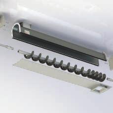
8 Component Description Screw conveyors are one of the oldest and simplest methods for moving bulk materials and consist primarily of a conveyor screw rotating in a stationary trough, Material placed in the trough is moved along its length by rotation of the screw which is supported by hanger bearings. Inlets, outlets, gates and other accessories control the material and its disposition. Screw conveyors are compact, easily adapted to congested locations and can be mounted horizontal, vertical, and in inclined configurations. Their supports are simple and easily installed. These versatile conveyors can be used to control the flow of material in proprocessing operations which depend upon accurate batching... or as a mixer, agitator or stirrer to mix and blend dry or fluid ingredients, provide crystallization or coagulant action, or maintain solutions in suspension. Screw conveyors can be effectively sealed to prevent dust or fumes from escaping or dirt or moisture from entering. They can be jacketed to serve as a dryer or cooler, or furnished in a wide variety of materials to resist corrosion, abrasion or heat. Screw conveyors are used as earth augers to dig post holes or to bore under highways for installation of culverts. They are also used extensively on combines, threshing machines, hay bailers, fodder blowers and many other farm machines. Screw feeders are modified screw conveyors used to control the flow of material at a constant or variable rate from track hoppers, storage hoppers, bins or tanks. They are suitable for handling a wide variety of materials ranging from fines to a combination of fines and lumps. Under many conditions, feeders are also used as a valve. Screw feeders are totally enclosed, compact, simple in design and dust-tight. They are economical to install, operate and maintain. Conveyor Screw The conveyor screw is the rotating portion of a screw conveyor which imparts smooth and positive motion to the bulk material being conveyed. It consists of spiral flighting mounted on a pipe and is made either right or left hand to suit the screw rotation and the desired direction of material travel. Conveyor Screw with Drive Shaft The conveyor drive shaft connects the conveyor screw to the driving unit and transmits rotary motion to the screw. Coupling bolts secure the drive shaft in the conveyor screw. Conveyor Screw with Drive Shaft, End Shaft and Coupling The conveyor drive shaft, end shaft and coupling support the conveyor screw sections and keep them in alignment. The end shaft is located at the end opposite the drive shaft. Couplings are used to connect successive conveyor screw sections when more than one section is necessary to make up the total length of conveyor. The shafts and coupling are secured in the conveyor screws by coupling bolts. 6 Dimensions subject to change without notice. Certified prints are available upon request.


9 component description Trough Ends and Hangers The trough ends support the conveyor drive and end shafts while the hangers support the conveyor couplings, thereby maintaining proper alignment and clearance between the conveyor screw and trough. To provide additional protection for the drive shaft and end shaft bearings, for or against the material being handled, trough end seals are assembled between the flanged blocks and the trough end plates. Conveyor Trough with Inlet Opening and Discharge Spout The trough is the enclosure in which the material is confined and guided in its movement. Trough end flanges preserve the contour of the trough, facilitate assembly of adjoining sections, and insure accurate alignment. Supporting feet at the trough joints or saddles located between the joints, support the intermediate trough sections. Typical Screw Conveyor Complete With Drive A shaft mounted speed reducer makes a simple and compact drive combination. The drive consists of a standard shaft-mounted speed reducer with adapter having a built-in, seal and mounted on a steel plate trough end. A welded steel adjustable motor support bracket is rigidly mounted on the adapter and provides ample clearance over the trough end for easy trough cover removal. Discharge spouts provide outlets for the material and direct its flow to bins or succeeding equipment- With more than one discharge point in a conveyor, selective control may be exercised by means of slide gates, made integral with the discharge spouts. Trough covers with fasteners complete the conveyor enclosure. Material is fed into the conveyor through inlet openings in the cover. 7


10 component description Conveyor Screws Helicoid Flight Conveyor Screws The helicold flight conveyor screw is made of a helix, formed from a flat steel bar or coil strip and mounted on a pipe or shaft. The helix, formed by special rolling equipment to the required diameter, pitch and thickness, is a smooth, continuous one-piece flight. By virtue of its one-piece construction, it possesses superior strength. The absence of laps, rivets or welds on the carrying face of the Flight promotes and maintains cleanliness and reduces wear. The rolling process effects a hardening and smoothing of the flight surface which increases resistance to wear and reduces friction and power consumption. The flight is fastened to the pipe, or shaft, by intermittent or continuous welds and with or without formed steel end lugs. The pipe, of a size carefully selected for adequate torsional strength and resistance to excessive deflection, has internal collars at each end. These collars are permanently inserted and have appropriate inside diameters to accept coupling or end shafts. The assembled helicoid flight conveyor screw is solidly constructed and exceptionally sturdy, and its inherent balance permits operation at high speeds. Its distinctive characteristics contribute to maximum efficiency, durability and economy. Sectional Flight Conveyor Screws Sectional flight conveyor screws are made of individual flights, each blanked from a flat steel plate and formed into a helix. The flights are butt welded together and fastened to the pipe or shaft by intermittent or continuous welds and with or without formed steel end lugs. Sectional flights are formed with regular pitch approximately equal to the diameter. Sectional flight conveyor screws are interchangeable with helicoid flight conveyor screws of the same diameter and shaft size. Sectional flights afford flexibility in choice of diameters, pitches and thicknesses. The Helicoid flight conveyor screw Sectional flight conveyor screw sectional flight conveyor screw is a sturdily constructed assembly, carefully designed to render efficient, economical and lasting service. When desired, sectional flights may be lap welded together, or flights may be continuously welded to the pipe on one or both sides, thus providing exceptionally rugged construction for the most severe conveying applications. Many variations of sectional flight conveyor screws can be furnished to meet specific needs. Some of these are listed on the following pages. Helicold flight conveyor screws are interchangeable with sectional flight conveyor screws of the same diameter and shaft size. Helicold flighting is made with regular pitch approximately equal to the diameter. It can also be furnished with other than regular pitch and in a wide range of diameters, thicknesses and lengths to meet the most exacting requirements. For extremely heavy duty the flighting may be continuously welded to the pipe or shaft on one or both sides. Consult Syntron Material Handling for information on special requirements. Quik-Link Conveyor Screws The Quik-Link conveyor screw Is designed for easy removal from the conveyor trough. Each section of screw is provided with a Quik-Link key located at one end of the pipe. By removing this key, a conveyor screw section and coupling with hanger can be quickly and conveniently disassembled without disturbing other components. Quik-Link conveyor screws are available in both the helicold flight and sectional flight construction. 8 Dimensions subject to change without notice. Certified prints are available upon request.

11 component description Conveyor Screws Cut flight conveyor screws have notches cut in the periphery of either helicoid or sectional flights. These notches supplement the conveying action with a moderate mixing action. They are used for light, fine, granular or flaky materials. Ribbon flight conveyor screws consist of continuous helical flighting formed from steel bar and secured to the pipe by supporting lugs. They are used for conveying sticky, gummy or viscous substances, or where the material tends to stick to flighting at the pipe. Conveyor screws with paddles have paddles spaced at intervals and set to partially oppose the forward flow, to provide a moderate mixing or stirring of materials being conveyed. Paddles are adjustable and may be set at any angle to produce the desired degree of agitation. They are used for light or medium weight, fine, granular or flaky materials. Cut and folded flight conveyor screws provide folded segments which act as lifting vanes to produce a cascading effect. This promotes agitation and aeration, resulting in better mixing. They are used for light or medium weight, fine, granular or flaky materials. Short pitch conveyor screws are of regular construction except that the pitch of the flights is reduced. They are recommended for use in inclined conveyors of 20 degrees slope and over, including vertical conveyors and are extensively use as feeder screws. They retard flushing of materials of a fluid nature. Cut flight conveyor screws with paddles have paddles mounted at intervals and set to counteract the flow of materials, considerably increases the agitation and mixing action produced by the cut flights. Paddle conveyor screws have formed steel blades mounted on rod shanks inserted through the pipe. Conveying action can be controlled by adjusting the angle of the paddles. They are used for mixing, blending or stirring dry or fluid materials. 9
12 component description Conveyor Screws Tapering flight conveyor screws are frequently used as feeder screws for handling friable lumpy material from bins or hoppers and also to draw the material uniformly from the entire length of the feed opening. Stepped diameter conveyor screws consist of flights of different diameters, each with its regular pitch, mounted in tandem on one pipe or shaft. They are frequently used as feeder screws, with the smaller diameter located under bins or hoppers to regulate the flow of material. Stepped pitch conveyor screws are screws with succeeding single or groups of sectional flights increasing in pitch and are used as feeder screws to draw fine free-fiowing materials uniformly from the entire length of the feed opening. Long pitch conveyor screws are occasionally used as agitators for liquids or rapid conveying of very free-flowing materials. Double fiight conveyor screws of regular pitch promote a smooth gentle flow and discharge of certain materials. Double flight short pitch conveyor screws assure more accurate regulation of feed and flow in screw feeders and effectively deter flushing action of fluid materials. 10 Dimensions subject to change without notice. Certified prints are available upon request.

13 component description Conveyor Screws Ribbon Flight Conveyor Screws consist of sectional flights, butt welded together to form a continuous helix. Flights are secured to the pipe by supporting lugs. Variations of diameter, pitch, flight width or thickness can be furnished. Also, these screws can be furnished with either continuous or sectional flights, lap or butt welded together. Ribbon flight conveyor screws are the solution to most conveying problems encountered in the handling of sticky, gummy or viscous materials. The tendency of materials of this nature to adhere and build up at the juncture of solid flight with the pipe is overcome by the open construction of the ribbon flight. Raw sugar, molasses, asphalt, hot tar, sticky feed mixes, and similar products are typical of the many materials successfully handled by ribbon flight conveyor screws. Providing the periphery of ribbon flights with a beveled edge improves operation and reduces power consumption when handling materials which tend to pack or trowel between flights and trough. Consequently, beveled edge ribbon flight conveyor screws are usually subjected to extremely heavy loads, and construction is accordingly heavy and rugged. The ribbon flights are supported on the pipe or shaft by steel lugs, generously proportioned to resist bending. Where the material handled moves virtually en masse, there is but very slight difference in capacity between ribbon and solid flight conveyor screws of the same size. Mixing action without supplementary means of agitation is negligible. Ribbon Flight Conveyor Screw with Paddles To provide moderate mixing or stirring of materials being conveyed, paddles can be furnished, spaced at intervals and set to partially oppose the forward flow. Paddles are adjustable and may be set at any angle to produce the desired degree of agitation. They are used for light or medium weight, fine, granular or flaky materials. Multiple Ribbon Flight Conveyor Screws This type of screw consists of two or more ribbon flights of different diameters and opposite hand, mounted one with in the other on the same pipe or shaft by rigid supporting lugs. Material is moved forward by one flight and backward by the other, thereby including positive and thorough mixing. Abrasion-Resistant Conveyor Screws The particularly severe service encountered when conveying abrasive materials has prompted many attempts to overcome excessive wear on flights. Several successful methods have been developed. Each of these methods offers specific advantages depending on the nature of the material handled and the application. For a careful analysis and recommendation, consult Syntron Material Handling. Ribbon flight conveyor screw Ribbon flight conveyor screw with paddles Hard surfacing by application of a special compound, by arc or torch, to the flight periphery or face, or both, provides an exceptionally hard surface at the points of greatest wear. For severe applications, conveyors with high alumina ceramic tile bonded to the flight periphery or face are also available. Corrosion-Resistant Conveyor Screws Corrosion is manifested in so many different ways that no one choice of material will suit all requirements. To withstand the effects of corrosion encountered in many fields of industry, conveyor screws are fabricated of stainless steel, Monel metal, aluminum, and other materials. Galvanizing and other coating methods have proved effective under mildly corrosive conditions. Vulcanized or bonded rubber covering of the entire conveyor is frequently satisfactory for resistance to extremely corrosive action. Heat-Resistant Conveyor Screws Conveyor screws for high temperature applications are made of many of the available heat-resistant alloys. Several of the stainless steels and other high-chrome alloys are particularly suitable for this service. 11

14 component description Drive Shafts, End Shafts and Couplings The conveyor drive shaft delivers the driving power, and is therefore carefully designed of quality steel of the proper characteristics to provide adequate torque, bending and shear strength, and with closely controlled tolerances for correct bearing clearances. For conveyors of unusual length or for severely heavy loads, alloy steels, heat-treated high carbon steels or 3-bolt connections, are used. Jig-drilled coupling bolt holes and accurately cut keyways contribute to ease of assembly. Conveyor end shaft The conveyor end shaft supports the last section of conveyor screw and is furnished with close tolerances for proper operation in end bearing. Coupling bolt holes are jig drilled for interchangeability and ease of assembly. Conveyor drive shaft Conveyor couplings connect and space adjoining sections of conveyor screw and transmit rotation. Carefully selected steels, with accurate heattreating or hard surfacing when required, insure ample strength and resistance to wear for the kind of service specified. Conveyor coupling For conveyors of unusual length or for severely heavy loads, alloy steels, heattreated high carbon steels or 3-bolt connections are used. Close tolerances on diameters and jig-drilled coupling bolt holes assure interchangeability and ease of assembly. Quik-Link conveyor screw Quik-Link conveyor screws provide an easy means for the quick removal of a conveyor screw section and coupling with hanger without disturbing other components. Regular couplings are used with these screws. Split flight couplings permit installing or removing individual conveyor screws without disturbing adjoining sections. With split flight couplings installed on both sides of each hanger, conveyor screws can be removed without disturbing the hangers. The Link-Belt split flight coupling is sturdily constructed and jig-drilled for coupling bolts. Split flight coupling 12 Dimensions subject to change without notice. Certified prints are available upon request.

15 component description Hangers No. 216 hangers No. 216 hangers have formed steel box frames of superior strength and rigidity and are excellent for heavy service. They are mounted with in the conveyor trough. Mounting holes are slotted parallel with the conveyor to permit adjustment and alignment. These hangers are normally furnished with hard iron, babbitted, bronze, oil impregnated wood or molded fabric bearings, but can also be furnished with special bearings. No. 216F hangers No. 216F hangers are similar in construction to No. 216 hangers except they are designed to mount in, flared trough. No. 220 hangers No. 220 hangers are similar in construction to No. 226 hangers, except they are mounted on top of the trough flanges. Mounting holes are slotted parallel with the conveyor to provide adjustment and alignment. These hangers are normally furnished with hard iron, babbitted, bronze, oil impregnated wood or molded fabric bearings, but can also be furnished with special bearings. No. 226 hangers No. 226 hangers have a rigid, formed-steel box frame with clearance for passage of material in large volume. They are mounted within the conveyor trough. Mounting holes are slotted parallel with the conveyor to permit adjustment and alignment. These hangers are normally furnished with hard iron, babbitted, bronze, oil impregnated wood or molded fabric bearings, but can also be furnished with special bearings. No. 270 ball bearing hangers No. 270 ball bearing hangers have self-aligning ball bearings. The frame is a box-member top-bar with a pipe stem support for the bearing. The bearing is factory adjusted for the proper length from the top-bar and locked with a sealant and a lock nut. The frame is designed for mounting inside the trough and slotted mounting holes parallel to the conveyor permit adjustment and alignment. No. 316 hangers No. 326 hangers No. 316 hangers have formed steel frames of superior strength and rigidity and are excellent for heavy service. They are mounted within the conveyor trough, are self-adjusting and will accommodate operating variations which may exist between the conveyor screw and trough. Mounting holes are slotted parallel with the conveyor to permit adjustment and alignment. These hangers are normally furnished with hard iron, babbitted, bronze, oil impregnated wood or molded fabric bearings, but can also be furnished with special bearings. No. 326 hangers have a rigid, formed steel frame with clearance for passage of material in large volume. They are mounted within the conveyor trough, are self-adjusting and will accommodate operating variations which may exist between the conveyor screw and the trough. Mounting holes are slotted parallel with the conveyor to permit adjustment and alignment. These hangers are normally furnished with hard iron, babbitted, bronze, oil impregnated wood or molded fabric bearings, but can also be furnished with special bearings. 13

16 component description Trough End Plates Trough end plates for either U-trough or flared trough are made of heavy gauge steel plate with the top flanged to support the trough cover. They are furnished with or without supporting feet. Trough end plates can be made of stainless steel or nonferrous metals for corrosive or high temperature applications. They can also be furnished with protective coatings, such as galvanizing. They may be equipped with either sleeve, bolt, or roller bearing flange blocks, or with the addition of a mounting shelf, pillow block bearings. Drive Shaft Trough Ends are of the double ball bearing and double roller bearing types. Each consists of a rigid shaft, operating in double bearings and designed to accommodate both radial and thrust loads. The radial or overhung load is usually a chain drive connected to a power source. Since the bearings will also accept thrust loads in either direction, the need for auxiliary thrusts is eliminated. Drive shaft trough ends with double ball bearings consist of double ball bearing flanged blocks rigidly attached to heavy steel plate trough ends for either U-troughs or flared troughs. The gray iron housings are of one-piece construction and are precision machined for accurate alignment. Effective seals are provided in the flanged blocks to exclude dirt and moisture and retain lubricant. Drive shaft trough ends with double roller bearings consist of heavy duty double roller bearing flanged blocks mounted by means of machined surfaces into extra heavy steel plate trough ends for either U-troughs or flared troughs. The gray iron housings are accurately machined and fitted with roller bearings of high radial and thrust capacity. The blocks have effective seals and are arranged for easy lubrication. Countershaft trough ends are used on screw conveyors where application of right angle drives is necessary due to space limitations, interference of adjoining equipment or for better service and maintenance accessibility. Application of countershaft trough ends permits drive installations alongside, above or below the conveyor and permits using horizontal drives for inclined conveyors. A common drive for two conveyors intersecting at right angles, or a battery of parallel conveyors driven from a common source, can be readily arranged. Trough end with feet Tubular trough end Trough end without feet Flared trough end Trough end with double roller bearing 14 Dimensions subject to change without notice. Certified prints are available upon request.

17 component description Seal Glands, Trough End Seals and Trough End Bearings Seal glands and trough end seals are used to provide additional bearing protection against dust or fumes from within the trough and prevent entrance, along the shaft, of dirt, moisture or lubricant. The trough end seal housings are made of gray iron and are designed for assembly between babbitted, bronze or ball bearing flanged blocks and the trough end plates. They can be provided with lip-type seals for effective protection for or against the materials being handled, with felt seals when handling dusty materials, or with waste packing when handling abrasive materials. Seal glands consist of gray iron, split flanges into which packing materials are compressed against machined steel collars. They are used internally on all trough ends except the outboard bearing type on which they are externally mounted. These seals provide maximum protection for or against the materials being handled. Trough end seal Internal mounting seal gland Trough end bearings Babbitted and bronze bearing flanged blocks are made with one-piece gray iron housings. Babbitted bearing blocks are for general use where loads and speeds are moderate. Bronze bearing blocks are used where heavy bearing pressures, impact loads or temperature conditions are involved. Ball bearing flanged blocks consist of single row, deep groove, self-aligning ball bearings, which are effectively sealed, mounted in one-piece gray iron housings. Spring locking collars with two set screws hold the bearings firmly on the shafts. Ball bearing Flanged block 15

18 component description Troughs The trough not only confines and guides the flow of material, but also serves as the housing in which all operating components are supported and held together in their proper functional relationship. Accuracy in manufacturing and inherent strength to maintain this accuracy are therefore, essential. Link-Belt designs, and manufacturing methods, are constantly being improved to provide these qualities to the fullest extent while at the same time affecting economies in weight and space requirements. Flanged trough - By forming the top flanges integrally with the trough sides from a single steel sheet, adequate strength and rigidity is obtained without superfluous bulk or weight. Steel connecting flanges, securely welded at each end in special welding fixtures to assure square, true ends, facilitate assembly, insure proper alignment and preserve the contour of the trough. Angle Flanged trough - This trough is identical in construction to the flanged trough, except that top flanges are obtained by securely welding structural steel angles to the trough. Flanged trough Flared trough - This trough is of conventional construction except that trough sides are flared outward to afford a wider top opening. This results in improved feed and conveying action with sticky materials or materials which are not entirely free flowing. It is customarily used with ribbon flight conveyor screws. Corrosive or high temperature applications may require the specific qualities that make stainless steel and non-ferrous metals well adapted to these services. In general, any type of trough that can be fabricated of mild steel can also be made of stainless steel or aluminum, brass, bronze, copper, Monel metal, nickel, etc. For resistance to corrosion there are numerous protective coatings that are applied to steel troughs and covers. Galvanizing, tinning, chrome plating, etc., are all effective for certain applications. Vulcanized or bonded rubber coatings resist abrasion and corrosion. Angle flanged trough Flared trough 16 Dimensions subject to change without notice. Certified prints are available upon request.

19 component description Troughs Drop bottom troughs are equipped with a drop bottom usually hinged, held in place by spring clamps of various types for ready access to trough interior, conveyor screws and hangers. This design facilitates quick, thorough, and frequent cleaning of the trough, screw and other parts and is particularly useful to combat infestation and promote sanitation. Channel side troughs are made with separate detachable trough bottoms, bolted or clamped to formed or rolled steel channels. The channels may be of any reasonable length to span widely spaced supports. Trough bottoms are made in lengths up to 12 feet. This trough is occasionally selected for ease of replacement of trough bottoms subject to unusually severe abrasive or corrosive wear. Drop bottom trough Channel side trough Trough Support Supporting feet are of formed steel for use with end flanges and provide a convenient means of aligning and supporting conveyors from floors, and supporting structures. Supporting saddles are used when locatio n of support points does not coincide with the spacing of joint flanges or when troughs with butt strapped connections are used. Support feet Support saddle 17

20 component description Trough Covers Covers are used for protection of operating personnel, dust control or protection for or against the material being handled. When required, protective seals can be furnished between the covers and troughs. Covers are made in three general types: plain, semi-flanged and flanged. Plain covers consist of flat steel sheets and can be furnished with spring clamps, screw clamps or bolts. Plain Cover Semiflanged covers are flanged 30 degrees along the sides and provided with spring clamps attached to the top side of the cover These covers can also be furnished with screw clamps or bolts. Flanged covers have right angle flanges along the sides to provide a stiffer cover for more convenient handling. They are normally attached to the trough with screw clamps or bolts. Semiflanged Cover Hip Roof covers are peaked to form a longitudinal ridge. They are normally furnished for use in outdoor applications because of their ability to shed water. Flanged Cover Shrouds are used in U-trough sections of screw feeders to decrease the clearance between the cover and feeder screw to obtain proper feed regulation. Shroud 18 Dimensions subject to change without notice. Certified prints are available upon request.

21 component description Trough Discharge Spouts and Gates Discharge spouts and gates afford the means for discharging material from the trough and for connection to succeeding equipment to which material is delivered. Gates provide for selective control of multiple spouts. All spouts and gates are of welded steel construction with connecting flanges punched with accurately spaced holes for interchangeability and ease of assembly. Spouts and gates can be fabricated of stainless steel and nonferrous metals. Spouts of special design can be furnished to accommodate unusual conditions. Plain discharge openings are cut in the bottom of the trough at the desired location to provide free discharge of material. They are used for delivering to open or closed storage or similar applications. Discharge Spouts are welded in place when furnished with a complete conveyor. They are furnished in thicknesses proportioned for the size and thickness of trough. Flush end discharge spouts are furnished welded in place on flanged or angle flanged trough. They are furnished in thicknesses proportioned for the size and thickness of the trough. Hand Slide Gates are made to attach to discharge spouts and can be operated from any one of the four sides, provided there is sufficient clearance for the gate in its open position. Rack and Pinion slide gates have cut tooth racks welded to the sideplates and actuated by cut tooth pinions mounted on pinion shafts operated by hand wheels or chain wheels. These are available with either flat slide plates or curved slide plates. Air Operated gates are high quality units designed for low-friction performance in applications requiring frequent gate operation. These gates are built to accept a flange-faced air cylinder and have a roller mounted slide plate operating in a formed steel housing. The cylinder can be furnished with the gate or supplied by the user for field installation. No air piping or controls are provided with these gates. Slide gates, either hand or rack and pinion operated, may be installed in practically all applications for operation either parallel or at right angles to take conveyor axis. Rack and pinion operated gates may be furnished with chain wheels and chains for remote control. Pinion shafts may be extended to accommodate various operating arrangements. Plain discharge opening Discharge Spout Flush end discharge spout Rack and pinion curved slide gate Rack and pinion flat slide gate 19

22 Technical Data The Link-Belt screw conveyor layout, engineering and component selection information in this section is provided to assist you in the selection of the proper conveyor components for your particular material handling requirement. It has been compiled during the many years of experience designing numerous and varied screw conveyor installations, and includes detailed information on all Link-Belt standard screw conveyor components and accessories. The data and formulas presented permit easy selection of the necessary components for handling materials under normal operating conditions by horizontal screw conveyors and screw feeders. Where unusual applications or severe operating conditions are a factor or where there is doubt concerning the correct selection, contact Syntron Material Handling, Tupelo, MS to assist you with additional information. CAUTION: Link-Belt Screw Conveyors and components must be installed, operated and maintained in accordance with Syntron Material Handling Service Instructions. Failure to follow these instructions can result in serious personal injury, property damage or both. Service Instructions are available online at 20 Dimensions subject to change without notice. Certified prints are available upon request.
23 layout information Layout Data Use the conveyor layout on page 22 when selecting components. This layout is based on using regular, or odd length screws and troughs at the tail end of the conveyor and regular length screws and troughs for the drive and intermediate sections. Hangers are located at the trough joints. The drive shafts that provide a nominal clearance between the ends of the conveyor screws and the trough end are designated as Type A shafts. The drive and tall end shafts that are long enough to permit a clearance between the ends of the conveyor screws and the trough ends equal to approximately one-half the hanger bearing length are designated as Type B shafts. Conveyor screws Regular and half length conveyor screws, listed in Table 1 on page 22, should be used to obtain the required total screw length. The face of the screw, which moves the material being conveyed, is free of lugs for unimpeded flow. To maintain this condition, do not reverse rotation without turning the conveyor screws end for end, or conversely, do not turn the conveyor screws end for end without reversing rotation. Conveyor screws for reversible operation can be furnished for specific requirements. Flighting should be omitted over the last discharge opening. Flight ends at hanger locations should be set opposite to each other for continuous flow of material across the hanger space. Selection of hand of screw Refer to Figure A for selection of right or left hand conveyor screws. This drawing indicates the hand of conveyor screw to use when direction of rotation and material travel are known. If the edge of the flight on the near side of the conveyor screw slopes downward to the right, the conveyor screw is right hand, and if it slopes downward to the left, the conveyor screw is left hand. Figure A 21

24 layout information Screw Conveyors Screw conveyors are made with either helicoid or sectional flighting of various thicknesses in a wide range of sizes in both right-hand and left-hand assemblies. The conveyor screws and troughs are made in regular lengths, but can also be furnished in odd lengths to suit requirements. 22 Dimensions subject to change without notice. Certified prints are available upon request.

25 layout information Hangers - Hangers are located between conveyor screw sections. No. 216, 220, 226, 270, 316 and 326 hangers are located at trough joints in Figure B, page 22. All hangers should clear inlet and discharge openings. Trough ends - The drive shaft or end shaft, depending on the direction of material travel, should have a thrust bearing to maintain clearance between the conveyor screws and hangers, and the conveyor screws and trough ends. This prevents excessive wear of operating parts and reduces power consumption. The preferred location for the thrust bearing is at the end of the conveyor, because the conveyor pipes and couplings will then be in tension during operation. Drive shaft trough ends of either the double ball bearing or double roller bearing type will accommodate radial loads and thrust loads in either direction. The radial or overhung load usually consists of a shaft-mounted speed reducer drive or a chain drive connected to a power source. Plain trough ends require auxiliary end thrust provision. Depending upon the direction of the thrust, either the drive or end shaft should have a bronze thrust bearing. Seals - Trough end seals are used for additional protection for or against the material being handled, or to protect and preserve the trough end bearings and shafts when handling abrasive or corrosive materials. Troughs - Regular and half length troughs, listed in Table 1, page 22, should be used to obtain the required total trough length. Whenever possible, supporting feet should be used at the trough joints, otherwise, use saddles as needed. Supporting feet located at the ends of the conveyor will allow removal of the trough ends without disturbing trough alignment. Covers - Covers are made with joints located at the hangers. Protective seals between the troughs and covers are easily applied when No. 216, 226, 270, 316, and 326 hangers are used. Inlet openings in the covers should clear hangers. Drives - Drives should preferably be located at the discharge end of the conveyor in order to keep the conveyor screws and couplings in tension. Assembly Bolts - Table 2 provides a guide to the quantities and sizes of bolts required to assemble a screw conveyor. Bolts are listed for each type of hanger, for each shroud, for each trough joint or trough end, and for 10 foot and 12 foot long sections of bolted cover. Assembly bolts for No. 316 and No. 326 hangers are furnished with hanger assemblies. Screw Conveyors Many bulk materials are handled easily and efficiently in screw conveyors. However, to insure the best possible selection of components, it is recommended that consideration be given to the physical, chemical and handling characteristics of all materials. The essential characteristics include size, flowability and abrasiveness of the materials. Other characteristics, such as contamination, corrosiveness, degradability, fluffiness, etc., may influence the handling and should be given consideration. Consideration should also be given to materials which may assume different characteristics under certain conditions of processing, atmosphere, age or storage. Many of the more common materials are classified in the Material Characteristics Table 4, pages 26 thru 34, and are given as a guide in selecting the proper components. Materials not appearing in the list can be classified by comparison with similar materials or by establishing a classification using the Material Classification Code Chart Table 3, page 25. The delivery of material to a screw conveyor must be at a controlled and fairly uniform rate. ( 1 ) Four bolts ( 2 ) Six bolts ( 3 ) Eight bolts ( 4 ) Ten bolts ( 5 ) Twelve bolts ( 6 ) Fourteen bolts ( 7 ) Sixteen bolts ( 8 ) Eighteen bolts ( 9 ) Twenty bolts ( 10 ) Eight bolts for U-Trough & ten bolts for Flared Trough 23
26 layout information Special applications Occasionally the characteristics of the material being handled are such that other than conventional or regular equipment is required for the purpose, such as: 1. When the materials are extremely hot, the screws and troughs may be made of high temperature alloy metals. 2. If the materials are sticky or viscous, ribbon flight conveyor screws may be the choice. Furthermore, special coatings applied to the screws and troughs may also aid the flow of the material. 3. Extremely abrasive materials may require screws and troughs made of abrasion resistant metals or the screws may be provided with hard surfaced flights. How to select a horizontal screw conveyor Consider the following factors when selecting a horizontal screw conveyor: Kind and character of material being handled, such as: size, flowability, abrasiveness, etc. Weight of material in pounds per cubic foot. Maximum rate at which material is handled in cubic feet per hour. Maximum size of lumps in inches, average size of material and percentage of lumps in total volume. Length of conveyor in feet. 4. When the materials are corrosive, it may be desirable to make the conveyor screws and troughs of stainless steel, Monel metal, nickel, aluminum, etc. 5. If the materials are to be mixed or aerated, a conveyor screw of ribbon flights or cut flights, or one of these combined with paddles may be used to obtain the desired results. 6. Materials which are to be heated or cooled may require jacketed troughs arranged for circulating heating or cooling media. 7. Contaminable materials may require self-lubricated bearings and screw and trough construction which will eliminate pockets, cracks, etc. Such screws and troughs will prevent the accumulation of the material and facilitate easy cleaning. 24 Dimensions subject to change without notice. Certified prints are available upon request.

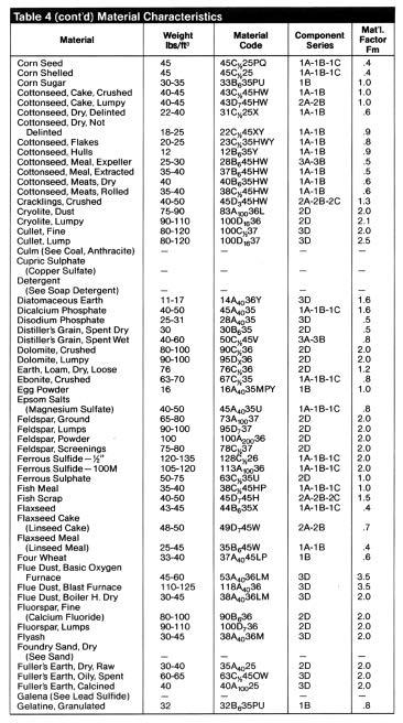
27 material classification Preface to Material Table The Material Characteristics Table 4 lists a wide range of bulk materials that can be handled in screw conveyors. The table shows the first column the range of density that can be experienced in handling that material. The "as conveyed" density is not specifically shown but is often assumed to be at or near the minimum. The next column shows the material code number. This consists of the average density, the usual size designation, the flowability number, the abrasive number followed by those material characteristics which are termed conveyability hazards. The component series column refers to selection of conveyor components as used in Tables 9, 10, 11, & 12 on pages 39 and 40. A very fine 100 mesh material with an average density of 50 lbs. per cubic foot that has average flowability and is moderately abrasive would have a material code 50A If this material was very dusty and mildly corrosive the number would be 50 A LT. The Material Factor is used in the horsepower formula to determine the horsepower to operate a horizontal screw conveyor. The calculation of horsepower is described on page 41. The Material Characteristics Table is a guide only. The material code, and the material factor Fm are based on experience. A specific material sample may have properties that vary from those shown in the table. The range of densities will also vary depending on moisture content as well as its source. 25

28 material classification ( 1 )Consult Syntron Material Handling 26 Dimensions subject to change without notice. Certified prints are available upon request.
Consult Syntron Material")
29 material classification ( 1 )Consult Syntron Material Handling 27

30 material classification ( 1 )Consult Syntron Material Handling 28 Dimensions subject to change without notice. Certified prints are available upon request.
31 material classification 29

32 material classification ( 1 )Consult Syntron Material Handling 30 Dimensions subject to change without notice. Certified prints are available upon request.
Consult Syntron Material")
33 material classification ( 1 )Consult Syntron Material Handling 31

34 material classification 32 Dimensions subject to change without notice. Certified prints are available upon request.
Consult Syntron Material")
35 material classification ( 1 )Consult Syntron Material Handling 33

36 material classification 34 Dimensions subject to change without notice. Certified prints are available upon request.

37 engineering information Selection of Conveyor Size and Speed In order to determine the size and speed of a screw conveyor, It is necessary first to establish the material code number. It will be seen from what follows that this code number controls the cross-sectional loading that should be used. The various cross-sectional loadings shown in the Screw Conveyor Capacity Table 5 are for use with the standard screw conveyor components indicated in the Component Group Selection Guide Table 8 on page 38, and are for the usual screw conveyor applications. The usual screw conveyor applications may be defined as those in industrial use where the conveying operation is controlled with volumetric feeders and where the material is uniformly fed into the conveyor housing and discharged from it. For the calculation of conveyor speeds where special types of screws are used, such as short pitch screws, cut flights, cut and folded flights and ribbon flights, an equivalent required capacity must be used, based on factors in Table 6, page 36. Factor CF, relates to the pitch of the screw. Factor CF 2 relates to the type of the flight. Factor CF3 relates to the use of mixing paddles within the flight pitches. The equivalent capacity then is found by multiplying the required capacity by one or more of the capacity factors that are involved. See Table 6, page 36, for capacity factors. C E = Equiv. Capacity = Required Capacity (CF 1) (CF 2 ) (CF 3 ) cubic feet per hour cubic feet per hour Check lump size limitations before choosing conveyor diameter. See Table 7, page 37. Capacity Table The Capacity Table 5 gives the capacities in cubic feet per hour at one revolution per minute for various sized screw conveyors for four cross-sectional loadings and for various classes of materials as delineated by code numbers. Also shown are capacities in cubic feet per hour at the maximum recommended revolutions per minute. Conveyor Speed For screw conveyors with screws having regular helical flights all of standard pitch, the conveyor speed may be calculated by the formula: Required capacity cubic feet per hour N = Cubic feet per hour at 1 revolution per minute where revolutions per minute of screw, N = but not greater than the maximum recommended speed. *For capacities of inclined screw conveyors, contact Syntron Material Handling. 35
38 engineering information Lump Size Limitations The size of a screw conveyor not only depends on the capacity required, but also on the size and proportion of lumps in the material to be handled. The size of a lump is the maximum dimension it has. A closer definition of the lump size would be the diameter of a ring thru which the lump would pass. However, if a lump has one dimension much longer than its transverse cross-section, the long dimension or length would determine the lump size. The character of the lump also Is involved, Some materials have hard lumps that won't break up in transit through a screw conveyor. In that case provision must be made to handle these lumps. Other materials may have lumps that are fairly hard, but degradable in transit through the screw conveyor, thus really reducing the lump size to be handled. Still other materials have lumps that are easily broken in a screw conveyor and lumps of these materials impose no limitations. Three classes of lump sizes apply as follows: Class 1 A mixture of lumpsand fines in which not more than 10% are lumps ranging from maximum size to one half of the maximum; and 90% are lumps smaller than one half of the maximum size. Class 2 A mixture of lumps and fines in which not more than 25%, are lumps ranging from the maximum size to one half of the maximum; and 75% are lumps smaller than one half of the maximum size. Class 3 A mixture of lumps only in which 95% or more are lumps ranging from maximum size to one half of the maximum size; and 5% or less are lumps less than one tenth of the maximum size. Table 7, page 37 shows the recommended maximum lump size for each customary screw diameter and the three lump classes. The ratio, R, is included to show the average factor used for the normal screw diameters which then may be used as a guide for special screw sizes and constructions. For example: Ratio, R = Radial Clearance, inches Lump Size, inches This ratio applies to such unusual cases as screws 16 inches diameter mounted on 2 inch solid shafts; or 12 inch diameter screws mounted on 6 inch diameter pipes (the large pipe serving to reduce deflection of the screw). The allowable size of a lump in a screw conveyor Is a function of the radial clearance between the outside diameter of the central pipe and the radius of the inside of the screw trough, as well as the proportion of lumps in the mix. The following illustration illustrates this relationship. 36 Dimensions subject to change without notice. Certified prints are available upon request.

39 engineering information To illustrate the choice of screw size from Table 7, say the material is ice with Material Characteristic code number D15, 35 to 45 lbs. per cubic foot and with size distribution as follows: 4"x2," 9% 2"x1," 41% 1"x 3 /8," 22% minus 3 /8," 28%. This lump size distribution falls under Class 1. From Table 7, the ratio R is 1.75 and the radial clearance (4) (1.75) or 7 inches. This calls for an 18 inch diameter screw. Component Groups To facilitate the selection of proper specifications for a screw conveyor for a particular duty, screw conveyors are broken down into three Component Groups. These groups relate both to the Material Classification Code and also to screw, pipe size, type of bearings and trough thickness. If the material to be conveyed is not listed in Table 4, pages 26 thru 34, then its Classification code may be determined from Table 3, page 25. Table 8 is a guide to the proper selection of the appropriate Component Group. It will be observed that in addition to the flow characteristics of a material, consideration must be given to the material size, its abrasiveness and its corrosiveness as these determine construction details. For example, if the material has suitable flow characteristics, is of a classification Code Size B, has an abrasive number of 5 and is non-corrosive, the Component Group Number is 1. If babbitted or bronze bearings, 1A; or for bali bearings, 1C. It will be noted that if the material is at all corrosive, ball bearings are not recommended. Having made the Component Group selection, refer to Tables 9, 10 and 11, pages 39 and 40, which give the specifications of the various sizes of conveyor screws. The tabulated screw numbers in this table refer to CEMA Standard No. 300 on Screw Conveyors. This standard gives complete data on the screws such as the length of standard sections, minimum edge thickness of screw flight, bushing data, bolt size, bolt spacing, etc. 37
 Ball bearings are not usually recommended for conveyors handling materials partly or wholly finely ground.")
40 engineering information ( 1 ) For very corrosive conditions (codes 6S or 7S) lighter gauge special anti-corrosion materials may be used. ( 2 ) Ball bearings are not usually recommended for conveyors handling materials partly or wholly finely ground. (Code A) ( 3 ) Any abrasive material which is flammable, corrosive, or which may contain explosive dust, consult manufacturer for bearing recommendations, Conveyor screw speeds must be considered when using hard iron bearings on hardened coupling shafts in order to minimize wear and to reduce the squealing noise of dry metal on metal. The following formula gives maximum recommended operating speed: N = 120 Shaft diameter in inches N = Maximum operating rpm of screw For bearing types A, B and C listed above, the shafting used for the couplings is AISI C1018 standard cold rolled steel or equal. For hard iron bearings, the shafting for the couplings is usually medium carbon steel AISI 1045 and surface hardened. Suitably hardened alloy shafting also may where 38 Dimensions subject to change without notice. Certified prints are available upon request.

41 engineering information Component Groups 39
42 engineering information 40 Dimensions subject to change without notice. Certified prints are available upon request.

43 engineering information Horsepower Requirements, Horizontal Screw Conveyors The horsepower required to operate a horizontal screw conveyor is based on proper installation, uniform and regular feed rate to the conveyor and other design criteria as determined in this catalog. The following factors determine the horsepower requirement of a screw conveyor operating under the foregoing conditions. C E = Equivalent capacity in cubic feet per hour. e = Drive efficiency. F b = Hanger bearing factor. See Table13. Fd = Conveyor diameter factor See Table 14, page 42. F m = Material factor. See Table 4, pages 26 thru 34. F o = Overload factor See Figure D, Page 42. L = Total length of conveyor, feet. N = Operating speed, rpm. W = Apparent density of the material AS CONVEYED, lbs. per cubic foot. See Table 4, page 26 thru 34. The horsepower requirement is the total of the horsepower to overcome conveyor friction (HPf) and the horsepower to transport the material at the specified rate (HPm) multiplied by the overload factor Fo and divided by the total drive efficiency e, or: HPf = LN F d F b 1,000,000 horsepower formula, a 5 hp motor must be used and all power transmitting elements must be capable of safely handling the full 5 horsepower. Problem Material Vermiculate Ore Weight lbs/ft 3 Capacity ft 3 /hr Max. Lump " Length of Conveyor '-0" Refer to Table 4, pages 26 thru 34. The material class is 80D The component series is 2D and the material factor Fm is 1.0 Refer to Table 5, page 35, and select a 16" diameter 30% loading capable of 1400 ft 3 /hr at a max. speed of 45 rpm. Capacity of unit is 31.2 ft 3 /hr at 1 rpm. N = 120 = 40 rpm; 39 rpm satisfactory 3 LN F d F b 31 x 39 x 106 x 4.4 HP f = = = ,000,000 1,000,000 C E LW F m 1200 x 31 x 85 x 1.0 HP m = = = ,000,000 1,000,000 (HP f + HP m )x F o ( )1.21 MHP = = = 5.28 use 7 1 / 2 e.85 or use Figure E, page 42, HP1 = = 3.72 Use 7 1/2 hp. Required speed = Torque = HP x 63,025 T = 7.5 x 63,025 T = 12,120 in. lb. N 39 Table 15, page 43, indicates a 2-bolt connection is rated 16,400 in. lb =38.46 call 39 rpm. Table 8, page 38, indicates a hard iron hanger bearing. Component series 2D indicates Heavy Service Table 10, page H614 helicoid screw flight - 3" diameter shaft 3 /16 "trough and 14 ga. cover. Max. speed for 3" diameter shaft using hard iron bearings. HPm = C E LWF m 1,000,000 (HP f + HP m ) F o Motor HP = e or use Figure E, page 42, where HPt = (HPf + H Pm). It is generally accepted practice that all power transmitting elements of a screw conveyor be sized and selected to handle safely the full load motor torque. If, for example, a screw conveyor requires 3.5 horsepower as determined by the 41
44 engineering information Factor F 0 and A Drive Efficiency of 85% Are included. Figure E 42 Dimensions subject to change without notice. Certified prints are available upon request.

45 engineering information Torsional Ratings of Conveyor Screw Parts Screw conveyors are limited in overall length by the amount of torque that can be safely transmitted through the pipes and couplings. Table 15 combines the various torsional ratings of bolts, couplings and pipes so that it is easy to compare the torsional ratings of all the stressed parts of standard conveyor screws. The table conforms to the CEMA Screw Conveyor Standard No The torsional values are confined to the sizes listed in that standard. The lowest torsional rating figure for any given size of coupling will be the one that governs how much horsepower may be safely transmitted. For example, using standard unhardened two bolt coupling shafts, the limiting torsional length of each part is indicated in Table 15. Thus it can be seen that the shaft itself is the limiting factor on 1," 1 1 /2," and 2" couplings. The bolts in shear are the limiting factors on the 2 7 /16," coupling and on the 3" coupling used in conjunction with 4" pipe. The bolts in bearing are the limiting factors for the 3" coupling used in conjunction with 3 1 /2" pipe, and for the 3 /16" coupling x HP Torque, T Q = rpm If coupling bolt shear is the limiting torsional rating, high strength bolts may be substituted. When using high strength bolts the limiting factor will, in all cases, be either the coupling shaft or the bearing value, and both must be checked. Screw Conveyor End Thrust Most screw conveyors can be designed with little thought given to thrust as the thrust force in an ordinary screw conveyor is moderate and commonly used screw conveyor drives will accommodate thrust in either direction. However, in screw feeders with long inlet openings and in screws used to compress material (either by design or by accident when discharge openings are plugged) thrust forces can be very severe. Severe thrust forces can strip the flights from the pipe, stall the drive, result in sheared coupling bolts or fractured couplings and shaft. The direction of thrust in a screw conveyor or feeder is opposite to the direction of flow of the product. It is preferred to accommodate the thrust at the discharge end as this results in the line of screws and couplings being in tension. The most common drives in use today are the so-called screw conveyor drives that are adaptations of shaft mounted reducers. These include drive shafts that are secured in the reducer so as to take thrust in either direction and transfer the thrust force to one of the hollow shaft bearings of the reducer. 43
46 engineering information CONVEYOR SCREW DEFLECTION Deflections of conveyor screws of standard lengths not usually a problem. However, if longer than standard sections of screw are to be used, without intermediate hanger bearings, care should be taken to prevent the screw flights from contacting the trough because of excessive deflection. The nomograph on page 45 indicates the deflection of standard helicold conveyor screw sections on schedule 40 and schedule 80 pipe, for various lengths of screw sections. The schedule 80 pipe may be needed for large torques. Applications of screw conveyors in which the deflection of the screw exceeds 0.25 inches should be referred to the screw conveyor manufacturer for recommendations. (In some applications, a deflection of even less than 0.25 inches could be critical and should be referred to the manufacturer.) Very often the problem can be solved by using a conveyor screw section with a larger diameter pipe. It will be noted from the nomograph that the use of a schedule 80 pipe reduces the deflection very little, hence it isn't practical to reduce deflections by using heavier pipe. Larger diameter pipe should be used. Example NO. 1 Determine the deflection of a 12H512 conveyor screw section mounted on a schedule 40 pipe, with an overall unsupported length of 18 feet. From the nomographic chart, Figure 3.6, the deflection is greater than 0.25 inch, and therefore indicates that the problem should be referred to the screw conveyor manufacturer for solution. When the flights of the screw are mounted on something other than Schedule 40 or Schedule 80 steel pipe, such as mechanically drawn tubing or solid shafting or steel or other metals, the deflection at mid span may be calculated from the following formula: 5 WL 3 s= 384 El where: s = deflection at mid span, inches W = total weight of screw, lbs. L = Length of screw between bearings, inches E = modulus of elasticity for steel I = moment of inertia of hollow or solid shaft section. Example NO. 2 Determine deflection of a 12H614 conveyor screw 20 ft. long. According to manufacturers' catalogues it has a weight of 228 lbs. for an 11-9 long section and has helicoid flighting mounted on 3 1 /2" schedule 40 iron pipe size. W = 228 x 20 = 388 lbs L = 20 X ", L 3 = 13.8 X 10 6 E = 30 X 106 I = 4.79 (3 1 /2" schedule 40 pipe) (5) (388) (13-8) (10) 6 s = = 0.48 (384) (30) (10) 6 (4.79) The 0.48 inch deflection is greater than the 0.25 inch normally allowable deflection. Therefore, a larger diameter pipe or other section having a higher moment of inertia may be tried. The nomograph on Page 45 will solve some examples of conveyors longer than usual or longer than standard lengths. 44 Dimensions subject to change without notice. Certified prints are available upon request.
47 45

48 engineering information Screw Feeders This section relates to screw feeders that are used to control the rate of flow of a bulk material from a bin or hopper. This is limited to the handling of bulk free flowing materials less than 1 /8" in size and which are classified as abrasive 5 or 6 as shown in Table 3, page 25. In screw feeders, the inlet portion of the trough is made to be flooded with the material and by means of a shroud in the trough, or by the use of a tubular trough, only a controlled amount is carried to the discharge. The screws in the feeder are arranged in several different ways, depending upon circumstances. For relatively small inlet openings, the screw often has a standard diameter and pitch. Frequently, however the screw is tapered in diameter with its smallest diameter at the extreme feed end. Screws also may be made with a constant standard diameter and a variable pitch, the pitch growing larger from the extreme feed end. The purpose of the tapered diameter or variable pitch screw is to obtain an even flow from all areas of the feed opening. The capacity of tapered screws or variable pitch screws is determined by the diameter and pitch at the downstream end of the inlet opening. Several factors should be established before selecting a screw feeder, these being: A. Kind and character of material being handled. B. Density of material as conveyed, lbs/ft 3. C. Maximum rate at which material is to be handled, ft 3 /hr. D. Size consist or screen size analysis. E. Overall length of feeder, or feeder with extended conveyor, feet. F. Width and length of inlet opening. Single screw feeders are most commonly used. However, if the inlet opening is very wide, multiple screw feeders are more practical. Single Screw Feeders The single screw feeder may be a separate unit, or it may be extended by sections of normal screw conveyor to any practical length. The procedure by which to choose a single screw feeder is as follows: Refer to Material Classification Code, Table 3, page 25, and the Material Characteristics, Table 4, pages 26 thru 34. Determine the material code class and density from Table 4. Capacity and Speed From Table 16, under the column captioned at maximum rpm, find the capacity which equals or exceeds the desired feeder capacity. Then find from that the feeder diameter and capacity at one rpm or C,. Divide the required feeder capacity by C, to obtain the required speed in rpm. C N= Ct where: N = Speed of feeder in rpm. C = Required capacity of feeder, ft 3 /hr. C1 = Capacity at one rpm, ft 3 /hr. This maximum rpm is not absolute but has been selected as general recommended practice. Experience with a particular set of conditions, or application, may establish slightly different design limitations. Many factors including bin or hopper design, a subject not covered here, will significantly affect screw feeder performance. Single Screw Feeder Arrangement The arrangement and dimensional data for single screw feeders are shown in Figure F, page 47, and Table 16. Extension Conveyor The arrangement of an extension conveyor, directly connected to a single screw feeder, is shown in Figure G, page 47. Obviously the extension conveyor must operate at the same rpm as the feeder. The size of the extension conveyor may be obtained by referring to Table 5, page 35. For the code class of the material to be handled find a screw diameter which will give an equal or greater capacity in cubic feet per hour at one rpm than the C, capacity of the screw feeder used in the formula to determine the feeder speed. The degree of trough loading corresponding to the code class of material to be handled and its abrasiveness, must not be exceeded. ( 1 )Dimensions are typical and approximate. Actual dimensions should be certified for installation purposes. ( 2 )Based on 100% of theoretical capacity with standard pitch and screw pipe. For nonstandard pitch or pipe size consult screw conveyor manufacturer. ( 3 )Maximum in regular construction. Larger inlet openings require engineering consideration not covered here. ( 4 )The length C is equal to two standard pitches. 46 Dimensions subject to change without notice. Certified prints are available upon request.
49 engineering information Single Screw Feeder Figure F Single Screw Feeder With Extention Conveyor Figure G Power Required The calculation of the required horsepower to operate screw feeders is very similar to that involved for standard screw conveyors. Essentially, the calculation involves the addition of two horsepowers, one for empty feeder friction, and the other the material friction. Horsepower for Single Screw Feeder: (HPa + HPb)Fo HP = e Horsepower for Single Screw Feeder with Extension Conveyor: 1(HRa + HPb + HP1 + HPm) Fo HP = e Where: Empty Feeder Friction Power L1 N Fd Fb HPa = 1,000,000 Feeder Material Friction Power C W Lf Fm HPb = 1,000,000 and Empty Extension Conveyor Friction Power L N Fd Fb HPf = 1,000,000 Extension Conveyor Material Friction Power C W L Fm HPm = 1,000,000 and the nomenclature used is defined: C = Capacity in ft 3 /hr. W = Apparent density of materials as conveyed, lbs/ft 3 L = Length of extension conveyor, feet. Lf = Equivalent length of feeder, feet. See Table 17, page 48, for method of arriving at values of L1. L l = Length of feeder, feet, as shown in Figures F and G. N = Speed of screw rotation, rpm. Fb = Hanger bearing factor, Table 13, page 41. Fd = Conveyor diameter factor, Table 14, page 42. Fm = Material factor, Table 4, pages 26 thru 34. Fo = Overload factor, Figure 14, page 42. e = Efficiency of the drive selected. 47
 per hour = 800 cubic feet per hour 10 feet 40inches long, 10 inches wide Required is an")
50 engineering information Example of Single Screw Feeder Selection Problem: Select a single screw feeder without extension conveyor for the following conditions Material to be handled Weight per cubic foot Capacity Length of feeder, L1 Inlet opening Salt cake, dry, pulverized lbs per ft 3 26 tons (2000lb) per hour = 800 cubic feet per hour 10 feet 40inches long, 10 inches wide Required is an even rate of flow along the whole inlet opening. Solution: (a) From table 4, pages 26 thru 34, salt cake is code classified at 75 B 6 36 TU has a component group designation of 3-D and a material factor (Fm,) of 1.7. (b) From Table 13, page 41, for a Component Group D, the hanger bearing factor, Fb = 1.0. Since this example does not have a hanger, Fb = 1.0. Use the appropriate factor when a hanger bearing or a tail bearing that utilizes a hanger insert type bearing is used. (c) To be prudent, for capacity calculations use the lowest apparent density, 65 lbs/ft 3.Then the volume for 26 tons per hour is (26) (2000) = ft 3 /hr required feed rate. (d) Referring to Table 16, page 46, a 9-inch diameter single screw feeder will handle 1202 ft 3 /hr at a maximum of 65 rpm and C 1 =18.5 at one rpm. Using the formula for speed. N = C = 800 = 43.2 rpm C f 18.5 (e) From Table 17, the equivalent length of the feeder is L 1 + B + C in which 6 12 B 40 L 1 = 10, = or 6.7, and 6 6 C (18) = = L f = feet (f) From Table 14, page 42, the conveyor diameter factor Fd = 31. (g) Again to be prudent, for power calculations it is well to use the largest apparent density for W, so W = 85 lbs/ft 3. L 1 N F d F b (h) HPa = = 1,000,000 (10) (43.2) (31) (1.0) =.013 HP 1,000,000 C W L f F m (i) HP b = = 1,000,000 (800) (85) (21.5) (1.7) = 2.10 HP 1,000,000 (j) Referring to Figure D, page 42, the factor F o depends upon the sum of the horsepower for friction of the empty conveyor (feeder in the example) and the horsepower of (HPa + HPb) Fo HP = = e ( ) (1.57) = 3.90 HP.085 material friction. In this example this sum is = HP and Fo = (k) Then assuming a drive efficiency (expressed decimally) of 0.85, Or use Figure E, page 42 HPt = (HPa + HPb) = MHP = 5 (1) Use a 5 hp electric motor with speed reduction to 43.2 rpm. The theoretical estimated power requirements calculated in the foregoing example conceivably could be exceeded to the extent that the full 5 horsepower of the motor would be used. Therefore, all components of the power train, the feeder shaft, the screw pipe shaft and the screw itself should be capable of withstanding-at the speeds involved for each-the torsion force or torque of full 5 horsepower. See Table 15, page 43 for torsional capacities of screw conveyor components. Effect of Material Loads on Screw In many cases, where screw feeders are mounted at the bottoms of bins or hoppers, the screw has to perform its function under heavy loads of material above the bin opening or feeder inlet. Under certain conditions and with certain materials the start-up torque can be very high, resulting in bigger drives and heavier feeder components. An alternative solution is the use of multiple screw feeders. Multiple screw feeders may consist of twin, triple, or quadruple screws, side by side to feed materials from very wide inlet openings. 48 Dimensions subject to change without notice. Certified prints are available upon request.
51 engineering information Conveyor Designation System Screw diameter & pitch 12- = Full Pitch 12-8 = 2 /3 pitch 12-6 = 1 /2 pitch 12-4 = 1 /3 pitch Coupling diameter 3 = 1 1 /2" 4 = 2" 5 = 2 7 /16" 6 = 3" 7 = 3 7 /16" E = Standard Length EF = Righting F = Flight Type Conveyor H = Helicoid HR = Helicold ribbon HS = Hellcoid stainless HSR = Helicold stainless ribbon S = Sectional SIR = Sectional ribbon SS = Sectional stainless SSR = Sectional stainless ribbon NOTE: Q prefix on all above types for Quik-Link. Flight thickness at outer edge 1 /64" increments 49

52 component selection Helicoid Flight Conveyor Screw Helicold Flight Conveyor Screws are made of a continuous one-piece helix fastened to a pipe with spaced intermittent welds. Steel lugs are welded to pipe and flight at both ends, except on 4-inch size. 50 Dimensions subject to change without notice. Certified prints are available upon request.

53 component selection Helicoid Flight Helicold Flighting is manufactured in a continuous one-piece helix of the desired diameter, pitch and thickness. The helicold flight is tapered in cross section, with the thickness at the inner edge about twice the thickness at the outer edge, 51

54 component selection Sectional Flight Conveyor Screws consist of individual flights formed into a helix. then butt welded together and fastened to a pipe or shaft with spaced intermittent welds, Steel lugs are welded to pipe and flight at both ends, except on regular sectional flight screw sizes larger than 16-inch diameter. Both ends of the pipe have permanent internal collars with inside diameters to accept couplings, drive shafts or end shafts. Sectional Flight Conveyor Screw Sectional Flight 52 Dimensions subject to change without notice. Certified prints are available upon request.

55 component selection 53

56 component selection Sectional Flights are individual flights formed into a spiral or helix of the desired diameter and pitch, butt welded together to form a continuous conveyor screw. 54 Dimensions subject to change without notice. Certified prints are available upon request.

57 component selection 55

58 component selection Ribbon flight conveyor screws consist of sectional flights, butt welded together to form a continuous helix. Flights are secured to the pipe by supporting lugs. Both ends of the pipe have permanent internal collars with inside diameters to accept couplings, drive shafts and end shafts. They are used for conveying sticky, gummy or viscous substances, or where the material tends to adhere to flighting at the pipe. Stainless steel ribbon flight conveyor screws can be furnished. 56 Dimensions subject to change without notice. Certified prints are available upon request.

59 component selection Type 1 Paddles consist of formed steel blades mounted on bolt or rod shanks which are inserted through regular conveyor screw pipe. They are normally mounted at 120 degree intervals spacing, three paddles per pitch. Paddle at each end of conveyor may be inserted through bolt hole in place of regular coupling bolt. Paddle blades may be set at any angle to produce the desired degree of agitation. Paddle conveyor screws are used for mixing, blending or stirring dry or fluid materials. Drive shafts deliver the driving power, and are designed to provide adequate torque, bending and shear strength, and correct bearing clearances. For extra heavy loads, high carbon steel or heat-treated alloy steel shafts are used. Jig-drilled coupling bolt holes and accurately cut keyseats contribute to ease of assembly. End shafts serve only as support for the last section of conveyor screw and are furnished of cold-finished steel. 57

60 component selection 58 Dimensions subject to change without notice. Certified prints are available upon request.

61 component selection 59
62 component selection End Lugs are die-formed steel plates welded to both ends of helicold flighting and to the pipe to strengthen the end of flighting. Split Flight Couplings permit installing or removing individual conveyor screws without disturbing adjoining sections. With split flight couplings installed on both sides of each hanger, conveyor screws can be removed without disturbing the hangers. The split flight coupling is sturdily constructed and jig drilled for coupling bolts. 60 Dimensions subject to change without notice. Certified prints are available upon request.

63 component selection Split Flight Coupling Shafts are used to transmit rotation and to position accurately and support the split flight couplings. 61
64 component selection No. 270 Hangers have formed steel frames and self-aligning ball bearings which reduce power consumption and noise levels. 62 Dimensions subject to change without notice. Certified prints are available upon request.

65 component selection No. 216 Hangers have formed steel frames of superior strength and rigidty and are excellent for heavy service. These hangers are normally furnished with hard iron, babbitted: bronze, oil impregnated wood or molded fabric bearinqs, but can also be furnished with special bearings. 63

66 component selection No. 226 Hangers have a rigid formed steel frame with clearance for passage of material in large volume. These hangers are normally furnished wit h hard iron, babbitted, bronze, oil impregnated wood or molded fabric bearings, but can also be furnished with special bearings. Stainless steel frames can be furnished. 64 Dimensions subject to change without notice. Certified prints are available upon request.
67 component selection No. 316 Hangers are similar in construction to No. 216 hangers, except that they are self-adjusting. The top bars are arranged to slide on angle guides fastened to the troughs. These hangers are normally furnished with hard iron, babbitted, bronze, oil impregnated wood or molded fabric bearings, but can also be furnished with special bearings. 65
68 component selection No. 326 Hangers are similar in construction to No. 226 hangers, except that they are self-adjusting. The top bars are arranged to slide on angle guides fastened to the troughs. These hangers are normally furnished with hard iron, babbitted, bronze, oil impregnated wood or molded fabric bearings, but can also be furnished with special bearings. 66 Dimensions subject to change without notice. Certified prints are available upon request.

69 component selection No. 216F Hangers are similar in construction to No. 216 hangers, except that they are designed for mounting in flared trough. These hangers are normally furnished with hard iron, babbitted, bronze, oil impregnated wood or molded fabric bearings, but can also be furnished with special bearings. 67
70 component selection No. 220 Hangers are similar in construction to No. 226 hangers, except that they are mounted on top of the trough angles or flanges. These hangers are normally furnished with hard iron, babbitted, bronze, oil impregnated wood or molded fabric bearings, but can also be furnished with special bearings. Stainless steel frames can be furnished. 68 Dimensions subject to change without notice. Certified prints are available upon request.

71 component selection No. 230 Hangers are similar in construction to No. 216 hangers, except that they are mounted on top of the trough angles or flanges. These hangers are normally furnished with hard iron, babitted, bronze, oil impregnated wood or molded fabric bearings, but can also be furnished with special bearings. Stainless steel frames can be furnished. 69
72 component selection 70 Dimensions subject to change without notice. Certified prints are available upon request.

73 component selection Trough End Plates consist of heavy steel plate, flanged at the top for supporting the trough cover. They can be furnished with or without feet, formed by a flange at the bottom for supporting the conveyor trough. They are drilled and countersunk on the back side, to suit either babbitted, bronze, or ball bearing flanged units, or shaft-mounted screw conveyor drive adapter housings. Trough end plates with mounting holes located other than shown, can be furnished. Stainless steel trough end plates with or without feet, can be furnished. 71

74 component selection 72 Dimensions subject to change without notice. Certified prints are available upon request.

75 component selection 73

76 component selection 74 Dimensions subject to change without notice. Certified prints are available upon request.

77 component selection 75
78 component description Trough Ends 76 Dimensions subject to change without notice. Certified prints are available upon request.
79 component selection Double Ball Bearing Flanged Blocks with drive shafts consist of rigid shafts operating in two single row, deep groove ball bearings which are effectively sealed and mounted in heavy, one-piece gray iron housings. Spring locking collars with two set screws hold bearings firmly on shafts. This unit will accommodate radial and thrust loads. Shafts are available for use with or without trough end seals. These flanged blocks can also be furnished with tail shafts. Trough End Seals provide bearing protection against dust or fumes from within the trough and against entrance of dirt, moisture or lubricant along the shaft. The gray iron seal housings are designed for assembly between bearing flanged blocks and the trough end plates. They can be provided with lip-type seals for maximum protection for or against the materials being handled, with felt seals when handling dusty materials, or with waste packing when handling abrasive materials. 77

80 Screw conveyor 78 Dimensions subject to change without notice. Certified prints are available upon request.

81 component selection Drive Shaft Trough Ends with Double Roller Bearings have large radial capacity. In addition, the assembly accommodates heavy thrust loads in either direction, making separate thrust provisions unnecessary. 79
82 component selection Double Roller Bearing Flanged Blocks with drive shafts consist of rigid shafts operating in two oversize roller bearings which are effectively sealed and mounted in rugged two-piece gray iron housings. The bearings are held in place by necked shafts and are suitable for heavy thrust loads in either direction in addition to carrying radial loads for overhung drive applications. These flanged blocks can also be furnished with tail shafts. 80 Dimensions subject to change without notice. Certified prints are available upon request.

83 component selection Outside Discharge Trough Ends are for bolting to conventional trough flanges, permitting free discharge of material below the trough end. They are made of heavy steel with a top flange to support the trough cover and are fitted with babbitted, bronze or ball bearing flanged blocks. Seal Glands are mounted internally on all trough ends except the outboard bearing type where they are externally mounted. They consist of gray iron split flanges in which packing materials are compressed against machined steel collars. These seals provide maximum protection for or against materials being handled. 81

84 component selection Outboard Bearing Trough End Brackets permit the use of pillow block bearings to accommodate greater thrust, radial loads and special sealing arrangements. 82 Dimensions subject to change without notice. Certified prints are available upon request.

85 component selection Screw Conveyor U-Troughs are made in two basic types: angle flanged and flanged. Angle flanged troughs consist of steel angles welded lengthwise to the trough plates to form the top flanges. Flanged troughs are made by forming the top flanges integrally with the trough sides from a single steel plate. Steel end flanges are securely welded to each end of the trough plate in special fixtures to assure square, true connections, They also preserve trough contour and facilitate assembly, Angle end flanges are used on troughs for 4- through 12-inch diameter screws, and plate end flanges on all other sizes, Troughs made of stainless steel, or other kinds of special metals for specific purposes, can be furnished. 83

86 component selection 84 Dimensions subject to change without notice. Certified prints are available upon request.
87 component selection 85

88 component selection Screw Conveyor Trough Covers are used for the protection of operating personnel, dust control or protection for or against the material being handled. Covers for U and flared troughs are made in semi-flanged, flanged or hip roof types. 86 Dimensions subject to change without notice. Certified prints are available upon request.

89 component selection 87

90 component selection 88 Dimensions subject to change without notice. Certified prints are available upon request.

91 component selection 89
92 component selection Clamps for attaching covers to screw conveyor troughs are available in spring, Quik- Wire and screw types. Quick-acting clamps are primarily used for drop bottom screw conveyor troughs. Spring clamps with brackets are attached to the top side of semiflanged covers. Plain spring clamps are used for service doors, inspection doors or removable covers and panels. Quik-Wire clamps and screw clamps are normally used for attaching flanged covers to screw conveyor troughs, but can also be used for attaching plain and semi-flanged covers. Shrouds are used in trough sections of screw feeders to decrease the clearance between the cover and feeder screw to obtain proper feed regulation. Lengths are sufficient to prevent flushing of the majority of materials being handled and gauges are proportioned to trough size and gauge. Stainless steel shrouds can be furnished. 90 Dimensions subject to change without notice. Certified prints are available upon request.
93 component selection Trough End Flanges are made of steel plates, formed and punched to assure accurate, closely-fitted trough connections and complete interchangeability. Trough End Flanges (Dimensions) Screw Thru Diameter 10 Ga. Inches Trough A B L 3 /16 Angle Flanged Trough Thru and Flanged 10 Ga. and 1 /4 Trough Thru 3 /16 and 1 Trough /4 Trough Thru 1 /4 10 Ga. 1 /4 Trough Inches /4 3 5 /8 1 1 /4 n/a 3 /8(3) /4 7 3 /8 4 1 /2 1 1 /4 1 1 /4 3 /8(3) / /2 6 1 /8 1 3 /4 1 1 /2 3 /8(4) / /2 6 3 /8 1 3 /4 1 1 /2 3 /8(4) / /2 7 3 / /2(4) / /2 9 1 /4 9 1 / /2(4) / / / /2 10/ /8(4) / / / /8 2 1 /2 2 1 /2 5 /8(5) / / / /8 13/4 2 1 /2 2 1 /2 5 /8(5) / / / / /4 2 1 /2 2 1 /2 5 /8(6) 3 /16 N Trough End Flanges (Part Numbers & Weights) End Flange Part Number ( 1 ) Weight Angled Flanged Trough Flanged Trough Pounds Thru 10 Ga. 3 /16 1 /4 Thru 10 Ga. 3 /16 1 /4 Trough Trough Trough Trough Trough Trough n/a n/a U X X BG BK BK AD AG AG BR BU BU Support Foot / Saddle Supporting Feet are of formed steel for use with end flanges and provide a convenient means of aligning and supporting conveyors from floors, and supporting structures. Trough Trough Part Number Weight Dimensions Diameter Thickness C STL Pounds A C D E T U Plate Thickness M 4 16 GA - 7 GA /8 5 3 /4 1 7 /8 4 5 /8 1 1 /2 3 /16 3 / GA / / / /8 1 1 /2 3 /16 3 / GA /8 1 1 /4 1 5 / /8 2 1 /2 3 /16 1 / /8 1 1 /4 1 5 / /8 2 1 /2 3 /16 1 / GA / /8 9 1 /2 1 1 /4 1 9 / /8 2 1 /2 3 /16 1 / / /8 9 1 /2 1 1 /4 1 9 / /8 2 1 /2 3 /16 1 / GA / /4 1 1 /4 1 3 /8 9 5 /8 2 1 /2 3 /16 5 / / /4 1 1 /4 1 3 /8 9 5 /8 2 1 /2 3 /16 5 / GA / /2 1 1 /2 1 3 / /8 2 1 /2 1 /4 5 / / /2 1 1 /2 1 3 / /8 2 1 /2 1 /4 5 / GA / /8 1 1 /2 1 3 / /4 5 / / /8 1 1 /2 1 3 / /4 5 / GA / /2 1 3 / /8 3 1 /4 5 / / /2 1 3 / /8 3 1 /4 5 / GA / / /2 1 /4 3 / / / /2 1 /4 3 / GA / /8 4 1 /4 3 / / /8 4 1 /4 3 /4 ( 1 ) Bolts are not included. Support Foot / Saddle include clips for welding to trough. ( 2 ) Supporting feet are regularly furnished. Only one supporting foot per trough section is normally required. ( 3 ) Six bolt holes ( 4 ) Eight bolt holes ( 5 ) Ten bolt holes ( 6 ) Twelve bolt holes 91

94 component selection Discharge Spouts and Gates provide the means for discharging materials from the conveyor trough and for connection to succeeding equipment to which material is delivered. Gates provide for selective control of multiple spouts. When ordered separately, spouts or gates will be furnished loose. When ordered as parts of complete conveyors with locations determined, they will be furnished in place. Stainless steel discharge spouts and flat slide discharge gates can be furnished. 92 Dimensions subject to change without notice. Certified prints are available upon request.

95 component selection 93

96 component selection 94 Dimensions subject to change without notice. Certified prints are available upon request.

97 component selection Rack and Pinion Discharge Gates have cut-tooth racks welded to the slide plates and are actuated by cut-tooth pinions mounted on pinion shafts operated by hand wheels or chain wheels. Stainless steel rack and pinions can be furnished. 95

98 component selection 96 Dimensions subject to change without notice. Certified prints are available upon request.
99 component selection Air Operated Gates for remote operation can be furnished with or without air cylinder. 97
 SCREW CONVEYORS SHALL NEVER BE OPERATED UNLESS THE CONVEYOR HOUSING COMPLETELY ENCLOSES THE CONVEYOR MOVING ELEMENTS.")
100 Screw Conveyor Safety Practices TO AVOID UNSAFE OR HAZARDOUS CONDITIONS, THE FOLLOWING MINI PROVISIONS MUST BE STRICTLY OBSERVED. 1.(A) SCREW CONVEYORS SHALL NEVER BE OPERATED UNLESS THE CONVEYOR HOUSING COMPLETELY ENCLOSES THE CONVEYOR MOVING ELEMENTS. All necessary housings, covers, safety guards, railings, gratings and power transmission guards must be in place. If the conveyor is to be opened for inspection, cleaning or observation, the motor driving the conveyor is to be locked out electrically in such a manner that it cannot be started by anyone, however remote from the area unless the conveyor housing has been closed and all guards are in place. THE HOUSINGS, COVERS, AND GUARDS ARE NECESSARY TO PREVENT ANYONE FROM ENTERING, REACHING, OR FALLING INTO THE MACHINERY, WHICH MAY RESULT IN SERIOUS PERSONAL INJURY. (B) If the conveyor must have an open housing as a condition of its use, the entire open conveyor is then to be guarded by a railing, fence or rugged safety grating. (C) Feed openings for shovel, front end loader or other mechanical equipment shall be constructed in such a way that the conveyor is covered by a rugged grating. It the nature of the material is such that a grating can t be used, then the exposed section of the conveyor is to be guarded by a railing and there shall be warning signs posted. 2. DO NOT PLACE HANDS OR FEET IN ANY CONVEYOR OPENING, TO AVOID BEING CAUGHT BETWEEN THE ROTATING CONVEYOR SCREW AND THE CONVEYOR HOUSING. 3. DO NOT WALK ON CONVEYOR COVERS OR GRATINGS OR POWER TRANSMISSION GUARDS, TO AVOID FALLING INTO OR AGAINST THE ROTATING CONVEYOR SCREW. 4. DO NOT poke or prod material in the conveyor with a bar or stick, to avoid being struck by the bar or stick. 5. DO NOT overload conveyor or use it for anything but its intended use. 6. DO practice good housekeeping. Syntron Material Handling SCREW CONVEYERS MUST BE INSTALLED, OPERATED AND MAINTAINED IN ACCORDANCE WITH THE Syntron Material Handling OPERATION MAINTENANCE, INSTALLATION INSTRUCTION MANUAL. 98 Dimensions subject to change without notice. Certified prints are available upon request.
SECTION IV. Covers Trough Ends Trough Conveyor Screws Discharges Inlets Special Features
 Special Features SECTION IV SPECIAL FEATURES SECTION IV Covers...109 Trough Ends...110 Trough...111 Conveyor Screws...114 Discharges...119 Inlets...120 Special Features The information presented in this
Quality Screw Conveyor Systems and Components CATALOG NUMBER 991A
 Quality Screw Conveyor Systems and Components CATALOG NUMBER 991A Quality Screw Conveyor Systems and Components Are E C A B E H F D H G Please refer to Screw Conveyor Corporation Engineering Manual and
DESIGN AND MANUFACTURING OF SCREW CONVEYOR
 DESIGN AND MANUFACTURING OF SCREW CONVEYOR 1 M.Yadhagiri, 2 Garipelli Kranthi Kumar, 3 Dr. I. Satyanarayana(Ph.D) Abstract Dept.Of Mechanical Engineering, Sri Indu Institute of Engineering & Technology
Design Engineering Manufacturing. CEMA Stock Components
 Design Engineering Manufacturing CEMA Stock Components KWS profile Founded in 1972, KWS Manufacturing Company, Ltd, is the leader in the design and manufacture of conveying equipment for the bulk material
MATERIAL COMBINATION NUMBER 2: Corrosive environment requiring harder, wear-resistant seating faces and resistance to dezincification.
 Cast Iron Slide Gates Spec Sheet General The contractor shall furnish and install the following cast iron slide gate assemblies as listed on the Gate Schedule and detailed on the manufacturer s drawings.
SCREW FLIGHTS and Auger Blades
 SCREW FLIGHTS and Auger Blades Applications Conveyor Spirals Foundation, Piling & Digging Augers Screw Piles & Ground Anchors Archimedean Turbines Ribbon Blenders Decanters... and many more Common Problems
Assembly of Machine Parts
 Machine Drawing Assembly of Machine Parts Temporary Permanent Fastening Keying Fitting Welding Riveting Interference fit Machine drawing is the indispensable communicating medium employed in industries,
Mobile Weapons Storage System Specifications
 Mobile Weapons Storage System Specifications Whatever your weapon storage needs, Hi-Density s customized Weapons Storage System will be designed to fit your unique specifications. We recognize that security
Heavy-Duty Stuffing Boxes
 SHAFT SEALING SYSTEMS Heavy-Duty Stuffing Boxes E Designed for Sealing: Stern Tubes, Bulkheads, Rudder Ports E Air Seal for Maintenance at Sea E Water & Grease Service Options E Bronze (Standard) or Aluminum
LANDMARK UNIVERSITY, OMU-ARAN
 LANDMARK UNIVERSITY, OMU-ARAN LECTURE NOTE: DRILLING. COLLEGE: COLLEGE OF SCIENCE AND ENGINEERING DEPARTMENT: MECHANICAL ENGINEERING PROGRAMME: MECHANICAL ENGINEERING ENGR. ALIYU, S.J Course code: MCE
Heavy-Duty Stuffing Boxes
 SHAFT SEALING SYSTEMS Heavy-Duty Stuffing Boxes Designed for Sealing: Stern Tubes, Bulkheads, Rudder Ports Air Seal for Maintenance at Sea Water & Grease Service Options Bronze (Standard) or Aluminum PRODUCT
Rodney Hunt. A GA Industries Company Glydaseal Gates
 Rodney Hunt A GA Industries Company Glydaseal Gates GUIDE BRONZE GUIDE BAR FRAME NUT POCKET SEAT FACING RESILIENT INVERT SEAT DISC GUIDE BAR ADJUSTMENT BOLT WITH LOCK NUT GUIDE BAR ATTACHING BOLT The Glydaseal
Model 511 Model 711 Model 821
 Stainless Steel Tru-Balance Model 511 Model 711 Model 821 Shown with front lift off shield removed The ultimate in reliable performance, capacity, versatility and sanitation for your sifting or screening
INSTALLATION, OPERATION, LUBRICATION, AND MAINTENANCE OF NO. S B18 AND B24 SMOOTH ROLL CRUSHERS
 INSTALLATION, OPERATION, LUBRICATION, AND MAINTENANCE OF NO. S B18 AND B24 SMOOTH ROLL CRUSHERS I. INSTALLATION A. RIGID MOUNTING: Use two heavy WF or I-beams running parallel underneath at least eight
HIGH THROUGHPUT MINIMUM SET-UP TIME BT-Z LARGE BAR PEELERS
 UPDATE ON HETRAN BT-Z LARGE BAR PEELERS: MAXIMIZING PRODUCTIVITY IRRESPECTIVE OF ALLOY, BAR OR TUBE DIAMETER! Copyright September 2013 All Rights Reserved REVOLUTIONARY WORLD-CLASS DESIGN EXTENSIVE RANGE
Pow-R-Feed Systems Service Manual
 Pow-R-Feed Systems Service Manual Important Safety Instructions Please read this manual carefully and follow its instructions. Improper use or failure to follow these instructions could result in serious
Fasteners. Metal Fasteners, Joining, and Adhesives. Bolts. Metal Fasteners, Joining, and Adhesives
 Metal Fasteners, Joining, and Adhesives Fasteners Metal assemblies are often held together with fasteners, hardware devices that mechanically join or affix two or more objects together. Assembling with
CARIBBEAN EXAMINATIONS SECONDARY EDUCATION CERTIFICATE EXAMINATION MECHANICAL ENGINEERING TECHNOLOGY. Paper 02 - Technical Proficiency.
 FORM TP 2011094 CARIBBEAN EXAMINATIONS SECONDARY EDUCATION CERTIFICATE EXAMINATION TEST CODE 01335020 COUNCIL MECHANICAL ENGINEERING TECHNOLOGY Paper 02 - Technical Proficiency 2'h hours MAY/JUNE 2011
Ralphs-Pugh Co. I didn t know you did all that!
 Ralphs-Pugh Co. I didn t know you did all that! Ralphs-Pugh Co. The Ralphs-Pugh Company has been keeping industry on the move for over 50 years. We are an innovative supplier that distinguishes itself
PENSTOCK VALVES. Performance through Excellence
 VALVES & MANUFACTURING (1988) LTD. PENSTOCK VALVES Performance through Excellence SLIDEGATES WEIR GATES STOP LOGS SLIDEGATES PRECISION FACE SEALING VALVES WEIR GATES STOP LOGS SLIDEGATES Actuation Installation
Basket & Screen Data. Cylindrical baskets for simplex and duplex strainers up to 8" size
 Basket & Screen Data Cylindrical baskets for simplex and duplex strainers up to 8" size Slant top baskets for Model 510 simplex and Model 570 duplex strainers sizes 8" to 36" Basket and Screen Design The
Service Instructions. Link-Belt Screw Conveyor. Safety Operation Maintenance Installation Instructions
 Service Instructions Link-Belt Screw Conveyor Safety Operation Maintenance Installation Instructions TABLE OF CONTENTS A. Safety Instructions... 3 General Safety Instructions... 4 B. Operating Procedures
1. Enumerate the most commonly used engineering materials and state some important properties and their engineering applications.
 Code No: R05310305 Set No. 1 III B.Tech I Semester Regular Examinations, November 2008 DESIGN OF MACHINE MEMBERS-I ( Common to Mechanical Engineering and Production Engineering) Time: 3 hours Max Marks:
Selection BASIC LINE BASIC LINE PLUS VARIO LINE SERIES TUBE LINE STEEL LINE
 PLUS 30 for cable carriers Support trays page 304 PLUS Guide channels page 305 RCC Rail Cable Carrier page 309 ECC Emergency Cable Carrier page 30 Strain relief devices page 3 Assembly profile bars page
SECTION SHEET METAL FLASHING AND TRIM
 SECTION 07620 PART 1 - GENERAL 1.1 SUMMARY A. Section Includes: 1. Formed roof drainage sheet metal fabrications. 2. Formed low-slope roof sheet metal fabrications. 1.2 SUBMITTALS A. Shop Drawings: Show
Essex County College - West Essex Campus Addition And Renovations dlb # / SECTION EXPANSION FITTINGS AND LOOPS FOR HVAC PIPING
 SECTION 230516 - EXPANSION FITTINGS AND LOOPS FOR HVAC PIPING PART I - GENERAL 1.1 RELATED DOCUMENTS A. Drawings and general provisions of the Contract, including General and Supplementary Conditions and
C. Samples for Initial Selection: Manufacturer's color charts showing the full range of colors available.
 SECTION 105113 - METAL LOCKERS PART 1 - GENERAL 1.1 RELATED DOCUMENTS A. Drawings and general provisions of the Contract, including General and Supplementary Conditions and Division 01 Specification Sections,
4) Drive Mechanisms. Techno_Isel H830 Catalog
 Drive Mechanisms. Techno_Isel H830 Catalog") 4) Drive Mechanisms This section will introduce most of the more common types of drive mechanisms found in linear motion machinery. Ideally, a drive system should not support any loads, with all the loads
4) Drive Mechanisms This section will introduce most of the more common types of drive mechanisms found in linear motion machinery. Ideally, a drive system should not support any loads, with all the loads
TENANT IMPROVEMENT 16 FEBRUARY WEST 27TH STREET, 4TH FLOOR 100% CD OWNER/BID ADD 1-03/08/2018
 SECTION 055000 - PART 1 - GENERAL 1.1 RELATED DOCUMENTS A. Drawings and general provisions of the Contract, including General and Supplementary Conditions and Division 01 Specification Sections, apply
UNIT 4: (iii) Illustrate the general kinematic system of drilling machine and explain its working principle
 Illustrate the general kinematic system of drilling machine and explain its working principle") UNIT 4: Drilling machines: Classification, constructional features, drilling & related operations, types of drill & drill bit nomenclature, drill materials. Instructional Objectives At the end of this
UNIT 4: Drilling machines: Classification, constructional features, drilling & related operations, types of drill & drill bit nomenclature, drill materials. Instructional Objectives At the end of this
System 3000 specifications
 System 3000 specifications Scope: Materials: Type of Bookstack: This specification covers delivery and installation of steel library shelving of the bracket type. Height, depth and accessories shall be
BEARING AND TYPES OF BEARING
 BEARING AND TYPES OF BEARING In this article, you will learn about bearing and types of bearing. Generally, all types of machinery are provided with supports for rotating shafts, the supporting device
PAT installation of a Sun Dome over a in-ground
 PAT. 3766573 Installation of Sun Domes for in-ground pool GENERAL INSTRUCTIONS: STEP 1. Read thru the entire instructional materials before beginning any installation. You will find that the installation
SECTION 7. SAFETYING
 9/8/98 AC 43.13-1B SECTION 7. SAFETYING 7-122. GENERAL. The word safetying is a term universally used in the aircraft industry. Briefly, safetying is defined as: Securing by various means any nut, bolt,
OPERATION & MAINTENANCE MANUAL
 OPERATION & MAINTENANCE MANUAL AUTOMATIC PECAN CRACKER Food Processing Equipment and Machinery Specializing in the Pecan Industry Mailing: PO Box 817, Mansfield, Louisiana 71052 Located: 280 Independence
Veto spring agitator / kw burner heads
 7.2004/2 Enclosure for Veto Chip Matic/ Veto Chip Matic Maxi instruction manual. Veto spring agitator / 160 640 kw burner heads Instruction manual Manufacturer ALA TALKKARI Veljekset Ala-Talkkari Oy Fin-62130
Important Notice. caution: Use proper lifting equipment and correct procedures to avoid injury.
 Integrity. Partnership. Quality. COMMERCIAL DOOR INSTALLATION INSTRUCTIONS SERIES 1900, 1950, 2000, 2250, 2500, 2750 Important Notice In the following text, the word: Warning: Indicates that serious injury
Chapter 1 Sand Casting Processes
 Chapter 1 Sand Casting Processes Sand casting is a mold based net shape manufacturing process in which metal parts are molded by pouring molten metal into a cavity. The mold cavity is created by withdrawing
DRILLING CATALOG. GRAINGER.COM/CHOICE l Grainger
 DRILLING CATALOG GRAINGER.COM/CHOICE l 1.800.Grainger DRILL PRESSES BENCH fact sheet 8" BENCH DRILL PRESS Dayton's light duty drilling machine combines performance and economy into one. It s an ideal choice
SECTION METAL FABRICATIONS
 SECTION 05100 PART 1 - GENERAL 1.01 DESCRIPTION A. Section includes specifications for metal fabrications, including minimum requirements for fabricator, and galvanizing. 1.02 REFERENCE STANDARDS A. ASTM
Student, Department of Mechanical Engineering, Knowledge Institute of Technology, Salem, Tamilnadu (1,3)
") International Journal of Scientific & Engineering Research, Volume 7, Issue 5, May-2016 11 Combined Drilling and Tapping Machine by using Cone Mechanism N.VENKATESH 1, G.THULASIMANI 2, S.NAVEENKUMAR 3,
International Journal of Scientific & Engineering Research, Volume 7, Issue 5, May-2016 11 Combined Drilling and Tapping Machine by using Cone Mechanism N.VENKATESH 1, G.THULASIMANI 2, S.NAVEENKUMAR 3,
Technical Bulletin Bulletin # 1003
 Technical Bulletin Bulletin # 1003 Mechanical Fasteners The following information has been provided by: NIBA-The Belting Association Mechanical fasteners offer an economical, reliable and long lasting
Holemaking Products & Accessories
 Holemaking Products & Holemaking Products & Made of top-of-the-line materials for longer lasting performance, Klein's diverse line of drill bits and holemaking products and accessories provide accuracy
Drawing. Fig. 1 Drawing
 Drawing Drawing is a metalworking process which uses tensile forces to stretch metal. It is broken up into two types: sheet metal drawing and wire, bar, and tube drawing. The specific definition for sheet
STRENGTH Aligned teeth provide superior gripping power over standard vertical teeth. STRENGTH Diamond serrated jaws provide a firm grip
 STRENGTH Aligned teeth provide superior gripping power over standard vertical teeth STRENGTH Diamond serrated jaws provide a firm grip PLIERS AND SNIPS Locking Pliers Slip Joint Pliers Electrician s Pliers
ASSIGNMENT 4. Textbook Assignment: The point, edge, face, heel, and tang are the five parts of which of the following tools?
 ASSIGNMENT 4 Textbook Assignment: "Files," "Grinders and Sharpening Stones," "Scrapers," "Awls," "Bolt and Cable Cutters," "Glass Cutters," "Knives,' 'Pipe Cutting and Threading Tools," "Tube Cutting and
Cable & Bolt Cutters. F o r P. r o f e. s s i o. n a l s. .. S i. n c e 1
 F o r P Cable & Bolt Cutters r o f e s s i o n a l s. Klein meets and exceeds the highest of standards to create great cable and bolt cutters. Offering greater cutting power, clean and precise cuts, and
Series 80 In-Line Mounted Centrifugal Pumps
 Bulletin B-G Bell & Gossett Series In-Line Mounted Centrifugal Pumps Applications Hydronic Heating & Cooling Systems Industrial Process General Service Pressure Boosting Advantages Close Coupled Space
WHAT? WHERE? HOW?
 JIGS WHAT? WHERE? HOW? Introduction Mass production aims at high productivities to reduce unit cost and inter-changeabilites to facilitate easy assembly. Jigs are useful in mass production. They provide
SECTION EXPANSION FITTINGS AND LOOPS FOR HVAC PIPING
 SECTION 230516 - EXPANSION FITTINGS AND LOOPS FOR HVAC PIPING PART 1 - GENERAL 1.1 RELATED DOCUMENTS A. Drawings and general provisions of the Contract, including General and Supplementary Conditions and
ACORNWIRE.COM MESH PARTITIONS DIVISION 10 - SPECIALTIES WIRE MESH PARTITION FOLDING GATE
 acorn WIRE ACORNWIRE.COM MESH PARTITIONS DIVISION 10 - SPECIALTIES 10 22 13 WIRE MESH PARTITION 10 22 16 FOLDING GATE GUIDE Page 4 / 5 No. 130A All wire type for normal industrial use. 7, 8, 9, 10 and
Layout Tools. Marking and Layout Tools
 Best Welds, Contour Sales Vendor Code: BWS, CON Welders & Pipe Fitters Rap-Around Double ruled so both the top and bottom surfaces can be used for layouts - it is never upside-down! Packaged in its own
SHEET METAL FLASHING AND TRIM Christ on the Mountain
 SECTION 076200 - SHEET METAL FLASHING AND TRIM PART 1 - GENERAL 1.1 SUMMARY A. Section Includes: 1. Compatibly with the bumping of flashings and trim as identified in the Membrane Roofing Section 075000.
SCREW CONVEYORS APPLICATIONS FEATURES AND BENEFITS OF SISMAT ULUSLARARASI SCREW CONVEYORS SCREW CONVEYORS
 SCREW CONVEYORS Screw conveyors are an excellent choice for the transfer of materials from one point to another. They are used to carry away screened material, grit, dewatered sludge or such other materials
WAL-MART SUPERCENTER # ; Milwaukie, OR: SPECIFICATIONS. Revisions to Specification Fence
 MILWAUKIE OR #3144-00 ADDENDUM #5 NARRATIVE: 11-08-12 WAL-MART SUPERCENTER #3144-00; Milwaukie, OR: SPECIFICATIONS SPECIFICATIONS Revisions to Specification 02822 Fence Spec division 02822 has been revised
PART MATERIALS. Section Fencing Materials. Description
 PART 03000 - MATERIALS Section 03010 - Fencing Materials Description 03010.00 Scope - This section consists of the test requirements, specifications and tolerances for barbed wire, woven wire and chain
ROOP LAL Unit-6 Lathe (Turning) Mechanical Engineering Department
 Mechanical Engineering Department") Notes: Lathe (Turning) Basic Mechanical Engineering (Part B) 1 Introduction: In previous Lecture 2, we have seen that with the help of forging and casting processes, we can manufacture machine parts of
Notes: Lathe (Turning) Basic Mechanical Engineering (Part B) 1 Introduction: In previous Lecture 2, we have seen that with the help of forging and casting processes, we can manufacture machine parts of
CIRRUS AIRPLANE MAINTENANCE MANUAL
 FASTENER AND HARDWARE GENERAL REQUIREMENTS 1. DESCRIPTION This section contains general requirements for common hardware installation. Covered are selection and installation of cotter pins, installation
FULLER CHISELS CUTTING TOOLS
 CUTTING TOOLS Back FULLER CHISELS From the standard Wood Chisel to our top-of-the-line Woodworker s Chisel, FULLER offers the perfect combination of variety and quality in its chisel line-up. Finely honed
HANDHOLE SEAT GRINDER
 1041-1601 HANDHOLE SEAT GRINDER OPERATING INSTRUCTIONS & SERVICE MANUAL Rev: A, 9/17/2007 TO REDUCE THE RISK OF INJURY AND EQUIPMENT DAMAGE USER MUST READ AND UNDERSTAND OPERATOR S MANUAL. Thomas C. Wilson,
Cross Peen Hammer. Introduction. Lesson Objectives. Assumptions
 Introduction In this activity plan students will develop various machining and metalworking skills by building a two-piece steel hammer. This project will introduce basic operations for initial familiarization
Thru Wall Floor Seals For New Installation
 The O-Z/Gedney Thruwall and Floor Seals provide a positive means of sealing pipe, conduit or tube where they pass through a concrete foundation of a structure below grade or below ground water level or
Carousels - Overlapping Slat
 Carousels - Overlapping Slat Introduction The overlapping slat carousel is designed to re-circulate baggage through a series of rectangular shaped slats overlapped and linked to form a continuous loop.
Agricultural Mechanics and Technology Power Tool Safety Rules
 Agricultural Mechanics and Technology Power Tool Safety Rules Name: BAND SAW Use: Cutting curves, circles and irregular shapes. 1. Use clean SHARP blades. 2. The teeth should always point DOWN. 3. Adjust
Trunnion bearing housings for grinding mills FSDR.. K series
 Trunnion bearing housings for grinding mills FSDR.. K series Bearing types Spherical roller bearings Bearing dimension series 39, 48 and 49 Shaft diameter range 825 to 1 460 mm Typical bearing-shaft combinations
MACHINE TOOL ACCESSORIES
 VERTICAL 5-C COLLET VISE SERIES 344: VERTICAL 3-C COLLET VISE SERIES 344: : 2-1/2 x 7-3/4 Height: 4 Small movement of lever opens or closes collet. 2030000 CAM OPERATED 5-C HORIZONTAL/VERTICAL COLLET FIXTURE
Vibrating Feeders Types of Drive Mechanism. Osborn Pan Feeders (Volumetric Feeders) Twin Motor Type (OBEX) Double Shaft Type (Linear)
 Twin Motor Type (OBEX) Double Shaft Type (Linear)") Pan Feeders Osborn Pan Feeders (Volumetric Feeders) Vibrating Feeders Types of Drive Mechanism The main feature of this feeder is the low power consumption, low noise and little maintenance required. Osborn
Pan Feeders Osborn Pan Feeders (Volumetric Feeders) Vibrating Feeders Types of Drive Mechanism The main feature of this feeder is the low power consumption, low noise and little maintenance required. Osborn
Rotary Engraving Fact Sheet
 Rotary Engraving Fact Sheet Description Rotary engraving is the term used to describe engraving done with a rotating cutting tool in a motorized spindle. The tool, or cutter, cuts into the surface of the
ELEVATOR BOLTS UHMW DRAG CONVEYOR FLIGHTS SCREW CONVEYOR HANGER BEARINGS MAXI-SPLICE BELT FASTENING SYSTEM
 ELEVATOR BOLTS Stainless, Carbon and Zinc-Plated Steel UHMW DRAG CONVEYOR FLIGHTS Standard and Custom Designs SCREW CONVEYOR HANGER BEARINGS MAXI-SPLICE BELT FASTENING SYSTEM ELEVATOR BOLTS Same Day Shipping
TOP WORK ISO 9001.CE UNIVERSAL CUTTER & TOOL GRINDER
 TOP WORK ISO 9001.CE UNIVERSAL CUTTER Precise ball groove of conformation Inclination of Wheelhead The wheelhead can easily tilt up to ±15 degrees, with a 360-degrees swivel on the horizontal plane. The
Factory Assistance: Phone: Fax: Page 1
 CABLE RUNWAY ACCESSORIES Radius Drop / Stringer Drop Provides 3 bend radius Radius drop fits 6, 12 and 18 runway made from 1-1/2 x 3/8 tubing Steel construction Includes (3) cable spools, (1) bolt, (1)
4. PRESS AND PRESS WORK
 4. PRESS AND PRESS WORK Q. Which are the materials used for press work? GALVANISED IRON Zinc-coated iron is known as "galvanised iron"'. This soft steel sheet is popularly known as Gl sheet. Applications:
General Information...SA1-SA4
 SECTION S INDEX Product Description Page Number General Information................................................................SA1-SA4 Type FSK Thruwall & Floor Seal For Conduit, Pipe or Tubing............................
5 Maintenance 5.1 Guideway and Wipers
 5 Maintenance 5.1 Guideway and Wipers 5.1 Page 26 of 41 The grinding carriage runs with hardened rollers on hardened steel straps (2). The steel straps (2) are positioned on the grinding bed (1) and tensioned
The MUELLER method of making a main to service connection using the MUELLER E-5 Small Drilling Machine. The main is drilled out under pressure.
 MUELLER SMALL DRILLING MACHINES 2.1 Rev. 9-09 MUELLER Co. manufactures several different small drilling machines for drilling holes from 7/16" to 2" in all types of pipe. Machines are available in hand
Catalog October Speedi-Sleeve The quickest and most economical way to repair worn shafts
 Catalog 457027 October 2005 Speedi-Sleeve The quickest and most economical way to repair worn shafts Table of Contents The Speedi-Sleeve concept...3 SPEEDI-SLEEVE, the quickest and most sensible way to
Portable Milling Machines
 Versatile and Accurate Mill X Y Z W Diameter Shank 18 1.0 Z X 57. 5. 30 1.0 Z X 36 76 5. 30 6 6 6.0 6Z X 36 76 36 8 8 8.0 8Z X 91. 6 8 8 8.0 8Z X 7 165.6 80 16 16 16.0 16Z X 96 03 06. 06. 06. The new TCM
Horizontal and Vertical. Metal Cutting Band Saw MODEL: BS-115
 Horizontal and Vertical Metal Cutting Band Saw MODEL: BS-5 SAFETY. Know your band saw. Read the operator s Manual carefully. Learn the operations, applications and limitation.. Use recommended accessories.
Hours / 100 Marks Seat No.
 17610 15116 4 Hours / 100 Seat No. Instructions (1) All Questions are Compulsory. (2) Answer each next main Question on a new page. (3) Illustrate your answers with neat sketches wherever necessary. (4)
NEED HDD TOOLS, PARTS & ACCESSORIES?
 NEED HDD TOOLS, PARTS & ACCESSORIES? Visit us on-line at straightlinehdd.com STRAIGHTLINE Produce Profitable Solutions In All Ground Conditions. THE RIGHT REAMER AVAILABLE FOR EVERY DRILL. StraightLine
The MUELLER method of making a main to service connection using the MUELLER E-5 Small Drilling Machine. Hand or power. kpa/34.
 MUELLER SMALL DRILLING MACHINES 2.1 Shaded area indicates change Rev. 9-09 MUELLER Co. manufactures several different small drilling machines for drilling holes from 7/16" to 2" in all types of pipe. Machines
Band-Master ATS Nano Pneumatic Banding Tool Operating Instructions
 Band-Master ATS 601-118 Nano Pneumatic Banding Tool CONTENTS 601-118 Overview... 3 Safety.... 5 Initial Tool Set-up... 5 Regulator assembly mounting... 5 Attach tool head to regulator.... 6 Operating instructions...
Holemaking Products & Accessories
 Holemaking Products & Made of top-of-the-line materials for longer lasting performance, Klein's diverse line of drill bits and holemaking products and accessories provide accuracy and consistency to get
Optional keyway for location & alignment via key or Hepco dowel pins. Narrow rail with register face for convenience of spacing apart.
 The HDS2 system comprises of a versatile family of slides, flat tracks, construction beams and other components, which will meet the requirements of the most demanding applications. 2 to 7 provide an overview
HA-2 INDUSTRIAL UNDERCUTTER INSTRUCTIONS. Caution!
 HA-2 INDUSTRIAL UNDERCUTTER INSTRUCTIONS Caution! The Outrigger Assembly MUST be supported and the Pawl Finger, on the Safety Pawl, engaged in the rack BEFORE loosening the two (2) Clamping Bolts. Personal
Geology, Prospectors, Mining, Metallurgy, Assaying, Environmental, Geotechnical
 LEGEND INC. Geology, Prospectors, Mining, Metallurgy, Assaying, Environmental, Geotechnical 988 Packer Way Sparks, NV 89431 Tel: (786) 786-3003 Fax: (775) 786-3613 Email: info@lmine.com Web: www.lmine.com
UNIFIED FACILITIES GUIDE SPECIFICATIONS
 USACE / NAVFAC / AFCEC / NASA UFGS-08 33 13 (May 2009) Change 2-11/12 --------------------------- Preparing Activity: USACE Nontechnical Title Revision (August 2015) UNIFIED FACILITIES GUIDE SPECIFICATIONS
Load application in load cells - Tips for users
 Load application in load cells - Tips for users Correct load application on the load cells is a prerequisite for precise weighing results. Be it load direction, support structure or mounting aids load
STUDY ON DIES FOR WOOD PELLET MACHINES
 STUDY ON DIES FOR WOOD PELLET MACHINES Definition of pellet dies Pellet die can be simply defined as a metal part with holes, either flat or ring-shaped, in which the roller forces raw material under intense
VIEWING OPTIONS: In Adobe PDF Viewer, from the main toolbar choose View, then Page Display, turn on Two-Up and Show Cover Page During Two-Up
 VIEWING OPTIONS: To make our catalog easier to read we recommend using a two page display, as some sections have one page for the exploded view and one for the parts listing. Changing these settings will
SECTION 2. AMERICAN Pipe Joints
 SECTION 2 AMERICAN Pipe Joints The AMERICAN Fastite Joint is a pushon type joint meeting all the rigorous requirements of AWWA C111. The ANSI/AWWA C600 Standard covers in detail the installation of ductile
Tuf-Lite II Fans 3000H Series Hub
 Tuf-Lite II Fans 3000H Series Hub INSTALLATION MANUAL Adjustable Pitch Fan Assembly 5 through 14 Diameter Hudson Tuf-Lite II Fan Blades Hudson Tuf-Lite II (white, prev. blue**) fan blades are made from
YONGJIA NSV VALVE CO.,LTD. GATE, GLOBE & CHECK VALVES ASSEMBLY & MAINTENANCE PROCEDURES
 YONGJIA NSV VALVE CO.,LTD. GATE, GLOBE & CHECK VALVES ASSEMBLY & MAINTENANCE PROCEDURES 1. Features of Construction & Operation GATE VALVE Gate Valve comprises of taper wedge, situated in between two-body
POWERMATIC PWBS-14 Bandsaw
 POWERMATIC PWBS-14 Bandsaw The versatility of the bandsaw has made it a favorite of woodworkers for decades. The POWERMATIC PWBS-14 Bandsaw was designed to be rugged, accurate and to bring a surprising
Mechanical System Specifications & Detail Drawings
 Mechanical System & Detail Drawings 1-888-989-1370 www.lundiausa.com RECOM GROUP INC. 449 Borrego Court San Dimas, CA 91773 Phone: (909) 599-1370 Fax: (909) 599-2291 MECHANICAL SYSTEM SPECIFICATIONS All
PRO Series Brakes Operating Instructions
 PRO Series Brakes Operating Instructions Tapco Products Company PRO Brake System PRO Cut Off Gauge Simplifies cutting. PRO Cut-Off Quickly, safely, and easily makes factory quality cuts in coil stock,
Mechanical Systems & Tools Syllabus [Detailed]
![Mechanical Systems & Tools Syllabus [Detailed]](/thumbs/89/101179107.jpg "Mechanical Systems & Tools Syllabus [Detailed]") TECHNICAL TRAINING - SWAPPING DOWNTIME FOR PRODUCTIVITY! Mechanical Systems & Tools Syllabus [Detailed] Your automation.ie Fact Sheets! Understand Mechanical Energy Types! 1 Staying Safe in the Mechanical
TECHNICAL TRAINING - SWAPPING DOWNTIME FOR PRODUCTIVITY! Mechanical Systems & Tools Syllabus [Detailed] Your automation.ie Fact Sheets! Understand Mechanical Energy Types! 1 Staying Safe in the Mechanical
Requirement for Holes - Holes for Hanging
 Requirement for Holes - Holes for Hanging In order for items to progress through the series of pretreatment and galvanizing baths at our facility, they must be suspended in a suitable manner to ensure
VERTICAL FORM FILL SEAL MACHINES
 VERTICAL FORM FILL SEAL MACHINES AUTOMATIC PACKAGING MACHINES 49 Vertical Form, Fill Seal Machines: With over 30 years experience, Audion manufactures a complete line of reliable, flexible, low maintenance,
Tuf-Lite and Tuf-Lite II Fans 4000 Series Hub
 Tuf-Lite and Tuf-Lite II Fans 4000 Series Hub INSTALLATION MANUAL Hudson Tuf-Lite and Tuf-Lite II fan blades Adjustable Pitch Fan Assembly 15 thru 20 Diameter Hudson Tuf-Lite (black) fan blades are made